WO2015162833A1 - Pile à combustible à oxyde solide - Google Patents
Pile à combustible à oxyde solide Download PDFInfo
- Publication number
- WO2015162833A1 WO2015162833A1 PCT/JP2015/000572 JP2015000572W WO2015162833A1 WO 2015162833 A1 WO2015162833 A1 WO 2015162833A1 JP 2015000572 W JP2015000572 W JP 2015000572W WO 2015162833 A1 WO2015162833 A1 WO 2015162833A1
- Authority
- WO
- WIPO (PCT)
- Prior art keywords
- reforming
- unit
- fuel cell
- raw material
- temperature
- Prior art date
- Legal status (The legal status is an assumption and is not a legal conclusion. Google has not performed a legal analysis and makes no representation as to the accuracy of the status listed.)
- Ceased
Links
Images




Classifications
-
- H—ELECTRICITY
- H01—ELECTRIC ELEMENTS
- H01M—PROCESSES OR MEANS, e.g. BATTERIES, FOR THE DIRECT CONVERSION OF CHEMICAL ENERGY INTO ELECTRICAL ENERGY
- H01M8/00—Fuel cells; Manufacture thereof
- H01M8/04—Auxiliary arrangements, e.g. for control of pressure or for circulation of fluids
- H01M8/04223—Auxiliary arrangements, e.g. for control of pressure or for circulation of fluids during start-up or shut-down; Depolarisation or activation, e.g. purging; Means for short-circuiting defective fuel cells
- H01M8/04225—Auxiliary arrangements, e.g. for control of pressure or for circulation of fluids during start-up or shut-down; Depolarisation or activation, e.g. purging; Means for short-circuiting defective fuel cells during start-up
-
- C—CHEMISTRY; METALLURGY
- C01—INORGANIC CHEMISTRY
- C01B—NON-METALLIC ELEMENTS; COMPOUNDS THEREOF; METALLOIDS OR COMPOUNDS THEREOF NOT COVERED BY SUBCLASS C01C
- C01B3/00—Hydrogen; Gaseous mixtures containing hydrogen; Separation of hydrogen from mixtures containing it; Purification of hydrogen; Reversible storage of hydrogen
- C01B3/02—Production of hydrogen; Production of gaseous mixtures containing hydrogen
- C01B3/32—Production of hydrogen; Production of gaseous mixtures containing hydrogen by reaction of gaseous or liquid organic compounds with gasifying agents, e.g. water, carbon dioxide or air
- C01B3/34—Production of hydrogen; Production of gaseous mixtures containing hydrogen by reaction of gaseous or liquid organic compounds with gasifying agents, e.g. water, carbon dioxide or air by reaction of hydrocarbons with gasifying agents
- C01B3/38—Production of hydrogen; Production of gaseous mixtures containing hydrogen by reaction of gaseous or liquid organic compounds with gasifying agents, e.g. water, carbon dioxide or air by reaction of hydrocarbons with gasifying agents using catalysts
- C01B3/382—Processes with two or more reaction steps, of which at least one is catalytic, e.g. steam reforming and partial oxidation
-
- H—ELECTRICITY
- H01—ELECTRIC ELEMENTS
- H01M—PROCESSES OR MEANS, e.g. BATTERIES, FOR THE DIRECT CONVERSION OF CHEMICAL ENERGY INTO ELECTRICAL ENERGY
- H01M8/00—Fuel cells; Manufacture thereof
- H01M8/04—Auxiliary arrangements, e.g. for control of pressure or for circulation of fluids
- H01M8/04007—Auxiliary arrangements, e.g. for control of pressure or for circulation of fluids related to heat exchange
- H01M8/04014—Heat exchange using gaseous fluids; Heat exchange by combustion of reactants
- H01M8/04022—Heating by combustion
-
- H—ELECTRICITY
- H01—ELECTRIC ELEMENTS
- H01M—PROCESSES OR MEANS, e.g. BATTERIES, FOR THE DIRECT CONVERSION OF CHEMICAL ENERGY INTO ELECTRICAL ENERGY
- H01M8/00—Fuel cells; Manufacture thereof
- H01M8/04—Auxiliary arrangements, e.g. for control of pressure or for circulation of fluids
- H01M8/04223—Auxiliary arrangements, e.g. for control of pressure or for circulation of fluids during start-up or shut-down; Depolarisation or activation, e.g. purging; Means for short-circuiting defective fuel cells
- H01M8/04231—Purging of the reactants
-
- H—ELECTRICITY
- H01—ELECTRIC ELEMENTS
- H01M—PROCESSES OR MEANS, e.g. BATTERIES, FOR THE DIRECT CONVERSION OF CHEMICAL ENERGY INTO ELECTRICAL ENERGY
- H01M8/00—Fuel cells; Manufacture thereof
- H01M8/04—Auxiliary arrangements, e.g. for control of pressure or for circulation of fluids
- H01M8/04298—Processes for controlling fuel cells or fuel cell systems
- H01M8/043—Processes for controlling fuel cells or fuel cell systems applied during specific periods
- H01M8/04302—Processes for controlling fuel cells or fuel cell systems applied during specific periods applied during start-up
-
- H—ELECTRICITY
- H01—ELECTRIC ELEMENTS
- H01M—PROCESSES OR MEANS, e.g. BATTERIES, FOR THE DIRECT CONVERSION OF CHEMICAL ENERGY INTO ELECTRICAL ENERGY
- H01M8/00—Fuel cells; Manufacture thereof
- H01M8/04—Auxiliary arrangements, e.g. for control of pressure or for circulation of fluids
- H01M8/04298—Processes for controlling fuel cells or fuel cell systems
- H01M8/04313—Processes for controlling fuel cells or fuel cell systems characterised by the detection or assessment of variables; characterised by the detection or assessment of failure or abnormal function
- H01M8/0432—Temperature; Ambient temperature
- H01M8/04373—Temperature; Ambient temperature of auxiliary devices, e.g. reformers, compressors, burners
-
- H—ELECTRICITY
- H01—ELECTRIC ELEMENTS
- H01M—PROCESSES OR MEANS, e.g. BATTERIES, FOR THE DIRECT CONVERSION OF CHEMICAL ENERGY INTO ELECTRICAL ENERGY
- H01M8/00—Fuel cells; Manufacture thereof
- H01M8/04—Auxiliary arrangements, e.g. for control of pressure or for circulation of fluids
- H01M8/04298—Processes for controlling fuel cells or fuel cell systems
- H01M8/04694—Processes for controlling fuel cells or fuel cell systems characterised by variables to be controlled
- H01M8/04746—Pressure; Flow
- H01M8/04776—Pressure; Flow at auxiliary devices, e.g. reformer, compressor, burner
-
- H—ELECTRICITY
- H01—ELECTRIC ELEMENTS
- H01M—PROCESSES OR MEANS, e.g. BATTERIES, FOR THE DIRECT CONVERSION OF CHEMICAL ENERGY INTO ELECTRICAL ENERGY
- H01M8/00—Fuel cells; Manufacture thereof
- H01M8/06—Combination of fuel cells with means for production of reactants or for treatment of residues
- H01M8/0606—Combination of fuel cells with means for production of reactants or for treatment of residues with means for production of gaseous reactants
- H01M8/0612—Combination of fuel cells with means for production of reactants or for treatment of residues with means for production of gaseous reactants from carbon-containing material
- H01M8/0618—Reforming processes, e.g. autothermal, partial oxidation or steam reforming
-
- H—ELECTRICITY
- H01—ELECTRIC ELEMENTS
- H01M—PROCESSES OR MEANS, e.g. BATTERIES, FOR THE DIRECT CONVERSION OF CHEMICAL ENERGY INTO ELECTRICAL ENERGY
- H01M8/00—Fuel cells; Manufacture thereof
- H01M8/06—Combination of fuel cells with means for production of reactants or for treatment of residues
- H01M8/0662—Treatment of gaseous reactants or gaseous residues, e.g. cleaning
- H01M8/0668—Removal of carbon monoxide or carbon dioxide
-
- H—ELECTRICITY
- H01—ELECTRIC ELEMENTS
- H01M—PROCESSES OR MEANS, e.g. BATTERIES, FOR THE DIRECT CONVERSION OF CHEMICAL ENERGY INTO ELECTRICAL ENERGY
- H01M8/00—Fuel cells; Manufacture thereof
- H01M8/10—Fuel cells with solid electrolytes
- H01M8/12—Fuel cells with solid electrolytes operating at high temperature, e.g. with stabilised ZrO2 electrolyte
- H01M8/1213—Fuel cells with solid electrolytes operating at high temperature, e.g. with stabilised ZrO2 electrolyte characterised by the electrode/electrolyte combination or the supporting material
-
- H—ELECTRICITY
- H01—ELECTRIC ELEMENTS
- H01M—PROCESSES OR MEANS, e.g. BATTERIES, FOR THE DIRECT CONVERSION OF CHEMICAL ENERGY INTO ELECTRICAL ENERGY
- H01M8/00—Fuel cells; Manufacture thereof
- H01M8/24—Grouping of fuel cells, e.g. stacking of fuel cells
- H01M8/241—Grouping of fuel cells, e.g. stacking of fuel cells with solid or matrix-supported electrolytes
- H01M8/2425—High-temperature cells with solid electrolytes
-
- H—ELECTRICITY
- H01—ELECTRIC ELEMENTS
- H01M—PROCESSES OR MEANS, e.g. BATTERIES, FOR THE DIRECT CONVERSION OF CHEMICAL ENERGY INTO ELECTRICAL ENERGY
- H01M8/00—Fuel cells; Manufacture thereof
- H01M8/24—Grouping of fuel cells, e.g. stacking of fuel cells
- H01M8/2457—Grouping of fuel cells, e.g. stacking of fuel cells with both reactants being gaseous or vaporised
-
- C—CHEMISTRY; METALLURGY
- C01—INORGANIC CHEMISTRY
- C01B—NON-METALLIC ELEMENTS; COMPOUNDS THEREOF; METALLOIDS OR COMPOUNDS THEREOF NOT COVERED BY SUBCLASS C01C
- C01B2203/00—Integrated processes for the production of hydrogen or synthesis gas
- C01B2203/02—Processes for making hydrogen or synthesis gas
- C01B2203/0205—Processes for making hydrogen or synthesis gas containing a reforming step
- C01B2203/0227—Processes for making hydrogen or synthesis gas containing a reforming step containing a catalytic reforming step
- C01B2203/0233—Processes for making hydrogen or synthesis gas containing a reforming step containing a catalytic reforming step the reforming step being a steam reforming step
-
- C—CHEMISTRY; METALLURGY
- C01—INORGANIC CHEMISTRY
- C01B—NON-METALLIC ELEMENTS; COMPOUNDS THEREOF; METALLOIDS OR COMPOUNDS THEREOF NOT COVERED BY SUBCLASS C01C
- C01B2203/00—Integrated processes for the production of hydrogen or synthesis gas
- C01B2203/02—Processes for making hydrogen or synthesis gas
- C01B2203/0205—Processes for making hydrogen or synthesis gas containing a reforming step
- C01B2203/0227—Processes for making hydrogen or synthesis gas containing a reforming step containing a catalytic reforming step
- C01B2203/0244—Processes for making hydrogen or synthesis gas containing a reforming step containing a catalytic reforming step the reforming step being an autothermal reforming step, e.g. secondary reforming processes
-
- C—CHEMISTRY; METALLURGY
- C01—INORGANIC CHEMISTRY
- C01B—NON-METALLIC ELEMENTS; COMPOUNDS THEREOF; METALLOIDS OR COMPOUNDS THEREOF NOT COVERED BY SUBCLASS C01C
- C01B2203/00—Integrated processes for the production of hydrogen or synthesis gas
- C01B2203/06—Integration with other chemical processes
- C01B2203/066—Integration with other chemical processes with fuel cells
-
- C—CHEMISTRY; METALLURGY
- C01—INORGANIC CHEMISTRY
- C01B—NON-METALLIC ELEMENTS; COMPOUNDS THEREOF; METALLOIDS OR COMPOUNDS THEREOF NOT COVERED BY SUBCLASS C01C
- C01B2203/00—Integrated processes for the production of hydrogen or synthesis gas
- C01B2203/08—Methods of heating or cooling
- C01B2203/0805—Methods of heating the process for making hydrogen or synthesis gas
- C01B2203/0811—Methods of heating the process for making hydrogen or synthesis gas by combustion of fuel
-
- C—CHEMISTRY; METALLURGY
- C01—INORGANIC CHEMISTRY
- C01B—NON-METALLIC ELEMENTS; COMPOUNDS THEREOF; METALLOIDS OR COMPOUNDS THEREOF NOT COVERED BY SUBCLASS C01C
- C01B2203/00—Integrated processes for the production of hydrogen or synthesis gas
- C01B2203/16—Controlling the process
- C01B2203/1604—Starting up the process
-
- C—CHEMISTRY; METALLURGY
- C01—INORGANIC CHEMISTRY
- C01B—NON-METALLIC ELEMENTS; COMPOUNDS THEREOF; METALLOIDS OR COMPOUNDS THEREOF NOT COVERED BY SUBCLASS C01C
- C01B2203/00—Integrated processes for the production of hydrogen or synthesis gas
- C01B2203/16—Controlling the process
- C01B2203/1695—Adjusting the feed of the combustion
-
- F—MECHANICAL ENGINEERING; LIGHTING; HEATING; WEAPONS; BLASTING
- F23—COMBUSTION APPARATUS; COMBUSTION PROCESSES
- F23M—CASINGS, LININGS, WALLS OR DOORS SPECIALLY ADAPTED FOR COMBUSTION CHAMBERS, e.g. FIREBRIDGES; DEVICES FOR DEFLECTING AIR, FLAMES OR COMBUSTION PRODUCTS IN COMBUSTION CHAMBERS; SAFETY ARRANGEMENTS SPECIALLY ADAPTED FOR COMBUSTION APPARATUS; DETAILS OF COMBUSTION CHAMBERS, NOT OTHERWISE PROVIDED FOR
- F23M2900/00—Special features of, or arrangements for combustion chambers
- F23M2900/13001—Energy recovery by fuel cells arranged in the combustion plant
-
- F—MECHANICAL ENGINEERING; LIGHTING; HEATING; WEAPONS; BLASTING
- F23—COMBUSTION APPARATUS; COMBUSTION PROCESSES
- F23N—REGULATING OR CONTROLLING COMBUSTION
- F23N5/00—Systems for controlling combustion
- F23N5/003—Systems for controlling combustion using detectors sensitive to combustion gas properties
-
- H—ELECTRICITY
- H01—ELECTRIC ELEMENTS
- H01M—PROCESSES OR MEANS, e.g. BATTERIES, FOR THE DIRECT CONVERSION OF CHEMICAL ENERGY INTO ELECTRICAL ENERGY
- H01M8/00—Fuel cells; Manufacture thereof
- H01M8/10—Fuel cells with solid electrolytes
- H01M8/12—Fuel cells with solid electrolytes operating at high temperature, e.g. with stabilised ZrO2 electrolyte
- H01M2008/1293—Fuel cells with solid oxide electrolytes
-
- H—ELECTRICITY
- H01—ELECTRIC ELEMENTS
- H01M—PROCESSES OR MEANS, e.g. BATTERIES, FOR THE DIRECT CONVERSION OF CHEMICAL ENERGY INTO ELECTRICAL ENERGY
- H01M2300/00—Electrolytes
- H01M2300/0017—Non-aqueous electrolytes
- H01M2300/0065—Solid electrolytes
- H01M2300/0068—Solid electrolytes inorganic
- H01M2300/0071—Oxides
- H01M2300/0074—Ion conductive at high temperature
-
- H—ELECTRICITY
- H01—ELECTRIC ELEMENTS
- H01M—PROCESSES OR MEANS, e.g. BATTERIES, FOR THE DIRECT CONVERSION OF CHEMICAL ENERGY INTO ELECTRICAL ENERGY
- H01M8/00—Fuel cells; Manufacture thereof
- H01M8/04—Auxiliary arrangements, e.g. for control of pressure or for circulation of fluids
- H01M8/04082—Arrangements for control of reactant parameters, e.g. pressure or concentration
- H01M8/04089—Arrangements for control of reactant parameters, e.g. pressure or concentration of gaseous reactants
-
- H—ELECTRICITY
- H01—ELECTRIC ELEMENTS
- H01M—PROCESSES OR MEANS, e.g. BATTERIES, FOR THE DIRECT CONVERSION OF CHEMICAL ENERGY INTO ELECTRICAL ENERGY
- H01M8/00—Fuel cells; Manufacture thereof
- H01M8/24—Grouping of fuel cells, e.g. stacking of fuel cells
- H01M8/241—Grouping of fuel cells, e.g. stacking of fuel cells with solid or matrix-supported electrolytes
- H01M8/2425—High-temperature cells with solid electrolytes
- H01M8/243—Grouping of unit cells of tubular or cylindrical configuration
-
- Y—GENERAL TAGGING OF NEW TECHNOLOGICAL DEVELOPMENTS; GENERAL TAGGING OF CROSS-SECTIONAL TECHNOLOGIES SPANNING OVER SEVERAL SECTIONS OF THE IPC; TECHNICAL SUBJECTS COVERED BY FORMER USPC CROSS-REFERENCE ART COLLECTIONS [XRACs] AND DIGESTS
- Y02—TECHNOLOGIES OR APPLICATIONS FOR MITIGATION OR ADAPTATION AGAINST CLIMATE CHANGE
- Y02E—REDUCTION OF GREENHOUSE GAS [GHG] EMISSIONS, RELATED TO ENERGY GENERATION, TRANSMISSION OR DISTRIBUTION
- Y02E60/00—Enabling technologies; Technologies with a potential or indirect contribution to GHG emissions mitigation
- Y02E60/30—Hydrogen technology
- Y02E60/50—Fuel cells
Definitions
- the present invention relates to a solid oxide fuel cell (Solid Oxide Fuel Cell: hereinafter referred to as SOFC), and in particular, relates to an ignition process at start-up in the SOFC.
- SOFC Solid Oxide Fuel Cell
- This SOFC supplies a reformed gas obtained by reforming a raw material such as city gas (13A) to one electrode side, and also supplies air (oxygen) to the other electrode side, thereby providing high temperature and high efficiency. It is configured to generate electricity.
- water and carbon dioxide are generated by a chemical reaction between oxide ions that have passed through an oxide ion conductive solid electrolyte and hydrogen ions, thereby generating electricity and heat.
- the generated electricity is taken out of the SOFC and supplied to various power loads.
- the heat generated during power generation is used for heating raw materials, power generation air, reforming water, or the like (for example, see Patent Document 1).
- the reformed gas generated in the reformer is supplied into the fuel cell unit through the fuel gas supply pipe. Further, air preheated by heat exchange with the exhaust gas by the air heat exchanger is introduced into the power generation chamber through the air introduction pipe.
- the fuel cell unit includes a cylindrical inner electrode layer (fuel electrode) that forms a fuel gas flow path therein, a cylindrical outer electrode layer (air electrode), and an electrolyte layer provided therebetween. It is comprised from the some fuel cell which has.
- the reformed gas that has not been used for power generation and the air that has not been used for power generation are combusted in the combustion chamber, and the reformer is heated by the combustion heat, or the air is preheated.
- Patent Document 2 determines that ignition has occurred when the temperature of the combustion region has risen from the predetermined temperature T0 ° C to T1 ° C or higher within a predetermined time after the gas is ignited by the ignition heater, If it is not possible to determine ignition within a predetermined time, it is determined that no ignition has occurred. As described above, the fuel cell device according to Patent Document 2 can determine whether or not the ignition heater has not ignited and suppress the release of unburned gas.
- the present invention provides a solid oxide fuel cell having an unprecedented new technology in consideration of characteristics in each phase from the start of a solid oxide fuel cell to power generation.
- a solid oxide fuel cell includes a fuel cell stack that generates power by reacting a reformed gas obtained by reforming a raw material and power generation air, and a modified raw material.
- a reforming unit that generates the reformed gas, an ignition unit that ignites the raw material at the time of startup, and a combustion unit that is a space in which the raw material ignited by the ignition unit is combusted together with power generation air.
- a fuel cell module a raw material supply unit that supplies raw material to the fuel cell module, a power generation air supply unit that supplies power generation air to the fuel cell module, and a reforming air that is supplied to the reforming unit A reforming air supply unit; and a water supply unit that supplies reforming water to the reforming unit, wherein the raw material supply unit supplies the raw material and the power generation air supply unit supplies the power generation air during startup.
- the reforming air supply unit supplying air the reforming in said combustion unit.
- a solid oxide fuel cell includes a fuel cell stack that generates power by reacting a reformed gas obtained by reforming a raw material and power generation air, and a modified raw material. And a reforming section for generating a reformed gas, an ignition section for igniting the raw material at start-up, and a combustion section that is a space in which the raw material ignited by the ignition section is combusted together with power generation air.
- a quality air supply unit a water supply unit that supplies reforming water to the reforming unit, an exhaust gas purification unit that purifies combustion exhaust gas generated by combustion in the combustion unit, the raw material, and the reforming air
- the power generation air And a flow rate control unit that controls the flow rate of the reforming water, and a purification unit temperature detection unit that is provided at the inlet of the exhaust gas purification unit and detects the inlet temperature of the exhaust gas purification unit, and after ignition After the inlet temperature of the exhaust gas purification unit detected by the purification unit temperature detection unit reaches a predetermined temperature, the water supply unit and the flow rate control unit supply or increase the amount of the reforming water.
- a solid oxide fuel cell includes a fuel cell stack that generates power by reacting a reformed gas obtained by reforming a raw material and power generation air, and a modified raw material.
- a reforming unit that generates the reformed gas, an ignition unit that ignites the raw material at the time of startup, and a combustion unit that is a space in which the raw material ignited by the ignition unit is combusted together with power generation air.
- a fuel cell module a raw material supply unit that supplies raw material to the fuel cell module, a power generation air supply unit that supplies power generation air to the fuel cell module, and a reforming air that is supplied to the reforming unit
- a reforming air supply unit a water supply unit for supplying reforming water to the reforming unit, and a temperature detection unit for detecting the temperature of a heated body heated by combustion exhaust gas generated by combustion in the combustion unit
- the control unit is configured obtained from the detection results received from the temperature sensing unit, wherein after the raw material supply on the basis of the temperature change in the predetermined time of the heated body, performs ignition determination.
- a solid oxide fuel cell includes a fuel cell stack that generates power by reacting a reformed gas obtained by reforming a raw material and power generation air, and a modified raw material.
- a reforming unit that generates the reformed gas, an ignition unit that ignites the raw material at the time of startup, and a combustion unit that is a space in which the raw material ignited by the ignition unit is combusted together with power generation air.
- a fuel cell module a raw material supply unit that supplies raw material to the fuel cell module, a power generation air supply unit that supplies power generation air to the fuel cell module, and a reforming air that is supplied to the reforming unit
- a reforming air supply unit a water supply unit for supplying reforming water to the reforming unit, and a temperature detection unit for detecting the temperature of a heated body heated by combustion exhaust gas generated by combustion in the combustion unit
- a control unit A storage unit that holds table information indicating a correspondence relationship between a predetermined temperature range that is determined as a range in which the fuel cell stack does not deteriorate during power generation and the temperature of the heated object, and the control unit includes Referring to the table information, the temperature of the heated object detected by the temperature detection unit is controlled so that the temperature of the fuel cell stack falls within the predetermined temperature range.
- a solid oxide fuel cell includes a fuel cell stack that generates power by reacting a reformed gas obtained by reforming a raw material and power generation air, and a modified raw material.
- a reforming unit that generates the reformed gas, an ignition unit that ignites the raw material at the time of startup, and a combustion unit that is a space in which the raw material ignited by the ignition unit is combusted together with power generation air.
- a fuel cell module a raw material supply unit that supplies raw material to the fuel cell module, a power generation air supply unit that supplies power generation air to the fuel cell module, and a reforming air that is supplied to the reforming unit
- a reforming air supply unit a water supply unit for supplying reforming water to the reforming unit, and a temperature detection unit for detecting the temperature of a heated body heated by combustion exhaust gas generated by combustion in the combustion unit
- a control unit A storage unit that holds table information indicating a correspondence relationship between the temperature of the heated object and the concentration of carbon monoxide in the combustion exhaust gas, and the control unit refers to the table information and refers to the combustion exhaust gas.
- the temperature of the to-be-heated body detected by the temperature detection unit is controlled so that the carbon monoxide concentration therein becomes a predetermined value or less.
- a solid oxide fuel cell includes a fuel cell stack that generates power by reacting a reformed gas obtained by reforming a raw material and power generation air, and a modified raw material.
- a reforming unit that generates the reformed gas, an ignition unit that ignites the raw material at the time of startup, and a combustion unit that is a space in which the raw material ignited by the ignition unit is combusted together with power generation air.
- a fuel cell module a raw material supply unit that supplies raw material to the fuel cell module, a power generation air supply unit that supplies power generation air to the fuel cell module, and a reforming air that is supplied to the reforming unit
- a reforming air supply unit a water supply unit for supplying reforming water to the reforming unit, and a temperature detection unit for detecting the temperature of a heated body heated by combustion exhaust gas generated by combustion in the combustion unit
- the fuel cell stack shows a correspondence relationship between a predetermined temperature range determined as a range in which the fuel cell stack does not deteriorate and the temperature of the heated body, and the temperature of the heated body and the concentration of carbon monoxide in the combustion exhaust gas
- a storage unit that holds table information indicating the correspondence relationship between the fuel cell stack and the control unit, with reference to the table information, the temperature of the fuel cell stack is within a predetermined temperature range, and in the combustion exhaust gas
- the temperature of the heated object detected by the temperature detection unit is controlled so that the carbon monoxide concentration becomes a predetermined value or less.
- the solid oxide fuel cell according to the present invention is configured as described above, and takes into account the characteristics in each phase from the start of the solid oxide fuel cell to power generation, and is a novel technology that has not been conventionally available.
- the solid oxide fuel cell having the above can be provided.
- Embodiment 1 is a schematic diagram showing an overall configuration of a solid oxide fuel cell (SOFC) according to Embodiment 1 of the present invention. It is a time chart which shows an example of the action
- SOFC solid oxide fuel cell
- 6 is a graph showing the relationship between the concentration of CO discharged outside the system when the solid oxide fuel cell (SOFC) according to Embodiment 2 of the present invention is started up and the temperature of the inlet portion of the exhaust gas purification unit (inlet temperature). . It is a schematic diagram which shows the whole structure of the solid oxide fuel cell (SOFC) which concerns on Embodiment 3 of this invention. 6 is a graph showing temperature characteristics of a reforming unit and a stack at the time of starting a solid oxide fuel cell (SOFC) according to Embodiment 3. 6 is a graph showing temperature characteristics during power generation in a solid oxide fuel cell (SOFC) according to Embodiment 3.
- reforming air is supplied to the reformer at the time of startup, and power generation air is supplied to the power generation chamber and the combustion chamber (combustion unit) via the air heat exchanger. Is done. Thereafter, the supply of the raw material is also started, and the raw material is mixed with the reforming air and passed through the reformer, the fuel cell stack, and the fuel cell unit, respectively, and supplied to the combustion chamber.
- the raw material is ignited by an ignition device in the combustion chamber, and the raw material and air (reforming air, power generation air) are combusted.
- the raw material in the reformer and the reforming air are heated by the heat of the exhaust gas generated at this time, and the partial oxidation reforming reaction (POX) proceeds.
- a predetermined temperature for example, 600 ° C.
- a gas in which raw materials, reforming air, and water vapor are mixed in advance is supplied to the reformer, and the partial oxidation reforming reaction described above is performed.
- An autothermal reforming reaction (ATR) in which the steam reforming reaction (SR) coexists proceeds.
- the temperature of the reformer further rises to a predetermined temperature (for example, 700 ° C.)
- the supply of the reforming air is stopped and the steam reforming reaction (SR) using only the reformed gas and steam is advanced. Start power generation.
- Patent Document 1 considers suppression of carbon monoxide generation during stable operation of the SOFC, but does not consider generation of carbon monoxide during ignition at startup.
- the present inventors have found that the amount of carbon monoxide generated during ignition can be suppressed by controlling the supply of reforming air during ignition of the raw material. Invented.
- the inventor supplies or increases the reforming water to the reforming unit when the autothermal reforming reaction or the steam reforming reaction is performed in the reforming unit.
- concentration in combustion exhaust gas may rise by an increase.
- the temperature of the exhaust gas purification unit is monitored, and control is performed so that the reforming water is not supplied or increased until the temperature reaches a predetermined temperature by the heat of the combustion exhaust gas. It has been found that the carbon oxide concentration can be reduced. Further, by controlling in this way, it was discovered that the exhaust gas purification unit can be heated only with the heat of the combustion exhaust gas, and it is not necessary to provide a separate heater or the like, leading to the present invention.
- the present inventor examined the relationship between the temperature of the reforming section heated by the heat of the combustion exhaust gas and the temperature of the fuel cell stack, and found that there was a correlation between the two. Furthermore, it has been found that there is a correlation between the temperature of the reforming section and the concentration of carbon monoxide in the combustion exhaust gas. That is, it has been found that the temperature and carbon monoxide concentration of the fuel cell stack can be managed by managing the temperature of the reforming section. It has also been found that the presence or absence of ignition in the combustion chamber can be determined from the temperature change of the reforming section during a predetermined time.
- a solid oxide fuel cell includes a fuel cell stack that generates electricity by reacting a reformed gas obtained by reforming a raw material and power generation air, and reforming the raw material to produce the reformed gas.
- a fuel cell module comprising: a reforming unit that generates a gas; an ignition unit that ignites the raw material at start-up; and a combustion unit that is a space in which the raw material ignited by the ignition unit is combusted together with power generation air; A raw material supply unit that supplies a raw material to the fuel cell module; a power generation air supply unit that supplies power generation air to the fuel cell module; and a reforming air supply unit that supplies reforming air to the reforming unit; A water supply unit that supplies reforming water to the reforming unit, and at the time of startup, the raw material supply unit supplies the raw material, and the power generation air supply unit supplies the power generation air to the combustion unit. The raw material is ignited by the ignition part. After the reforming air supply unit supplying air the reforming in said combustion unit.
- the raw material and power generation air are supplied to the combustion unit, the raw material is ignited by the ignition unit, and the raw material is burned together with the power generation air.
- the sequence is such that reforming air is supplied to the combustion section after ignition.
- the diffusion combustion between the raw material and power generation air can be promoted to improve the flame stability and suppress the generation of carbon monoxide. Therefore, the solid oxide fuel cell can suppress carbon monoxide generated during ignition.
- the solid oxide fuel cell according to the second aspect is the solid oxide fuel cell according to the first aspect, in which the reforming air supply unit supplies the reforming air after ignition, Supplied to the combustion section such that the amount of increase in the range below the predetermined flow rate per unit time and the gradient indicating the rate of change in the flow rate of reforming air per unit time fall within the predetermined range. It may be configured to. If the magnitude of the gradient indicating the rate of change in the flow rate of reforming air per unit time is within a predetermined range, the flow rate of reforming air may be increased stepwise or curved. Or you may increase linearly (monotonically increasing). That is, the reforming air may be configured to be supplied so as to gradually increase instead of increasing the predetermined flow rate at a time.
- the solid oxide fuel cell according to the third aspect is the solid oxide fuel cell according to the first or second aspect, wherein the power generation air supply unit uses the power generation air as a pre-purge before ignition. Then, after the reforming air supply unit supplies the reforming air, the reforming air supply unit stops the supply of the reforming air, while the raw material supply unit supplies the raw material. It may be configured such that, in the combustion section, the ignition section ignites the raw material and combusts together with the power generation air.
- the solid oxide fuel cell according to the fourth aspect includes a fuel cell stack that generates power by reacting a reformed gas obtained by reforming a raw material and power generation air, and reforming the raw material to improve the fuel cell stack.
- a fuel cell module comprising: a reforming unit that generates a gaseous gas; an ignition unit that ignites the raw material at startup; and a combustion unit that is a space in which the raw material ignited by the ignition unit is combusted together with power generation air.
- a raw material supply unit that supplies a raw material to the fuel cell module, a power generation air supply unit that supplies power generation air to the fuel cell module, and a reforming air supply that supplies reforming air to the reforming unit
- a water supply unit that supplies reforming water to the reforming unit, an exhaust gas purification unit that purifies combustion exhaust gas generated by combustion in the combustion unit, the raw material, the reforming air, and the power generation unit Air and the water for reforming
- a flow rate control unit for controlling the flow rate; and a purification unit temperature detection unit that is provided at an inlet of the exhaust gas purification unit and detects an inlet temperature of the exhaust gas purification unit, and after the ignition, the temperature for the purification unit After the inlet temperature of the exhaust gas purification unit detected by the detection unit reaches a predetermined temperature, the water supply unit and the flow rate control unit supply or increase the amount of the reforming water.
- the predetermined inlet temperature in the exhaust gas purification unit is a temperature at which the exhaust gas purification unit can secure a function of removing harmful substances such as carbon monoxide contained in the combustion exhaust gas.
- the water supply unit and the flow rate control unit cooperate to supply or increase the amount of reforming water.
- the steam is also spouted together with the reformed gas into the combustion section, so that the flame stability is lowered and the concentration of the generated carbon monoxide is increased.
- the solid oxide fuel cell according to the present invention is a sequence in which the reforming water is supplied or increased after the inlet temperature of the exhaust gas purification unit reaches a predetermined temperature. Even if the carbon monoxide concentration increases, it can be removed by the exhaust gas purification unit.
- the supply temperature of reforming water in which harmful gas such as carbon monoxide is likely to be generated while the purification performance is secured by increasing the inlet temperature of the exhaust gas purification unit.
- the carbon monoxide concentration in the combustion exhaust gas exhausted outside the system (outside the fuel cell module) can be reduced in order to increase the amount.
- the solid oxide fuel cell according to the fifth aspect may be configured such that in the solid oxide fuel cell according to the fourth aspect, a purification catalyst is provided in the exhaust gas purification unit.
- the solid oxide fuel cell according to the sixth aspect includes a fuel cell stack that generates electricity by reacting a reformed gas obtained by reforming a raw material and power generation air, and reforming the raw material to improve the fuel cell stack.
- a fuel cell module comprising: a reforming unit that generates a gaseous gas; an ignition unit that ignites the raw material at startup; and a combustion unit that is a space in which the raw material ignited by the ignition unit is combusted together with power generation air.
- a raw material supply unit that supplies a raw material to the fuel cell module, a power generation air supply unit that supplies power generation air to the fuel cell module, and a reforming air supply that supplies reforming air to the reforming unit
- a water supply unit that supplies reforming water to the reforming unit, a temperature detection unit that detects the temperature of a heated body that is heated by combustion exhaust gas generated by combustion in the combustion unit, and a control unit
- the control unit includes: Serial obtained from the detection results received from the temperature sensing unit, wherein after the raw material supply on the basis of the temperature change in the predetermined time of the heated body, performs ignition determination.
- examples of the body to be heated include a reformer that is heated by using the heat of the combustion exhaust gas.
- the temperature detected by the temperature detection part can be made into the internal temperature or the wall surface temperature, for example, when making a to-be-heated body into a modifier.
- the temperature change detection target used for the determination criterion for determining the ignition is the temperature of the heated object heated by the combustion exhaust gas, for example, the internal temperature or the wall surface temperature change.
- the solid oxide fuel cell according to the seventh aspect includes a fuel cell stack that generates electricity by reacting a reformed gas obtained by reforming a raw material and power generation air, and reforming the raw material to improve the fuel cell stack.
- a fuel cell module comprising: a reforming unit that generates a gaseous gas; an ignition unit that ignites the raw material at startup; and a combustion unit that is a space in which the raw material ignited by the ignition unit is combusted together with power generation air.
- a raw material supply unit that supplies a raw material to the fuel cell module, a power generation air supply unit that supplies power generation air to the fuel cell module, and a reforming air supply that supplies reforming air to the reforming unit
- a water supply unit that supplies reforming water to the reforming unit, a temperature detection unit that detects the temperature of a heated body that is heated by combustion exhaust gas generated by combustion in the combustion unit, and a control unit
- the fuel during power generation A storage unit that holds table information indicating a correspondence relationship between a predetermined temperature range that is defined as a range in which the pond cell stack does not deteriorate and the temperature of the heated object, and the control unit stores the table information With reference, the temperature of the heated object detected by the temperature detection unit is controlled so that the temperature of the fuel cell stack is within the predetermined temperature range.
- examples of the body to be heated include a reformer that is heated by using the heat of the combustion exhaust gas.
- the temperature detected by the temperature detection part can be made into the internal temperature or the wall surface temperature, for example, when making a to-be-heated body into a modifier.
- the storage unit that holds the table information since the storage unit that holds the table information is provided, it is possible to detect the temperature change of the heated object and grasp the temperature change of the fuel cell stack corresponding to the temperature change of the heated object. it can. For this reason, by monitoring the temperature change of the heated body, it is possible to control the temperature of the heated body or the temperature of the fuel cell stack to be within a predetermined temperature range during power generation.
- the solid oxide fuel cell according to the seventh aspect can safely generate power while ensuring the durability of the fuel cell stack.
- the solid oxide fuel cell according to the eighth aspect includes a fuel cell stack that generates electricity by reacting a reformed gas obtained by reforming a raw material and power generation air, and reforming the raw material to reform the fuel cell stack.
- a fuel cell module comprising: a reforming unit that generates a gaseous gas; an ignition unit that ignites the raw material at startup; and a combustion unit that is a space in which the raw material ignited by the ignition unit is combusted together with power generation air.
- a raw material supply unit that supplies a raw material to the fuel cell module, a power generation air supply unit that supplies power generation air to the fuel cell module, and a reforming air supply that supplies reforming air to the reforming unit
- a water supply unit that supplies reforming water to the reforming unit, a temperature detection unit that detects the temperature of a heated body that is heated by combustion exhaust gas generated by combustion in the combustion unit, and a control unit
- the temperature of the heated object and the front A storage unit that stores table information indicating a correspondence relationship with the concentration of carbon monoxide in the combustion exhaust gas, and the control unit refers to the table information, and the concentration of carbon monoxide in the combustion exhaust gas is predetermined.
- the temperature of the heated object detected by the temperature detection unit is controlled so as to be equal to or less than the value.
- examples of the body to be heated include a reformer that is heated by using the heat of the combustion exhaust gas.
- the temperature detected by the temperature detection part can be made into the internal temperature or the wall surface temperature, for example, when making a to-be-heated body into a modifier.
- the storage unit that holds the table information since the storage unit that holds the table information is provided, the temperature change of the heated body is detected, and the carbon monoxide concentration in the combustion exhaust gas corresponding to the temperature change of the heated body is grasped. Can do. For this reason, by monitoring the temperature change of the heated object, it is possible to control the carbon monoxide concentration in the combustion exhaust gas to be a predetermined value or less during power generation.
- the solid oxide fuel cell according to the eighth aspect can safely generate power while suppressing the carbon monoxide concentration to a predetermined value or less.
- a solid oxide fuel cell having a novel technique that has not been conventionally provided, which can suppress the carbon monoxide concentration to a predetermined value or less in consideration of characteristics during power generation, particularly during power generation of a solid oxide fuel cell is provided. There is an effect that can be done.
- the solid oxide fuel cell according to the ninth aspect includes a fuel cell stack that generates power by reacting a reformed gas obtained by reforming a raw material and power generation air, and reforming the raw material to improve the fuel cell stack.
- a fuel cell module comprising: a reforming unit that generates a gaseous gas; an ignition unit that ignites the raw material at startup; and a combustion unit that is a space in which the raw material ignited by the ignition unit is combusted together with power generation air.
- a raw material supply unit that supplies a raw material to the fuel cell module, a power generation air supply unit that supplies power generation air to the fuel cell module, and a reforming air supply that supplies reforming air to the reforming unit
- a water supply unit that supplies reforming water to the reforming unit, a temperature detection unit that detects the temperature of a heated body that is heated by combustion exhaust gas generated by combustion in the combustion unit, and a control unit
- the fuel cell cell stack Shows a correspondence relationship between a predetermined temperature range that is determined as a range that does not deteriorate and the temperature of the heated object, and shows a correspondence relationship between the temperature of the heated object and the concentration of carbon monoxide in the combustion exhaust gas
- the temperature of the object to be heated detected by the temperature detection unit is controlled so as to be equal to or less than a predetermined value.
- examples of the body to be heated include a reformer that is heated by using the heat of the combustion exhaust gas.
- the temperature detected by the temperature detection part can be made into the internal temperature or the wall surface temperature, for example, when making a to-be-heated body into a modifier.
- the temperature of the fuel cell stack corresponding to the temperature of the heated object is grasped from the temperature of the heated object detected by the temperature detection unit. be able to. For this reason, by monitoring the temperature change of the heated body, it is possible to control the temperature of the heated body or the temperature of the fuel cell stack to be within a predetermined temperature range during power generation.
- the carbon monoxide concentration in the combustion exhaust gas corresponding to the temperature change of the heated object can be grasped. For this reason, by monitoring the temperature change of the heated object, it is possible to control the carbon monoxide concentration in the combustion exhaust gas to be a predetermined value or less during power generation.
- the carbon monoxide concentration is not more than a predetermined value while controlling the temperature of the heated object or the temperature of the fuel cell stack to be within a predetermined temperature range. Therefore, it is possible to generate electricity safely.
- the carbon monoxide concentration can be suppressed to a predetermined value or less, which is not new It is possible to provide a solid oxide fuel cell having various technologies.
- the solid oxide fuel cell according to the tenth aspect is the solid oxide fuel cell according to any one of the seventh to ninth aspects, wherein the temperature of the heated object in the table information is the amount of power generation. It may be set corresponding to.
- the solid oxide fuel cell according to the eleventh aspect is the solid oxide fuel cell according to any one of the sixth to tenth aspects, wherein the heated object is the reforming part. Good.
- a solid oxide fuel cell according to a twelfth aspect is the solid oxide fuel cell according to any one of the first to eleventh aspects, wherein the fuel cell stack is located upstream of the combustion section.
- the fuel cell stack may be formed of a plurality of fuel cells, and a flame may be formed in the vicinity of the outlet of the fuel cells.
- FIG. 1 is a schematic diagram showing an overall configuration of a solid oxide fuel cell (SOFC) according to Embodiment 1 of the present invention.
- SOFC solid oxide fuel cell
- the SOFC has a fuel cell module 1 and an auxiliary unit 2.
- a stack 4 in which a plurality of fuel cells 3 are electrically joined in series is installed in the fuel cell module 1.
- the fuel cell 3 has, for example, a cylindrical inner electrode layer that forms a path through which the reformed gas flows, a cylindrical outer electrode layer, and an electrolyte layer provided therebetween,
- the inner electrode layer can be a fuel electrode
- the outer electrode layer can be an air electrode.
- the reformed gas that has flowed through the inner electrode layer is ejected from an outlet 3a formed at the upper end of the cylindrical fuel cell 3, and the power generation air that has contacted the outer electrode layer is also a cylindrical fuel cell. 3 is sent from the outlet 3a side.
- the fuel cell 3 is not limited to such a cylindrical cell, and may be a flat cell, for example.
- a combustion chamber (combustion unit) 5 is provided in the upper portion of the stack 4, and an ignition unit 8 for igniting to burn the supplied raw material and air (power generation air) is provided in the combustion chamber 5.
- a raw material for example, city gas (13A) can be used.
- a reforming section 6 for reforming a raw material supplied from the outside through the auxiliary unit 2 to generate a reformed gas.
- an air preheating unit 7 for preheating the power generation air supplied from the outside via the auxiliary unit 2 is provided above the reforming unit 6.
- the combustion exhaust gas generated by burning the raw material and air in the combustion chamber 5 heats the reforming section 6 and the air preheating section 7 and is exhausted from the exhaust gas outlet section 20 of the fuel cell module 1 to the outside of the system.
- the exhaust gas outlet unit 20 is provided with an exhaust gas purification unit 9, which is configured to remove harmful gases such as carbon monoxide contained in the combustion exhaust gas.
- the auxiliary machine unit 2 includes a raw material supply unit 10, a reforming air supply unit 11, a power generation air supply unit 12, a water supply unit 13, a raw material flow rate control unit 14, a reforming air flow rate control unit 15, and a power generation air flow rate.
- the controller 16 and the water flow rate controller 17 are provided.
- the raw material flow rate control unit 14, the reforming air flow rate control unit 15, the power generation air flow rate control unit 16, and the water flow rate control unit 17 realize the flow rate control unit of the present invention.
- the raw material supply unit 10 is for supplying the raw material to the fuel cell module 1.
- the reforming air supply unit 11 is for supplying reforming air to the fuel cell module 1.
- both the raw material and the reforming air are supplied to the fuel cell module 1, both are mixed upstream of the reforming unit 6, circulates from the reforming unit 6 through the inner electrode layer of the fuel cell 3, and the combustion chamber 5. Led to.
- the power generation air supply unit 12 is for supplying power generation air to the fuel cell module 1.
- the water supply unit 13 is for supplying reforming water (reforming water) to the fuel cell module 1.
- the raw material supply unit 10, the reforming air supply unit 11, the power generation air supply unit 12, and the water supply unit 13 described above can be realized by, for example, a pump.
- the flow rate of the fluid (raw material, air, water) supplied by the raw material supply unit 10, the reforming air supply unit 11, the power generation air supply unit 12, and the water supply unit 13 is as follows.
- the air flow rate control unit 15, the power generation air flow rate control unit 16, and the water flow rate control unit 17 are each controlled and sent to the fuel cell module 1.
- the raw material flow rate control unit 14, the reforming air flow rate control unit 15, the power generation air flow rate control unit 16, and the water flow rate control unit 17 can be realized by, for example, an electromagnetic valve.
- the SOFC includes a main control unit (control unit) 19, and is configured to perform various controls of each unit included in the SOFC under a control instruction from the main control unit 19.
- the main control unit 19 can be realized by a CPU or the like, for example.
- the power generation air supply unit 12 of the auxiliary unit 2 supplies the power generation air into the fuel cell module 1 via the power generation air flow rate control unit 16.
- the power generation air supplied into the fuel cell module 1 flows through the air preheating unit 7 and is sent to each of the plurality of fuel cells 3. Then, the power generation air is sent from the upper end of each fuel cell 3 to the combustion chamber 5 from the outlet 3 a side.
- the ignition unit 8 is operated to ignite the raw material.
- a flame is formed in the vicinity of the outlet 3a of each of the plurality of fuel cells 3 and can be burned at a predetermined air ratio (ratio of the actual air amount to the theoretical air amount required when the raw material is completely burned).
- the combustion exhaust gas generated in the combustion chamber 5 in this way heats the heated body such as the reforming unit 6 and the air preheating unit 7 installed above the combustion chamber 5, and then passes through the exhaust gas purification unit 9. It is discharged outside the fuel cell module 1.
- the reforming section 6 is heated to the desired temperature (temperature required for performing the partial oxidation reforming reaction) by the combustion exhaust gas generated in the combustion chamber 5 as described above, Supply to the fuel cell module 1 is started. That is, after the ignition, when the main control unit 19 determines that the detection result of the temperature detection sensor (temperature detection unit) 18 provided on the outer wall of the reforming unit 6 has reached the above-described desired temperature, The reforming air supply unit 11 and the reforming air flow rate control unit 15 are instructed to supply the reforming air to the fuel cell module 1. In response to an instruction from the main control unit 19, the reforming air flow rate control unit 15 adjusts, for example, the opening degree of the electromagnetic valve so that a predetermined flow rate of reforming air flows.
- the reforming air supply unit 11 supplies reforming air into the fuel cell module 1 via the reforming air flow rate control unit 15.
- the reforming air supplied into the fuel cell module 1 is sent to the reforming unit 6 and heated in the reforming unit 6.
- the reforming unit 6 is heated by the combustion exhaust gas, whereby the reforming air and the raw material mixed in the reforming unit 6 are heated, and the partial oxidation reforming reaction proceeds.
- the water supply unit 13 of the auxiliary unit 2 supplies the reforming water to the fuel cell module via the water flow rate control unit 17. 1 is supplied.
- the reforming water supplied into the fuel cell module 1 is sent to the reforming unit 6. That is, when the main control unit 19 determines that the detection result of the temperature detection sensor 18 has reached a predetermined temperature (for example, 500 ° C.), the water supply unit 13 and the water flow rate control unit 17 are instructed to supply the reforming water as fuel.
- the battery module 1 is supplied.
- the water flow volume control part 17 adjusts the opening degree of a solenoid valve, for example so that the water for a reforming of a predetermined flow volume may distribute
- the water supply unit 13 supplies reforming water into the fuel cell module 1 via the water flow rate control unit 17.
- the reforming air supply unit 11 stops the supply of the reforming air. That is, when the main control unit 19 determines that the detection result of the temperature detection sensor 18 has reached a predetermined temperature (for example, 600 ° C.), the reforming air supply unit 11 and the reforming air flow rate control unit 15 are instructed. Then, the supply of reforming air to the fuel cell module 1 is stopped. Then, in response to an instruction from the main control unit 19, the reforming air flow rate control unit 15 closes, for example, a solenoid valve, and the reforming air supply unit 11 stops the supply of reforming air.
- a predetermined temperature for example, 600 ° C.
- the reforming unit 6 advances the steam reforming reaction using only the raw material and steam. After the reforming reaction in the reforming unit 6 shifts from the autothermal reforming reaction to the steam reforming reaction, power generation starts in the SOFC. At the time of power generation, fuel (reformed gas) that was not used for power generation and power generation air that was not used for power generation are combusted in the combustion chamber 5, and the reforming unit 6 and the air preheating unit are generated by the generated combustion exhaust gas. 7 is heated.
- a plurality of fuel cells 3 are provided on the upstream side of the combustion chamber 5, and a flame is formed in the vicinity of the outlet 3 a of each fuel cell 3 in the combustion chamber 5. For this reason, the number of flames can be increased, the flame length can be further reduced, and the combustion chamber 5 can be made compact. As a result, the fuel cell module 1 can be made compact.
- the reforming unit 6 sequentially proceeds in the order of the partial oxidation reforming reaction, the autothermal reforming reaction, and the steam reforming reaction as described above. Met.
- the partial oxidation reforming reaction may be omitted, and the reforming reaction may be advanced from the autothermal reforming reaction.
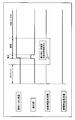
- FIG. 2 is a time chart showing an example of an operation at the time of startup of the solid oxide fuel cell (SOFC) according to Embodiment 1 of the present invention.
- FIG. 2 shows the period before and after ignition and until the reforming reaction carried out in the reforming unit 6 is switched from the partial oxidation reforming reaction to the autothermal reforming reaction.
- a period can be distinguished from a period in which the raw material is combusted by ignition and a period in which the partial oxidation reforming reaction to the autothermal reforming reaction proceed.
- the horizontal axis is the time axis, and the raw material flow rate is turned ON / OFF (whether or not raw material is supplied), the ignition unit 8 is turned ON / OFF, and the reforming air flow rate is ON / OFF (reforming air supply) ) And ON / OFF of the power generation air flow rate (whether or not the power generation air is supplied).
- ON of the raw material flow rate, the reforming air flow rate, and the power generation air flow rate indicates that the raw material, reforming air, and power generation air are being supplied
- OFF means the raw material flow rate and the reforming air flow rate.
- the state in which the supply of air and power generation air is stopped is shown.
- the section rising in the straight line extending in the horizontal axis indicating the passage of time of each of the raw material flow rate, the ignition part, the reforming air flow rate, and the power generation air flow rate is in the ON state
- the falling section Corresponds to the OFF state.
- pre-purge is performed to remove moisture and residual gas remaining inside and outside the fuel cell 3 using reforming air and power generation air.
- reforming air is supplied to the fuel cell module 1 by the reforming air supply unit 11 and power generation air is supplied to the fuel cell module 1 by the power generation air supply unit 12.
- the supplied reforming air and power generation air are sent into and out of the fuel battery cell 3 to exhaust and remove moisture, residual gas, and the like remaining inside and outside the fuel battery cell 3 to the outside.
- the reforming air supply unit 11 stops the supply of the reforming air before the pre-purge ends and before the ignition by the ignition unit 8 is performed.
- a predetermined time is set as a period for performing the pre-purge, and the main control unit 19 activates a time measuring unit (not shown) to manage the passage of the predetermined time.
- the main control unit 19 instructs the reforming air supply unit 11 to stop the supply of the reforming air.
- the reforming air supply unit 11 stops the supply of the reforming air.
- the main control unit 19 instructs the ignition unit 8 to ignite.
- the ignition unit 8 performs ignition in accordance with an instruction from the main control unit 19. While the ignition unit 8 is igniting, the main control unit 19 instructs the raw material supply unit 10 to supply the raw material to the fuel cell module 1.
- the raw material supply unit 10 starts the supply of raw materials in response to an instruction from the main control unit 19.
- the ignition part 8 stops ignition.
- the main control unit 19 resumes supplying the reforming air to the reforming air supply unit 11. Instruct them to do so.
- the reforming air supply unit 11 starts supplying reforming air in response to an instruction from the main control unit 19. Thereby, the partial oxidation reforming reaction is performed in the reforming unit 6.
- the reforming air is continuously supplied to the fuel cell module 1 even at the time of ignition after the elapse of the pre-purge period.
- the SOFC according to Embodiment 1 is configured to ignite and burn the raw material by the ignition unit in a state where the supply of the reforming air is stopped and only the raw material and power generation air are supplied. ing.
- the reforming air is not supplied to the combustion chamber 5 in a state where the raw material is mixed, and it is avoided that the ignition stability is hindered. Can do.
- power generation air enters the combustion chamber 5 from outside the flame as oxygen necessary for maintaining combustion, thereby improving flame stability and suppressing generation of carbon monoxide. .
- the peak value of the generated carbon monoxide concentration was 250 ppm.
- the peak value of the generated carbon monoxide concentration could be reduced to 50 ppm.
- the mixed raw material and reforming air are jetted from the inside of the plurality of cylindrical fuel cells 3 to the combustion chamber 5, and the power generation air is supplied to the plurality of cylindrical fuel cells 3.
- so-called premixed combustion is performed in which the fuel is sent from the outside to the combustion chamber 5, the ignition unit 8 is operated to ignite the raw material, and a flame is formed at the outlets 3 a of the plurality of fuel cells 3.
- the SOFC according to the first embodiment is not configured to attract reforming air corresponding to primary air, but is configured to forcibly supply air, and power generation air corresponding to secondary air is also diffused and sucked. This is not a configuration for performing forced air supply.
- the factors governing the ignition characteristics were examined in more detail.
- the ignition limit and the peak value of carbon monoxide generation at the time of ignition were examined based on the primary air ratio based on the reforming air flow rate and the total air ratio obtained by adding the reforming air flow rate and the power generation air flow rate. It was found that the suppression of carbon monoxide generation is affected by the primary air ratio due to the reforming air flow rate. In other words, due to the difference in configuration from Bunsen burner and the like, mixing of reforming air into the raw material hinders ignition stability, and specifically when the primary air ratio becomes extremely small (0 to 0.1). It was found that the generation peak value of carbon monoxide can be suppressed.
- the supply of reforming air is stopped at the time of ignition, so that the ignition stability is excellent, and as described above, carbon monoxide is generated at the time of ignition.
- the peak value can be suppressed to 50 ppm.
- the SOFC according to the first embodiment supplies power generation air and reforming air, performs pre-purge before starting the ignition of the raw material, and then stops only the supply of reforming air. Subsequently, the supply of the raw material is started, and the combustion is performed in the combustion chamber 5 together with the power generation air that is continuously supplied, and then the reforming air is supplied again.
- pre-purge at the time of starting, the water
- FIG. 3 is a time chart showing an example of an operation at the time of startup of the solid oxide fuel cell (SOFC) according to the first modification of the first embodiment of the present invention.
- FIG. 3 shows the period before and after ignition and the period until the autothermal reforming reaction is performed in the reforming unit 6 as in FIG. 2. The period for performing the pre-purge, the period for performing the ignition, and the raw material by the ignition. It is possible to distinguish between the period during which the fuel burns and the period during which the partial oxidation reforming reaction to the autothermal reforming reaction proceed.
- the reforming air flow rate control unit 15 when the supply of reforming air is resumed after ignition, the reforming air flow rate control unit 15 is in accordance with an instruction from the main control unit 19. Gradually changes the opening, and the reforming air supply unit 11 supplies the reforming air to the fuel cell module 1. At this time, the reforming air flow rate control unit 15 adjusts the amount so as to increase by 0.1 NL / sec, for example, within a range where the flow rate of the reforming air per unit time is not more than a predetermined flow rate.
- the SOFC according to the second embodiment has a purification unit temperature for detecting the temperature of the inlet portion of the exhaust gas purification unit 9 in the configuration of the SOFC according to the first embodiment. It is set as the structure further provided with the detection sensor (temperature detection part for purification
- FIG. Based on the detection result of the purification unit temperature detection sensor 21, the main control unit 19 supplies the water supply unit 13 and the water flow rate control unit 17 with reforming water having a predetermined flow rate to reform the fuel cell module 1. It differs from the SOFC according to the first embodiment in that it instructs the unit 6 to supply it.
- the main control unit 19 instructs the water supply unit 13 and the water flow rate control unit 17 based on the detection result of the purification unit temperature detection sensor 21 to reform the predetermined flow rate. Increase the amount of water at an appropriate time.
- the SOFC according to the second embodiment has the same configuration as the SOFC according to the first embodiment. Therefore, the same members are denoted by the same reference numerals, and the description thereof is omitted.
- FIG. 4 is a schematic diagram showing an overall configuration of a solid oxide fuel cell (SOFC) according to Embodiment 2 of the present invention.
- SOFC solid oxide fuel cell
- the amount of water for reforming is increased for the following reasons. That is, if a large amount of water for reforming is introduced at a stage where the temperature of the reforming unit 6 and the fuel cell 3 does not rise sufficiently, the operation stability and the flame temperature are lowered, and the concentration of carbon monoxide generated thereby. This is because there is a problem that becomes larger. Therefore, in the SOFC according to the second embodiment, the reforming water to be supplied based on the temperature of the exhaust gas purification unit 9 that rises with the reforming unit 6 and the fuel cell 3 while gradually supplying the reforming water. Increase the flow rate.
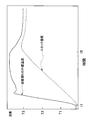
- FIG. 5 shows the relationship between the CO concentration discharged outside the system when the solid oxide fuel cell (SOFC) according to Embodiment 2 of the present invention is started up and the temperature of the inlet portion of the exhaust gas purification unit 9 (inlet temperature). It is a graph which shows. In FIG. 5, the horizontal axis of the graph represents time (t), the left vertical axis represents the CO concentration discharged outside the system (C), and the right vertical axis represents the inlet temperature (T) of the exhaust gas purification unit 9. .
- the broken line indicates the time series change of the CO concentration in the SOFC cited as a comparative example for explaining the effect of the SOFC according to the second embodiment
- the solid line indicates the time series of the CO concentration in the SOFC according to the second embodiment.
- a change and a dashed-dotted line show the time-series change of the inlet temperature of the exhaust gas purification unit 9.
- t1 is an elapsed time from the start of startup to ignition
- t2 is an elapsed time from the start of startup to the start of supply of reforming water
- t3 is a start of the SOFC according to the comparative example from the start of startup to reforming.
- t4 indicates the elapsed time from the start of startup in the SOFC according to the comparative example until the amount of reforming water is further increased. As will be described later, this t4 is also the elapsed time from the start of start-up in the SOFC according to Embodiment 2 until the amount of reforming water is first increased.
- C1 on the vertical axis indicating the CO concentration corresponds to a value at which the peak value of the CO concentration generated in the SOFC according to Embodiment 2 mainly appears
- T1 on the vertical axis indicating the inlet temperature of the exhaust gas purification unit 9 is This corresponds to a predetermined temperature (for example, 120 ° C.) at which the function of the exhaust gas purification unit 9 can be secured.
- the inlet temperature of the exhaust gas purification unit 9 is heated by the combustion exhaust gas generated in the combustion chamber 5, gradually increases in temperature, and changes so as to become substantially constant after a certain amount of time has passed.
- the time series change (solid line) of the CO concentration in the SOFC according to the second embodiment and the time series change (dashed line) of the CO concentration in the SOFC according to the comparative example are different in magnitude, but have two peaks. Appears.
- the first peak is caused by CO generated at the time of ignition.
- the second peak is caused by the reforming water supplied when the partial oxidation reforming reaction is shifted to the autothermal reforming reaction.
- the flame stability is inhibited by the reforming water supply. It shows that the CO concentration has increased.
- the first peak in the SOFC according to the comparative example is due to CO generated at the time of ignition.
- the second peak is attributed to the reforming water supplied during the transition from the partial oxidation reforming reaction to the autothermal reforming reaction, and the first increase in the reforming water. Since the flame stability was inhibited and CO was generated at each of the time and the first increase, the CO concentration was greatly increased.
- the SOFC according to the second embodiment is not affected by the increase in the CO concentration accompanying the initial increase in the reforming water.
- the reforming water In response to the increase in the CO concentration accompanying the first increase in the value of the second peak, the value of the second peak is increased. The difference between the two will be described below.
- the difference between the SOFC according to Embodiment 2 and the SOFC according to the comparative example is that the former does not increase the amount of reforming water at t3, but increases the amount of reforming water at t4, whereas the latter increases at t3. This is that the amount of water for reforming supplied to the reforming unit 6 is increased.
- the steam stability is also lowered because the steam is also ejected from the outlet 3a of the fuel cell 3 together with the reforming air and the reformed gas (fuel).
- the concentration of CO to be increased is also lowered.
- the inlet temperature of the exhaust gas purification unit 9 is the activation temperature of the purification catalyst (oxidation catalyst) provided in the exhaust gas purification unit 9 at t3. It is lower than (for example, 120 ° C.), and the exhaust gas purification unit 9 does not sufficiently secure the exhaust gas purification function. For this reason, in the SOFC according to the comparative example, the CO concentration exhausted out of the system (outside the fuel cell module) at t3 cannot be reduced, and the CO concentration is 2 as shown by the broken line in the graph of FIG. The value is high at the first peak.
- the inlet temperature of the exhaust gas purification unit 9 exceeds the activation temperature (T1) of the purification catalyst at t4, and the exhaust gas purification unit 9 Since the exhaust gas purification function is sufficiently ensured, the concentration of CO discharged outside the system can be reduced. As a result, as shown by the solid line in the graph of FIG. 5, the peak of the CO concentration due to the increase in the reforming water does not occur, and good exhaust gas characteristics are exhibited.
- the second CO concentration peak is slightly generated due to the supply of the reforming water.
- the SOFC according to Embodiment 2 is configured not to supply reforming water by advancing the partial oxidation reforming reaction until the inlet temperature of the exhaust gas purifying unit 9 reaches the activation temperature of the purifying catalyst.
- the second CO concentration peak can be avoided.
- the purification catalyst provided in the exhaust gas purification unit 9 for example, an oxidation catalyst mainly composed of noble metals can be used, and CO purification performance can be secured by this purification catalyst.
- this purification catalyst it is necessary to set the temperature to a predetermined temperature or higher.
- a heater for heating the exhaust gas purification unit 9 is separately provided and the purification catalyst is set to a predetermined temperature or higher by the heater when the SOFC is activated.
- the SOFC according to the second embodiment as described above, in consideration of the characteristics of the reforming reaction to be performed, the amount of reforming water is not increased until a predetermined temperature at which the purification catalyst is activated is reached. A unique sequence was executed, which made it possible to eliminate the need for a heater.
- the exhaust gas purification unit 9 is configured to include an oxidation catalyst mainly composed of noble metals as a purification catalyst. However, if the purification catalyst can ensure CO purification performance, The material and shape are not limited. Further, the exhaust gas purification unit 9 is configured to include a purification catalyst that is activated at a predetermined temperature. However, the exhaust gas purification unit 9 is not necessarily provided with a purification catalyst, and may be configured to effectively remove CO at a predetermined temperature or higher. Is optional.
- FIG. 6 is a schematic diagram showing an overall configuration of a solid oxide fuel cell (SOFC) according to Embodiment 3 of the present invention.
- SOFC solid oxide fuel cell
- FIGS. 1 and 4 in order to explain the invention more clearly, in the fuel cell module 1, the flow paths of the raw material, reformed gas (fuel), reforming gas, reforming water, and power generation air are described. It is not specified in particular.
- FIG. 7 is a graph showing the temperature characteristics of the reforming unit 6 and the stack 4 at the time of starting the solid oxide fuel cell (SOFC) according to the third embodiment.
- the SOFC according to the third embodiment is a table showing a correspondence relationship between the outer wall temperature of the reforming unit 6 and the stack temperature according to the operation time of the SOFC in the configuration of the SOFC according to the first embodiment.
- a storage unit 30 that holds information 31 is provided.
- the SOFC according to the third embodiment has the same configuration as the SOFC according to the first embodiment. Therefore, the same members are denoted by the same reference numerals, and the description thereof is omitted.
- the horizontal axis of the graph is time (t)
- the vertical axis is temperature (T)
- the broken line in the graph indicates the stack temperature
- the solid line indicates the outer wall temperature of the reforming unit 6 that is the object to be heated.
- t1 represents an elapsed time from the start of activation to ignition
- t5 represents an elapsed time from the start of activation to the start of power generation.
- the stack temperature is set in the vicinity of the fuel cell 3 (A in FIG. 6) located at the center in the horizontal direction and the center in the vertical direction of the stack 4 where the plurality of fuel cells 3 are arranged. ). Further, the outer wall temperature of the reforming section 6 was measured on the lower side (B in FIG. 6) of the reforming section 6 above the flame formed in the combustion chamber 5. And the table information 31 which shows the correspondence of both was created. Since the reforming water is evaporated at the inlet portion of the reforming section 6, the temperature was measured on the outer wall near the outlet portion where the reforming reaction is proceeding.
- the stack temperature and the outer wall temperature of the reforming unit 6 each increase from the time when the SOFC according to Embodiment 3 is activated and the raw material is supplied and ignited (time t1). Since the heat capacity of the stack 4 is larger than the heat capacity of the outer wall of the reforming unit 6, the stack temperature gradually rises, whereas the outer wall temperature of the reforming unit 6 forms a flame immediately below the reforming unit 6. Has been rising rapidly. Thus, the outer wall of the reforming unit 6 has high responsiveness to temperature changes in the fuel cell module 1.
- the temperature change of the outer wall temperature of the reforming unit 6 and the temperature change of the stack temperature are different in magnitude of change per unit time, but are correlated. That is, the outer wall temperature and the stack temperature of the reforming unit 6 cause the reforming unit 6 to proceed with the partial oxidation reforming reaction, the autothermal reforming reaction, the steam reforming reaction, and the reforming reaction after ignition of the raw material.
- the power generation is started and the power generation is continued at the rated output (for example, 800 W)
- the power is stabilized at a predetermined temperature (for example, 630 ° C.). That is, the temperature change of the stack temperature has a correlation with the temperature change of the outer wall temperature of the reforming unit 6.
- table information 31 indicating the correspondence relationship between the temperature characteristics shown in FIG. 7 is prepared in advance and stored in the storage unit 30.
- the main control unit 19 refers to the table information 31 so that the stack temperature can be grasped based on the outer wall temperature of the reforming unit 6 detected by the temperature detection sensor 18. It is configured.
- the fuel cell module 1 is highly reliable by detecting the temperature of the reforming unit 6 having excellent responsiveness to a temperature change and making an ignition determination on the raw material based on the detected temperature change. Combustion detection can be realized.
- the ignition determination in the SOFC according to the third embodiment will be described.
- the temperature of the reforming unit 6 is set as a detection target of the temperature detection sensor 18, and the main control unit 19 determines a predetermined value of the reforming unit 6 after supplying the raw material based on the detection result of the temperature detection sensor 18. Understand temperature changes over time. And it is comprised so that the ignition control of the raw material by the ignition part 8 may be performed based on the temperature change which the main control part 19 grasped
- the main control unit 19 determines that the outer wall temperature of the reforming unit 6 has increased by a predetermined temperature (for example, 15 ° C.) or more within a predetermined time (for example, 20 seconds) after supplying the raw material, the combustion chamber 5, it is determined that the raw material has been ignited.
- a predetermined temperature for example, 15 ° C.
- a predetermined time for example, 20 seconds
- the main control unit 19 determines that ignition has not occurred.
- the temperature of the combustion region (the combustion exhaust gas in the combustion chamber 5) can be considered as the detection target of the temperature detection sensor 18, but in this case, the responsiveness to the temperature change is the reforming unit 6. Even higher than the outer wall temperature.
- the detection accuracy may be lowered.
- the temperature detection sensor 18 is provided in the vicinity of the flame, there is a problem that flame stability is hindered and carbon monoxide is generated. Therefore, in the SOFC according to Embodiment 3, the temperature change of the temperature detection sensor 18 provided on the outer wall portion of the reforming unit 6 is used for ignition determination.
- the detection target for detecting the temperature in order to perform the ignition determination is not limited to the outer wall of the reforming unit 6, and may be another member that changes in temperature with combustion in the combustion chamber 5.
- the outer wall of the reforming unit 6 instead of the outer wall of the reforming unit 6, for example, the internal temperature or the inner wall temperature of the reforming unit 6 may be used.
- the temperature detection sensor 18 used for the ignition determination is provided to detect the temperature of the reforming unit 6 in order to switch the reforming reaction performed in the reforming unit 6 as described in the first embodiment. You can share what is being used. For this reason, there is an advantage that the number of parts can be reduced without separately providing the temperature detection sensor 18 for the ignition determination.
- the stack wall temperature is grasped by using the outer wall temperature of the reforming unit 6 that is highly responsive to temperature changes, and the raw material by the ignition unit 8 in the combustion chamber 5 is obtained. It was the structure which performs an ignition determination.
- the stack temperature falls within a predetermined temperature range, for example, the endurance limit range, using the correspondence relationship between the outer wall temperature of the reforming unit 6 and the stack temperature. Configure to manage.
- the endurance limit range indicates a range from the stack endurance upper limit temperature to the stack endurance lower limit temperature, and is a temperature range determined as a range in which the stack 4 does not deteriorate.
- the stack temperature is set when the fuel cell module 1 is in a thermally stable state as in the case where power generation is continued at the rated output. It is important to operate so as to be within the endurance limit range.
- the SOFC configuration according to the first modification of the third embodiment is the same as that of the SOFC configuration according to the third embodiment except that the contents of the table information 31 held by the storage unit 30 are different from those of the SOFC configuration according to the third embodiment. Become. For this reason, the same code
- the storage unit 30 corresponds to the power generation amount and the temperature of the reforming unit 6 corresponding to the stack durability upper limit temperature and the stack durability lower limit temperature. Information indicating the relationship is held in the storage unit 30 as table information 31.
- the storage unit 30 can use a main storage device such as a main memory, for example.
- FIG. 8 is a graph showing temperature characteristics during power generation in the solid oxide fuel cell (SOFC) according to the third embodiment.
- the horizontal axis of the graph is the power generation amount (G)
- the vertical axis is the outer wall temperature (T) of the reforming unit 6
- the solid line of the graph is the upper limit temperature of the stack 4
- the broken line of the graph is the endurance of the stack 4 It is the outer wall temperature of the reforming unit 6 corresponding to the lower limit temperature.
- the stack durability upper limit temperature and the stack durability lower limit temperature are set to predetermined values for the stack 4 respectively.
- the outer wall temperature of the reforming unit 6 corresponding to each of the stack durability upper limit temperature and the stack durability lower limit temperature is reformed from the utilization rate of fuel used for power generation, the utilization rate of power generation air, the combustion state, and the combustion chamber 5. It is governed by the heat balance in the fuel cell module 1 including heat transfer to the part 6, heat dissipation in the reforming part 6, and the like. For this reason, as shown in FIG. 8, the outer wall temperature of the reforming unit 6 corresponding to the stack durability upper limit temperature and the stack durability lower limit temperature changes according to the amount of power generation. In addition, as shown in FIG.
- the outer wall temperature of the reforming unit 6 corresponding to the stack durability upper limit temperature and the stack durability lower limit temperature tends to decrease as the amount of power generation increases. This is because the fuel utilization rate increases as the amount of power generation increases in the SOFC, the fuel ratio decreases in the combustion chamber 5, and the moisture ratio increases. For this reason, the temperature of the flame formed in the combustion chamber 5 tends to decrease, and combustion tends to become unstable.
- the outer wall temperature of the reforming unit 6 correlates with the stack temperature. Therefore, the outer wall temperature of the reforming unit 6 is controlled in accordance with the amount of power generation so that the stack temperature falls within an appropriate setting range (the range from the stack durability upper limit temperature to the stack durability lower limit temperature).
- the change in the power generation amount is the outer wall temperature of the reforming unit 6 corresponding to TDR (Turn Down Ratio) required for the combustion equipment, and the variation range of the combustion amount is the stack durability upper limit temperature and the stack durability lower limit temperature, respectively.
- TDR Transmission Down Ratio
- the stack temperature is controlled to be within the endurance limit range (the range from the stack endurance upper limit temperature to the stack endurance lower limit temperature). Can do.
- the fuel that was not used for power generation ejected from the outlet 3a in the upper part of the fuel cell 3 and the power generation air that was not used for power generation diffusely burned.
- both the stack temperature and the temperature of the reforming unit 6 are decreased in proportion to the increase in the air ratio.
- both the stack temperature and the temperature of the reforming unit 6 increase in proportion to the drop in the air ratio.
- the temperature of the reforming unit 6 and the stack temperature corresponding to the temperature of the reforming unit 6 can be adjusted by adjusting the supplied air ratio during diffusion combustion during power generation. More specifically, the outer wall temperature of the reforming unit 6 is controlled as follows.
- the air supply unit 12 and the power generation air flow rate control unit 16 are instructed to increase the flow rate of power generation air.
- the power generation air flow rate control unit 16 increases the opening so that the flow rate of the power generation air to be supplied increases, and the power generation air supply unit 12 controls the power generation air flow rate control.
- the reforming air having a flow rate instructed from the main control unit 19 is supplied to the fuel cell module 1 via the unit 16.
- the main control unit 19 controls the raw material supply unit 10 and the raw material flow rate control.
- the unit 14 is further instructed to reduce the flow rate of the raw material supplied.
- the raw material flow rate control unit 14 decreases the opening so that the flow rate of the supplied raw material decreases, and the raw material supply unit 10 performs main control via the raw material flow rate control unit 14.
- a raw material having a flow rate instructed by the unit 19 is supplied to the fuel cell module 1.
- the main control unit 19 determines that the outer wall temperature of the reforming unit 6 is lower than the temperature corresponding to the stack durability lower limit temperature based on the detection result received from the temperature detection sensor 18, first, the power generation air supply unit 12 The power generation air flow rate control unit 16 is instructed to reduce the flow rate of the power generation air. Further, when it is determined that the detection result received from the temperature detection sensor 18 does not fall within the set temperature range even if the flow rate of the power generation air is decreased, the main control unit 19 controls the raw material supply unit 10 and the raw material flow rate control unit 14. To increase the flow rate of the raw material supplied.
- the main control unit 19 can control the outer wall temperature of the reforming unit 6 so as to fall within a range from a temperature corresponding to the stack durability upper limit temperature to a temperature corresponding to the stack durability lower limit temperature. .
- the main control unit 19 blows off the flame ( Blow Off), misfire due to quenching, etc. If it is determined that the combustion is abnormal, the main control unit 19 instructs the raw material supply unit 10 and the raw material flow rate control unit 14 to stop the supply of the raw material and stop the combustion.
- the determination as to whether or not the above-described abnormal combustion has occurred is specifically performed as follows.
- the outer wall temperature of the reforming unit 6 is set within the set temperature range corresponding to the endurance limit range corresponding to the power generation amount. For example, when the flow rate is changed by ⁇ 10% and the outer wall temperature of the reforming unit 6 does not return within the set temperature range, the main control unit 19 determines that the combustion is abnormal.
- the main control unit 19 determines that the combustion is abnormal.
- the stack temperature is controlled to be within the endurance limit range by adjusting the outer wall temperature of the reforming unit 6 to be within the set temperature range. It is not limited. For example, only the determination as to whether or not the stack temperature is outside the endurance limit range is made based on the outer wall temperature of the reforming unit 6.
- the configuration is such that the temperature of the stack 4 is directly controlled to be within the endurance limit range by changing the flow rate of the power generation air or the raw material as described above. There may be. In the case of such a configuration, a temperature detection sensor is also provided in the stack 4 separately.
- the carbon monoxide concentration of the combustion exhaust gas is set to a predetermined value (for example, 150 ppm) or less so that the reforming unit 6 It was found that the outer wall temperature can be controlled.
- the SOFC according to Modification 2 of Embodiment 3 is modified so that the CO concentration in the combustion exhaust gas becomes a predetermined value or less from the correspondence relationship between the outer wall temperature of the reforming unit 6 and the CO concentration in the combustion exhaust gas.
- the outer wall temperature of the mass part 6 is controlled. In this way, from the correspondence between the outer wall temperature of the reforming unit 6 and the CO concentration, the outer wall temperature of the reforming unit 6 is controlled so that the CO concentration becomes a predetermined value or less, so that the CO concentration is taken into consideration. It becomes possible to control the outer wall temperature of the reforming section 6.
- the SOFC according to the second modification of the third embodiment has the same configuration as the SOFC according to the third embodiment except that the table information 31 held in the storage unit 30 is different. For this reason, the same code
- the storage unit 30 holds information indicating the correspondence between the outer wall temperature of the reforming unit 6 and the CO concentration corresponding to the change in the air ratio as the table information 31.
- the main control unit 19 performs combustion based on the detection result received from the temperature detection sensor 18 according to the air ratio of the power generation air supplied to the combustion chamber 5.
- the CO concentration in the exhaust gas can be grasped.
- the air ratio described above is such that the main control unit 19 manages the air flow rate supplied to the fuel cell module 1 by the power generation air supply unit 12 via the power generation air flow rate control unit 16, and the power generation amount in the SOFC And the air flow rate to be supplied.
- the SOFC according to the third modification of the third embodiment has a configuration in which the first modification and the second modification of the third embodiment are combined, the outer wall temperature of the reforming unit 6 according to the amount of power generation, and the stack From the correspondence relationship between the temperature and the CO concentration in the combustion exhaust gas, the outer wall of the reforming unit 6 is set so that the stack temperature is within the endurance limit range according to the amount of power generation and the CO concentration in the combustion exhaust gas is equal to or less than a predetermined value. Configure to control temperature.
- the SOFC according to the third modification of the third embodiment is the same as the SOFC according to the third embodiment shown in FIG. 6 except that the table information 31 held in the storage unit 30 is different. For this reason, the same code
- the table information 31 corresponds to the outer wall temperature of the reforming unit 6 corresponding to the stack durability upper limit temperature and the stack durability lower limit temperature corresponding to the power generation amount, and the fluctuation of the air ratio. Information indicating the correspondence between the outer wall temperature of the reforming unit 6 and the CO concentration in the combustion exhaust gas is held.
- the main control unit 19 refers to the table information 31 from the set power generation amount and the detection result received from the temperature detection sensor 18, and keeps the stack temperature within the endurance limit range while maintaining the CO concentration in the combustion exhaust gas.
- the outer wall temperature of the reforming unit 6 can be controlled so as to be suppressed to a predetermined value or less.
- the main control unit 19 preferentially adjusts the outer wall temperature of the reforming unit 6 so that the stack temperature is within the endurance limit range. Control.
- the flame stability in the fuel cell module 1 is not good and the combustion range is narrow
- the CO concentration in the combustion exhaust gas reaches a predetermined value (for example, 150 ppm)
- the outer wall temperature of the reforming unit 6 is adjusted.
- Preferential control is performed so that the CO concentration becomes a predetermined value or less.
- the ignition determination described in the third embodiment and the first modification of the third embodiment It is desirable that the range (combustion detection range) in which the presence or absence of abnormal combustion described above can be determined is wide.
- the temperature detection sensor is configured so that the outer wall temperature of the reforming unit 6 is below the reforming unit 6 and in the vicinity of the outlet of the reforming unit 6.
- 18 is configured to measure the temperature, but is not limited to the vicinity of the outlet, and if the combustion status and the progress of the reforming reaction can be grasped, the internal temperature of the reforming unit 6,
- a temperature detection sensor 18 may be provided so as to detect the inner wall temperature. Further, in the case where the temperature detection sensor 18 is provided on the outer wall of the reforming unit 6, it is preferable to detect the temperature of the contact portion with the outer wall by the temperature detection sensor 18, but the present invention is not limited to this.
- the SOFC according to the present invention ignites a raw material at the time of start-up, heats a reforming part or the like with heat of generated combustion exhaust gas, and implements a reforming reaction, a domestic fuel cell system, a commercial fuel cell system, or various types It can be widely used for applications such as power supply systems.
Landscapes
- Chemical & Material Sciences (AREA)
- Engineering & Computer Science (AREA)
- Chemical Kinetics & Catalysis (AREA)
- Sustainable Energy (AREA)
- Manufacturing & Machinery (AREA)
- Sustainable Development (AREA)
- Life Sciences & Earth Sciences (AREA)
- Electrochemistry (AREA)
- General Chemical & Material Sciences (AREA)
- Combustion & Propulsion (AREA)
- Organic Chemistry (AREA)
- Health & Medical Sciences (AREA)
- General Health & Medical Sciences (AREA)
- Inorganic Chemistry (AREA)
- Fuel Cell (AREA)
Abstract
Priority Applications (5)
| Application Number | Priority Date | Filing Date | Title |
|---|---|---|---|
| JP2016514686A JP6023917B2 (ja) | 2014-04-25 | 2015-02-09 | 固体酸化物形燃料電池 |
| EP15782495.4A EP3136485B1 (fr) | 2014-04-25 | 2015-02-09 | Pile à combustible à oxyde solide |
| EP18186454.7A EP3429008B1 (fr) | 2014-04-25 | 2015-02-09 | Pile à combustible à oxyde solide |
| US15/037,918 US10096849B2 (en) | 2014-04-25 | 2015-02-09 | Solid oxide fuel cell system |
| US16/118,058 US10629926B2 (en) | 2014-04-25 | 2018-08-30 | Solid oxide fuel cell system |
Applications Claiming Priority (2)
| Application Number | Priority Date | Filing Date | Title |
|---|---|---|---|
| JP2014090930 | 2014-04-25 | ||
| JP2014-090930 | 2014-04-25 |
Related Child Applications (2)
| Application Number | Title | Priority Date | Filing Date |
|---|---|---|---|
| US15/037,918 A-371-Of-International US10096849B2 (en) | 2014-04-25 | 2015-02-09 | Solid oxide fuel cell system |
| US16/118,058 Division US10629926B2 (en) | 2014-04-25 | 2018-08-30 | Solid oxide fuel cell system |
Publications (1)
| Publication Number | Publication Date |
|---|---|
| WO2015162833A1 true WO2015162833A1 (fr) | 2015-10-29 |
Family
ID=54332016
Family Applications (1)
| Application Number | Title | Priority Date | Filing Date |
|---|---|---|---|
| PCT/JP2015/000572 Ceased WO2015162833A1 (fr) | 2014-04-25 | 2015-02-09 | Pile à combustible à oxyde solide |
Country Status (4)
| Country | Link |
|---|---|
| US (2) | US10096849B2 (fr) |
| EP (2) | EP3429008B1 (fr) |
| JP (1) | JP6023917B2 (fr) |
| WO (1) | WO2015162833A1 (fr) |
Cited By (3)
| Publication number | Priority date | Publication date | Assignee | Title |
|---|---|---|---|---|
| JP2017201620A (ja) * | 2016-04-28 | 2017-11-09 | パナソニックIpマネジメント株式会社 | 高温動作型燃料電池システムおよび高温動作型燃料電池システムの運転方法 |
| US20180309145A1 (en) * | 2017-04-21 | 2018-10-25 | Panasonic Intellectual Property Management Co., Ltd. | High-temperature operation fuel cell system |
| JP2019220365A (ja) * | 2018-06-21 | 2019-12-26 | 本田技研工業株式会社 | 燃料電池モジュール及びその運転方法 |
Families Citing this family (2)
| Publication number | Priority date | Publication date | Assignee | Title |
|---|---|---|---|---|
| US10865985B2 (en) * | 2018-02-20 | 2020-12-15 | General Electric Technology Gmbh | System and method for operating a combustion chamber |
| KR102727968B1 (ko) * | 2019-05-29 | 2024-11-07 | 현대자동차주식회사 | 연료전지용 개질기의 운전 제어 시스템 |
Citations (7)
| Publication number | Priority date | Publication date | Assignee | Title |
|---|---|---|---|---|
| JP2006073215A (ja) * | 2004-08-31 | 2006-03-16 | Matsushita Electric Ind Co Ltd | 燃料電池システム |
| JP2008135268A (ja) * | 2006-11-28 | 2008-06-12 | Kyocera Corp | 燃料電池装置の起動方法 |
| JP2009295534A (ja) * | 2008-06-09 | 2009-12-17 | Yamatake Corp | 燃料電池システムおよび燃料電池システムの運転方法 |
| JP2010277844A (ja) * | 2009-05-28 | 2010-12-09 | Toto Ltd | 固体電解質型燃料電池 |
| JP2012079420A (ja) * | 2010-09-30 | 2012-04-19 | Toto Ltd | 固体酸化物形燃料電池装置 |
| JP2013211165A (ja) * | 2012-03-30 | 2013-10-10 | Dainichi Co Ltd | 燃料電池システム |
| JP2014022234A (ja) * | 2012-07-19 | 2014-02-03 | Toto Ltd | 固体酸化物型燃料電池 |
Family Cites Families (10)
| Publication number | Priority date | Publication date | Assignee | Title |
|---|---|---|---|---|
| JP2006233011A (ja) | 2005-02-24 | 2006-09-07 | Aisin Seiki Co Ltd | 燃料ガス処理装置 |
| US20080112859A1 (en) | 2005-02-16 | 2008-05-15 | Shigenori Onuma | Fuel Gas Processing Apparatus |
| JP4703409B2 (ja) * | 2006-01-16 | 2011-06-15 | 株式会社荏原製作所 | 燃焼装置、改質器、燃料電池発電システム、及び改質器の運転方法 |
| EP2412666A4 (fr) * | 2009-03-25 | 2014-01-08 | Panasonic Corp | Dispositif de production d'hydrogène, système pour pile à combustible pourvu de celui-ci, procédé de mise en uvre du dispositif de production d'hydrogène, et procédé de mise en uvre du système pour pile à combustible |
| US8906564B2 (en) | 2009-03-30 | 2014-12-09 | Panasonic Corporation | Hydrogen generator, fuel cell system, and method for operating hydrogen generator |
| CN103119769B (zh) | 2010-09-30 | 2015-07-29 | Toto株式会社 | 固体氧化物型燃料电池装置 |
| JP5675490B2 (ja) | 2011-05-13 | 2015-02-25 | 本田技研工業株式会社 | 燃料電池モジュール |
| JP5748055B2 (ja) | 2011-06-30 | 2015-07-15 | Toto株式会社 | 固体酸化物型燃料電池 |
| CN103579648B (zh) | 2012-07-19 | 2017-06-23 | Toto株式会社 | 固体氧化物型燃料电池 |
| JP6015907B2 (ja) | 2012-07-19 | 2016-10-26 | Toto株式会社 | 固体酸化物型燃料電池 |
-
2015
- 2015-02-09 EP EP18186454.7A patent/EP3429008B1/fr active Active
- 2015-02-09 WO PCT/JP2015/000572 patent/WO2015162833A1/fr not_active Ceased
- 2015-02-09 US US15/037,918 patent/US10096849B2/en active Active
- 2015-02-09 EP EP15782495.4A patent/EP3136485B1/fr active Active
- 2015-02-09 JP JP2016514686A patent/JP6023917B2/ja active Active
-
2018
- 2018-08-30 US US16/118,058 patent/US10629926B2/en active Active
Patent Citations (7)
| Publication number | Priority date | Publication date | Assignee | Title |
|---|---|---|---|---|
| JP2006073215A (ja) * | 2004-08-31 | 2006-03-16 | Matsushita Electric Ind Co Ltd | 燃料電池システム |
| JP2008135268A (ja) * | 2006-11-28 | 2008-06-12 | Kyocera Corp | 燃料電池装置の起動方法 |
| JP2009295534A (ja) * | 2008-06-09 | 2009-12-17 | Yamatake Corp | 燃料電池システムおよび燃料電池システムの運転方法 |
| JP2010277844A (ja) * | 2009-05-28 | 2010-12-09 | Toto Ltd | 固体電解質型燃料電池 |
| JP2012079420A (ja) * | 2010-09-30 | 2012-04-19 | Toto Ltd | 固体酸化物形燃料電池装置 |
| JP2013211165A (ja) * | 2012-03-30 | 2013-10-10 | Dainichi Co Ltd | 燃料電池システム |
| JP2014022234A (ja) * | 2012-07-19 | 2014-02-03 | Toto Ltd | 固体酸化物型燃料電池 |
Non-Patent Citations (1)
| Title |
|---|
| See also references of EP3136485A4 * |
Cited By (5)
| Publication number | Priority date | Publication date | Assignee | Title |
|---|---|---|---|---|
| JP2017201620A (ja) * | 2016-04-28 | 2017-11-09 | パナソニックIpマネジメント株式会社 | 高温動作型燃料電池システムおよび高温動作型燃料電池システムの運転方法 |
| US20180309145A1 (en) * | 2017-04-21 | 2018-10-25 | Panasonic Intellectual Property Management Co., Ltd. | High-temperature operation fuel cell system |
| JP2018186079A (ja) * | 2017-04-21 | 2018-11-22 | パナソニックIpマネジメント株式会社 | 高温動作型燃料電池システム |
| US10700368B2 (en) * | 2017-04-21 | 2020-06-30 | Panasonic Intellectual Property Management Co., Ltd. | High-temperature operation fuel cell system |
| JP2019220365A (ja) * | 2018-06-21 | 2019-12-26 | 本田技研工業株式会社 | 燃料電池モジュール及びその運転方法 |
Also Published As
| Publication number | Publication date |
|---|---|
| US10096849B2 (en) | 2018-10-09 |
| US20160293981A1 (en) | 2016-10-06 |
| US10629926B2 (en) | 2020-04-21 |
| EP3136485A1 (fr) | 2017-03-01 |
| US20180375126A1 (en) | 2018-12-27 |
| EP3429008A1 (fr) | 2019-01-16 |
| JPWO2015162833A1 (ja) | 2017-04-13 |
| EP3136485B1 (fr) | 2018-10-31 |
| JP6023917B2 (ja) | 2016-11-09 |
| EP3136485A4 (fr) | 2017-05-17 |
| EP3429008B1 (fr) | 2022-11-02 |
Similar Documents
| Publication | Publication Date | Title |
|---|---|---|
| JP6023917B2 (ja) | 固体酸化物形燃料電池 | |
| JP6138378B2 (ja) | 燃料電池システム | |
| CN101421181B (zh) | 氢生成装置、具备该装置的燃料电池系统以及其运行方法 | |
| JP5847617B2 (ja) | 燃料電池システム | |
| JP7162170B2 (ja) | 固体酸化物形燃料電池システム | |
| JP2008273763A (ja) | 改質装置および燃料電池システム | |
| JP5213345B2 (ja) | 燃料電池装置 | |
| JP6960610B2 (ja) | 燃料電池システムおよび燃料電池システムの運転方法 | |
| JP2015144092A (ja) | 燃料電池装置 | |
| JP6638464B2 (ja) | 燃料電池システム | |
| JP6776769B2 (ja) | 燃料電池装置 | |
| JP6701804B2 (ja) | 燃料電池システム | |
| JP5309799B2 (ja) | 改質装置および燃料電池システム | |
| WO2012132409A1 (fr) | Dispositif de production d'hydrogène et son procédé de fonctionnement | |
| JP6424492B2 (ja) | 燃料電池システム | |
| JP2007273281A (ja) | 燃料電池発電装置 | |
| US10700368B2 (en) | High-temperature operation fuel cell system | |
| JP6458252B2 (ja) | 水素生成装置と、それを備えた燃料電池システム、および、それらの運転方法 | |
| JP6444197B2 (ja) | 燃料電池モジュール | |
| JP2010218790A (ja) | 燃料電池発電システム | |
| JP2010257823A (ja) | 燃料電池システムの燃焼装置 | |
| JP5402197B2 (ja) | 改質装置および燃料電池システム | |
| JP7003655B2 (ja) | 燃料電池システム | |
| JP6678299B2 (ja) | 水素生成装置 | |
| JP2008105861A (ja) | 改質装置 |
Legal Events
| Date | Code | Title | Description |
|---|---|---|---|
| 121 | Ep: the epo has been informed by wipo that ep was designated in this application |
Ref document number: 15782495 Country of ref document: EP Kind code of ref document: A1 |
|
| ENP | Entry into the national phase |
Ref document number: 2016514686 Country of ref document: JP Kind code of ref document: A |
|
| REEP | Request for entry into the european phase |
Ref document number: 2015782495 Country of ref document: EP |
|
| WWE | Wipo information: entry into national phase |
Ref document number: 15037918 Country of ref document: US Ref document number: 2015782495 Country of ref document: EP |
|
| NENP | Non-entry into the national phase |
Ref country code: DE |