WO2015162979A1 - 周波数領域パラメータ列生成方法、符号化方法、復号方法、周波数領域パラメータ列生成装置、符号化装置、復号装置、プログラム及び記録媒体 - Google Patents
周波数領域パラメータ列生成方法、符号化方法、復号方法、周波数領域パラメータ列生成装置、符号化装置、復号装置、プログラム及び記録媒体 Download PDFInfo
- Publication number
- WO2015162979A1 WO2015162979A1 PCT/JP2015/054135 JP2015054135W WO2015162979A1 WO 2015162979 A1 WO2015162979 A1 WO 2015162979A1 JP 2015054135 W JP2015054135 W JP 2015054135W WO 2015162979 A1 WO2015162979 A1 WO 2015162979A1
- Authority
- WO
- WIPO (PCT)
- Prior art keywords
- lsp
- frequency domain
- parameter
- sequence
- corrected
- Prior art date
- Legal status (The legal status is an assumption and is not a legal conclusion. Google has not performed a legal analysis and makes no representation as to the accuracy of the status listed.)
- Ceased
Links
Images



Classifications
-
- G—PHYSICS
- G10—MUSICAL INSTRUMENTS; ACOUSTICS
- G10L—SPEECH ANALYSIS TECHNIQUES OR SPEECH SYNTHESIS; SPEECH RECOGNITION; SPEECH OR VOICE PROCESSING TECHNIQUES; SPEECH OR AUDIO CODING OR DECODING
- G10L19/00—Speech or audio signals analysis-synthesis techniques for redundancy reduction, e.g. in vocoders; Coding or decoding of speech or audio signals, using source filter models or psychoacoustic analysis
- G10L19/04—Speech or audio signals analysis-synthesis techniques for redundancy reduction, e.g. in vocoders; Coding or decoding of speech or audio signals, using source filter models or psychoacoustic analysis using predictive techniques
- G10L19/06—Determination or coding of the spectral characteristics, e.g. of the short-term prediction coefficients
- G10L19/07—Line spectrum pair [LSP] vocoders
-
- G—PHYSICS
- G10—MUSICAL INSTRUMENTS; ACOUSTICS
- G10L—SPEECH ANALYSIS TECHNIQUES OR SPEECH SYNTHESIS; SPEECH RECOGNITION; SPEECH OR VOICE PROCESSING TECHNIQUES; SPEECH OR AUDIO CODING OR DECODING
- G10L19/00—Speech or audio signals analysis-synthesis techniques for redundancy reduction, e.g. in vocoders; Coding or decoding of speech or audio signals, using source filter models or psychoacoustic analysis
-
- G—PHYSICS
- G10—MUSICAL INSTRUMENTS; ACOUSTICS
- G10L—SPEECH ANALYSIS TECHNIQUES OR SPEECH SYNTHESIS; SPEECH RECOGNITION; SPEECH OR VOICE PROCESSING TECHNIQUES; SPEECH OR AUDIO CODING OR DECODING
- G10L19/00—Speech or audio signals analysis-synthesis techniques for redundancy reduction, e.g. in vocoders; Coding or decoding of speech or audio signals, using source filter models or psychoacoustic analysis
- G10L19/02—Speech or audio signals analysis-synthesis techniques for redundancy reduction, e.g. in vocoders; Coding or decoding of speech or audio signals, using source filter models or psychoacoustic analysis using spectral analysis, e.g. transform vocoders or subband vocoders
-
- G—PHYSICS
- G10—MUSICAL INSTRUMENTS; ACOUSTICS
- G10L—SPEECH ANALYSIS TECHNIQUES OR SPEECH SYNTHESIS; SPEECH RECOGNITION; SPEECH OR VOICE PROCESSING TECHNIQUES; SPEECH OR AUDIO CODING OR DECODING
- G10L19/00—Speech or audio signals analysis-synthesis techniques for redundancy reduction, e.g. in vocoders; Coding or decoding of speech or audio signals, using source filter models or psychoacoustic analysis
- G10L19/04—Speech or audio signals analysis-synthesis techniques for redundancy reduction, e.g. in vocoders; Coding or decoding of speech or audio signals, using source filter models or psychoacoustic analysis using predictive techniques
- G10L19/08—Determination or coding of the excitation function; Determination or coding of the long-term prediction parameters
- G10L19/12—Determination or coding of the excitation function; Determination or coding of the long-term prediction parameters the excitation function being a code excitation, e.g. in code excited linear prediction [CELP] vocoders
-
- G—PHYSICS
- G10—MUSICAL INSTRUMENTS; ACOUSTICS
- G10L—SPEECH ANALYSIS TECHNIQUES OR SPEECH SYNTHESIS; SPEECH RECOGNITION; SPEECH OR VOICE PROCESSING TECHNIQUES; SPEECH OR AUDIO CODING OR DECODING
- G10L25/00—Speech or voice analysis techniques not restricted to a single one of groups G10L15/00 - G10L21/00
- G10L25/03—Speech or voice analysis techniques not restricted to a single one of groups G10L15/00 - G10L21/00 characterised by the type of extracted parameters
- G10L25/06—Speech or voice analysis techniques not restricted to a single one of groups G10L15/00 - G10L21/00 characterised by the type of extracted parameters the extracted parameters being correlation coefficients
-
- G—PHYSICS
- G10—MUSICAL INSTRUMENTS; ACOUSTICS
- G10L—SPEECH ANALYSIS TECHNIQUES OR SPEECH SYNTHESIS; SPEECH RECOGNITION; SPEECH OR VOICE PROCESSING TECHNIQUES; SPEECH OR AUDIO CODING OR DECODING
- G10L25/00—Speech or voice analysis techniques not restricted to a single one of groups G10L15/00 - G10L21/00
- G10L25/03—Speech or voice analysis techniques not restricted to a single one of groups G10L15/00 - G10L21/00 characterised by the type of extracted parameters
- G10L25/12—Speech or voice analysis techniques not restricted to a single one of groups G10L15/00 - G10L21/00 characterised by the type of extracted parameters the extracted parameters being prediction coefficients
Definitions
- the present invention relates to coding technology, and more particularly to technology for converting frequency domain parameters equivalent to linear prediction coefficients.
- the input acoustic signal for each frame is encoded by the encoding method in the frequency domain or the encoding method in the time domain. Whether to use the encoding method in the frequency domain or the encoding method in the time domain is determined according to the characteristics of the input acoustic signal of each frame.
- linear prediction coefficients obtained by performing linear prediction analysis on the input acoustic signal are converted into a sequence of LSP parameters, and the sequence of LSP parameters is encoded to perform LSP A code is obtained and a quantized LSP parameter string corresponding to the LSP code is obtained.
- linear prediction coefficients obtained from the quantized LSP parameter sequence of the current frame and the quantized LSP parameter sequence of the previous frame are used as filter coefficients of a synthesis filter that is a time domain filter
- a synthesis filter is applied to a signal obtained by synthesizing the waveform contained in the adaptive codebook and the waveform contained in the fixed codebook to obtain a synthesized signal, and distortions between the obtained synthesized signal and the input acoustic signal are minimized. It encodes by determining the codebook index.
- the quantized LSP parameter sequence is converted into linear prediction coefficients to obtain a quantized linear prediction coefficient sequence, and the obtained quantized linear prediction coefficient sequence is smoothed to be corrected and quantized.
- a frequency domain signal sequence obtained by converting an input acoustic signal into a frequency domain using respective values of a power spectrum envelope sequence which is a frequency domain sequence corresponding to a corrected linear prediction coefficient sequence. Each value is normalized to obtain a signal from which the influence of the spectral envelope has been removed, and the obtained signal is variable-length encoded in consideration of spectral envelope information.
- linear prediction coefficients obtained by performing linear prediction analysis on the input acoustic signal are commonly used.
- the linear prediction coefficients are converted into a series of frequency domain parameters equivalent to linear prediction coefficients such as LSP (Line Spectrum Pair) parameters and ISP (Immittance Spectrum Pairs) parameters.
- LSP Line Spectrum Pair
- ISP Immittance Spectrum Pairs
- the LSP code (or ISP code) obtained by encoding the LSP parameter string (or ISP parameter string) is sent to the decoding device.
- the frequency from 0 to ⁇ of the LSP parameter used in quantization and interpolation may be described in particular in distinction from LSP frequency (LSP Frequency: LSF) or ISP frequency (ISP Frequency: ISF). In the description, such frequency parameters will be described as LSP parameters and ISP parameters.
- an LSP parameter string consisting of p LSP parameters is denoted as ⁇ [1], ⁇ [2],..., ⁇ [p].
- p is an integer prediction order of 1 or more. Symbols in square brackets ([]) represent indexes.
- ⁇ [i] is the ith LSP parameter in the LSP parameter string ⁇ [1], ⁇ [2],..., ⁇ [p].
- Symbols in square brackets on the right shoulder of ⁇ indicate frame numbers.
- the LSP parameter string generated for the acoustic signal of the f-th frame is expressed as ⁇ [f] [1], ⁇ [f] [2], ..., ⁇ [f] [p].
- parameters corresponding to the current frame (f-th frame) will be described with the frame number on the right shoulder omitted.
- the description of the frame number is omitted, it refers to the parameter generated for the current frame.
- ⁇ [i] ⁇ [f] [i] It is.
- ⁇ k [i] represents the k-th power of ⁇ [i].
- step S100 the conventional audio coding apparatus 9 receives an audio sound digital signal (hereinafter referred to as an input sound signal) in the time domain of a frame unit which is a predetermined time interval.
- the encoding device 9 performs the processing of each processing unit described below for each frame on the input acoustic signal.
- the input sound signal in frame units is input to the linear prediction analysis unit 105, the feature extraction unit 120, the frequency domain coding unit 150, and the time domain coding unit 170.
- step S105 the linear prediction analysis unit 105 performs linear prediction analysis on the input acoustic signal in units of frames to obtain and output linear prediction coefficient sequences a [1], a [2],..., A [p].
- a [i] is the i-th order linear prediction coefficient.
- the linear prediction coefficient sequence a [1], a [2],..., A [p] output from the linear prediction analysis unit 105 is input to the LSP generation unit 110.
- step S110 the LSP generation unit 110 generates a sequence ⁇ [1] of LSP parameters corresponding to the linear prediction coefficient sequence a [1], a [2], ..., a [p] output from the linear prediction analysis unit 105. , ⁇ [2],..., ⁇ [p] are obtained and output.
- a sequence ⁇ [1], ⁇ [2],..., ⁇ [p] of LSP parameters is called an LSP parameter sequence.
- LSP parameter strings ⁇ [1], ⁇ [2],..., ⁇ [p] are the sum polynomial defined by equation (2) and the parameters defined as the root of a difference polynomial defined by equation (3) It is a series.
- the LSP parameter strings ⁇ [1], ⁇ [2],..., ⁇ [p] are sequences arranged in ascending order of values. In other words, 0 ⁇ [1] ⁇ [2] ⁇ ... ⁇ [p] ⁇ Meet.
- the LSP parameter sequences ⁇ [1], ⁇ [2],..., ⁇ [p] output from the LSP generator 110 are input to the LSP encoder 115.
- step S115 the LSP coding unit 115 codes the LSP parameter string ⁇ [1], ⁇ [2],..., ⁇ [p] output from the LSP generation unit 110, and the LSP code C1 and the LSP code thereof.
- a series ⁇ ⁇ [1], ⁇ ⁇ [2], ..., ⁇ ⁇ [p] of quantized LSP parameters corresponding to C1 is obtained and output.
- a sequence ⁇ ⁇ [1], ⁇ ⁇ [2], ..., ⁇ ⁇ [p] of quantized LSP parameters is referred to as a quantized LSP parameter sequence.
- the quantized LSP parameter string ⁇ ⁇ [1], ⁇ ⁇ [2], ..., ⁇ ⁇ [p] output from the LSP encoding unit 115 is a quantized linear prediction coefficient generation unit 900, and a delay input unit 165. And the time domain coding unit 170. Further, LSP code C1 output from LSP encoding section 115 is input to output section 175.
- step S120 the feature quantity extraction unit 120 extracts the magnitude of the time variation of the input sound signal as a feature quantity.
- the feature quantity extraction unit 120 performs the subsequent process such that the quantized linear prediction coefficient generation unit 900 executes the subsequent process.
- information indicating the frequency domain coding method is input to the output unit 175 as the identification code Cg.
- the feature amount extraction unit 120 causes the time domain encoding unit 170 to execute the subsequent process.
- information indicating the time domain coding method is input to the output unit 175 as the identification code Cg.
- Each process of the quantized linear prediction coefficient generation unit 900, the quantized linear prediction coefficient correction unit 905, the approximate smoothed power spectrum envelope sequence calculation unit 910, and the frequency domain encoding unit 150 is extracted by the feature amount extraction unit 120.
- the feature amount is smaller than the predetermined threshold (ie, when the time variation of the input acoustic signal is small) (step S121).
- step S900 the quantized linear prediction coefficient generation unit 900 generates the quantized LSP parameter sequence ⁇ ⁇ [1], ⁇ ⁇ [2], ..., ⁇ ⁇ [p] output from the LSP encoding unit 115.
- a series of linear prediction coefficients ⁇ a [1], ⁇ a [2], ..., ⁇ a [p] is obtained and output.
- a series of linear prediction coefficients ⁇ a [1], ⁇ a [2], ..., ⁇ a [p] is called a quantized linear prediction coefficient sequence.
- the quantized linear prediction coefficient sequence ⁇ a [1], ⁇ a [2], ..., ⁇ a [p] output from the quantized linear prediction coefficient generation unit 900 is sent to the quantized linear prediction coefficient correction unit 905. It is input.
- step S905 the quantized linear prediction coefficient correction unit 905 outputs the quantized linear prediction coefficient sequence ⁇ a [1], ⁇ a [2], ..., ⁇ output from the quantized linear prediction coefficient generation unit 900.
- the correction coefficient ⁇ R is a predetermined positive integer equal to or less than one.
- step S 910 the approximately smoothed power spectrum envelope sequence calculation unit 910 corrects the corrected quantized linear prediction coefficient sequence ⁇ a [1] ⁇ ( ⁇ R), ⁇ output from the quantized linear prediction coefficient correction unit 905.
- Approximated smoothed power by equation (4) using each coefficient ⁇ a [i] x ( ⁇ R) i of a [2] x ( ⁇ R) 2 , ..., ⁇ a [p] x ( ⁇ R) p
- a spectral envelope sequence ⁇ W ⁇ R [1], ⁇ W ⁇ R [2], ... ⁇ W ⁇ R [N] is generated and output.
- exp ( ⁇ ) is an exponential function based on the Napier number
- j is an imaginary unit
- ⁇ 2 is predicted residual energy.
- the approximate smoothed power spectral envelope sequence ⁇ W ⁇ R [1], ⁇ W ⁇ R [2], ... ⁇ W ⁇ R [N] is the corrected quantized linear prediction coefficient It is a series of frequency domains corresponding to the columns ⁇ a [1] ⁇ (RR), aa [2] ⁇ ( ⁇ R) 2 , ... ⁇ a [p]] ( ⁇ R) p .
- the approximate smoothed power spectrum envelope sequence ⁇ W ⁇ R [1], ⁇ W ⁇ R [2],..., ⁇ W ⁇ R [N] output from the approximate smoothed power spectrum envelope sequence calculation unit 910 is frequency domain encoded. It is input to the part 150.
- Equation (4) The reason why the series of values defined by Equation (4) is called an approximate smoothed power spectrum envelope series will be described below.
- the input acoustic signal x [t] at time t has its own value x [t-1],.
- the prediction residual e [t] and the linear prediction coefficients a [1], a [2],..., A [p] are represented by equation (5).
- each coefficient W [n] (n 1,..., N) of the power spectrum envelope series W [1], W [2],. Be done.
- a [i] in equation (6) is replaced by a [i] ⁇ ( ⁇ R) i
- the series ⁇ W ⁇ R [1], ⁇ W ⁇ R [2], ... ⁇ W ⁇ R [N] defined by the equation (4) is a smoothed power spectrum envelope series W ⁇ R [defined by the equation (7) 1], W ⁇ R [2],..., W ⁇ R [N] correspond to a series of approximate values of the respective values. Therefore, the series ⁇ W ⁇ R [1], ⁇ W ⁇ R [2], ... ⁇ W ⁇ R [N] defined by the equation (4) is called an approximately smoothed power spectrum envelope series.
- frequency domain coding section 150 performs variable length coding on normalized frequency domain signal sequence X N [1], X N [2],..., X N [N] to generate a frequency domain signal code. .
- the frequency domain signal code output from frequency domain encoding section 150 is input to output section 175.
- the delay input unit 165 and the time domain encoding unit 170 are executed when the feature quantity extracted by the feature quantity extraction unit 120 is equal to or greater than a predetermined threshold (ie, when the time variation of the input acoustic signal is large) (step S121). ).
- step S165 the delay input unit 165 holds the input quantized LSP parameter string ⁇ ⁇ [1], ⁇ ⁇ [2], ..., ⁇ ⁇ [p] and delays it by one frame. It is output to time domain coding section 170. For example, if the current frame is the f-th frame, the quantized LSP parameter string ⁇ ⁇ [f-1] [1], ⁇ ⁇ [f-1] [2], ... of the f-1st frame. , ⁇ ⁇ [f ⁇ 1] [p] to time domain coding section 170.
- step S170 the time domain coding unit 170 applies a synthesis filter to a signal obtained by synthesizing the waveform included in the adaptive codebook and the waveform included in the fixed codebook, and obtains a synthesized signal, and the obtained synthesized signal and input sound
- the encoding is performed by determining the index of each codebook so as to minimize distortion with the signal.
- the value obtained by applying the perceptual weighting filter to the signal obtained by subtracting the synthesized signal from the input audio signal is minimized.
- the index of each codebook is determined.
- the auditory weighting filter is a filter for obtaining distortion when selecting an adaptive codebook or a fixed codebook.
- the filter coefficients of the synthesis filter and the auditory weighting filter are obtained by quantizing the quantized LSP parameter string ⁇ ⁇ [1], ⁇ ⁇ [2], ..., ⁇ ⁇ [p] of the f-th frame and the f-1st frame
- the generated LSP parameter sequence ⁇ ⁇ [f-1] [1], ⁇ ⁇ [f-1] [2], ..., ⁇ ⁇ [f-1] [p] is used.
- the frame is divided into two subframes, and the filter coefficients of the synthesis filter and the auditory weighting filter are determined as follows.
- the quantized LSP parameter string ⁇ ⁇ [1], ⁇ ⁇ [2], ..., ⁇ ⁇ [p] of the f-th frame is converted to linear prediction coefficients for the filter coefficients of the synthesis filter
- the coefficients ⁇ a [i] of the quantized linear prediction coefficient sequences ⁇ a [1], ⁇ a [2], ..., ⁇ a [p] which are the coefficient sequences are used.
- each coefficient ⁇ a [i] of the quantized linear prediction coefficient sequence ⁇ a [1], ⁇ a [2], ..., ⁇ a [p] has a correction coefficient ⁇ R A series of values multiplied by i to the power ⁇ a [1] ⁇ ( ⁇ R), ⁇ a [2] ⁇ ( ⁇ R) 2 , ..., ⁇ a [p] ⁇ ( ⁇ R) p
- the filter coefficients of the synthesis filter include the values of the quantized LSP parameter string ⁇ ⁇ [1], ⁇ ⁇ [2], ..., ⁇ ⁇ [p] of the f-th frame ⁇ ⁇ [ i] and the quantized LSP parameter string of the f-1st frame ⁇ ⁇ [f-1] [1], ⁇ ⁇ [f-1] [2], ..., ⁇ ⁇ [f-1] [p Series of intermediate values with each value ⁇ ⁇ [f-1] [i], ie, values obtained by interpolating each value ⁇ ⁇ [i] and ⁇ ⁇ [f-1] [i]
- Interpolated quantized linear prediction coefficient which is a coefficient sequence obtained by converting the sequence, interpolated quantized LSP parameter string ⁇ ⁇ [1], ⁇ ⁇ [2], ...
- the correction coefficient ⁇ used in time domain coding section 170 is the same as the correction coefficient ⁇ used in approximate smoothed power spectrum envelope sequence calculation section 910.
- step S175 the encoding device 9 outputs the LSP code C1 output from the LSP encoding unit 115, the identification code Cg output from the feature extraction unit 120, and the frequency domain encoding unit 150 via the output unit 175. Either the frequency domain signal code to be output or the time domain signal code output from the time domain encoding unit 150 is transmitted to the decoding device.
- the correction factor ⁇ R plays a role in realizing coding with less distortion considering aural sense by making the amplitude of the power spectrum envelope smoother as the frequency gets higher when removing the influence of the power spectrum envelope from the input sound signal There is.
- the approximate smoothed power spectrum envelope sequence ⁇ W ⁇ R [1], ⁇ W ⁇ R [2], ... ⁇ W ⁇ R [N] needs to approximate the smoothed power spectrum envelope W ⁇ R [1], W ⁇ R [2],..., W ⁇ R [N] with high accuracy.
- the corrected quantized linear prediction coefficient sequence ⁇ a [1] ⁇ ( ⁇ R), ⁇ a [2] ⁇ ( ⁇ R) 2 ,..., ⁇ A [p] ⁇ ( ⁇ R) p is a corrected linear It is desirable that the prediction coefficient sequence a ⁇ R [1], a ⁇ R [2],..., A ⁇ R [p] be a sequence that approximates with high accuracy.
- the quantized LSP parameter string ⁇ ⁇ [1], ⁇ ⁇ [2], ..., ⁇ ⁇ [p] and the LSP parameter string ⁇ [1], ⁇ [ 2] The encoding process is performed so as to minimize distortion with.
- This is a quantized LSP parameter string ⁇ ⁇ [1], ⁇ ⁇ [2] so as to approximate the power spectral envelope without considering the aural sense (ie, not smoothing with the correction coefficient ⁇ R) with high accuracy.
- ..., ⁇ ⁇ [p] is determined.
- the corrected quantized linear prediction coefficient sequence ⁇ a [1] ⁇ ( ⁇ R), which is generated from the quantized LSP parameter sequence ⁇ ⁇ [1], ⁇ ⁇ [2], ..., ⁇ ⁇ [p] ⁇ a [2] ⁇ ( ⁇ R) 2 ,..., ⁇ a [p] ⁇ ( ⁇ R) p and the corrected linear prediction coefficient sequence a ⁇ R [1], a ⁇ R [2], ..., a ⁇ R [p] and Distortion does not become minimum, and the encoding distortion of the frequency domain encoding unit becomes large.
- the object of the present invention is to reduce coding distortion in the frequency domain coding compared to the prior art, in coding technology that uses switching between frequency domain coding and time domain coding according to the characteristics of the input acoustic signal,
- the LSP parameter corresponding to the quantized LSP parameter of the previous frame used in time domain coding is equivalent to the linear prediction coefficient represented by the linear prediction coefficient and LSP parameter obtained in the frequency domain coding, etc.
- p is an integer of 1 or more, and a [1], a [2], ..., a [p]
- a sound signal of a predetermined time interval is a linear prediction coefficient sequence obtained by linear prediction analysis, and ⁇ [1], ⁇ [2],..., ⁇ [p] is a linear prediction coefficient sequence a [1], a [2 ], ..., a [p], and the frequency domain parameter series ⁇ [1], ⁇ [2], ..., ⁇ [p] are input, and the transformed frequency domain parameter series ⁇ ⁇ [ 1], to [omega] [2],..., To [omega] [p] are included.
- p is an integer of 1 or more, and a [1], a [2],..., A [p] are linear sound signals in a predetermined time interval.
- ⁇ [1], ⁇ [2]..., ⁇ [p] be linear prediction coefficient sequences a [1], a [2],.
- p is an integer of 1 or more, and a [1], a [2],..., A [p] are linear in sound signals of predetermined time intervals.
- ⁇ [1], ⁇ [2], ..., ⁇ [p] be linear prediction coefficient sequences a [1], a [2], ..., a [p]
- the frequency domain parameter string derived from the frequency domain parameter string ⁇ [1], ⁇ [2],..., ⁇ [p] is input, and the transformed frequency domain parameter string ⁇ ⁇ [1], ⁇ [2], ,..., ⁇ [p] are included.
- p is an integer of 1 or more, and a [1], a [2],.
- ⁇ [1], ⁇ [2], ..., ⁇ [p] be linear prediction coefficient sequences a [1], a [2], ..., a [p]
- the frequency domain parameter string derived from the frequency domain parameter string ⁇ [1], ⁇ [2],..., ⁇ [p] is input, and the transformed frequency domain parameter string ⁇ ⁇ [1], ⁇ [2], ,..., ⁇ [p] are included.
- ⁇ [i] is closer to ⁇ [i + 1] than the midpoint between ⁇ [i + 1] and ⁇ [i-1]
- ⁇ ⁇ [i] is ⁇ ⁇ [i + 1] Is closer to ⁇ ⁇ [i + 1] than the midpoint between ⁇ and ⁇ [i-1]
- ⁇ ⁇ ⁇ [i + 1] ⁇ ⁇ [ ⁇ [i + 1]- ⁇ [i] i] is calculated so as to have a larger value, and if ⁇ [i] is closer to ⁇ [i-1] than the midpoint between ⁇ [i + 1] and ⁇ [i-1], ⁇ [i] is closer to ⁇ ⁇ [i-1] than the midpoint between ⁇ ⁇ [i + 1] and ⁇ ⁇ [i-1], and more than ⁇ [i] - ⁇ [i-1] Also, it is determined that ⁇ ⁇ [i] ⁇ ⁇ [i ⁇ 1] has a larger value.
- ⁇ is a correction coefficient which is a positive constant of 1 or less
- a linear prediction coefficient sequence a [1], a [2], ..., a [p] is a correction coefficient
- a linear prediction coefficient correction step for generating a corrected linear prediction coefficient sequence a ⁇ [1], a ⁇ [2],..., a ⁇ [p] corrected using ⁇ and a corrected linear prediction coefficient sequence a ⁇ [ 1], a ⁇ [2] , ..., a ⁇ [p] [1] corrected LSP parameter sequence theta gamma using, ⁇ ⁇ [2], ...
- corrected LSP generation for generating theta gamma [p] Step and the corrected LSP parameter string ⁇ ⁇ [1], ⁇ ⁇ [2],..., ⁇ ⁇ [p] are encoded to obtain a corrected LSP code and a corrected quantized LSP corresponding to the corrected LSP code.
- LSP encoding step for generating a quantized LSP parameter sequence ⁇ ⁇ [1], ⁇ ⁇ [2], ..., ⁇ ⁇ [p] corresponding to the code, and sound encoding for the previous time interval Using one of the quantized LSP parameter sequence obtained in the step, the approximate quantized LSP parameter sequence obtained in the LSP linear transformation step of the previous time interval, and the quantized LSP parameter sequence of the predetermined time interval , Encode to generate a time domain signal code Time domain coding step.
- ⁇ is a correction coefficient which is a positive constant of 1 or less
- a linear prediction coefficient sequence a [1], a [2], ..., a [p] is a correction coefficient.
- a linear prediction coefficient correction step for generating a corrected linear prediction coefficient sequence a ⁇ [1], a ⁇ [2],..., a ⁇ [p] corrected using ⁇ and a corrected linear prediction coefficient sequence a ⁇ [ 1], a ⁇ [2] , ..., a ⁇ [p] [1] corrected LSP parameter sequence theta gamma using, ⁇ ⁇ [2], ...
- corrected LSP generation for generating theta gamma [p] Step and the corrected LSP parameter string ⁇ ⁇ [1], ⁇ ⁇ [2],..., ⁇ ⁇ [p] are encoded to obtain a corrected LSP code and a corrected quantized LSP corresponding to the corrected LSP code.
- LSP coding step for generating quantized LSP parameter sequences ⁇ ⁇ [1], ⁇ ⁇ [2], ..., ⁇ ⁇ [p] corresponding to LSP code and LSP code, sound signal, previous time Either the quantized LSP parameter string obtained in the interval LSP coding step or the approximate quantized LSP parameter string obtained in the previous linear interval LSP linear conversion step, and the quantized LSP parameters in a predetermined time interval And d) encoding using a column to generate a time domain signal code.
- the coding distortion of the coding in the frequency domain is made smaller than before, and the LSP parameter corresponding to the quantized LSP parameter of the previous frame used in the coding of the time domain is It is obtained from coefficients equivalent to linear prediction coefficients represented by linear prediction coefficients and LSP parameters obtained by region coding.
- coefficients equivalent to linear prediction coefficients different in degree of smoothing can be generated from coefficients equivalent to linear prediction coefficients as used in the above-mentioned coding technique.
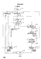
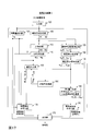
- FIG. 1 is a diagram illustrating the functional configuration of a conventional encoding device.
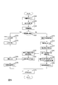
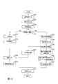
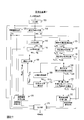
- FIG. 2 is a diagram illustrating the processing flow of the conventional encoding method.
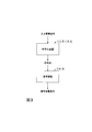
- FIG. 3 is a diagram illustrating the relationship between the encoding device and the decoding device.
- FIG. 4 is a diagram illustrating the functional configuration of the encoding device of the first embodiment.
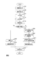
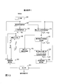
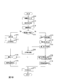
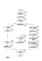
- FIG. 5 is a diagram illustrating the processing flow of the encoding method of the first embodiment.
- FIG. 6 is a diagram illustrating a functional configuration of the decoding device of the first embodiment.
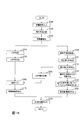
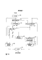
- FIG. 7 is a diagram illustrating the processing flow of the decoding method of the first embodiment.
- FIG. 8 is a diagram illustrating a functional configuration of the coding device according to the second embodiment.
- FIG. 1 is a diagram illustrating the functional configuration of a conventional encoding device.
- FIG. 2 is a diagram illustrating the processing flow of the conventional encoding method.
- FIG. 3 is a diagram illustrating the relationship between the
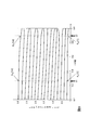
- FIG. 9 is a diagram for explaining the nature of LSP parameters.
- FIG. 10 is a diagram for explaining the nature of LSP parameters.
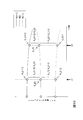
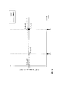
- FIG. 11 is a diagram for explaining the nature of LSP parameters.
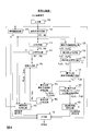
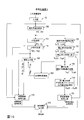
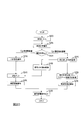
- FIG. 12 is a diagram illustrating the processing flow of the encoding method of the second embodiment.
- FIG. 13 is a diagram illustrating the functional configuration of the decoding device according to the second embodiment.
- FIG. 14 is a diagram illustrating the processing flow of the decoding method of the second embodiment.
- FIG. 15 is a diagram illustrating a functional configuration of a coding device according to a modification of the second embodiment.
- FIG. 16 is a diagram illustrating the processing flow of the encoding method of the modification of the second embodiment.
- FIG. 17 is a diagram illustrating a functional configuration of the coding device according to the third embodiment.
- FIG. 18 is a diagram illustrating the processing flow of the encoding method of the third embodiment.
- FIG. 19 is a diagram illustrating a functional configuration of the decoding device of the third embodiment.
- FIG. 20 is a diagram illustrating the processing flow of the decoding method of the third embodiment.
- FIG. 21 is a diagram illustrating a functional configuration of the coding device according to the fourth embodiment.
- FIG. 22 is a diagram illustrating the processing flow of the encoding method of the fourth embodiment.
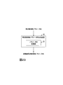
- FIG. 23 is a diagram illustrating the functional configuration of the frequency domain parameter sequence generator of the fifth embodiment.
- the encoding apparatus encodes a LSP parameter converted from a linear prediction coefficient in a frame that performs encoding in the time domain to obtain an LSP code, and corrects a frame that performs encoding in the frequency domain.
- LSP parameter converted from the calculated linear prediction coefficient to obtain the corrected LSP code and performing encoding in the time domain in the frame following the frame encoded in the frequency domain.
- What converted the linear prediction coefficient obtained by reversely correcting the linear prediction coefficient corresponding to the LSP parameter corresponding to the corrected LSP code into LSP is used as the LSP parameter used in the coding in the time domain of the next frame is there.
- the decoding apparatus obtains linear prediction coefficients converted from LSP parameters obtained by decoding LSP codes in a frame that performs decoding in the time domain, and uses them for decoding in the time domain.
- the corrected LSP parameter obtained by decoding the corrected LSP code is used for decoding in the frequency domain, and the decoding in the time domain is performed in the next frame of the frame decoded in the frequency domain
- the linear prediction coefficients obtained by reversely correcting the linear prediction coefficients corresponding to the LSP parameters corresponding to the corrected LSP code are converted into LSPs to be the LSP parameters used in the decoding in the time domain of the next frame It is.
- the input acoustic signal input to the encoding device 1 is encoded into a code string, and the code string is decoded from the encoding device 1 2, and the code string is decoded into a decoded acoustic signal by the decoding device 2 and output.
- the encoding device 1 has an input unit 100, a linear prediction analysis unit 105, an LSP generation unit 110, an LSP encoding unit 115, a feature extraction unit 120, as in the conventional encoding device 9.
- it further includes a linear prediction coefficient correction unit 125, a corrected LSP generation unit 130, a corrected LSP coding unit 135, and a frequency domain coding unit 150, a delay input unit 165, a time domain coding unit 170 and an output unit 175.
- a quantized linear prediction coefficient generation unit 140, a first quantized smoothed power spectrum envelope sequence calculation unit 145, a quantized linear prediction coefficient inverse correction unit 155, and an inverse corrected LSP generation unit 160 are included.
- the encoding device 1 is a special program configured by reading a special program into a known or dedicated computer having a central processing unit (CPU), a main memory (Random Access Memory, RAM), etc. Device.
- the encoding device 1 executes each process, for example, under the control of a central processing unit.
- the data input to the encoding device 1 and the data obtained by each process are stored, for example, in the main storage device, and the data stored in the main storage device is read as necessary and used for other processes. Be done.
- at least a part of each processing unit of the encoding device 1 may be configured by hardware such as an integrated circuit.
- the linear prediction coefficient sequence a [1], a [2],..., A [p] is a sequence obtained by converting it into LSP parameters, LSP parameter sequence ⁇ [1], ⁇ [2 ], ..., ⁇ [p] instead of encoding the LSP code C1, instead of using the corrected linear prediction coefficient sequence a ⁇ R [1], a ⁇ R [2], ..., a ⁇ R [p] as LSP parameters
- the corrected LSP code sequence C ⁇ is output by encoding the converted sequence of corrected LSP parameter strings ⁇ ⁇ R [1], ⁇ ⁇ R [2],..., ⁇ ⁇ R [p].
- the feature quantity extracted by the feature quantity extraction unit 120 in the previous frame is smaller than a predetermined threshold (that is, when the time variation of the input acoustic signal is small)
- a predetermined threshold that is, when the time variation of the input acoustic signal is small
- the quantized linear prediction coefficient inverse correction unit 155 and the inverse correction LSP generation unit 160 are processing units added for that, and when the feature quantity extracted by the feature quantity extraction unit 120 in the previous frame is smaller than a predetermined threshold value (That is, when the time variation of the input acoustic signal is small), the time from the corrected quantized linear prediction coefficient sequence ⁇ a ⁇ R [1], ⁇ a ⁇ R [2], ..., ⁇ a ⁇ R [p]
- a predetermined threshold value That is, when the time variation of the input acoustic signal is small
- the inversely corrected LSP parameter string ⁇ ⁇ '[1], ⁇ ⁇ ' [2], ..., ⁇ ⁇ '[p] is a quantized LSP parameter string ⁇ ⁇ [1], ⁇ ⁇ [2], ..., ⁇ ⁇ [p] is a series of approximate values.
- step S125 the linear prediction coefficient correction unit 125 calculates each coefficient a [i] (i of the linear prediction coefficient sequence a [1], a [2], ..., a [p] output from the linear prediction analysis unit 105.
- a series of coefficients a ⁇ R [i] a [i] ⁇ ⁇ R i obtained by multiplying the correction coefficient ⁇ R to the i-th power is calculated and output.
- the determined series a ⁇ R [1], a ⁇ R [2], ..., a ⁇ R [p] is referred to as a corrected linear prediction coefficient sequence.
- the corrected linear prediction coefficient sequence a ⁇ R [1], a ⁇ R [2],..., A ⁇ R [p] output from the linear prediction coefficient correction unit 125 is input to the corrected LSP generation unit 130.
- the corrected LSP generation unit 130 corresponds to the corrected linear prediction coefficient sequence a ⁇ R [1], a ⁇ R [2], ..., a ⁇ R [p] output from the linear prediction coefficient correction unit 125.
- the corrected LSP parameter string ⁇ ⁇ R [1], ⁇ ⁇ R [2],..., ⁇ ⁇ R [p] is a series arranged in ascending order of values. In other words, 0 ⁇ ⁇ R [1] ⁇ ⁇ R [2] ⁇ ... ⁇ ⁇ R [p] ⁇ Meet.
- the corrected LSP parameter strings ⁇ ⁇ R [1], ⁇ ⁇ R [2],..., ⁇ ⁇ R [p] output from the corrected LSP generating unit 130 are input to the corrected LSP encoding unit 135.
- the corrected LSP encoding unit 135 encodes the corrected LSP parameter string ⁇ ⁇ R [1], ⁇ ⁇ R [2],..., ⁇ ⁇ R [p] output from the corrected LSP generating unit 130.
- a corrected LSP code C ⁇ and a series of quantized corrected LSP parameters corresponding to the corrected LSP code C ⁇ ⁇ ⁇ ⁇ R [1], ⁇ ⁇ ⁇ R [2], ..., ⁇ ⁇ ⁇ R [p] Output.
- the series ⁇ ⁇ R [1], ⁇ ⁇ R [2], ..., ⁇ ⁇ R [p] will be referred to as a corrected quantized LSP parameter sequence.
- the corrected quantized LSP parameter string ⁇ ⁇ ⁇ R [1], ⁇ ⁇ ⁇ R [2], ..., ⁇ ⁇ ⁇ R [p] output from the corrected LSP coding unit 135 is a quantized linear prediction coefficient generation unit It is input to 140.
- the corrected LSP code C ⁇ output from the corrected LSP coding unit 135 is input to the output unit 175.
- step S140 the quantized linear prediction coefficient generation unit 140 outputs the corrected quantized LSP parameter string ⁇ ⁇ ⁇ R [1], ⁇ ⁇ ⁇ R [2], ..., which is output from the corrected LSP encoding unit 135.
- ⁇ ⁇ ⁇ R [p] from the linear prediction coefficient series ⁇ a ⁇ R [1], ⁇ a ⁇ R [2], ..., ⁇ a ⁇ R generates and outputs [p].
- the sequence ⁇ a ⁇ R [1], ⁇ a ⁇ R [2], ..., ⁇ a ⁇ R [p] is called a corrected quantized linear prediction coefficient sequence.
- the corrected quantized linear prediction coefficient sequence ⁇ a ⁇ [1], ⁇ a ⁇ [2], ..., ⁇ a ⁇ [p] output from the quantized linear prediction coefficient generation unit 140 is first quantized
- the signal is input to the smoothed power spectrum envelope sequence calculator 145 and the quantized linear prediction coefficient inverse corrector 155.
- step S145 the first quantized smoothed power spectrum envelope sequence calculating unit 145 calculates the corrected quantized linear prediction coefficient sequence ⁇ a ⁇ R [1], which is output from the quantized linear prediction coefficient generating unit 140. Using the coefficients ⁇ a ⁇ R [i] of ⁇ a ⁇ R [2], ..., ⁇ a ⁇ R [p], the quantized smoothed power spectrum envelope sequence ⁇ W ⁇ R [1] , ⁇ W ⁇ R [2], ..., ⁇ W ⁇ R [N] is generated and output.
- the quantized smoothed power spectrum envelope sequence ⁇ W ⁇ R [1], ⁇ W ⁇ R [2], ..., ⁇ W ⁇ R [N] output from the first quantized smoothed power spectrum envelope series calculation unit 145 ] Is input to the frequency domain coding unit 150.
- the process of the frequency domain coding unit 150 is smoothed and quantized in place of the approximate smoothed power spectrum envelope sequence ⁇ W ⁇ R [1], ⁇ W ⁇ R [2], ... ⁇ W ⁇ R [N].
- step S 155 the quantized linear prediction coefficient inverse correction unit 155 outputs the corrected quantized linear prediction coefficient sequence ⁇ a ⁇ R [1], ⁇ a ⁇ R [2] output from the quantized linear prediction coefficient generation unit 140. ], ..., ⁇ a ⁇ R [p] values ⁇ a ⁇ R [i] divided by the power of correction coefficient ⁇ R a ⁇ [i] / ( ⁇ R) i series ⁇ a ⁇ [1] / ( ⁇ R), ⁇ a ⁇ [2] / ( ⁇ R) 2 ,..., ⁇ a ⁇ [p] / ( ⁇ R) p is determined and output.
- sequence ⁇ a ⁇ [1] / ( ⁇ R), ⁇ a ⁇ [2] / ( ⁇ R) 2, ..., ⁇ a ⁇ [p] / ( ⁇ R) p inverse corrected linear prediction coefficient string Call it
- the correction coefficient ⁇ R has the same value as the correction coefficient ⁇ R used in the linear prediction coefficient correction unit 125.
- step S160 the inverse corrected LSP generator 160, output from the quantized linear prediction coefficient inverse correction section 155 inverse-corrected linear prediction coefficient string ⁇ a ⁇ [1] / ( ⁇ R), ⁇ a ⁇ [2 Find the sequence of LSP parameters ⁇ ⁇ '[1], ⁇ ⁇ ' [2], ..., ⁇ ⁇ '[p] from p] / ( ⁇ R) 2 , ..., ⁇ a ⁇ [p] / ( ⁇ R) p Output.
- the sequence ⁇ ⁇ ′ [1], ⁇ ⁇ ′ [2],..., ⁇ ⁇ ′ [p] of LSP parameters is called an inverse-corrected LSP parameter sequence.
- the inverse corrected LSP parameter string ⁇ ⁇ '[1], ⁇ ⁇ ' [2], ..., ⁇ ⁇ '[p] is a series arranged in ascending order of values. In other words, 0 ⁇ ⁇ '[1] ⁇ ⁇ ' [2] ⁇ ... ⁇ ⁇ '[p] ⁇ Is a series that satisfies
- the inverse corrected LSP parameters ⁇ ⁇ '[1], ⁇ ⁇ ' [2], ..., ⁇ ⁇ '[p] output from the inverse corrected LSP generation unit 160 are quantized LSP parameter strings ⁇ ⁇ [1] , ⁇ [2],..., ⁇ ⁇ [p] are input to the delay input unit 165. That is, the quantized LSP parameter sequence ⁇ ⁇ [1], ⁇ ⁇ [2], ..., ⁇ ⁇ [p] is inversely corrected LSP parameter ⁇ ⁇ '[1], ⁇ ⁇ ' [2], ..., ⁇ Substitute by ⁇ '[p].
- step S175 the encoding device 1 outputs the LSP code C1 output from the LSP encoding unit 115, the identification code Cg output from the feature amount extraction unit 120, and the corrected LSP encoding unit 135 via the output unit 175. And the frequency domain signal code output from the frequency domain coding unit 150 or the time domain signal code output from the time domain coding unit 160 are transmitted to the decoding device 2.
- the decoding device 2 has an input unit 200, an identification code decoding unit 205, an LSP code decoding unit 210, a corrected LSP code decoding unit 215, a decoded linear prediction coefficient generation unit 220, and a first decoded smoothed result.
- a power spectrum envelope sequence calculation unit 225, a frequency domain decoding unit 230, a decoded linear prediction coefficient inverse correction unit 235, a decoded inverse corrected LSP generation unit 240, a delay input unit 245, a time domain decoding unit 250, and an output unit 255 are included.
- the decryption device 2 is a special program configured by reading a special program into a known or dedicated computer having a central processing unit (CPU), a main memory (Random Access Memory, RAM), etc. It is an apparatus.
- the decoding device 2 executes each process, for example, under the control of the central processing unit.
- the data input to the decryption device 2 and the data obtained by each process are stored, for example, in the main storage device, and the data stored in the main storage device is read as necessary and used for other processes. Ru.
- at least a part of each processing unit of the decoding device 2 may be configured by hardware such as an integrated circuit.
- step S200 the code string generated by the coding device 1 is input to the decoding device 2.
- the code string includes an LSP code C1, an identification code Cg, a corrected LSP code C ⁇ , and either a frequency domain signal code or a time domain signal code.
- step S205 if the identification code Cg included in the input code string corresponds to the information indicating the frequency domain encoding method, the identification code decoding unit 205 executes the following process. If the identification code Cg corresponds to the information indicating the time domain coding method, the LSP code decoding unit 210 is controlled to execute the following processing.
- the generation unit 240 is executed when the identification code Cg included in the input code string corresponds to the information indicating the frequency domain coding method (step S206).
- step S215 the corrected LSP code decoding unit 215 decodes the corrected LSP code C ⁇ included in the input code string, and the decoded and corrected LSP parameter string ⁇ ⁇ R [1], ⁇ ⁇ ⁇ R [2], ..., ⁇ ⁇ ⁇ R [p] is obtained and output. That is, a decoded and corrected LSP parameter string ⁇ ⁇ R [1], ⁇ ⁇ R [2], ..., ⁇ ⁇ R [p], which is a string of LSP parameters corresponding to the corrected LSP code C ⁇ , is obtained and output.
- the corrected LSP code C ⁇ output from the encoding device 1 is a code error, etc.
- the decoded and corrected LSP parameter string ⁇ ⁇ ⁇ R [1], ⁇ ⁇ ⁇ R [2], ..., ⁇ ⁇ ⁇ R [p] output from the corrected LSP code decoding unit 215 is input to the decoded linear prediction coefficient generation unit 220. Ru.
- the decoded linear prediction coefficient generation unit 220 is linear from the decoded and corrected LSP parameter string ⁇ ⁇ ⁇ R [1], ⁇ ⁇ ⁇ R [2], ..., ⁇ ⁇ ⁇ R [p] output from the corrected LSP code decoding unit 215. Generate and output a series of prediction coefficients ⁇ a ⁇ R [1], ⁇ a ⁇ R [2], ..., ⁇ a ⁇ R [p].
- the sequence ⁇ a ⁇ R [1], ⁇ a ⁇ R [2], ..., ⁇ a ⁇ R [p] is called a decoding-corrected linear prediction coefficient sequence.
- the decoded linear prediction coefficient sequence ⁇ a ⁇ R [1], ⁇ a ⁇ R [2], ..., ⁇ a ⁇ R [p] output from the decoded linear prediction coefficient generation unit 220 is the first decoded smoothed power spectrum envelope sequence calculation It is input to the section 225 and the decoded linear prediction coefficient inverse correction section 235.
- the first decoded smoothed power spectrum envelope sequence calculation unit 225 calculates the decoded corrected linear prediction coefficient sequence ⁇ a ⁇ R [1], ⁇ a ⁇ R [2], ..., ⁇ output from the decoded linear prediction coefficient generation unit 220.
- Decoded smoothed power spectrum envelope sequence ⁇ W ⁇ R [1], ⁇ W ⁇ R [2], ..., ⁇ W by using equation (8) using each coefficient ⁇ a ⁇ R [i] of a ⁇ R [p] Generate and output ⁇ R [N].
- Decoded smoothed power spectrum envelope sequence ⁇ W ⁇ R [1], ⁇ W ⁇ R [2], ..., ⁇ W ⁇ R [N] output from first decoded smoothed power spectrum envelope sequence calculating section 225 is the frequency domain It is input to the decoding unit 230.
- step S235 the decoded linear prediction coefficient inverse correction unit 235 performs decoding-corrected linear prediction coefficient sequence ⁇ a ⁇ R [1], ⁇ a ⁇ R [2], ..., ⁇ a output from the decoded linear prediction coefficient generation unit 220.
- the correction coefficient ⁇ R has the same value as the correction coefficient ⁇ R used in the linear prediction coefficient correction unit 125 of the encoding device 1.
- step S240 the decoded inverse corrected LSP generating unit 240 generates the decoded inverse corrected linear prediction coefficient sequence ⁇ a ⁇ R [1] / ( ⁇ R), ⁇ a ⁇ R [2] / ( ⁇ R) 2 , ..., ⁇ a ⁇ R [p] / ( ⁇ R) p from the LSP parameter sequence ⁇ ⁇ '[1], ⁇ ⁇ ' [2], ..., ⁇ ⁇ ' output in search of [p].
- the sequence ⁇ ⁇ ′ [1], ⁇ ⁇ ′ [2],..., ⁇ ⁇ ′ [p] of LSP parameters is referred to as a decoding inverse-corrected LSP parameter sequence.
- the decoded inverse corrected LSP parameters ⁇ ⁇ '[1], ⁇ ⁇ ' [2], ..., ⁇ ⁇ '[p] output from the decoded inverse corrected LSP generating unit 240 are the decoded LSP parameter string ⁇ ⁇ [1] , ⁇ [2],..., ⁇ ⁇ [p] are input to the delay input unit 245.
- the LSP code decoding unit 210, the delay input unit 245, and the time domain decoding unit 250 are executed when the identification code Cg included in the input code string corresponds to the information indicating the time domain coding method (step S206). .
- step S210 the LSP code decoding unit 210 decodes the LSP code C1 included in the input code string and decodes the decoded LSP parameter string ⁇ ⁇ [1], ⁇ ⁇ [2], ..., ⁇ ⁇ [p]. Obtain and output. That is, the decoded LSP parameter string ⁇ ⁇ [1], ⁇ ⁇ [2], ..., ⁇ ⁇ [p], which is a string of LSP parameters corresponding to the LSP code C1, is obtained and output.
- Decoded LSP parameter sequences ⁇ ⁇ [1], ⁇ ⁇ [2],..., ⁇ ⁇ [p] output from the LSP code decoding unit 210 are input to the delay input unit 245 and the time domain decoding unit 250.
- step S245 the delay input unit 245 holds the input decoded LSP parameter string ⁇ ⁇ [1], ⁇ ⁇ [2], ..., ⁇ ⁇ [p], and delays by one frame to obtain a time domain. It is output to the encoding unit 250. For example, if the current frame is the f-th frame, the decoded LSP parameter string ⁇ ⁇ [f-1] [1], ⁇ ⁇ [f-1] [2], ..., ⁇ of the f-1st frame [ theta ] [f-1] [p] is output to time domain encoding section 250.
- the decoding reverse corrected LSP parameter string ⁇ ⁇ ′ output from the decoding reverse corrected LSP generation unit 240 [1], ⁇ ⁇ '[2], ..., ⁇ ⁇ ' [p] are input to the delay input unit 245 as the decoded LSP parameter string ⁇ ⁇ [1], ⁇ ⁇ [2], ..., ⁇ ⁇ [p] Be done.
- step S250 the time domain decoding unit 250 specifies the waveform included in the adaptive codebook and the waveform included in the fixed codebook from the time domain signal code included in the input code string.
- a synthesis filter is applied to a signal obtained by synthesizing the waveform contained in the specified adaptive codebook and the waveform contained in the fixed codebook to obtain a synthesized signal from which the influence of the spectral envelope has been removed, and the obtained synthesized signal as a decoded acoustic signal Output.
- Filter coefficients of the synthesis filter is decoded LSP parameter sequence of f-th frame ⁇ ⁇ [1], ⁇ ⁇ [2], ..., ⁇ ⁇ [p] and f-1-th frame of the decoded LSP parameter sequence ⁇ theta [ f-1] [1], ⁇ ⁇ [f-1] [2], ..., ⁇ ⁇ [f-1] [p].
- the frame is divided into two subframes, and the filter coefficients of the synthesis filter are determined as follows.
- a coefficient obtained by converting the decoded LSP parameter string ⁇ ⁇ [1], ⁇ ⁇ [2], ..., ⁇ ⁇ [p] of the f-th frame into linear prediction coefficients A series of values obtained by multiplying each coefficient ⁇ a [i] of decoded linear prediction coefficients ⁇ a [1], ⁇ a [2], ..., ⁇ a [p], which are columns, by the power of correction coefficient ⁇ R i 1] ⁇ ( ⁇ R), ⁇ a [2] ⁇ ( ⁇ R) 2 ,..., ⁇ A [p] ⁇ ( ⁇ R) p
- the filter coefficients of the synthesis filter include the values of the decoded LSP parameter string ⁇ ⁇ [1], ⁇ ⁇ [2], ..., ⁇ ⁇ [p] of the f-th frame ⁇ ⁇ [i] And f-1 th frame of decoded LSP parameter sequence ⁇ [f-1] [1], ⁇ [f-1] [2], ..., ⁇ [f-1] [p] each value ⁇ ⁇ [f -1]
- ⁇ [p] which is a series of values intermediate to [i], into linear prediction coefficients A sequence of values obtained by multiplying each coefficient to a [i] of a certain decoded interpolated linear prediction coefficient to a [1], to a [2], ..., to a [p] by the power of the correction coefficient ⁇ R i to a [ 1] ⁇ ( ⁇ R), ⁇ a [2] ⁇ ( ⁇ R) 2 ,..., ⁇ A [p] ⁇ ( ⁇ R) p
- the corrected LSP coding unit 135 of the coding device 1 the corrected LSP parameter string ⁇ ⁇ R [1], ⁇ ⁇ R [2],..., ⁇ ⁇ R [p] and the corrected quantized LSP parameter string ⁇ ⁇ ⁇ R [1], ⁇ ⁇ ⁇ R [2], ..., ⁇ ⁇ ⁇ R [p] corrected quantized LSP parameter sequence that minimizes quantization distortion ⁇ ⁇ ⁇ R [1], ⁇ ⁇ ⁇ R [2] ], ..., ⁇ ⁇ ⁇ R [p] is obtained.
- the corrected quantized LSP parameter string ⁇ ⁇ ⁇ R [1], ⁇ ⁇ ⁇ R [1], so as to approximate with high precision the power spectrum envelope sequence in which aural sensation is taken into consideration (that is, smoothed by the correction coefficient ⁇ R). 2], ..., ⁇ ⁇ ⁇ R [p] can be determined.
- Quantized smoothing is a power spectrum envelope series obtained by expanding the corrected quantized LSP parameter sequence ⁇ ⁇ ⁇ R [1], ⁇ ⁇ ⁇ R [2], ..., ⁇ ⁇ ⁇ R [p] in the frequency domain
- Power spectrum envelope sequence ⁇ W ⁇ R [1], ⁇ W ⁇ R [2], ..., ⁇ W ⁇ R [N] is a smoothed power spectrum envelope sequence W ⁇ R [1], W ⁇ R [2], ..., W ⁇ R [N] can be approximated with high accuracy. If the code amounts of the LSP code C1 and the corrected LSP code C ⁇ are the same, the first embodiment can make the coding distortion of the coding in the frequency domain smaller than in the prior art.
- the code amount of the corrected LSP code C ⁇ is smaller than that of the conventional LSP code C1. Therefore, if the coding distortion is the same as in the conventional case, the code amount can be made smaller than in the conventional case, and if it is the same code amount as in the conventional case, the coding distortion can be made smaller than in the conventional case.
- the encoding device 1 and the decoding device 2 of the first embodiment particularly, the calculation cost of the inverse corrected LSP generating unit 160 and the decoding inverse corrected LSP generating unit 240 is large. Therefore, in the coding device 3 of the second embodiment, the corrected quantized LSP parameter string ⁇ ⁇ ⁇ R [1], ⁇ ⁇ ⁇ R [2], ..., ⁇ ⁇ ⁇ R [2] without passing through linear prediction coefficients.
- Approximated quantized LSP parameter string ⁇ ⁇ [1] which is a series of approximate values of each value of quantized LSP parameter string ⁇ ⁇ [1], ⁇ ⁇ [2], ..., ⁇ ⁇ [p] from p] app , ⁇ ⁇ [2] app , ..., ⁇ ⁇ [p] Create app directly.
- Decoded LSP parameter string ⁇ ⁇ [1], ⁇ ⁇ [2], ..., ⁇ ⁇ [p] is a series of approximate values of each value Decoded approximate LSP parameter string ⁇ ⁇ [1] app , ⁇ ⁇ [2 ] app , ..., ⁇ ⁇ [p] Create app directly.
- FIG. 8 shows a functional configuration of the encoding device 3 of the second embodiment.
- the coding device 3 does not include the quantized linear prediction coefficient reverse correction unit 155 and the reverse correction LSP generation unit 160 as compared to the coding device 1 of the first embodiment, but includes the LSP linear conversion unit 300 instead. The point is different.
- LSP linear transformation unit 300 approximates the corrected quantized LSP parameter string ⁇ ⁇ ⁇ R [1], ⁇ ⁇ ⁇ R [2],..., ⁇ ⁇ ⁇ R [p] using the property of the LSP parameter.
- Linear transformation is performed to generate an approximate quantized LSP parameter sequence ⁇ ⁇ [1] app , ⁇ ⁇ [2] app , ..., ⁇ ⁇ [p] app .
- the LSP linear transformation unit 300 targets the quantized sequence of LSP parameters as a target of the approximate transformation
- the nature of the sequence of quantized LSP parameters is basically the same as the nature of the unquantized LSP parameter sequence. First, the nature of the unquantized LSP parameter sequence will be described.
- LSP parameter sequences ⁇ [1], ⁇ [2],..., ⁇ [p] are frequency domain parameter sequences that are correlated with the power spectrum envelope of the input acoustic signal. Each value of the LSP parameter sequence is correlated with the frequency position of the extremum of the power spectrum envelope of the input acoustic signal.
- the extremum of the power spectrum envelope exists at the frequency position between ⁇ [i] and ⁇ [i + 1], and the steepness of the tangent line around this extremum is ⁇ [i] and ⁇ [i + 1) (that is, the value of ⁇ [i + 1] ⁇ [i]) decreases.
- ⁇ 1
- ⁇ ⁇ 1 [2]
- ⁇ ⁇ 1 [p]
- LSP parameter string ⁇ [1], ⁇ [ 2], ..., ⁇ [p] are equivalent.
- the corrected LSP parameter is 0 ⁇ ⁇ [1] ⁇ ⁇ [2] ... ⁇ ⁇ [p] ⁇ Meet the nature of
- the horizontal axis represents the value of the correction coefficient ⁇
- the vertical axis represents the value of the corrected LSP parameter.
- linear prediction coefficient correction is performed using a linear prediction coefficient sequence a [1], a [2],..., A [p] obtained by performing linear prediction analysis on a certain audio sound signal
- each LSP parameter ⁇ ⁇ [i] has a linear relationship to increase or decrease of ⁇ when viewed locally It is in.
- the size of LSP is the LSP parameters before and after ⁇ ⁇ 1 [i] in the LSP parameter string ⁇ ⁇ 1 [1], ⁇ ⁇ 1 [2], ..., ⁇ ⁇ 1 [p] (that is, ⁇ ⁇ 1 [i-1]
- Equation (9) (10) in the case of ⁇ ⁇ 1 [i] is ⁇ ⁇ 1 [i + 1] and theta .gamma.1 than the midpoint of the [i-1] ⁇ ⁇ 1 [ i + 1] pro, theta .gamma.2 [ i] further indicates that the value is closer to ⁇ ⁇ 2 [i + 1] (see FIG. 10).
- a point (0, ⁇ ⁇ 0 [i]) and a point ( ⁇ 1, ⁇ ⁇ 1 [i]) on a two-dimensional plane with the horizontal axis as ⁇ and the vertical axis as LSP parameter.
- the slope of the straight line L2 connecting the point ( ⁇ 1, ⁇ ⁇ 1 [i]) and the point ( ⁇ 2, ⁇ ⁇ 2 [i]) is larger than the slope of the connecting straight line L1 (see FIG. 11).
- Equation (11) (12) the ⁇ ⁇ 1 [i] is ⁇ ⁇ 1 [i + 1] and ⁇ ⁇ 1 [i-1]
- theta .gamma.2 [ i] further indicates that the value is closer to ⁇ ⁇ 2 [i-1].
- a point (0, ⁇ ⁇ 0 [i]) and a point ( ⁇ 1, ⁇ ⁇ 1 [i]) on a two-dimensional plane with the horizontal axis as ⁇ and the vertical axis as LSP parameter.
- the slope of the straight line connecting the point ( ⁇ 1, ⁇ ⁇ 1 [i]) and the point ( ⁇ 2, ⁇ ⁇ 2 [i]) is smaller than the slope of the connecting straight line.
- equations (9) to (12) the relationship is described on the assumption that ⁇ 1 ⁇ 2, but in the model of equation (13), there is no limitation on the magnitude relationship between ⁇ 1 and ⁇ 2, and even if ⁇ 1 ⁇ 2, ⁇ 1> It may be ⁇ 2.
- the matrix K is a band matrix having only non-zero values for diagonal components and elements in the vicinity thereof, and is a matrix representing the above-mentioned correlation that holds between LSP parameters corresponding to the diagonal components and LSP parameters adjacent thereto. It is.
- the band matrix of the bandwidth 3 was illustrated in Formula (14), a bandwidth is not limited to three.
- ⁇ ⁇ ⁇ 2 ( ⁇ ⁇ ⁇ 2 [1], ⁇ ⁇ ⁇ 2 [2], ..., ⁇ ⁇ ⁇ 2 [p]) T Is an approximation of ⁇ ⁇ 2 .
- equation (15) can be rewritten as follows.
- ⁇ ⁇ 2 [1], ⁇ ⁇ 2 [2], ... ⁇ ⁇ 2 [p] obtained by the equation (13a) is a linear prediction coefficient sequence a [1] ⁇ ( ⁇ 2), ..., a [p ] X ( ⁇ 2) It is an approximate value (estimated value) of values ⁇ ⁇ 2 [1], ⁇ ⁇ 2 [2],..., ⁇ ⁇ 2 [p] of LSP parameters when p is converted to LSP parameters.
- the matrix K of the equation (14) has a positive value in the diagonal component, and the element in the vicinity is negative Tends to have a value of.
- the matrix K is a matrix set in advance, and for example, one that has been learned in advance using learning data is used.
- the learning method of the matrix K will be described later.
- Equations (13), (13a), and (13b) are very small.
- the LSP linear transformation unit 300 included in the encoding device 3 of the second embodiment corrects the quantized LSP parameter sequence ⁇ ⁇ ⁇ R [1], ⁇ ⁇ ⁇ R [2], ..., based on the equation (13b). ⁇ ⁇ ⁇ R [p] from the approximate quantized LSP parameter sequence ⁇ ⁇ [1] app, ⁇ ⁇ [2] app, ..., ⁇ ⁇ to generate the [p] app.
- the correction coefficient ⁇ R used when generating the corrected quantized LSP parameter string ⁇ ⁇ R [1], ⁇ ⁇ ⁇ R [2], ..., ⁇ ⁇ ⁇ R [p] is the linear prediction coefficient correction unit 125 Are the same as the correction coefficient ⁇ R used in
- the processing of the corrected LSP coding unit 135 is the same as in the first embodiment. However, the corrected quantized LSP parameter string ⁇ ⁇ ⁇ R [1], ⁇ ⁇ ⁇ R [2],..., ⁇ ⁇ ⁇ R [p] output from the corrected LSP encoding unit 135 are quantized linear prediction coefficients. In addition to the generation unit 140, the signal is also input to the LSP linear conversion unit 300.
- the approximate quantized LSP parameter sequence ⁇ ⁇ [1] app , ⁇ ⁇ [2] app , ..., ⁇ ⁇ [p] app is determined and output. That is, a series ⁇ ⁇ [1] app , ⁇ ⁇ [2] app , ..., ⁇ ⁇ [p] app of approximate values of the quantized LSP parameter sequence is obtained using the equation (13b).
- the approximate quantized LSP parameter string ⁇ ⁇ [1] app , ⁇ ⁇ [2] app ,..., ⁇ ⁇ [p] app output from the LSP linear transformation unit 300 is the quantized LSP parameter string ⁇ ⁇ [1 ], ⁇ ⁇ [2],..., ⁇ ⁇ [p] are input to the delay input unit 165. That is, in the time domain encoding unit 170, when the feature quantity extracted by the feature quantity extracting unit 120 in the previous frame is smaller than a predetermined threshold (ie, when the time variation of the input acoustic signal is small), ie, in the frequency domain.
- a predetermined threshold ie, when the time variation of the input acoustic signal is small
- FIG. 13 shows a functional configuration of the decoding device 4 of the second embodiment.
- the decoding device 4 does not include the decoded linear prediction coefficient inverse correction unit 235 and the decoding inverse correction LSP generation unit 240, but instead includes the decoded LSP linear conversion unit 400. It is different.
- the processing of the corrected LSP code decoding unit 215 is the same as in the first embodiment. However, the decoded and corrected LSP parameter string ⁇ ⁇ ⁇ R [1], ⁇ ⁇ ⁇ R [2],..., ⁇ ⁇ ⁇ R [p] output from the corrected LSP code decoding unit 215 is sent to the decoded linear prediction coefficient generation unit 220. In addition, the decoded LSP linear transformation unit 400 is also input.
- the decoded approximate LSP parameter string ⁇ ⁇ [1] app , ⁇ ⁇ [2] app , ..., ⁇ ⁇ [p] app output from the decoded LSP linear transformation unit 400 is the decoded LSP parameter string ⁇ ⁇ [1], ⁇ It is input to the delay input unit 245 as ⁇ [2],..., ⁇ ⁇ [p].
- the decoded LSP parameter string ⁇ ⁇ [1] of the previous frame, ⁇ ⁇ [2] ], ..., ⁇ ⁇ [p] are substituted with the approximate quantized LSP parameter string ⁇ ⁇ [1] app , ⁇ ⁇ [2] app , ..., ⁇ ⁇ [p] app of the previous frame.
- the transformation matrix K used in the LSP linear transformation unit 300 and the decoding LSP linear transformation unit 400 is obtained in advance by the following method, and stored in a storage unit (not shown) in the encoding device 3 and the decoding device 4 Keep it.
- Step 1 With respect to sample data of speech sound signals of M frames prepared in advance, each sample data is subjected to linear prediction analysis to obtain linear prediction coefficients.
- the linear prediction coefficient sequence obtained by performing linear prediction analysis on the m-th (1 ⁇ m ⁇ M) sample data is a (m) [1], a (m) [2], ..., a (m) [p]
- Step 4 For each m, the corrected linear prediction coefficient sequence a ⁇ L (m) [1], ..., a ⁇ L (m) [p] to the corrected LSP parameter sequence ⁇ ⁇ L (m) [1], ..., Determine ⁇ ⁇ L (m) [p].
- the corrected LSP parameter string ⁇ ⁇ L (m) [1], ..., ⁇ ⁇ L (m) [p] is encoded in the same manner as the corrected LSP encoding unit 135, and the quantized LSP parameter string ⁇ ⁇ ⁇ L (m) [1], ..., ⁇ ⁇ ⁇ L (m) [p] is obtained.
- the matrix K used in the LSP linear transformation unit 300 may not be learned using the same value as the correction coefficient ⁇ R used in the encoding device 3.
- each element of the band part of matrix K obtained by the above method is multiplied by ( ⁇ 2- ⁇ 1), ie, the value of each element of the band part of matrix K ′ , Becomes as follows.
- a value obtained by multiplying each value of x 1 , x 2 , ..., x 15 , y 1 , y 2 , ..., y 14 , z 2 , z 3 , ..., z 15 in the equation (14) by ⁇ 2- ⁇ 1 are the following xx 1 , xx 2 , ..., xx 15 , yy 1 , yy 2 , ..., yy 14 , zz 2 , zz 3 , ..., zz 15 .
- the matrix K ′ takes a value close to 1 as the diagonal component as in the above example and is adjacent to the diagonal matrix
- the component to be taken takes a negative value.
- the matrix K ′ takes negative values for the diagonal components as in the following example, and components adjacent to the diagonal matrix take positive values.
- the coding device 3 of the second embodiment is the quantized linear prediction coefficient generation unit 900, the quantized linear prediction coefficient correction unit 905, and the approximate smoothed configuration in the conventional coding device 9.
- the power spectrum envelope sequence calculation unit 910 includes a linear prediction coefficient correction unit 125, a corrected LSP generation unit 130, a corrected LSP coding unit 135, a quantized linear prediction coefficient generation unit 140, and a first quantized smoothed power. Since the configuration is replaced with the spectrum envelope sequence calculation unit 145, the same effect as the coding device 1 of the first embodiment is obtained. That is, if the coding distortion is the same as in the conventional case, the code amount can be made smaller than in the conventional case, and if it is the same code amount as in the conventional case, the coding distortion can be made smaller than in the conventional case.
- the quantized LSP can be calculated with a smaller amount of operation than that of the first embodiment.
- a series of approximate values of the parameter sequence ⁇ ⁇ [1], ⁇ ⁇ [2], ..., ⁇ ⁇ [p] can be generated.
- Second Embodiment it is determined for each frame whether encoding in the time domain or encoding in the frequency domain is to be performed based on the magnitude of the time variation of the input acoustic signal. There is. Even in a frame in which temporal variation of the input acoustic signal is large and encoding in the time domain is selected, the acoustic signal reconstructed by encoding in the time domain is actually reconstructed by encoding in the frequency domain. In some cases, distortion with the input acoustic signal can be made smaller than that of the signal.
- the encoding device 8 of the modification of the second embodiment performs both encoding in the time domain and encoding in the frequency domain for each frame to reduce distortion with the input acoustic signal. select.
- FIG. 15 shows a functional configuration of the encoding device 8 of the modification of the second embodiment.
- the encoding device 8 differs from the encoding device 3 of the second embodiment in that it does not include the feature quantity extraction unit 120 and includes a code selection output unit 375 instead of the output unit 175.
- the LSP generation unit 110 in addition to the input unit 100 and the linear prediction analysis unit 105, the LSP generation unit 110, the LSP coding unit 115, the linear prediction coefficient correction unit 125, and the corrected LSP generation unit 130.
- the corrected LSP coding unit 135, the quantized linear prediction coefficient generation unit 140, the first quantized smoothed power spectrum envelope sequence calculation unit 145, the delay input unit 165, and the LSP linear conversion unit 300 are also input acoustic signals. It is performed for all frames regardless of whether the time variation of the signal is large or small. The operations of these units are the same as in the second embodiment. However, the approximate quantized LSP parameter string ⁇ ⁇ [1] app , ⁇ ⁇ [2] app ,..., ⁇ ⁇ [p] app generated by the LSP linear transformation unit 300 is input to the delay input unit 165.
- the delay input unit 165 receives the quantized LSP parameter string ⁇ ⁇ [1], ⁇ ⁇ [2], ..., ⁇ ⁇ [p] input from the LSP coding unit 115 and the LSP linear transformation unit 300.
- the approximate quantized LSP parameter string ⁇ ⁇ [1] app , ⁇ ⁇ [2] app , ..., ⁇ ⁇ [p] app is held for at least one frame, and the code selection output unit 375 performs the frequency in the previous frame.
- the LSP linear transformation unit 300 Approximated quantized LSP parameter string ⁇ ⁇ [1] app , ⁇ ⁇ [2] app , ..., ⁇ ⁇ [p] app of the previous frame that has been input to the quantized LSP parameter string ⁇ ⁇ [of the previous frame 1], ⁇ ⁇ [2], ..., ⁇ ⁇ [p] and output to time domain encoding section 170, and code selection output section 3 in the previous frame
- the time domain coding method is selected in step 5 (ie, when the identification code Cg output from the code selection output unit 375 in the previous frame is information indicating the time domain coding method)
- LSP coding is performed.
- the quantized LSP parameter string ⁇ ⁇ [1], ⁇ ⁇ [2],..., ⁇ ⁇ [p] of the previous frame input from the unit 115 is output to the
- the frequency domain coding unit 150 generates and outputs a frequency domain signal code in the same manner as the frequency domain coding unit 150 of the second embodiment, and also generates distortion or no distortion of the input acoustic signal corresponding to the frequency domain signal code. Obtain and output an estimated value of distortion.
- the distortion and its estimated value may be determined in the time domain or in the frequency domain. That is, frequency domain encoding section 150 estimates distortion or distortion of the acoustic signal series in the frequency domain corresponding to the frequency domain signal code with respect to the acoustic signal series in the frequency domain obtained by converting the input acoustic signal into the frequency domain. You may ask for
- the time domain coding unit 170 generates and outputs a time domain signal code in the same manner as the time domain coding unit 170 of the second embodiment, and also generates distortion or no distortion of the sound signal corresponding to the time domain signal code with respect to the input sound signal. Determine an estimate of distortion.
- the code selection output unit 375 includes the frequency domain signal code generated by the frequency domain coding unit 150, the distortion or estimated value of distortion obtained by the frequency domain coding unit 150, and the time domain signal generated by the time domain coding unit 170.
- the code and the distortion or distortion estimation value obtained by the time domain coding unit 170 are input.
- code selection output unit 375 If the distortion or distortion estimation value input from frequency domain coding unit 150 is smaller than the distortion or distortion estimation value input from time domain coding unit 170, code selection output unit 375 generates a frequency domain signal. A code and an identification code Cg which is information indicating a frequency domain coding method are output, and the distortion or distortion estimated value input from the frequency domain coding unit 150 is the distortion or the distortion input from the time domain coding unit 170. If it is larger than the distortion estimated value, a time domain signal code and an identification code Cg which is information indicating a time domain coding method are output.
- the time domain signal code is determined according to a predetermined rule. While outputting one of the frequency domain signal codes, it outputs an identification code Cg which is information indicating a coding method corresponding to the code to be output. That is, among the frequency domain signal code input from frequency domain encoding section 150 and the time domain signal code input from time domain encoding section 170, distortion to the input acoustic signal of the acoustic signal reconstructed from the code is small. Is output, and information indicating an encoding method that reduces distortion is output as an identification code Cg (step S 375).
- the configuration may be such that the distortion with respect to the input acoustic signal of the acoustic signal reconstructed from the code is selected to be smaller.
- the frequency domain encoding unit 150 or the time domain encoding unit 170 reconstructs the acoustic signal from the code and outputs it instead of the distortion or the estimated value of the distortion.
- the code selection output unit 375 is an input sound among the frequency domain signal code and the time domain signal code, an acoustic signal reconstructed by the frequency domain encoding unit 150 and an acoustic signal reconstructed by the time domain encoding unit 170. While outputting the one where distortion with respect to a signal is smaller, the information which shows the encoding method with which distortion becomes small is output as identification code Cg.
- the configuration may be such that the smaller code amount is selected.
- the frequency domain encoding unit 150 outputs a frequency domain signal code as in the second embodiment.
- the time domain encoding unit 170 outputs a time domain signal code, as in the second embodiment.
- the code selection output unit 375 outputs the smaller one of the frequency domain signal code and the time domain signal code with the smaller code amount, and outputs the information indicating the coding method with the smaller code amount as the identification code Cg.
- ⁇ Decoding device> The code string output by the encoding device 8 of the modification of the second embodiment can be decoded by the decoding device 4 of the second embodiment, similarly to the code string output by the encoding device 3 of the second embodiment.
- the encoding device 8 of the modification of the second embodiment has the same effect as the encoding device 3 of the second embodiment, and further, the code amount to be output from the encoding device 3 of the second embodiment The effect is to reduce the
- the corrected quantized LSP parameter string ⁇ ⁇ ⁇ R [1], ⁇ ⁇ ⁇ R [2], ..., ⁇ ⁇ ⁇ R [p ] Is once converted to linear prediction coefficients, and then the quantized smoothed power spectrum envelope sequence ⁇ W ⁇ R [1], ⁇ W ⁇ R [2], ... ⁇ W ⁇ R [N] is calculated.
- the corrected quantized LSP parameter string ⁇ ⁇ ⁇ R [1], ⁇ ⁇ ⁇ R [2] without converting the corrected quantized LSP parameter string into linear prediction coefficients.
- FIG. 17 shows a functional configuration of the encoding device 5 of the third embodiment.
- the coding device 5 does not include the quantized linear prediction coefficient generation unit 140 and the first quantized smoothed power spectrum envelope sequence calculation unit 145 as compared to the coding device 3 of the second embodiment, and instead Is different in that the second quantized smoothed power spectrum envelope sequence calculator 146 is included.
- step S 146 the second quantized smoothed power spectrum envelope sequence calculating unit 146 calculates the corrected quantized LSP parameter ⁇ ⁇ ⁇ R [1], ⁇ ⁇ ⁇ R [5] output from the corrected LSP encoding unit 135. 2], ..., ⁇ ⁇ ⁇ R [p] and quantized smoothed power spectrum envelope sequence ⁇ W ⁇ R [1], ⁇ W ⁇ R [2], ..., ⁇ W ⁇ R [ Find and output N].
- FIG. 19 shows a functional configuration of the decoding device 6 of the third embodiment.
- the decoding device 6 does not include the decoded linear prediction coefficient generation unit 220 and the first decoded smoothed power spectrum envelope sequence calculation unit 225, and instead the second decoding smoothing Power spectrum envelope sequence calculation unit 226.
- step S226 the second decoded smoothed power spectrum envelope sequence calculating unit 226, similarly to the second quantized smoothed power spectrum envelope sequence calculating unit 146, decodes and corrects the corrected LSP parameter sequence ⁇ ⁇ ⁇ R [1]. , ⁇ ⁇ ⁇ R [2], ..., ⁇ ⁇ ⁇ R [p] using the above equation (19) to obtain the decoded smoothed power spectrum envelope sequence ⁇ W ⁇ R [1], ⁇ W ⁇ R [2], ..., ⁇ W ⁇ R [N] is obtained and output.
- the quantized LSP parameter sequence ⁇ ⁇ [1], ⁇ ⁇ [2], ..., ⁇ ⁇ [p] is 0 ⁇ ⁇ [1] ⁇ ... ⁇ ⁇ [p] ⁇ Is a series that satisfies That is, it is a series arranged in ascending order.
- the approximate quantized LSP parameter string ⁇ ⁇ [1] app , ⁇ ⁇ [2] app ,..., ⁇ ⁇ [p] app generated by the LSP linear transformation unit 300 are generated by approximate transformation. As it is, it may not be in ascending order.
- the approximate quantized LSP parameter string ⁇ ⁇ [1] app , ⁇ ⁇ [2] app , ..., ⁇ ⁇ [p] app output from the LSP linear transformation unit 300 are rearranged in ascending order.
- FIG. 21 shows a functional configuration of the encoding device 7 of the fourth embodiment.
- the encoding device 7 differs from the encoding device 5 of the second embodiment in that it further includes an approximate LSP sequence correction unit 700.
- the approximate LSP sequence correction unit 700 calculates the values of the approximate quantized LSP parameter string ⁇ ⁇ [1] app , ⁇ ⁇ [2] app , ..., ⁇ ⁇ [p] app output from the LSP linear transformation unit 300.
- the sequence obtained by rearranging ⁇ [i] app in ascending order is output as a corrected approximate quantized LSP parameter string ⁇ ⁇ '[1] app , ⁇ ⁇ ' [2] app , ..., ⁇ ⁇ '[p] app .
- the modified first approximate quantized LSP parameter string ⁇ ⁇ '[1] app , ⁇ ⁇ ' [2] app , ..., ⁇ ⁇ '[p] app output from the approximate LSP sequence modification unit 700 has been quantized.
- the LSP parameter string ⁇ ⁇ [1], ⁇ ⁇ [2], ..., ⁇ ⁇ [p] is input to the delay input unit 165.
- ISP parameter string ISP [1],..., ISP [p] is equivalent to a sequence composed of the p ⁇ 1 order LSP parameter string and the p order (highest order) PARCOR coefficient k p .
- ISP [p] k p It is.
- the input to the LSP linear transformation unit 300 is the corrected quantized ISP parameter string ⁇ ISP ⁇ R [1], ⁇ ISP ⁇ R [2], ..., ⁇ ISP ⁇ R [p].
- ⁇ ISP ⁇ R [1] ⁇ ⁇ ⁇ R [i]
- ISP ⁇ R [p] ⁇ k p It is.
- ⁇ k p is the quantized value of k p .
- the LSP linear transformation unit 300 obtains and outputs an approximately quantized ISP parameter string ⁇ ISP [1] app , ..., ISP [p] app according to the following processing.
- ⁇ ⁇ ⁇ 1 ( ⁇ ISP ⁇ R [1], ..., ⁇ ISP ⁇ R [p-1])
- T replace p with p-1, calculate equation (18), ⁇ ⁇ [1] app , ..., ⁇ ⁇ [p-1]
- Step 2 Find ⁇ ISP [p] app defined by the following equation.
- the frequency domain parameter string generator 10 includes, for example, a parameter string converter 20, and generates frequency domain parameters ⁇ [1], ⁇ [2], ..., ⁇ [p]. As input, the converted frequency domain parameters ⁇ ⁇ [1], ⁇ ⁇ [2], ... ⁇ ⁇ [p] are output.
- the input frequency domain parameters ⁇ [1], ⁇ [2],..., ⁇ [p] are linear prediction coefficients a [1], a [2] obtained by linear prediction analysis of the sound signal of a predetermined time interval. ], ..., a [p] are frequency domain parameter sequences.
- the frequency domain parameters ⁇ [1], ⁇ [2],..., ⁇ [p] are, for example, LSP parameter sequences ⁇ [1], ⁇ [2],..., ⁇ [p] used in the conventional coding method. It may be a quantized LSP parameter sequence ⁇ ⁇ [1], ⁇ ⁇ [2], ..., ⁇ ⁇ [p].
- the corrected LSP parameter string ⁇ ⁇ R [1], ⁇ ⁇ R [2],..., ⁇ ⁇ R [p] used in the above-described embodiments may be used, or the corrected quantized LSP parameter may be used. It may be the columns ⁇ ⁇ ⁇ R [1], ⁇ ⁇ ⁇ R [2], ..., ⁇ ⁇ ⁇ R [p]. Furthermore, it may be, for example, a frequency domain parameter equivalent to the LSP parameter, such as the ISP parameter string described in the above-mentioned modification. Further, frequency domain parameter sequences derived from linear prediction coefficients a [1], a [2],..., A [p] are linear prediction coefficient sequences a [1], a [2],.
- the ISP parameter string, the ISP parameter string, the LSF parameter string, the ISF parameter string, the frequency domain parameters ⁇ [1], ⁇ [2], ..., ⁇ [p-1] are all from 0 to ⁇
- the frequency domain parameters ⁇ [1], ⁇ [2]..., ⁇ [p ⁇ 1] are from 0 to ⁇ .
- a series of frequency domains derived from a linear prediction coefficient series, as represented by a frequency domain parameter series and the like present at equal intervals therebetween, and represented by the same number as the prediction order.
- the parameter sequence conversion unit 20 utilizes the property of the LSP parameters, as in the LSP linear conversion unit 300 and the decoded LSP linear conversion unit 400, to generate frequency domain parameter sequences ⁇ [1], ⁇ [2], ..., ⁇ [p. [1] approximately linear transformation is performed to generate a frequency domain parameter sequence ⁇ ⁇ [1], ⁇ ⁇ [2], ... ⁇ ⁇ [p] after transformation.
- the parameter string converter 20 obtains the value of the frequency domain parameter ⁇ [i] after conversion by any of the following methods.
- the value of the converted frequency domain parameter ⁇ ⁇ [i] is determined by linear transformation based on the relationship between the values of ⁇ [i] and one or more frequency domain parameters close to ⁇ [i]. For example, linear after the conversion of the frequency domain parameter string ⁇ ⁇ [i] after conversion to the frequency domain parameter string ⁇ [i] so that the parameter value spacing becomes closer to or even from the uniform spacing. Convert.
- the linear transformation to make it close to the even interval corresponds to the processing for smoothing the unevenness of the amplitude of the power spectrum envelope in the frequency domain (processing for smoothing the power spectrum envelope). Further, the linear transformation to make it far from the uniform interval corresponds to a process of emphasizing the unevenness of the amplitude of the power spectrum envelope in the frequency domain (a process of inversely smoothing the power spectrum envelope).
- the parameter string conversion unit 20 obtains and outputs the converted frequency domain parameters ⁇ [1], ⁇ [2],..., ⁇ [p] by the following equation (20).
- T Can be derived.
- the frequency domain parameters ⁇ [1], ⁇ [2],..., ⁇ [p] are linear prediction coefficients a [1], a [2],.
- the converted frequency domain parameters ⁇ ⁇ [1], ⁇ ⁇ [2], ..., ⁇ ⁇ [p] are the coefficients of the linear prediction coefficients a [1], a [2], ..., a [p].
- the frequency domain parameter string generation apparatus performs linear prediction from frequency domain parameters such as the encoding apparatus 1 and the decoding apparatus 2 like the encoding apparatuses 3, 5, 7, 8 and the decoding apparatuses 4 and 6.
- the converted frequency domain parameter can be obtained from the frequency domain parameter with a smaller amount of calculation than when the converted frequency domain parameter is obtained through the coefficient.
- the program describing the processing content can be recorded in a computer readable recording medium.
- a computer readable recording medium any medium such as a magnetic recording device, an optical disc, a magneto-optical recording medium, a semiconductor memory, etc. may be used.
- this program is carried out, for example, by selling, transferring, lending, etc. a portable recording medium such as a DVD, a CD-ROM, etc. in which the program is recorded.
- this program may be stored in a storage device of a server computer, and the program may be distributed by transferring the program from the server computer to another computer via a network.
- a computer that executes such a program first temporarily stores a program recorded on a portable recording medium or a program transferred from a server computer in its own storage device. Then, at the time of execution of the process, the computer reads the program stored in its own recording medium and executes the process according to the read program. Further, as another execution form of this program, the computer may read the program directly from the portable recording medium and execute processing according to the program, and further, the program is transferred from the server computer to this computer Each time, processing according to the received program may be executed sequentially.
- ASP Application Service Provider
- the program in the present embodiment includes information provided for processing by a computer that conforms to the program (such as data that is not a direct command to the computer but has a property that defines the processing of the computer).
- the present apparatus is configured by executing a predetermined program on a computer, at least a part of the processing contents may be realized as hardware.
Landscapes
- Engineering & Computer Science (AREA)
- Physics & Mathematics (AREA)
- Computational Linguistics (AREA)
- Signal Processing (AREA)
- Health & Medical Sciences (AREA)
- Audiology, Speech & Language Pathology (AREA)
- Human Computer Interaction (AREA)
- Acoustics & Sound (AREA)
- Multimedia (AREA)
- Spectroscopy & Molecular Physics (AREA)
- Compression, Expansion, Code Conversion, And Decoders (AREA)
Abstract
Description
θ[i]=θ[f][i]
である。

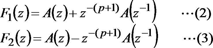
0<θ[1]<θ[2]<…<θ[p]<π
を満たす。
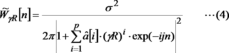

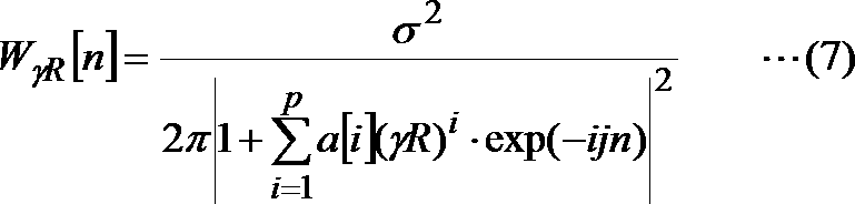
^a[1]×(γR),^a[2]×(γR)2,…,^a[p]×(γR)p
を用いる。
~a[1]×(γR),~a[2]×(γR)2,…,~a[p]×(γR)p
を用いる。
aγR[i]=a[i]×(γR)i(i=1,…,p)
であるとして、補正済量子化済線形予測係数列^a[1]×(γR),^a[2]×(γR)2,…,^a[p]×(γR)pは補正済線形予測係数列aγR[1],aγR[2],…,aγR[p]を高精度で近似する系列であることが望ましい。
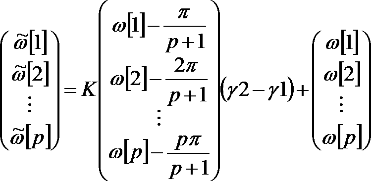
第一実施形態の符号化装置は、時間領域での符号化を行うフレームでは線形予測係数から変換されたLSPパラメータを符号化してLSP符号を得て、周波数領域での符号化を行うフレームでは補正された線形予測係数から変換された補正済LSPパラメータを符号化して補正済LSP符号を得て、周波数領域での符号化を行ったフレームの次のフレームで時間領域での符号化を行うときには、補正済LSP符号に対応するLSPパラメータに対応する線形予測係数を逆補正して得られる線形予測係数をLSPに変換したものを次のフレームの時間領域での符号化で用いるLSPパラメータとするものである。
符号化装置1は、図4に示すように、従来の符号化装置9と同様に、入力部100、線形予測分析部105、LSP生成部110、LSP符号化部115、特徴量抽出部120、周波数領域符号化部150、遅延入力部165、時間領域符号化部170及び出力部175を例えば含み、さらに、線形予測係数補正部125、補正済LSP生成部130、補正済LSP符号化部135、量子化済線形予測係数生成部140、第1量子化済平滑化済パワースペクトル包絡系列計算部145、量子化済線形予測係数逆補正部155、逆補正済LSP生成部160を例えば含む。
図5を参照して、第一実施形態の符号化方法を説明する。以下では、上述の従来技術との相違点を中心に説明する。
0<θγR[1]<θγR[2]<…<θγR[p]<π
を満たす。
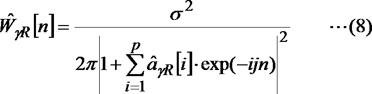
0<^θ’[1]<^θ’[2]<…<^θ’[p]<π
を満たす系列である。
復号装置2は、図6に示すように、入力部200、識別符号復号部205、LSP符号復号部210、補正済LSP符号復号部215、復号線形予測係数生成部220、第1復号平滑化済パワースペクトル包絡系列計算部225、周波数領域復号部230、復号線形予測係数逆補正部235、復号逆補正済LSP生成部240、遅延入力部245、時間領域復号部250及び出力部255を例えば含む。
図7を参照して、第一実施形態の復号方法を説明する。
^a[1]×(γR),^a[2]×(γR)2,…,^a[p]×(γR)p
を用いる。
~a[1]×(γR),~a[2]×(γR)2,…,~a[p]×(γR)p
を用いる。つまり、
~θ[i]=0.5×^θ[f-1][i]+0.5×^θ[i](i=1,…,p)
である。
符号化装置1の補正済LSP符号化部135では、補正済LSPパラメータ列θγR[1],θγR[2],…,θγR[p]と補正済量子化済LSPパラメータ列^θγR[1],^θγR[2],…,^θγR[p]との量子化歪を最小化するような補正済量子化済LSPパラメータ列^θγR[1],^θγR[2],…,^θγR[p]を求める。これにより、聴感覚を考慮した(すなわち、補正係数γRで平滑化した)パワースペクトル包絡系列を高精度で近似するように補正済量子化済LSPパラメータ列^θγR[1],^θγR[2],…,^θγR[p]を決定することができる。補正済量子化済LSPパラメータ列^θγR[1],^θγR[2],…,^θγR[p]を周波数領域に展開して得られるパワースペクトル包絡系列である量子化済平滑化済パワースペクトル包絡系列^WγR[1],^WγR[2],…,^WγR[N]は、平滑化済パワースペクトル包絡系列WγR[1],WγR[2],…,WγR[N]を高精度で近似することができる。LSP符号C1と補正済LSP符号Cγの符号量が同じであれば、第一実施形態の方が従来よりも周波数領域の符号化の符号化歪を小さくできる。また、従来の符号化方法と同じ符号化歪を仮定した場合は、LSP符号C1よりも補正済LSP符号Cγの方が従来よりも符号量が小さくなる。したがって、従来と同じ符号化歪であれば従来よりも符号量を小さくし、従来と同じ符号量であれば従来よりも符号化歪を小さくすることができる。
第一実施形態の符号化装置1及び復号装置2では、特に逆補正済LSP生成部160、復号逆補正済LSP生成部240の計算コストが大きい。そこで、第二実施形態の符号化装置3では、線形予測係数を経由することなく、補正済量子化済LSPパラメータ列^θγR[1],^θγR[2],…,^θγR[p]から量子化済LSPパラメータ列^θ[1],^θ[2],…,^θ[p]の各値の近似値の系列である近似量子化済LSPパラメータ列^θ[1]app,^θ[2]app,…,^θ[p]appを直接生成する。同様に、第二実施形態の復号装置4では、線形予測係数を経由することなく、復号補正済LSPパラメータ列^θγR[1],^θγR[2],…,^θγR[p]から復号LSPパラメータ列^θ[1],^θ[2],…,^θ[p]の各値の近似値の系列である復号近似LSPパラメータ列^θ[1]app,^θ[2]app,…,^θ[p]appを直接生成する。
図8に、第二実施形態の符号化装置3の機能構成を示す。
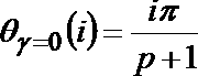
0<θγ[1]<θγ[2]…<θγ[p]<π
の性質を満たす。

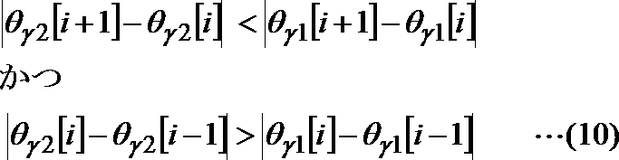



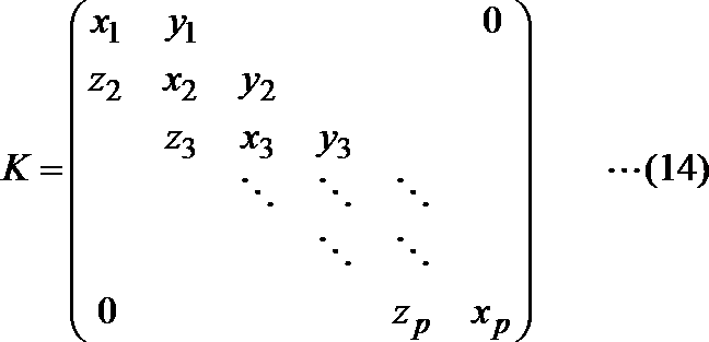

~Θγ2=(~θγ2[1],~θγ2[2],…,~θγ2[p])T
はΘγ2の近似値である。




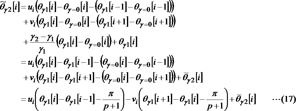

図12を参照して、第二実施形態の符号化方法を説明する。以下では、上述の実施形態との相違点を中心に説明する。

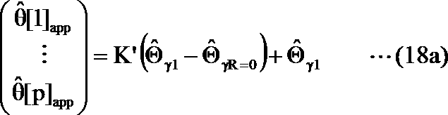
<復号装置>
図13に、第二実施形態の復号装置4の機能構成を示す。
図14を参照して、第二実施形態の復号方法を説明する。以下では、上述の実施形態との相違点を中心に説明する。
LSP線形変換部300及び復号LSP線形変換部400で用いる変換行列Kは、以下のような方法により予め求めておき、符号化装置3及び復号装置4内の記憶部(図示せず)に格納しておく。
ここで、
^Θ(m) γ1=(^θγ=1 (m)[1],…,^θγ=1 (m)[p])T
とする。
aγ (m)[i]=a(m)[i]×(γL)i
を計算する。
ここで、
^Θ(m) γ2=(^θγL (m)[1],…,^θγL (m)[p])T
とする。
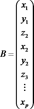
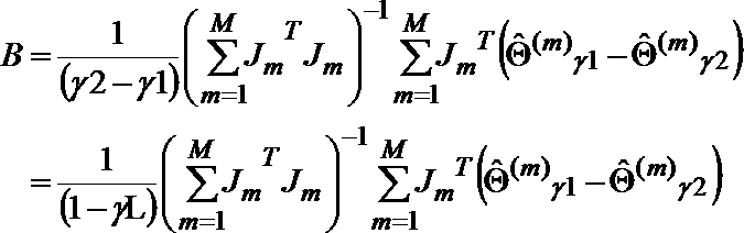
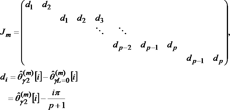
xx1 =1.11499, yy1 =-0.54272,
zz2 =-0.83414f,xx2 =1.59810f,yy2 =-0.70966,
zz3 =-0.49432, xx3 =1.38370, yy3 =-0.78076,
zz4 =-0.39319, xx4 =1.23032, yy4 =-0.67921,
zz5 =-0.39166, xx5 =1.18521, yy5 =-0.69088,
zz6 =-0.34784, xx6 =1.04839, yy6 =-0.60619,
zz7 =-0.41279, xx7 =1.13305, yy7 =-0.63247,
zz8 =-0.36450, xx8 =0.95694, yy8 =-0.53039,
zz9 =-0.43984, xx9 =1.01910, yy9 =-0.51707,
zz10=-0.40120, xx10=0.90395, yy10=-0.44594,
zz11=-0.49262, xx11=1.07345, yy11=-0.51892,
zz12=-0.41695, xx12=0.96596, yy12=-0.49247,
zz13=-0.45002, xx13=1.00336, yy13=-0.48790,
zz14=-0.46854, xx14=0.93258, yy14=-0.41927,
zz15=-0.45020, xx15=0.88783
xx1 =-0.557012055,yy1 =0.213853042,
zz2 =0.110112745,xx2 =-0.534830085,yy2 =0.2440903,
zz3 =0.149879603,xx3 =-0.522734808,yy3 =0.23494022,
zz4 =0.144479327,xx4 =-0.533013231,yy4 =0.259021145,
zz5 =0.136523255,xx5 =-0.502606738,yy5 =0.248139539,
zz6 =0.138005088,xx6 =-0.478327709,yy6 =0.244219107,
zz7 =0.133771751,xx7 =-0.467186849,yy7 =0.243988642,
zz8 =0.13667916, xx8 =-0.408737408,yy8 =0.192803054,
zz9 =0.160602461,xx9 =-0.427436157,yy9 =0.190554547,
zz10=0.147621742,xx10=-0.383087812,yy10=0.165954888,
zz11=0.18358465, xx11=-0.434034351,yy11=0.183004742,
zz12=0.166249458,xx12=-0.409482196,yy12=0.170107295,
zz13=0.162343147,xx13=-0.409804718,yy13=0.165221097,
zz14=0.178158258,xx14=-0.400869431,yy14=0.123020055,
zz15=0.171958144,xx15=-0.447472325
^Θ(m) γ1=(^θγL (m)[1],…,^θγL (m)[p])T
とし、(ステップ4)では^Θ(m) γ2を
^Θ(m) γ2=(^θγ=1 (m)[1],…,^θγ=1 (m)[p])T
とし、(ステップ5)では学習用データQに含まれる各LSPパラメータ列の組(^Θ(m) γ1,^Θ(m) γ2)について、γ1=1,γ2=γL,^Θγ1=^Θ(m) γ1,^Θγ2=^Θ(m) γ2として、式(13b)のモデルに代入し、自乗誤差基準で行列Kの係数を学習した場合に相当する。
第二実施形態の符号化装置3は、第一実施形態と同様に、従来の符号化装置9における量子化済線形予測係数生成部900、量子化済線形予測係数補正部905及び近似平滑化済パワースペクトル包絡系列計算部910を、線形予測係数補正部125、補正済LSP生成部130、補正済LSP符号化部135、量子化済線形予測係数生成部140及び第1量子化済平滑化済パワースペクトル包絡系列計算部145に置き換えた構成であるため、第一実施形態の符号化装置1と同様の効果を有する。すなわち、従来と同じ符号化歪であれば従来よりも符号量を小さくし、従来と同じ符号量であれば従来よりも符号化歪を小さくすることができる。
第二実施形態の符号化装置3では、フレーム毎に、時間領域での符号化を行うか周波数領域での符号化を行うかを、入力音響信号の時間変動の大きさに基づいて決定している。入力音響信号の時間変動が大きく、時間領域での符号化が選択されたフレームでも、実際には時間領域での符号化によって再構成される音響信号のほうが周波数領域での符号化によって再構成される信号よりも入力音響信号との歪を小さくできる場合も有り得る。また、入力音響信号の時間変動が小さく、時間領域での符号化が選択されたフレームでも、実際には周波数領域での符号化によって再構成される音響信号のほうが時間領域での符号化によって再構成される音響信号よりも入力音響信号との歪を小さくできる場合も有り得る。すなわち、第二実施形態の符号化装置3では、時間領域での符号化と周波数領域での符号化のうちの、入力音響信号との歪が小さくできる符号化方法を必ず選択できているわけではない。そこで、第二実施形態の変形例の符号化装置8では、フレーム毎に、時間領域での符号化と周波数領域での符号化の両方を行って、入力音響信号との歪を小さくできるほうを選択する。
図15に、第二実施形態の変形例の符号化装置8の機能構成を示す。
図16を参照して、第二実施形態の変形例の符号化方法を説明する。以下では、第二実施形態との相違点を中心に説明する。
第二実施形態の変形例の符号化装置8が出力した符号列は、第二実施形態の符号化装置3が出力した符号列と同様に、第二実施形態の復号装置4で復号できる。
第二実施形態の変形例の符号化装置8は、第二実施形態の符号化装置3と同様の効果を奏するものであり、さらに、第二実施形態の符号化装置3よりも出力する符号量を小さくする効果を奏するものである。
第一実施形態の符号化装置1及び第二実施形態の符号化装置3では、補正済量子化済LSPパラメータ列^θγR[1],^θγR[2],…,^θγR[p]を線形予測係数に一旦変換してから、量子化済平滑化済パワースペクトル包絡系列^WγR[1],^WγR[2],…,^WγR[N]を計算していた。第三実施形態の符号化装置5では、補正済量子化済LSPパラメータ列を線形予測係数に変換することなく、補正済量子化済LSPパラメータ列^θγR[1],^θγR[2],…,^θγR[p]から量子化済平滑化済パワースペクトル包絡系列^WγR[1],^WγR[2],…,^WγR[N]を直接計算する。同様に、第三実施形態の復号装置6では、復号補正済LSPパラメータ列を線形予測係数に変換することなく、復号補正済LSPパラメータ列^θγR[1],^θγR[2],…,^θγR[p]から復号平滑化済パワースペクトル包絡系列^WγR[1],^WγR[2],…,^WγR[N]を直接計算する。
図17に、第三実施形態の符号化装置5の機能構成を示す。
図18を参照して、第三実施形態の符号化方法を説明する。以下では、上述の実施形態との相違点を中心に説明する。

図19に、第三実施形態の復号装置6の機能構成を示す。
図20を参照して、第三実施形態の復号方法を説明する。以下では、上述の実施形態との相違点を中心に説明する。
量子化済LSPパラメータ列^θ[1],^θ[2],…,^θ[p]は、
0<^θ[1]<…<^θ[p]<π
を満たす系列である。つまり、昇順に並んだ系列である。一方、LSP線形変換部300で生成される近似量子化済LSPパラメータ列^θ[1]app,^θ[2]app,…,^θ[p]appは近似的な変換により生成したものであるため、昇順にならないことがある。そこで、第四実施形態ではLSP線形変換部300から出力される近似量子化済LSPパラメータ列^θ[1]app,^θ[2]app,…,^θ[p]appを昇順に並べ替える処理を追加する。
図21に、第四実施形態の符号化装置7の機能構成を示す。
符号化装置7は、第二実施形態の符号化装置5と比較して、近似LSP系列修正部700をさらに含む点が異なる。
図22を参照して、第四実施形態の符号化方法を説明する。以下では、上述の実施形態との相違点を中心に説明する。
上述の実施形態ではLSPパラメータを前提として説明したが、LSPパラメータ列の代わりに、ISPパラメータ列を用いてもよい。ISPパラメータ列ISP[1],…,ISP[p]は、p-1次のLSPパラメータ列とp次(最高次)のPARCOR係数kpからなる系列と等価である。つまり、
ISP[i]=θ[i] for i=1,…,p-1
ISP[p]=kp
である。
^ISPγR[1]=^θγR[i]
^ISPγR[p]=^kp
である。^kpはkpの量子化値である。
(ステップ1)^Θγ1=(^ISPγR[1],…,^ISPγR[p-1])Tとし、pをp-1に置き換えて、式(18)を計算して、^θ[1]app,…,^θ[p-1]appを求める。
ここで、
^ISP[i]app=^θ[i]app(i=1,…,p-1)
とする。
(ステップ2)以下の式で定義される^ISP[p]appを求める。
^ISP[p]app=^ISPγR[p]・(1/γR)p
[第五実施形態]
符号化装置3、5、7、8が備えるLSP線形変換部300、復号装置4、6が備える復号LSP線形変換部400を、独立した周波数領域パラメータ列生成装置として構成することも可能である。
第五実施形態の周波数領域パラメータ列生成装置10は、図23に示すように、パラメータ列変換部20を例えば含み、周波数領域パラメータω[1],ω[2],…,ω[p]を入力とし、変換後周波数領域パラメータ~ω[1],~ω[2],…,~ω[p]を出力する。

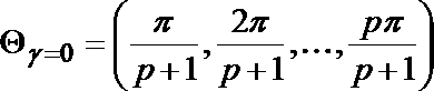
a[1]×(γ1),a[2]×(γ1)2,…,a[p]×(γ1)p
と等価な周波数領域のパラメータ列、もしくは、その量子化値である。また、変換後周波数領域パラメータ~ω[1],~ω[2],…,~ω[p]は、線形予測係数a[1],a[2],…,a[p]の各係数a[i]に係数γ2のi乗を乗じることにより補正した係数列である
a[1]×(γ2),a[2]×(γ2)2,…,a[p]×(γ2)p
と等価な周波数領域のパラメータ列を近似する系列となる。
第五実施形態の周波数領域パラメータ列生成装置は、符号化装置3、5、7、8や復号装置4、6と同様に、符号化装置1や復号装置2のような周波数領域パラメータから線形予測係数を介して変換後周波数領域パラメータを求める場合よりも少ない演算量で、周波数領域パラメータから変換後周波数領域パラメータを求めることができる。
上記実施形態で説明した各装置における各種の処理機能をコンピュータによって実現する場合、各装置が有すべき機能の処理内容はプログラムによって記述される。そして、このプログラムをコンピュータで実行することにより、上記各装置における各種の処理機能がコンピュータ上で実現される。
Claims (27)
- pを1以上の整数とし、a[1],a[2],…,a[p]を所定の時間区間の音信号を線形予測分析して得られる線形予測係数列とし、ω[1],ω[2],…,ω[p]を上記線形予測係数列a[1],a[2],…,a[p]に由来する周波数領域パラメータ列とし、
上記周波数領域パラメータ列ω[1],ω[2],…,ω[p]を入力として、変換後周波数領域パラメータ列~ω[1],~ω[2],…,~ω[p]を求めるパラメータ列変換ステップを含み、
上記パラメータ列変換ステップは、
上記変換後周波数領域パラメータ列~ω[1],~ω[2],…,~ω[p]における各~ω[i](i=1,2,…,p)を、
ω[i]とω[i]に近接する1つまたは複数の周波数領域パラメータとの値の関係に基づく線形変換により変換後周波数領域パラメータ~ω[i]の値を求める
周波数領域パラメータ列生成方法。 - 請求項1に記載の周波数領域パラメータ列生成方法であって、
上記線形変換は、
上記周波数領域パラメータ列ω[1],ω[2],…,ω[p]よりも、上記変換後周波数領域パラメータ列のほうが、パラメータ値の間隔が均等間隔に近くなるような、または、均等間隔から遠くなるような、
線形変換である
周波数領域パラメータ列生成方法。 - pを1以上の整数とし、a[1],a[2],…,a[p]を所定の時間区間の音信号を線形予測分析して得られる線形予測係数列とし、
ω[1],ω[2]…,ω[p]を、
上記線形予測係数列a[1],a[2],…,a[p]に由来するLSPパラメータ列、
上記線形予測係数列a[1],a[2],…,a[p]に由来するISPパラメータ列、
上記線形予測係数列a[1],a[2],…,a[p]に由来するLSFパラメータ列、
上記線形予測係数列a[1],a[2],…,a[p]に由来するISFパラメータ列、
上記線形予測係数列a[1],a[2],…,a[p]に由来し、かつ、ω[1],ω[2]…,ω[p-1]の全てが0からπまでの間に存在し、かつ、線形予測係数列に含まれる全ての線形予測係数が0である場合にはω[1],ω[2]…,ω[p-1]が0からπまでの間に均等間隔に存在する周波数領域パラメータ列、のいずれかとし、
γ1及びγ2をそれぞれ1以下の正の定数である補正係数とし、Kを予め定められたp×pの帯行列とし、
次式により定義される変換後周波数領域パラメータ列~ω[1],~ω[2],…,~ω[p]を生成するパラメータ列変換ステップを含む
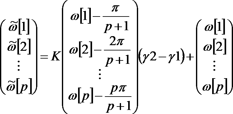
周波数領域パラメータ列生成方法。 - 請求項3に記載の周波数領域パラメータ列生成方法であって、
上記帯行列Kは、対角要素が0以上の値であり、行方向において対角要素に隣接する要素が0以下の値である
周波数領域パラメータ列生成方法。 - pを1以上の整数とし、a[1],a[2],…,a[p]を所定の時間区間の音信号を線形予測分析して得られる線形予測係数列とし、ω[1],ω[2],…,ω[p]を上記線形予測係数列a[1],a[2],…,a[p]に由来する周波数領域パラメータ列とし、
上記周波数領域パラメータ列ω[1],ω[2],…,ω[p]を入力として、変換後周波数領域パラメータ列~ω[1],~ω[2],…,~ω[p]を求めるパラメータ列変換ステップを含み、
上記パラメータ列変換ステップは、
上記変換後周波数領域パラメータ列~ω[1],~ω[2],…,~ω[p]における各~ω[i](i=1,2,…,p)を、
ω[i]がω[i+1]とω[i-1]との中点よりもω[i+1]に近い場合には、~ω[i]が~ω[i+1]と~ω[i-1]との中点よりも~ω[i+1]に近く、かつ、ω[i+1]-ω[i]よりも~ω[i+1]-~ω[i]の方が値が小さくなるように求め、
ω[i]がω[i+1]とω[i-1]との中点よりもω[i-1]に近い場合には、~ω[i]が~ω[i+1]と~ω[i-1]との中点よりも~ω[i-1]に近く、かつ、ω[i]-ω[i-1]よりも~ω[i]-~ω[i-1]の方が値が小さくなるように求める
周波数領域パラメータ列生成方法。 - pを1以上の整数とし、a[1],a[2],…,a[p]を所定の時間区間の音信号を線形予測分析して得られる線形予測係数列とし、ω[1],ω[2],…,ω[p]を上記線形予測係数列a[1],a[2],…,a[p]に由来する周波数領域パラメータ列とし、
上記周波数領域パラメータ列ω[1],ω[2],…,ω[p]を入力として、変換後周波数領域パラメータ列~ω[1],~ω[2],…,~ω[p]を求めるパラメータ列変換ステップを含み、
上記パラメータ列変換ステップは、
上記変換後周波数領域パラメータ列~ω[1],~ω[2],…,~ω[p]における各~ω[i](i=1,2,…,p)を、
ω[i]がω[i+1]とω[i-1]との中点よりもω[i+1]に近い場合には、~ω[i]が~ω[i+1]と~ω[i-1]との中点よりも~ω[i+1]に近く、かつ、ω[i+1]-ω[i]よりも~ω[i+1]-~ω[i]の方が値が大きくなるように求め、
ω[i]がω[i+1]とω[i-1]との中点よりもω[i-1]に近い場合には、~ω[i]が~ω[i+1]と~ω[i-1]との中点よりも~ω[i-1]に近く、かつ、ω[i]-ω[i-1]よりも~ω[i]-~ω[i-1]の方が値が大きくなるように求める
周波数領域パラメータ列生成方法。 - 請求項1から6のいずれかに記載の周波数領域パラメータ列生成方法であって、
γ1を1以下の正の定数とし、
上記周波数領域パラメータ列ω[1],ω[2],…,ω[p]における各ω[i](i=1,2,…,p)は、aγ1[i]=a[i]×(γ1)iとして、aγ1[1],aγ1[2],…,aγ1[p]と等価な周波数領域のパラメータまたはその量子化値である
周波数領域パラメータ列生成方法。 - 請求項1から7のいずれかに記載の周波数領域パラメータ列生成方法の各ステップを含む符号化方法であって、
γを1以下の正の定数である補正係数とし、
上記線形予測係数列a[1],a[2],…,a[p]を上記補正係数γを用いて補正した補正済線形予測係数列aγ[1],aγ[2],…,aγ[p]を生成する線形予測係数補正ステップと、
上記補正済線形予測係数列aγ[1],aγ[2],…,aγ[p]を用いて補正済LSPパラメータ列θγ[1],θγ[2],…,θγ[p]を生成する補正済LSP生成ステップと、
上記補正済LSPパラメータ列θγ[1],θγ[2],…,θγ[p]を符号化して、補正済LSP符号及び上記補正済LSP符号に対応する補正済量子化済LSPパラメータ列^θγ[1],^θγ[2],…,^θγ[p]を生成する補正済LSP符号化ステップと、
上記周波数領域パラメータ列ω[1],ω[2],…,ω[p]を上記補正済量子化済LSPパラメータ列^θγ[1],^θγ[2],…,^θγ[p]とし、γ1=γとし、γ2=1とし、上記パラメータ列変換ステップを実行することにより、上記変換後周波数領域パラメータ列~ω[1],~ω[2],…,~ω[p]を近似量子化済LSPパラメータ列^θapp[1],^θapp[2],…,^θapp[p]として生成するLSP線形変換ステップと、
上記補正済量子化済LSPパラメータ列^θγ[1],^θγ[2],…,^θγ[p]を線形予測係数に変換した補正済量子化済線形予測係数列^aγ[1],^aγ[2],…,^aγ[p]を生成する量子化済線形予測係数列生成ステップと、
上記補正済量子化済線形予測係数列^aγ[1],^aγ[2],…,^aγ[p]に対応する周波数領域の系列である量子化済平滑化済パワースペクトル包絡系列^Wγ[1],^Wγ[2],…,^Wγ[N]を計算する量子化済平滑化済パワースペクトル包絡系列計算ステップと、
上記音信号に対応する周波数領域サンプル列X[1],X[2],…,X[N]を、上記量子化済平滑化済パワースペクトル包絡系列^Wγ[1],^Wγ[2],…,^Wγ[N]を用いて符号化した周波数領域信号符号を生成する周波数領域符号化ステップと、
上記線形予測係数列a[1],a[2],…,a[p]を用いてLSPパラメータ列θ[1],θ[2],…,θ[p]を生成するLSP生成ステップと、
上記LSPパラメータ列θ[1],θ[2],…,θ[p]を符号化して、LSP符号及び上記LSP符号に対応する量子化済LSPパラメータ列^θ[1],^θ[2],…,^θ[p]を生成するLSP符号化ステップと、
上記音信号を、前の時間区間の上記LSP符号化ステップで得た量子化済LSPパラメータ列と、前の時間区間のLSP線形変換ステップで得た近似量子化済LSPパラメータ列のいずれかと、上記所定の時間区間の量子化済LSPパラメータ列とを用いて、符号化して時間領域信号符号を生成する時間領域符号化ステップと、
を含む符号化方法。 - 請求項1から7のいずれかに記載の周波数領域パラメータ列生成方法の各ステップを含む符号化方法であって、
γを1以下の正の定数である補正係数とし、
上記線形予測係数列a[1],a[2],…,a[p]を上記補正係数γを用いて補正した補正済線形予測係数列aγ[1],aγ[2],…,aγ[p]を生成する線形予測係数補正ステップと、
上記補正済線形予測係数列aγ[1],aγ[2],…,aγ[p]を用いて補正済LSPパラメータ列θγ[1],θγ[2],…,θγ[p]を生成する補正済LSP生成ステップと、
上記補正済LSPパラメータ列θγ[1],θγ[2],…,θγ[p]を符号化して、補正済LSP符号及び上記補正済LSP符号に対応する補正済量子化済LSPパラメータ列^θγ[1],^θγ[2],…,^θγ[p]を生成する補正済LSP符号化ステップと、
上記周波数領域パラメータ列ω[1],ω[2],…,ω[p]を上記補正済量子化済LSPパラメータ列^θγ[1],^θγ[2],…,^θγ[p]とし、γ1=γとし、γ2=1とし、上記パラメータ列変換ステップを実行することにより、上記変換後周波数領域パラメータ列~ω[1],~ω[2],…,~ω[p]を近似量子化済LSPパラメータ列^θapp[1],^θapp[2],…,^θapp[p]として生成するLSP線形変換ステップと、
上記補正済量子化済LSPパラメータ列^θγ[1],^θγ[2],…,^θγ[p]に基づいて量子化済平滑化済パワースペクトル包絡系列^Wγ[1],^Wγ[2],…,^Wγ[N]を計算する量子化済平滑化済パワースペクトル包絡系列計算ステップと、
上記音信号に対応する周波数領域サンプル列X[1],X[2],…,X[N]を、上記量子化済平滑化済パワースペクトル包絡系列^Wγ[1],^Wγ[2],…,^Wγ[N]を用いて符号化した周波数領域信号符号を生成する周波数領域符号化ステップと、
上記線形予測係数列a[1],a[2],…,a[p]を用いてLSPパラメータ列θ[1],θ[2],…,θ[p]を生成するLSP生成ステップと、
上記LSPパラメータ列θ[1],θ[2],…,θ[p]を符号化して、LSP符号及び上記LSP符号に対応する量子化済LSPパラメータ列^θ[1],^θ[2],…,^θ[p]を生成するLSP符号化ステップと、
上記音信号を、前の時間区間の上記LSP符号化ステップで得た量子化済LSPパラメータ列と、前の時間区間のLSP線形変換ステップで得た近似量子化済LSPパラメータ列のいずれかと、上記所定の時間区間の量子化済LSPパラメータ列とを用いて、符号化して時間領域信号符号を生成する時間領域符号化ステップと、
を含む符号化方法。 - 請求項8または9に記載の符号化方法であって、
上記周波数領域符号化ステップで生成した周波数領域信号符号と、上記時間領域符号化ステップで生成した時間領域信号符号と、のいずれかを出力する出力ステップ
を更に有し、
上記時間領域符号化ステップは、
前の時間区間の出力ステップにおいて周波数領域信号符号が出力された場合には、前の時間区間のLSP線形変換ステップで得た近似量子化済LSPパラメータ列を用いた符号化を行い、
前の時間区間の出力ステップにおいて時間領域信号符号が出力された場合には、前の時間区間のLSP生成ステップで得た量子化済LSPパラメータ列を用いた符号化を行う
符号化方法。 - 請求項1から7のいずれかに記載の周波数領域パラメータ列生成方法の各ステップを含む復号方法であって、
入力された補正済LSP符号を復号して復号補正済LSPパラメータ列^θγ[1],^θγ[2],…,^θγ[p]を得る補正済LSP符号復号ステップと、
上記周波数領域パラメータ列ω[1],ω[2],…,ω[p]を上記復号補正済LSPパラメータ列^θγ[1],^θγ[2],…,^θγ[p]とし、γ1=γとし、γ2=1とし、上記パラメータ列変換ステップを実行することにより、上記変換後周波数領域パラメータ列~ω[1],~ω[2],…,~ω[p]を復号近似LSPパラメータ列^θapp[1],^θapp[2],…,^θapp[p]として生成する復号LSP線形変換ステップと、
上記復号補正済LSPパラメータ列^θγ[1],^θγ[2],…,^θγ[p]を線形予測係数に変換した復号補正済線形予測係数列^aγ[1],^aγ[2],…,^aγ[p]を生成する復号線形予測係数列生成ステップと、
上記復号補正済線形予測係数列^aγ[1],^aγ[2],…,^aγ[p]に対応する周波数領域の系列である復号平滑化済パワースペクトル包絡系列^Wγ[1],^Wγ[2],…,^Wγ[N]を計算する復号平滑化済パワースペクトル包絡系列計算ステップと、
入力された周波数領域信号符号を復号して得られた周波数領域信号列と、上記復号平滑化済パワースペクトル包絡系列^Wγ[1],^Wγ[2],…,^Wγ[N]とを用いて復号音響信号を生成する周波数領域復号ステップと、
入力されたLSP符号を復号して復号LSPパラメータ列^θ[1],^θ[2],…,^θ[p]を得るLSP符号復号ステップと、
入力された時間領域信号符号を復号し、前の時間区間の上記LSP符号復号ステップで得た復号LSPパラメータ列と、前の時間区間の上記LSP線形変換ステップで得た復号近似LSPパラメータ列のいずれかと、上記所定の時間区間の復号LSPパラメータ列とを用いて合成して、復号音響信号を生成する時間領域復号ステップと、
を含む復号方法。 - 請求項1から7のいずれかに記載の周波数領域パラメータ列生成方法の各ステップを含む復号方法であって、
入力された補正済LSP符号を復号して復号補正済LSPパラメータ列^θγ[1],^θγ[2],…,^θγ[p]を得る補正済LSP符号復号ステップと、
上記周波数領域パラメータ列ω[1],ω[2],…,ω[p]を上記復号補正済LSPパラメータ列^θγ[1],^θγ[2],…,^θγ[p]とし、γ1=γとし、γ2=1とし、上記パラメータ列変換ステップを実行することにより、上記変換後周波数領域パラメータ列~ω[1],~ω[2],…,~ω[p]を復号近似LSPパラメータ列^θapp[1],^θapp[2],…,^θapp[p]として生成する復号LSP線形変換ステップと、
上記復号補正済LSPパラメータ列^θγ[1],^θγ[2],…,^θγ[p]に基づいて復号平滑化済パワースペクトル包絡系列^Wγ[1],^Wγ[2],…,^Wγ[N]を計算する復号平滑化済パワースペクトル包絡系列計算ステップと、
入力された周波数領域信号符号を復号して得られた周波数領域信号列と、上記復号平滑化済パワースペクトル包絡系列^Wγ[1],^Wγ[2],…,^Wγ[N]とを用いて復号音響信号を生成する周波数領域復号ステップと、
入力された周波数領域信号符号を復号して得られた周波数領域信号列と、上記復号平滑化済パワースペクトル包絡系列^Wγ[1],^Wγ[2],…,^Wγ[N]とを用いて復号音響信号を生成する周波数領域復号ステップと、
入力されたLSP符号を復号して復号LSPパラメータ列^θ[1],^θ[2],…,^θ[p]を得るLSP符号復号ステップと、
入力された時間領域信号符号を復号し、前の時間区間の上記LSP符号復号ステップで得た復号LSPパラメータ列と、前の時間区間の上記LSP線形変換ステップで得た復号近似LSPパラメータ列のいずれかと、上記所定の時間区間の復号LSPパラメータ列とを用いて合成して、復号音響信号を生成する時間領域復号ステップと、
を含む復号方法。 - pを1以上の整数とし、a[1],a[2],…,a[p]を所定の時間区間の音信号を線形予測分析して得られる線形予測係数列とし、ω[1],ω[2],…,ω[p]を上記線形予測係数列a[1],a[2],…,a[p]に由来する周波数領域パラメータ列とし、
上記周波数領域パラメータ列ω[1],ω[2],…,ω[p]を入力として、変換後周波数領域パラメータ列~ω[1],~ω[2],…,~ω[p]を求めるパラメータ列変換部を含み、
上記パラメータ列変換部は、
上記変換後周波数領域パラメータ列~ω[1],~ω[2],…,~ω[p]における各~ω[i](i=1,2,…,p)を、
ω[i]とω[i]に近接する1つまたは複数の周波数領域パラメータとの値の関係に基づく線形変換により変換後周波数領域パラメータ~ω[i]の値を求める
周波数領域パラメータ列生成装置。 - pを1以上の整数とし、a[1],a[2],…,a[p]を所定の時間区間の音信号を線形予測分析して得られる線形予測係数列とし、
ω[1],ω[2]…,ω[p]を、
上記線形予測係数列a[1],a[2],…,a[p]に由来するLSPパラメータ列、
上記線形予測係数列a[1],a[2],…,a[p]に由来するISPパラメータ列、
上記線形予測係数列a[1],a[2],…,a[p]に由来するLSFパラメータ列、
上記線形予測係数列a[1],a[2],…,a[p]に由来するISFパラメータ列、
上記線形予測係数列a[1],a[2],…,a[p]に由来し、かつ、ω[1],ω[2]…,ω[p-1]の全てが0からπまでの間に存在し、かつ、線形予測係数列に含まれる全ての線形予測係数が0である場合にはω[1],ω[2]…,ω[p-1]が0からπまでの間に均等間隔に存在する周波数領域パラメータ列、のいずれかとし、
γ1及びγ2をそれぞれ1以下の正の定数である補正係数とし、Kを予め定められたp×pの帯行列とし、
次式により定義される変換後周波数領域パラメータ列~ω[1],~ω[2],…,~ω[p]を生成するパラメータ列変換部を含む
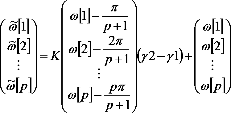
周波数領域パラメータ列生成装置。 - 請求項14に記載の周波数領域パラメータ列生成装置であって、
上記帯行列Kは、対角要素が0以上の値であり、行方向において対角要素に隣接する要素が0以下の値である
周波数領域パラメータ列生成装置。 - pを1以上の整数とし、a[1],a[2],…,a[p]を所定の時間区間の音信号を線形予測分析して得られる線形予測係数列とし、ω[1],ω[2],…,ω[p]を上記線形予測係数列a[1],a[2],…,a[p]に由来する周波数領域パラメータ列とし、
上記周波数領域パラメータ列ω[1],ω[2],…,ω[p]を入力として、変換後周波数領域パラメータ列~ω[1],~ω[2],…,~ω[p]を求めるパラメータ列変換部を含み、
上記パラメータ列変換部は、
上記変換後周波数領域パラメータ列~ω[1],~ω[2],…,~ω[p]における各~ω[i](i=1,2,…,p)を、
ω[i]がω[i+1]とω[i-1]との中点よりもω[i+1]に近い場合には、~ω[i]が~ω[i+1]と~ω[i-1]との中点よりも~ω[i+1]に近く、かつ、ω[i+1]-ω[i]よりも~ω[i+1]-~ω[i]の方が値が小さくなるように求め、
ω[i]がω[i+1]とω[i-1]との中点よりもω[i-1]に近い場合には、~ω[i]が~ω[i+1]と~ω[i-1]との中点よりも~ω[i-1]に近く、かつ、ω[i]-ω[i-1]よりも~ω[i]-~ω[i-1]の方が値が小さくなるように求める
周波数領域パラメータ列生成装置。 - pを1以上の整数とし、a[1],a[2],…,a[p]を所定の時間区間の音信号を線形予測分析して得られる線形予測係数列とし、ω[1],ω[2],…,ω[p]を上記線形予測係数列a[1],a[2],…,a[p]に由来する周波数領域パラメータ列とし、
上記周波数領域パラメータ列ω[1],ω[2],…,ω[p]を入力として、変換後周波数領域パラメータ列~ω[1],~ω[2],…,~ω[p]を求めるパラメータ列変換部を含み、
上記パラメータ列変換部は、
上記変換後周波数領域パラメータ列~ω[1],~ω[2],…,~ω[p]における各~ω[i](i=1,2,…,p)を、
ω[i]がω[i+1]とω[i-1]との中点よりもω[i+1]に近い場合には、~ω[i]が~ω[i+1]と~ω[i-1]との中点よりも~ω[i+1]に近く、かつ、ω[i+1]-ω[i]よりも~ω[i+1]-~ω[i]の方が値が大きくなるように求め、
ω[i]がω[i+1]とω[i-1]との中点よりもω[i-1]に近い場合には、~ω[i]が~ω[i+1]と~ω[i-1]との中点よりも~ω[i-1]に近く、かつ、ω[i]-ω[i-1]よりも~ω[i]-~ω[i-1]の方が値が大きくなるように求める
周波数領域パラメータ列生成装置。 - 請求項13から17のいずれかに記載の周波数領域パラメータ列生成装置の各部を含む符号化装置であって、
γを1以下の正の定数である補正係数とし、
上記線形予測係数列a[1],a[2],…,a[p]を上記補正係数γを用いて補正した補正済線形予測係数列aγ[1],aγ[2],…,aγ[p]を生成する線形予測係数補正部と、
上記補正済線形予測係数列aγ[1],aγ[2],…,aγ[p]を用いて補正済LSPパラメータ列θγ[1],θγ[2],…,θγ[p]を生成する補正済LSP生成部と、
上記補正済LSPパラメータ列θγ[1],θγ[2],…,θγ[p]を符号化して、補正済LSP符号及び上記補正済LSP符号に対応する補正済量子化済LSPパラメータ列^θγ[1],^θγ[2],…,^θγ[p]を生成する補正済LSP符号化部と、
上記周波数領域パラメータ列ω[1],ω[2],…,ω[p]を上記補正済量子化済LSPパラメータ列^θγ[1],^θγ[2],…,^θγ[p]とし、γ1=γとし、γ2=1とし、上記パラメータ列変換部を実行することにより、上記変換後周波数領域パラメータ列~ω[1],~ω[2],…,~ω[p]を近似量子化済LSPパラメータ列^θapp[1],^θapp[2],…,^θapp[p]として生成するLSP線形変換部と、
上記補正済量子化済LSPパラメータ列^θγ[1],^θγ[2],…,^θγ[p]を線形予測係数に変換した補正済量子化済線形予測係数列^aγ[1],^aγ[2],…,^aγ[p]を生成する量子化済線形予測係数列生成部と、
上記補正済量子化済線形予測係数列^aγ[1],^aγ[2],…,^aγ[p]に対応する周波数領域の系列である量子化済平滑化済パワースペクトル包絡系列^Wγ[1],^Wγ[2],…,^Wγ[N]を計算する量子化済平滑化済パワースペクトル包絡系列計算部と、
上記音信号に対応する周波数領域サンプル列X[1],X[2],…,X[N]を、上記量子化済平滑化済パワースペクトル包絡系列^Wγ[1],^Wγ[2],…,^Wγ[N]を用いて符号化した周波数領域信号符号を生成する周波数領域符号化部と、
上記線形予測係数列a[1],a[2],…,a[p]を用いてLSPパラメータ列θ[1],θ[2],…,θ[p]を生成するLSP生成部と、
上記LSPパラメータ列θ[1],θ[2],…,θ[p]を符号化して、LSP符号及び上記LSP符号に対応する量子化済LSPパラメータ列^θ[1],^θ[2],…,^θ[p]を生成するLSP符号化部と、
上記音信号を、前の時間区間の上記LSP符号化ステップで得た量子化済LSPパラメータ列と、前の時間区間のLSP線形変換ステップで得た近似量子化済LSPパラメータ列のいずれかと、上記所定の時間区間の量子化済LSPパラメータ列とを用いて、符号化して時間領域信号符号を生成する時間領域符号化部と、
を含む符号化装置。 - 請求項13から17のいずれかに記載の周波数領域パラメータ列生成装置の各部を含む符号化装置であって、
γを1以下の正の定数である補正係数とし、
上記線形予測係数列a[1],a[2],…,a[p]を上記補正係数γを用いて補正した補正済線形予測係数列aγ[1],aγ[2],…,aγ[p]を生成する線形予測係数補正部と、
上記補正済線形予測係数列aγ[1],aγ[2],…,aγ[p]を用いて補正済LSPパラメータ列θγ[1],θγ[2],…,θγ[p]を生成する補正済LSP生成部と、
上記補正済LSPパラメータ列θγ[1],θγ[2],…,θγ[p]を符号化して、補正済LSP符号及び上記補正済LSP符号に対応する補正済LSPパラメータ列の各値を量子化した補正済量子化済LSPパラメータ列^θγ[1],^θγ[2],…,^θγ[p]を生成する補正済LSP符号化部と、
上記周波数領域パラメータ列ω[1],ω[2],…,ω[p]を上記補正済量子化済LSPパラメータ列^θγ[1],^θγ[2],…,^θγ[p]とし、γ1=γとし、γ2=1とし、上記パラメータ列変換部を実行することにより、上記変換後周波数領域パラメータ列~ω[1],~ω[2],…,~ω[p]を近似量子化済LSPパラメータ列^θapp[1],^θapp[2],…,^θapp[p]として生成するLSP線形変換部と、
上記補正済量子化済LSPパラメータ列^θγ[1],^θγ[2],…,^θγ[p]に基づいて量子化済平滑化済パワースペクトル包絡系列^Wγ[1],^Wγ[2],…,^Wγ[N]を計算する量子化済平滑化済パワースペクトル包絡系列計算部と、
上記音信号に対応する周波数領域サンプル列X[1],X[2],…,X[N]を、上記量子化済平滑化済パワースペクトル包絡系列^Wγ[1],^Wγ[2],…,^Wγ[N]を用いて符号化した周波数領域信号符号を生成する周波数領域符号化部と、
上記線形予測係数列a[1],a[2],…,a[p]を用いてLSPパラメータ列θ[1],θ[2],…,θ[p]を生成するLSP生成部と、
上記LSPパラメータ列θ[1],θ[2],…,θ[p]を符号化して、LSP符号及び上記LSP符号に対応する量子化済LSPパラメータ列^θ[1],^θ[2],…,^θ[p]を生成するLSP符号化部と、
上記音信号を、前の時間区間の上記LSP符号化ステップで得た量子化済LSPパラメータ列と、前の時間区間のLSP線形変換ステップで得た近似量子化済LSPパラメータ列のいずれかと、上記所定の時間区間の量子化済LSPパラメータ列とを用いて、符号化して時間領域信号符号を生成する時間領域符号化部と、
を含む符号化装置。 - 請求項13から17のいずれかに記載の周波数領域パラメータ列生成装置の各部を含む復号装置であって、
入力された補正済LSP符号を復号して復号補正済LSPパラメータ列^θγ[1],^θγ[2],…,^θγ[p]を得る補正済LSP符号復号部と、
上記周波数領域パラメータ列ω[1],ω[2],…,ω[p]を上記復号補正済LSPパラメータ列^θγ[1],^θγ[2],…,^θγ[p]とし、γ1=γとし、γ2=1とし、上記パラメータ列変換部を実行することにより、上記変換後周波数領域パラメータ列~ω[1],~ω[2],…,~ω[p]を復号近似LSPパラメータ列^θapp[1],^θapp[2],…,^θapp[p]として生成する復号LSP線形変換部と、
上記復号補正済LSPパラメータ列^θγ[1],^θγ[2],…,^θγ[p]を線形予測係数に変換した復号補正済線形予測係数列^aγ[1],^aγ[2],…,^aγ[p]を生成する復号線形予測係数列生成部と、
上記復号補正済線形予測係数列^aγ[1],^aγ[2],…,^aγ[p]に対応する周波数領域の系列である復号平滑化済パワースペクトル包絡系列^Wγ[1],^Wγ[2],…,^Wγ[N]を計算する復号平滑化済パワースペクトル包絡系列計算部と、
入力された周波数領域信号符号を復号して得られた周波数領域信号列と、上記復号平滑化済パワースペクトル包絡系列^Wγ[1],^Wγ[2],…,^Wγ[N]とを用いて復号音響信号を生成する周波数領域復号部と、
入力されたLSP符号を復号して復号LSPパラメータ列^θ[1],^θ[2],…,^θ[p]を得るLSP符号復号部と、
入力された時間領域信号符号を復号し、前の時間区間の上記LSP符号復号部で得た復号LSPパラメータ列と、前の時間区間の上記LSP線形変換ステップで得た復号近似LSPパラメータ列のいずれかと、上記所定の時間区間の復号LSPパラメータ列とを用いて合成して、復号音響信号を生成する時間領域復号部と、
を含む復号装置。 - 請求項13から17のいずれかに記載の周波数領域パラメータ列生成装置の各部を含む復号装置であって、
入力された補正済LSP符号を復号して復号補正済LSPパラメータ列^θγ[1],^θγ[2],…,^θγ[p]を得る補正済LSP符号復号部と、
上記周波数領域パラメータ列ω[1],ω[2],…,ω[p]を上記復号補正済LSPパラメータ列^θγ[1],^θγ[2],…,^θγ[p]とし、γ1=γとし、γ2=1とし、上記パラメータ列変換部を実行することにより、上記変換後周波数領域パラメータ列~ω[1],~ω[2],…,~ω[p]を復号近似LSPパラメータ列^θapp[1],^θapp[2],…,^θapp[p]として生成する復号LSP線形変換部と、
上記復号補正済LSPパラメータ列^θγ[1],^θγ[2],…,^θγ[p]に基づいて復号平滑化済パワースペクトル包絡系列^Wγ[1],^Wγ[2],…,^Wγ[N]を計算する復号平滑化済パワースペクトル包絡系列計算部と、
入力された周波数領域信号符号を復号して得られた周波数領域信号列と、上記復号平滑化済パワースペクトル包絡系列^Wγ[1],^Wγ[2],…,^Wγ[N]とを用いて復号音響信号を生成する周波数領域復号部と、
入力された周波数領域信号符号を復号して得られた周波数領域信号列と、上記復号平滑化済パワースペクトル包絡系列^Wγ[1],^Wγ[2],…,^Wγ[N]とを用いて復号音響信号を生成する周波数領域復号部と、
入力されたLSP符号を復号して復号LSPパラメータ列^θ[1],^θ[2],…,^θ[p]を得るLSP符号復号部と、
入力された時間領域信号符号を復号し、前の時間区間の上記LSP符号復号ステップで得た復号LSPパラメータ列と、前の時間区間の上記LSP線形変換ステップで得た復号近似LSPパラメータ列のいずれかと、上記所定の時間区間の復号LSPパラメータ列とを用いて合成して、復号音響信号を生成する時間領域復号部と、
を含む復号装置。 - 請求項1から7のいずれかに記載の周波数領域パラメータ列生成方法の各ステップをコンピュータに実行させるためのプログラム。
- 請求項8から10のいずれかに記載の符号化方法の各ステップをコンピュータに実行させるためのプログラム。
- 請求項11または12に記載の復号方法の各ステップをコンピュータに実行させるためのプログラム。
- 請求項1から7のいずれかに記載の周波数領域パラメータ列生成方法の各ステップをコンピュータに実行させるためのプログラムを記録したコンピュータ読み取り可能な記録媒体。
- 請求項8から10のいずれかに記載の符号化方法の各ステップをコンピュータに実行させるためのプログラムを記録したコンピュータ読み取り可能な記録媒体。
- 請求項11または12に記載の復号方法の各ステップをコンピュータに実行させるためのプログラムを記録したコンピュータ読み取り可能な記録媒体。
Priority Applications (17)
| Application Number | Priority Date | Filing Date | Title |
|---|---|---|---|
| EP15783646.1A EP3136387B1 (en) | 2014-04-24 | 2015-02-16 | Frequency domain parameter sequence generating method, encoding method, decoding method, frequency domain parameter sequence generating apparatus, encoding apparatus, decoding apparatus, program, and recording medium |
| ES15783646T ES2713410T3 (es) | 2014-04-24 | 2015-02-16 | Método de generación de secuencia de parámetros en el dominio de la frecuencia, método de codificación, método de descodificación, aparato de generación de secuencia de parámetros en el dominio de la frecuencia, aparato de codificación, aparato de descodificación, programa y soporte de grabación |
| PL19216781T PL3648103T3 (pl) | 2014-04-24 | 2015-02-16 | Sposób dekodowania, urządzenie dekodujące, odpowiedni program i nośnik zapisu |
| KR1020187017982A KR101972087B1 (ko) | 2014-04-24 | 2015-02-16 | 주파수 영역 파라미터열 생성 방법, 부호화 방법, 복호 방법, 주파수 영역 파라미터열 생성 장치, 부호화 장치, 복호 장치, 프로그램 및 기록 매체 |
| KR1020167029133A KR101872905B1 (ko) | 2014-04-24 | 2015-02-16 | 주파수 영역 파라미터열 생성 방법, 부호화 방법, 복호 방법, 주파수 영역 파라미터열 생성 장치, 부호화 장치, 복호 장치, 프로그램 및 기록 매체 |
| CN201910757348.8A CN110503964B (zh) | 2014-04-24 | 2015-02-16 | 编码方法、编码装置以及记录介质 |
| EP19216781.5A EP3648103B1 (en) | 2014-04-24 | 2015-02-16 | Decoding method, decoding apparatus, corresponding program and recording medium |
| US15/302,094 US10332533B2 (en) | 2014-04-24 | 2015-02-16 | Frequency domain parameter sequence generating method, encoding method, decoding method, frequency domain parameter sequence generating apparatus, encoding apparatus, decoding apparatus, program, and recording medium |
| CN201910757241.3A CN110503963B (zh) | 2014-04-24 | 2015-02-16 | 解码方法、解码装置以及记录介质 |
| CN201580020682.5A CN106233383B (zh) | 2014-04-24 | 2015-02-16 | 频域参数串生成方法、频域参数串生成装置以及记录介质 |
| EP18200102.4A EP3447766B1 (en) | 2014-04-24 | 2015-02-16 | Encoding method, encoding apparatus, corresponding program and recording medium |
| PL18200102T PL3447766T3 (pl) | 2014-04-24 | 2015-02-16 | Sposób kodowania, urządzenie kodujące, odpowiedni program i nośnik zapisu |
| PL15783646T PL3136387T3 (pl) | 2014-04-24 | 2015-02-16 | Sposób generowania sekwencji parametrów w dziedzinie częstotliwości, sposób kodowania, sposób dekodowania, urządzenie do generowania sekwencji parametrów w dziedzinie częstotliwości, urządzenie kodujące, urządzenie dekodujące, program oraz nośnik zapisu |
| KR1020187017973A KR101972007B1 (ko) | 2014-04-24 | 2015-02-16 | 주파수 영역 파라미터열 생성 방법, 부호화 방법, 복호 방법, 주파수 영역 파라미터열 생성 장치, 부호화 장치, 복호 장치, 프로그램 및 기록 매체 |
| JP2016514752A JP6270992B2 (ja) | 2014-04-24 | 2015-02-16 | 周波数領域パラメータ列生成方法、周波数領域パラメータ列生成装置、プログラム及び記録媒体 |
| US16/398,429 US10504533B2 (en) | 2014-04-24 | 2019-04-30 | Frequency domain parameter sequence generating method, encoding method, decoding method, frequency domain parameter sequence generating apparatus, encoding apparatus, decoding apparatus, program, and recording medium |
| US16/601,740 US10643631B2 (en) | 2014-04-24 | 2019-10-15 | Decoding method, apparatus and recording medium |
Applications Claiming Priority (2)
| Application Number | Priority Date | Filing Date | Title |
|---|---|---|---|
| JP2014-089895 | 2014-04-24 | ||
| JP2014089895 | 2014-04-24 |
Related Child Applications (2)
| Application Number | Title | Priority Date | Filing Date |
|---|---|---|---|
| US15/302,094 A-371-Of-International US10332533B2 (en) | 2014-04-24 | 2015-02-16 | Frequency domain parameter sequence generating method, encoding method, decoding method, frequency domain parameter sequence generating apparatus, encoding apparatus, decoding apparatus, program, and recording medium |
| US16/398,429 Continuation US10504533B2 (en) | 2014-04-24 | 2019-04-30 | Frequency domain parameter sequence generating method, encoding method, decoding method, frequency domain parameter sequence generating apparatus, encoding apparatus, decoding apparatus, program, and recording medium |
Publications (1)
| Publication Number | Publication Date |
|---|---|
| WO2015162979A1 true WO2015162979A1 (ja) | 2015-10-29 |
Family
ID=54332153
Family Applications (1)
| Application Number | Title | Priority Date | Filing Date |
|---|---|---|---|
| PCT/JP2015/054135 Ceased WO2015162979A1 (ja) | 2014-04-24 | 2015-02-16 | 周波数領域パラメータ列生成方法、符号化方法、復号方法、周波数領域パラメータ列生成装置、符号化装置、復号装置、プログラム及び記録媒体 |
Country Status (9)
| Country | Link |
|---|---|
| US (3) | US10332533B2 (ja) |
| EP (3) | EP3136387B1 (ja) |
| JP (4) | JP6270992B2 (ja) |
| KR (3) | KR101972007B1 (ja) |
| CN (3) | CN106233383B (ja) |
| ES (3) | ES2713410T3 (ja) |
| PL (3) | PL3136387T3 (ja) |
| TR (1) | TR201900472T4 (ja) |
| WO (1) | WO2015162979A1 (ja) |
Families Citing this family (5)
| Publication number | Priority date | Publication date | Assignee | Title |
|---|---|---|---|---|
| WO2015162979A1 (ja) * | 2014-04-24 | 2015-10-29 | 日本電信電話株式会社 | 周波数領域パラメータ列生成方法、符号化方法、復号方法、周波数領域パラメータ列生成装置、符号化装置、復号装置、プログラム及び記録媒体 |
| WO2016167215A1 (ja) * | 2015-04-13 | 2016-10-20 | 日本電信電話株式会社 | 線形予測符号化装置、線形予測復号装置、これらの方法、プログラム及び記録媒体 |
| JP7395901B2 (ja) * | 2019-09-19 | 2023-12-12 | ヤマハ株式会社 | コンテンツ制御装置、コンテンツ制御方法およびプログラム |
| WO2022097239A1 (ja) * | 2020-11-05 | 2022-05-12 | 日本電信電話株式会社 | 音信号精製方法、音信号復号方法、これらの装置、プログラム及び記録媒体 |
| CN116151130B (zh) * | 2023-04-19 | 2023-08-15 | 国网浙江新兴科技有限公司 | 风电场最大频率阻尼系数计算方法、装置、设备及介质 |
Citations (7)
| Publication number | Priority date | Publication date | Assignee | Title |
|---|---|---|---|---|
| JPS58181096A (ja) * | 1982-04-19 | 1983-10-22 | 株式会社日立製作所 | 音声分析合成方式 |
| JPH045700A (ja) * | 1990-04-23 | 1992-01-09 | Mitsubishi Electric Corp | 音声復号化装置及び音声符号化・復号化装置 |
| JPH08305397A (ja) * | 1995-05-12 | 1996-11-22 | Mitsubishi Electric Corp | 音声加工フィルタ及び音声合成装置 |
| JPH09230896A (ja) * | 1996-02-28 | 1997-09-05 | Sony Corp | 音声合成装置 |
| JP2000242298A (ja) * | 1999-02-24 | 2000-09-08 | Mitsubishi Electric Corp | Lsp補正装置,音声符号化装置及び音声復号化装置 |
| JP2000250597A (ja) * | 1999-02-24 | 2000-09-14 | Mitsubishi Electric Corp | Lsp補正装置,音声符号化装置及び音声復号化装置 |
| JP2004086102A (ja) * | 2002-08-29 | 2004-03-18 | Fujitsu Ltd | 音声処理装置及び移動通信端末装置 |
Family Cites Families (40)
| Publication number | Priority date | Publication date | Assignee | Title |
|---|---|---|---|---|
| US5003604A (en) * | 1988-03-14 | 1991-03-26 | Fujitsu Limited | Voice coding apparatus |
| US5327518A (en) * | 1991-08-22 | 1994-07-05 | Georgia Tech Research Corporation | Audio analysis/synthesis system |
| US5504833A (en) * | 1991-08-22 | 1996-04-02 | George; E. Bryan | Speech approximation using successive sinusoidal overlap-add models and pitch-scale modifications |
| JP2778567B2 (ja) * | 1995-12-23 | 1998-07-23 | 日本電気株式会社 | 信号符号化装置及び方法 |
| FI964975A7 (fi) * | 1996-12-12 | 1998-06-13 | Nokia Mobile Phones Ltd | Menetelmä ja laite puheen koodaamiseksi |
| US7272556B1 (en) * | 1998-09-23 | 2007-09-18 | Lucent Technologies Inc. | Scalable and embedded codec for speech and audio signals |
| EP1279167B1 (en) * | 2000-04-24 | 2007-05-30 | QUALCOMM Incorporated | Method and apparatus for predictively quantizing voiced speech |
| CA2733453C (en) * | 2000-11-30 | 2014-10-14 | Panasonic Corporation | Lpc vector quantization apparatus |
| US7003454B2 (en) * | 2001-05-16 | 2006-02-21 | Nokia Corporation | Method and system for line spectral frequency vector quantization in speech codec |
| JP3859462B2 (ja) * | 2001-05-18 | 2006-12-20 | 株式会社東芝 | 予測パラメータ分析装置および予測パラメータ分析方法 |
| JP4546464B2 (ja) * | 2004-04-27 | 2010-09-15 | パナソニック株式会社 | スケーラブル符号化装置、スケーラブル復号化装置、およびこれらの方法 |
| CN101656077B (zh) * | 2004-05-14 | 2012-08-29 | 松下电器产业株式会社 | 音频编码装置、音频编码方法以及通信终端和基站装置 |
| US7742912B2 (en) * | 2004-06-21 | 2010-06-22 | Koninklijke Philips Electronics N.V. | Method and apparatus to encode and decode multi-channel audio signals |
| US8239190B2 (en) * | 2006-08-22 | 2012-08-07 | Qualcomm Incorporated | Time-warping frames of wideband vocoder |
| KR101565919B1 (ko) * | 2006-11-17 | 2015-11-05 | 삼성전자주식회사 | 고주파수 신호 부호화 및 복호화 방법 및 장치 |
| US8688437B2 (en) * | 2006-12-26 | 2014-04-01 | Huawei Technologies Co., Ltd. | Packet loss concealment for speech coding |
| JP5006774B2 (ja) * | 2007-12-04 | 2012-08-22 | 日本電信電話株式会社 | 符号化方法、復号化方法、これらの方法を用いた装置、プログラム、記録媒体 |
| ATE518224T1 (de) * | 2008-01-04 | 2011-08-15 | Dolby Int Ab | Audiokodierer und -dekodierer |
| EP2234273B8 (en) * | 2008-01-24 | 2013-08-07 | Nippon Telegraph and Telephone Corporation | Coding method, decoding method, apparatuses thereof, programs thereof, and recording medium |
| CN102449689B (zh) * | 2009-06-03 | 2014-08-06 | 日本电信电话株式会社 | 编码方法、编码装置、编码程序、以及它们的记录介质 |
| JP5223786B2 (ja) * | 2009-06-10 | 2013-06-26 | 富士通株式会社 | 音声帯域拡張装置、音声帯域拡張方法及び音声帯域拡張用コンピュータプログラムならびに電話機 |
| EP2551848A4 (en) * | 2010-03-23 | 2016-07-27 | Lg Electronics Inc | METHOD AND APPARATUS FOR PROCESSING AUDIO SIGNAL |
| KR101698439B1 (ko) * | 2010-04-09 | 2017-01-20 | 돌비 인터네셔널 에이비 | Mdct-기반의 복소수 예측 스테레오 코딩 |
| CN103119646B (zh) * | 2010-07-20 | 2016-09-07 | 弗劳恩霍夫应用研究促进协会 | 音频编码器、音频解码器、编码音频信息的方法以及解码音频信息的方法 |
| KR101747917B1 (ko) * | 2010-10-18 | 2017-06-15 | 삼성전자주식회사 | 선형 예측 계수를 양자화하기 위한 저복잡도를 가지는 가중치 함수 결정 장치 및 방법 |
| JP5694751B2 (ja) * | 2010-12-13 | 2015-04-01 | 日本電信電話株式会社 | 符号化方法、復号方法、符号化装置、復号装置、プログラム、記録媒体 |
| KR20130111611A (ko) * | 2011-01-25 | 2013-10-10 | 니뽄 덴신 덴와 가부시키가이샤 | 부호화 방법, 부호화 장치, 주기성 특징량 결정 방법, 주기성 특징량 결정 장치, 프로그램, 기록 매체 |
| CN103370880B (zh) * | 2011-02-16 | 2016-06-22 | 日本电信电话株式会社 | 编码方法、解码方法、编码装置以及解码装置 |
| EP3441967A1 (en) * | 2011-04-05 | 2019-02-13 | Nippon Telegraph and Telephone Corporation | Decoding method, decoder, program, and recording medium |
| CN103620676B (zh) * | 2011-04-21 | 2016-03-09 | 三星电子株式会社 | 对线性预测编码系数进行量化的方法、声音编码方法、对线性预测编码系数进行反量化的方法、声音解码方法以及记录介质 |
| US9916538B2 (en) * | 2012-09-15 | 2018-03-13 | Z Advanced Computing, Inc. | Method and system for feature detection |
| PL3525208T3 (pl) * | 2012-10-01 | 2021-12-13 | Nippon Telegraph And Telephone Corporation | Sposób kodowania, koder, program i nośnik zapisu |
| WO2014144579A1 (en) * | 2013-03-15 | 2014-09-18 | Apple Inc. | System and method for updating an adaptive speech recognition model |
| WO2015162979A1 (ja) * | 2014-04-24 | 2015-10-29 | 日本電信電話株式会社 | 周波数領域パラメータ列生成方法、符号化方法、復号方法、周波数領域パラメータ列生成装置、符号化装置、復号装置、プログラム及び記録媒体 |
| US20160292445A1 (en) * | 2015-03-31 | 2016-10-06 | Secude Ag | Context-based data classification |
| US20170154188A1 (en) * | 2015-03-31 | 2017-06-01 | Philipp MEIER | Context-sensitive copy and paste block |
| US10542961B2 (en) * | 2015-06-15 | 2020-01-28 | The Research Foundation For The State University Of New York | System and method for infrasonic cardiac monitoring |
| US10839302B2 (en) * | 2015-11-24 | 2020-11-17 | The Research Foundation For The State University Of New York | Approximate value iteration with complex returns by bounding |
| US11205103B2 (en) * | 2016-12-09 | 2021-12-21 | The Research Foundation for the State University | Semisupervised autoencoder for sentiment analysis |
| US11568236B2 (en) * | 2018-01-25 | 2023-01-31 | The Research Foundation For The State University Of New York | Framework and methods of diverse exploration for fast and safe policy improvement |
-
2015
- 2015-02-16 WO PCT/JP2015/054135 patent/WO2015162979A1/ja not_active Ceased
- 2015-02-16 PL PL15783646T patent/PL3136387T3/pl unknown
- 2015-02-16 CN CN201580020682.5A patent/CN106233383B/zh active Active
- 2015-02-16 ES ES15783646T patent/ES2713410T3/es active Active
- 2015-02-16 KR KR1020187017973A patent/KR101972007B1/ko active Active
- 2015-02-16 JP JP2016514752A patent/JP6270992B2/ja active Active
- 2015-02-16 KR KR1020167029133A patent/KR101872905B1/ko active Active
- 2015-02-16 CN CN201910757348.8A patent/CN110503964B/zh active Active
- 2015-02-16 KR KR1020187017982A patent/KR101972087B1/ko active Active
- 2015-02-16 ES ES19216781T patent/ES2901749T3/es active Active
- 2015-02-16 EP EP15783646.1A patent/EP3136387B1/en active Active
- 2015-02-16 TR TR2019/00472T patent/TR201900472T4/tr unknown
- 2015-02-16 CN CN201910757241.3A patent/CN110503963B/zh active Active
- 2015-02-16 ES ES18200102T patent/ES2795198T3/es active Active
- 2015-02-16 US US15/302,094 patent/US10332533B2/en active Active
- 2015-02-16 PL PL19216781T patent/PL3648103T3/pl unknown
- 2015-02-16 EP EP18200102.4A patent/EP3447766B1/en active Active
- 2015-02-16 EP EP19216781.5A patent/EP3648103B1/en active Active
- 2015-02-16 PL PL18200102T patent/PL3447766T3/pl unknown
-
2017
- 2017-12-25 JP JP2017247615A patent/JP6486450B2/ja active Active
- 2017-12-25 JP JP2017247616A patent/JP6484325B2/ja active Active
-
2019
- 2019-02-19 JP JP2019027368A patent/JP6650540B2/ja active Active
- 2019-04-30 US US16/398,429 patent/US10504533B2/en active Active
- 2019-10-15 US US16/601,740 patent/US10643631B2/en active Active
Patent Citations (7)
| Publication number | Priority date | Publication date | Assignee | Title |
|---|---|---|---|---|
| JPS58181096A (ja) * | 1982-04-19 | 1983-10-22 | 株式会社日立製作所 | 音声分析合成方式 |
| JPH045700A (ja) * | 1990-04-23 | 1992-01-09 | Mitsubishi Electric Corp | 音声復号化装置及び音声符号化・復号化装置 |
| JPH08305397A (ja) * | 1995-05-12 | 1996-11-22 | Mitsubishi Electric Corp | 音声加工フィルタ及び音声合成装置 |
| JPH09230896A (ja) * | 1996-02-28 | 1997-09-05 | Sony Corp | 音声合成装置 |
| JP2000242298A (ja) * | 1999-02-24 | 2000-09-08 | Mitsubishi Electric Corp | Lsp補正装置,音声符号化装置及び音声復号化装置 |
| JP2000250597A (ja) * | 1999-02-24 | 2000-09-14 | Mitsubishi Electric Corp | Lsp補正装置,音声符号化装置及び音声復号化装置 |
| JP2004086102A (ja) * | 2002-08-29 | 2004-03-18 | Fujitsu Ltd | 音声処理装置及び移動通信端末装置 |
Non-Patent Citations (2)
| Title |
|---|
| NEUENDORF,: "MPEG Unifed Speech and Audio Coding - The ISO/MPEG Standard for High-Efficiency Audio Coding of all Content Types", AUDIO ENGINEERING SOCIETY, 132ND CONVENTION, 26 April 2012 (2012-04-26), XP040574618 * |
| See also references of EP3136387A4 * |
Also Published As
Similar Documents
| Publication | Publication Date | Title |
|---|---|---|
| JP6650540B2 (ja) | 周波数領域パラメータ列生成方法、周波数領域パラメータ列生成装置、及びプログラム | |
| JP3143956B2 (ja) | 音声パラメータ符号化方式 | |
| CN107408390B (zh) | 线性预测编码装置、线性预测解码装置、它们的方法以及记录介质 | |
| CN107004422B (zh) | 编码装置、解码装置、它们的方法及程序 | |
| CN106463137B (zh) | 编码装置、及其方法、记录介质 | |
| JP5789816B2 (ja) | 符号化装置、この方法、プログラム及び記録媒体 | |
| EP4508634A1 (en) | Time-domain gain modeling in the qmf domain | |
| CN101499281A (zh) | 一种增益量化方法及装置 |
Legal Events
| Date | Code | Title | Description |
|---|---|---|---|
| 121 | Ep: the epo has been informed by wipo that ep was designated in this application |
Ref document number: 15783646 Country of ref document: EP Kind code of ref document: A1 |
|
| ENP | Entry into the national phase |
Ref document number: 2016514752 Country of ref document: JP Kind code of ref document: A |
|
| ENP | Entry into the national phase |
Ref document number: 20167029133 Country of ref document: KR Kind code of ref document: A |
|
| REEP | Request for entry into the european phase |
Ref document number: 2015783646 Country of ref document: EP |
|
| WWE | Wipo information: entry into national phase |
Ref document number: 2015783646 Country of ref document: EP |
|
| NENP | Non-entry into the national phase |
Ref country code: DE |
|
| WWE | Wipo information: entry into national phase |
Ref document number: 15302094 Country of ref document: US |