WO2015163371A1 - 蓄電装置用外装材、及びそれを用いた蓄電装置 - Google Patents
蓄電装置用外装材、及びそれを用いた蓄電装置 Download PDFInfo
- Publication number
- WO2015163371A1 WO2015163371A1 PCT/JP2015/062257 JP2015062257W WO2015163371A1 WO 2015163371 A1 WO2015163371 A1 WO 2015163371A1 JP 2015062257 W JP2015062257 W JP 2015062257W WO 2015163371 A1 WO2015163371 A1 WO 2015163371A1
- Authority
- WO
- WIPO (PCT)
- Prior art keywords
- layer
- base material
- material layer
- exterior
- exterior material
- Prior art date
- Legal status (The legal status is an assumption and is not a legal conclusion. Google has not performed a legal analysis and makes no representation as to the accuracy of the status listed.)
- Ceased
Links
Images

Classifications
-
- H—ELECTRICITY
- H01—ELECTRIC ELEMENTS
- H01M—PROCESSES OR MEANS, e.g. BATTERIES, FOR THE DIRECT CONVERSION OF CHEMICAL ENERGY INTO ELECTRICAL ENERGY
- H01M50/00—Constructional details or processes of manufacture of the non-active parts of electrochemical cells other than fuel cells, e.g. hybrid cells
- H01M50/10—Primary casings; Jackets or wrappings
- H01M50/116—Primary casings; Jackets or wrappings characterised by the material
- H01M50/124—Primary casings; Jackets or wrappings characterised by the material having a layered structure
-
- B—PERFORMING OPERATIONS; TRANSPORTING
- B32—LAYERED PRODUCTS
- B32B—LAYERED PRODUCTS, i.e. PRODUCTS BUILT-UP OF STRATA OF FLAT OR NON-FLAT, e.g. CELLULAR OR HONEYCOMB, FORM
- B32B1/00—Layered products having a non-planar shape
-
- B—PERFORMING OPERATIONS; TRANSPORTING
- B32—LAYERED PRODUCTS
- B32B—LAYERED PRODUCTS, i.e. PRODUCTS BUILT-UP OF STRATA OF FLAT OR NON-FLAT, e.g. CELLULAR OR HONEYCOMB, FORM
- B32B15/00—Layered products comprising a layer of metal
- B32B15/04—Layered products comprising a layer of metal comprising metal as the main or only constituent of a layer, which is next to another layer of the same or of a different material
- B32B15/08—Layered products comprising a layer of metal comprising metal as the main or only constituent of a layer, which is next to another layer of the same or of a different material of synthetic resin
- B32B15/085—Layered products comprising a layer of metal comprising metal as the main or only constituent of a layer, which is next to another layer of the same or of a different material of synthetic resin comprising polyolefins
-
- B—PERFORMING OPERATIONS; TRANSPORTING
- B32—LAYERED PRODUCTS
- B32B—LAYERED PRODUCTS, i.e. PRODUCTS BUILT-UP OF STRATA OF FLAT OR NON-FLAT, e.g. CELLULAR OR HONEYCOMB, FORM
- B32B15/00—Layered products comprising a layer of metal
- B32B15/04—Layered products comprising a layer of metal comprising metal as the main or only constituent of a layer, which is next to another layer of the same or of a different material
- B32B15/08—Layered products comprising a layer of metal comprising metal as the main or only constituent of a layer, which is next to another layer of the same or of a different material of synthetic resin
- B32B15/088—Layered products comprising a layer of metal comprising metal as the main or only constituent of a layer, which is next to another layer of the same or of a different material of synthetic resin comprising polyamides
-
- B—PERFORMING OPERATIONS; TRANSPORTING
- B32—LAYERED PRODUCTS
- B32B—LAYERED PRODUCTS, i.e. PRODUCTS BUILT-UP OF STRATA OF FLAT OR NON-FLAT, e.g. CELLULAR OR HONEYCOMB, FORM
- B32B15/00—Layered products comprising a layer of metal
- B32B15/04—Layered products comprising a layer of metal comprising metal as the main or only constituent of a layer, which is next to another layer of the same or of a different material
- B32B15/08—Layered products comprising a layer of metal comprising metal as the main or only constituent of a layer, which is next to another layer of the same or of a different material of synthetic resin
- B32B15/09—Layered products comprising a layer of metal comprising metal as the main or only constituent of a layer, which is next to another layer of the same or of a different material of synthetic resin comprising polyesters
-
- B—PERFORMING OPERATIONS; TRANSPORTING
- B32—LAYERED PRODUCTS
- B32B—LAYERED PRODUCTS, i.e. PRODUCTS BUILT-UP OF STRATA OF FLAT OR NON-FLAT, e.g. CELLULAR OR HONEYCOMB, FORM
- B32B15/00—Layered products comprising a layer of metal
- B32B15/18—Layered products comprising a layer of metal comprising iron or steel
-
- B—PERFORMING OPERATIONS; TRANSPORTING
- B32—LAYERED PRODUCTS
- B32B—LAYERED PRODUCTS, i.e. PRODUCTS BUILT-UP OF STRATA OF FLAT OR NON-FLAT, e.g. CELLULAR OR HONEYCOMB, FORM
- B32B15/00—Layered products comprising a layer of metal
- B32B15/20—Layered products comprising a layer of metal comprising aluminium or copper
-
- B—PERFORMING OPERATIONS; TRANSPORTING
- B32—LAYERED PRODUCTS
- B32B—LAYERED PRODUCTS, i.e. PRODUCTS BUILT-UP OF STRATA OF FLAT OR NON-FLAT, e.g. CELLULAR OR HONEYCOMB, FORM
- B32B27/00—Layered products comprising a layer of synthetic resin
- B32B27/06—Layered products comprising a layer of synthetic resin as the main or only constituent of a layer, which is next to another layer of the same or of a different material
- B32B27/08—Layered products comprising a layer of synthetic resin as the main or only constituent of a layer, which is next to another layer of the same or of a different material of synthetic resin
-
- B—PERFORMING OPERATIONS; TRANSPORTING
- B32—LAYERED PRODUCTS
- B32B—LAYERED PRODUCTS, i.e. PRODUCTS BUILT-UP OF STRATA OF FLAT OR NON-FLAT, e.g. CELLULAR OR HONEYCOMB, FORM
- B32B27/00—Layered products comprising a layer of synthetic resin
- B32B27/18—Layered products comprising a layer of synthetic resin characterised by the use of special additives
-
- B—PERFORMING OPERATIONS; TRANSPORTING
- B32—LAYERED PRODUCTS
- B32B—LAYERED PRODUCTS, i.e. PRODUCTS BUILT-UP OF STRATA OF FLAT OR NON-FLAT, e.g. CELLULAR OR HONEYCOMB, FORM
- B32B27/00—Layered products comprising a layer of synthetic resin
- B32B27/28—Layered products comprising a layer of synthetic resin comprising synthetic resins not wholly covered by any one of the sub-groups B32B27/30 - B32B27/42
- B32B27/281—Layered products comprising a layer of synthetic resin comprising synthetic resins not wholly covered by any one of the sub-groups B32B27/30 - B32B27/42 comprising polyimides
-
- B—PERFORMING OPERATIONS; TRANSPORTING
- B32—LAYERED PRODUCTS
- B32B—LAYERED PRODUCTS, i.e. PRODUCTS BUILT-UP OF STRATA OF FLAT OR NON-FLAT, e.g. CELLULAR OR HONEYCOMB, FORM
- B32B27/00—Layered products comprising a layer of synthetic resin
- B32B27/32—Layered products comprising a layer of synthetic resin comprising polyolefins
- B32B27/325—Layered products comprising a layer of synthetic resin comprising polyolefins comprising polycycloolefins
-
- B—PERFORMING OPERATIONS; TRANSPORTING
- B32—LAYERED PRODUCTS
- B32B—LAYERED PRODUCTS, i.e. PRODUCTS BUILT-UP OF STRATA OF FLAT OR NON-FLAT, e.g. CELLULAR OR HONEYCOMB, FORM
- B32B27/00—Layered products comprising a layer of synthetic resin
- B32B27/34—Layered products comprising a layer of synthetic resin comprising polyamides
-
- B—PERFORMING OPERATIONS; TRANSPORTING
- B32—LAYERED PRODUCTS
- B32B—LAYERED PRODUCTS, i.e. PRODUCTS BUILT-UP OF STRATA OF FLAT OR NON-FLAT, e.g. CELLULAR OR HONEYCOMB, FORM
- B32B27/00—Layered products comprising a layer of synthetic resin
- B32B27/36—Layered products comprising a layer of synthetic resin comprising polyesters
- B32B27/365—Layered products comprising a layer of synthetic resin comprising polyesters comprising polycarbonates
-
- B—PERFORMING OPERATIONS; TRANSPORTING
- B32—LAYERED PRODUCTS
- B32B—LAYERED PRODUCTS, i.e. PRODUCTS BUILT-UP OF STRATA OF FLAT OR NON-FLAT, e.g. CELLULAR OR HONEYCOMB, FORM
- B32B37/00—Methods or apparatus for laminating, e.g. by curing or by ultrasonic bonding
-
- B—PERFORMING OPERATIONS; TRANSPORTING
- B32—LAYERED PRODUCTS
- B32B—LAYERED PRODUCTS, i.e. PRODUCTS BUILT-UP OF STRATA OF FLAT OR NON-FLAT, e.g. CELLULAR OR HONEYCOMB, FORM
- B32B7/00—Layered products characterised by the relation between layers; Layered products characterised by the relative orientation of features between layers, or by the relative values of a measurable parameter between layers, i.e. products comprising layers having different physical, chemical or physicochemical properties; Layered products characterised by the interconnection of layers
- B32B7/04—Interconnection of layers
- B32B7/12—Interconnection of layers using interposed adhesives or interposed materials with bonding properties
-
- H—ELECTRICITY
- H01—ELECTRIC ELEMENTS
- H01G—CAPACITORS; CAPACITORS, RECTIFIERS, DETECTORS, SWITCHING DEVICES, LIGHT-SENSITIVE OR TEMPERATURE-SENSITIVE DEVICES OF THE ELECTROLYTIC TYPE
- H01G11/00—Hybrid capacitors, i.e. capacitors having different positive and negative electrodes; Electric double-layer [EDL] capacitors; Processes for the manufacture thereof or of parts thereof
- H01G11/22—Electrodes
-
- H—ELECTRICITY
- H01—ELECTRIC ELEMENTS
- H01G—CAPACITORS; CAPACITORS, RECTIFIERS, DETECTORS, SWITCHING DEVICES, LIGHT-SENSITIVE OR TEMPERATURE-SENSITIVE DEVICES OF THE ELECTROLYTIC TYPE
- H01G11/00—Hybrid capacitors, i.e. capacitors having different positive and negative electrodes; Electric double-layer [EDL] capacitors; Processes for the manufacture thereof or of parts thereof
- H01G11/78—Cases; Housings; Encapsulations; Mountings
- H01G11/80—Gaskets; Sealings
-
- H—ELECTRICITY
- H01—ELECTRIC ELEMENTS
- H01M—PROCESSES OR MEANS, e.g. BATTERIES, FOR THE DIRECT CONVERSION OF CHEMICAL ENERGY INTO ELECTRICAL ENERGY
- H01M10/00—Secondary cells; Manufacture thereof
- H01M10/05—Accumulators with non-aqueous electrolyte
- H01M10/052—Li-accumulators
- H01M10/0525—Rocking-chair batteries, i.e. batteries with lithium insertion or intercalation in both electrodes; Lithium-ion batteries
-
- H—ELECTRICITY
- H01—ELECTRIC ELEMENTS
- H01M—PROCESSES OR MEANS, e.g. BATTERIES, FOR THE DIRECT CONVERSION OF CHEMICAL ENERGY INTO ELECTRICAL ENERGY
- H01M50/00—Constructional details or processes of manufacture of the non-active parts of electrochemical cells other than fuel cells, e.g. hybrid cells
- H01M50/10—Primary casings; Jackets or wrappings
- H01M50/102—Primary casings; Jackets or wrappings characterised by their shape or physical structure
- H01M50/105—Pouches or flexible bags
-
- H—ELECTRICITY
- H01—ELECTRIC ELEMENTS
- H01M—PROCESSES OR MEANS, e.g. BATTERIES, FOR THE DIRECT CONVERSION OF CHEMICAL ENERGY INTO ELECTRICAL ENERGY
- H01M50/00—Constructional details or processes of manufacture of the non-active parts of electrochemical cells other than fuel cells, e.g. hybrid cells
- H01M50/10—Primary casings; Jackets or wrappings
- H01M50/116—Primary casings; Jackets or wrappings characterised by the material
- H01M50/117—Inorganic material
- H01M50/119—Metals
-
- H—ELECTRICITY
- H01—ELECTRIC ELEMENTS
- H01M—PROCESSES OR MEANS, e.g. BATTERIES, FOR THE DIRECT CONVERSION OF CHEMICAL ENERGY INTO ELECTRICAL ENERGY
- H01M50/00—Constructional details or processes of manufacture of the non-active parts of electrochemical cells other than fuel cells, e.g. hybrid cells
- H01M50/10—Primary casings; Jackets or wrappings
- H01M50/116—Primary casings; Jackets or wrappings characterised by the material
- H01M50/121—Organic material
-
- H—ELECTRICITY
- H01—ELECTRIC ELEMENTS
- H01M—PROCESSES OR MEANS, e.g. BATTERIES, FOR THE DIRECT CONVERSION OF CHEMICAL ENERGY INTO ELECTRICAL ENERGY
- H01M50/00—Constructional details or processes of manufacture of the non-active parts of electrochemical cells other than fuel cells, e.g. hybrid cells
- H01M50/10—Primary casings; Jackets or wrappings
- H01M50/116—Primary casings; Jackets or wrappings characterised by the material
- H01M50/124—Primary casings; Jackets or wrappings characterised by the material having a layered structure
- H01M50/126—Primary casings; Jackets or wrappings characterised by the material having a layered structure comprising three or more layers
- H01M50/129—Primary casings; Jackets or wrappings characterised by the material having a layered structure comprising three or more layers with two or more layers of only organic material
-
- H—ELECTRICITY
- H01—ELECTRIC ELEMENTS
- H01M—PROCESSES OR MEANS, e.g. BATTERIES, FOR THE DIRECT CONVERSION OF CHEMICAL ENERGY INTO ELECTRICAL ENERGY
- H01M50/00—Constructional details or processes of manufacture of the non-active parts of electrochemical cells other than fuel cells, e.g. hybrid cells
- H01M50/10—Primary casings; Jackets or wrappings
- H01M50/131—Primary casings; Jackets or wrappings characterised by physical properties, e.g. gas permeability, size or heat resistance
- H01M50/133—Thickness
-
- B—PERFORMING OPERATIONS; TRANSPORTING
- B32—LAYERED PRODUCTS
- B32B—LAYERED PRODUCTS, i.e. PRODUCTS BUILT-UP OF STRATA OF FLAT OR NON-FLAT, e.g. CELLULAR OR HONEYCOMB, FORM
- B32B2255/00—Coating on the layer surface
- B32B2255/06—Coating on the layer surface on metal layer
-
- B—PERFORMING OPERATIONS; TRANSPORTING
- B32—LAYERED PRODUCTS
- B32B—LAYERED PRODUCTS, i.e. PRODUCTS BUILT-UP OF STRATA OF FLAT OR NON-FLAT, e.g. CELLULAR OR HONEYCOMB, FORM
- B32B2255/00—Coating on the layer surface
- B32B2255/10—Coating on the layer surface on synthetic resin layer or on natural or synthetic rubber layer
-
- B—PERFORMING OPERATIONS; TRANSPORTING
- B32—LAYERED PRODUCTS
- B32B—LAYERED PRODUCTS, i.e. PRODUCTS BUILT-UP OF STRATA OF FLAT OR NON-FLAT, e.g. CELLULAR OR HONEYCOMB, FORM
- B32B2255/00—Coating on the layer surface
- B32B2255/20—Inorganic coating
-
- B—PERFORMING OPERATIONS; TRANSPORTING
- B32—LAYERED PRODUCTS
- B32B—LAYERED PRODUCTS, i.e. PRODUCTS BUILT-UP OF STRATA OF FLAT OR NON-FLAT, e.g. CELLULAR OR HONEYCOMB, FORM
- B32B2255/00—Coating on the layer surface
- B32B2255/26—Polymeric coating
-
- B—PERFORMING OPERATIONS; TRANSPORTING
- B32—LAYERED PRODUCTS
- B32B—LAYERED PRODUCTS, i.e. PRODUCTS BUILT-UP OF STRATA OF FLAT OR NON-FLAT, e.g. CELLULAR OR HONEYCOMB, FORM
- B32B2270/00—Resin or rubber layer containing a blend of at least two different polymers
-
- B—PERFORMING OPERATIONS; TRANSPORTING
- B32—LAYERED PRODUCTS
- B32B—LAYERED PRODUCTS, i.e. PRODUCTS BUILT-UP OF STRATA OF FLAT OR NON-FLAT, e.g. CELLULAR OR HONEYCOMB, FORM
- B32B2274/00—Thermoplastic elastomer material
-
- B—PERFORMING OPERATIONS; TRANSPORTING
- B32—LAYERED PRODUCTS
- B32B—LAYERED PRODUCTS, i.e. PRODUCTS BUILT-UP OF STRATA OF FLAT OR NON-FLAT, e.g. CELLULAR OR HONEYCOMB, FORM
- B32B2307/00—Properties of the layers or laminate
- B32B2307/30—Properties of the layers or laminate having particular thermal properties
- B32B2307/306—Resistant to heat
-
- B—PERFORMING OPERATIONS; TRANSPORTING
- B32—LAYERED PRODUCTS
- B32B—LAYERED PRODUCTS, i.e. PRODUCTS BUILT-UP OF STRATA OF FLAT OR NON-FLAT, e.g. CELLULAR OR HONEYCOMB, FORM
- B32B2307/00—Properties of the layers or laminate
- B32B2307/30—Properties of the layers or laminate having particular thermal properties
- B32B2307/31—Heat sealable
-
- B—PERFORMING OPERATIONS; TRANSPORTING
- B32—LAYERED PRODUCTS
- B32B—LAYERED PRODUCTS, i.e. PRODUCTS BUILT-UP OF STRATA OF FLAT OR NON-FLAT, e.g. CELLULAR OR HONEYCOMB, FORM
- B32B2307/00—Properties of the layers or laminate
- B32B2307/50—Properties of the layers or laminate having particular mechanical properties
- B32B2307/514—Oriented
- B32B2307/518—Oriented bi-axially
-
- B—PERFORMING OPERATIONS; TRANSPORTING
- B32—LAYERED PRODUCTS
- B32B—LAYERED PRODUCTS, i.e. PRODUCTS BUILT-UP OF STRATA OF FLAT OR NON-FLAT, e.g. CELLULAR OR HONEYCOMB, FORM
- B32B2307/00—Properties of the layers or laminate
- B32B2307/50—Properties of the layers or laminate having particular mechanical properties
- B32B2307/54—Yield strength; Tensile strength
-
- B—PERFORMING OPERATIONS; TRANSPORTING
- B32—LAYERED PRODUCTS
- B32B—LAYERED PRODUCTS, i.e. PRODUCTS BUILT-UP OF STRATA OF FLAT OR NON-FLAT, e.g. CELLULAR OR HONEYCOMB, FORM
- B32B2307/00—Properties of the layers or laminate
- B32B2307/50—Properties of the layers or laminate having particular mechanical properties
- B32B2307/558—Impact strength, toughness
-
- B—PERFORMING OPERATIONS; TRANSPORTING
- B32—LAYERED PRODUCTS
- B32B—LAYERED PRODUCTS, i.e. PRODUCTS BUILT-UP OF STRATA OF FLAT OR NON-FLAT, e.g. CELLULAR OR HONEYCOMB, FORM
- B32B2307/00—Properties of the layers or laminate
- B32B2307/50—Properties of the layers or laminate having particular mechanical properties
- B32B2307/58—Cuttability
- B32B2307/581—Resistant to cut
-
- B—PERFORMING OPERATIONS; TRANSPORTING
- B32—LAYERED PRODUCTS
- B32B—LAYERED PRODUCTS, i.e. PRODUCTS BUILT-UP OF STRATA OF FLAT OR NON-FLAT, e.g. CELLULAR OR HONEYCOMB, FORM
- B32B2307/00—Properties of the layers or laminate
- B32B2307/70—Other properties
- B32B2307/702—Amorphous
-
- B—PERFORMING OPERATIONS; TRANSPORTING
- B32—LAYERED PRODUCTS
- B32B—LAYERED PRODUCTS, i.e. PRODUCTS BUILT-UP OF STRATA OF FLAT OR NON-FLAT, e.g. CELLULAR OR HONEYCOMB, FORM
- B32B2307/00—Properties of the layers or laminate
- B32B2307/70—Other properties
- B32B2307/704—Crystalline
-
- B—PERFORMING OPERATIONS; TRANSPORTING
- B32—LAYERED PRODUCTS
- B32B—LAYERED PRODUCTS, i.e. PRODUCTS BUILT-UP OF STRATA OF FLAT OR NON-FLAT, e.g. CELLULAR OR HONEYCOMB, FORM
- B32B2307/00—Properties of the layers or laminate
- B32B2307/70—Other properties
- B32B2307/732—Dimensional properties
- B32B2307/734—Dimensional stability
-
- B—PERFORMING OPERATIONS; TRANSPORTING
- B32—LAYERED PRODUCTS
- B32B—LAYERED PRODUCTS, i.e. PRODUCTS BUILT-UP OF STRATA OF FLAT OR NON-FLAT, e.g. CELLULAR OR HONEYCOMB, FORM
- B32B2307/00—Properties of the layers or laminate
- B32B2307/70—Other properties
- B32B2307/752—Corrosion inhibitor
-
- B—PERFORMING OPERATIONS; TRANSPORTING
- B32—LAYERED PRODUCTS
- B32B—LAYERED PRODUCTS, i.e. PRODUCTS BUILT-UP OF STRATA OF FLAT OR NON-FLAT, e.g. CELLULAR OR HONEYCOMB, FORM
- B32B2457/00—Electrical equipment
- B32B2457/10—Batteries
-
- B—PERFORMING OPERATIONS; TRANSPORTING
- B32—LAYERED PRODUCTS
- B32B—LAYERED PRODUCTS, i.e. PRODUCTS BUILT-UP OF STRATA OF FLAT OR NON-FLAT, e.g. CELLULAR OR HONEYCOMB, FORM
- B32B2457/00—Electrical equipment
- B32B2457/16—Capacitors
-
- B—PERFORMING OPERATIONS; TRANSPORTING
- B32—LAYERED PRODUCTS
- B32B—LAYERED PRODUCTS, i.e. PRODUCTS BUILT-UP OF STRATA OF FLAT OR NON-FLAT, e.g. CELLULAR OR HONEYCOMB, FORM
- B32B2553/00—Packaging equipment or accessories not otherwise provided for
-
- H—ELECTRICITY
- H01—ELECTRIC ELEMENTS
- H01M—PROCESSES OR MEANS, e.g. BATTERIES, FOR THE DIRECT CONVERSION OF CHEMICAL ENERGY INTO ELECTRICAL ENERGY
- H01M2220/00—Batteries for particular applications
- H01M2220/30—Batteries in portable systems, e.g. mobile phone, laptop
-
- Y—GENERAL TAGGING OF NEW TECHNOLOGICAL DEVELOPMENTS; GENERAL TAGGING OF CROSS-SECTIONAL TECHNOLOGIES SPANNING OVER SEVERAL SECTIONS OF THE IPC; TECHNICAL SUBJECTS COVERED BY FORMER USPC CROSS-REFERENCE ART COLLECTIONS [XRACs] AND DIGESTS
- Y02—TECHNOLOGIES OR APPLICATIONS FOR MITIGATION OR ADAPTATION AGAINST CLIMATE CHANGE
- Y02E—REDUCTION OF GREENHOUSE GAS [GHG] EMISSIONS, RELATED TO ENERGY GENERATION, TRANSMISSION OR DISTRIBUTION
- Y02E60/00—Enabling technologies; Technologies with a potential or indirect contribution to GHG emissions mitigation
- Y02E60/10—Energy storage using batteries
Definitions
- the present invention relates to an exterior material for a power storage device and a power storage device using the same.
- the battery contents (positive electrode, separator, negative electrode, electrolyte, etc.) are covered with an exterior material including an aluminum foil layer in order to prevent moisture from entering the interior. It has been adopted.
- a lithium ion battery employing such a configuration is called an aluminum laminate type lithium ion battery.
- An aluminum laminate type lithium ion battery forms a recess in a part of the exterior material by cold molding, accommodates the battery contents in the recess, folds the remaining part of the exterior material, and heats the edge portion.
- An embossed type lithium ion battery sealed with a seal is known (hereinafter also referred to as “one-side molded battery”).
- a lithium-ion battery hereinafter referred to as “both-side molded battery” in which recesses are formed on both sides of an exterior material to be bonded to accommodate more battery contents. Is also manufactured.
- the double-sided molded battery has a problem that it is difficult to align the exterior materials together. However, in order to obtain an energy density equivalent to that of the both-side molded battery in the one-side molded battery, it is necessary to form a deeper recess.
- the energy density of a lithium ion battery can be increased as the recess formed by cold forming is deepened.
- the deeper the recesses are formed the more easily pinholes or breaks occur in the outer packaging material during molding, and the moldability deteriorates. Therefore, the metal foil is protected by using a biaxially stretched polyamide film, for example, a biaxially stretched nylon film (hereinafter sometimes referred to as “biaxially stretched Ny film”) as the base material layer of the exterior material.
- the biaxially stretched Ny film has low resistance to the electrolyte that is the content of the lithium ion battery, and the electrolyte is adhered to the biaxially stretched Ny film during injection of the electrolyte in the manufacturing process of the lithium ion battery. In this case, the biaxially stretched Ny film is dissolved, resulting in poor appearance.
- biaxially stretched PET film (hereinafter sometimes referred to as “biaxially stretched PET film”) is laminated on the outer side of the biaxially stretched Ny film as an exterior material having the electrolyte layer resistance on the substrate layer surface.
- the exterior material which did is proposed (for example, refer patent document 1).
- the exterior material after molding may be greatly warped toward the base material layer side. Such a tendency is particularly remarkable when a one-side molded battery is manufactured. It is thought that the warping of the exterior material occurs when the stretched base material layer tries to return to the original state when the exterior material is molded while being stretched. In the exterior material obtained in Patent Document 1, It has been difficult to solve the problem of warping. The present inventors consider that the reason is as follows.
- a base material layer using a biaxially stretched PET film and a biaxially stretched Ny film on one side of the metal foil layer is sandwiched between the acid-modified polyolefin resin and the like on the other side.
- the heat-adhesive resin layer is arranged, the substrate layer has a significantly higher upper yield strength in the tensile test than the heat-adhesive resin layer, and it is likely to return to the original stretching due to molding. This is considered to be because the force to be applied becomes larger on the base material layer side.
- the warpage after the molding process may cause an adsorption error when the exterior material is sucked and conveyed to the next process or the like, or may cause a heat seal failure at the time of heat sealing in the next process.
- the present invention has been made in view of the above circumstances, and provides a power storage device exterior material capable of reducing warpage after molding while maintaining excellent moldability, and a power storage device using the same.
- the purpose is to do.
- the present invention provides a base material layer, a metal foil layer formed on one surface of the base material layer via an adhesive layer, and the base material layer of the metal foil layer. Is provided with a sealant layer disposed on the opposite surface, and the base material layer is a layer containing a polyester resin containing a polyester elastomer and / or an amorphous polyester.
- the power storage device exterior material (hereinafter sometimes simply referred to as “exterior material”) is molded by including a base material layer containing a polyester resin containing a polyester elastomer and / or amorphous polyester as a base material layer. Occasional pinholes or breakage of the exterior material can be suppressed, and good moldability can be obtained. Also, it is possible to reduce the upper yield point strength at the base material layer side (base material layer side relative to the metal foil layer) at the time of molding processing, suppress shrinkage on the base material layer side after molding processing, and reduce the amount of warpage. Can do.
- the thickness of the base material layer is preferably 5 ⁇ m or more and 30 ⁇ m or less.
- a moldability can be improved because the thickness of a base material layer is 5 micrometers or more.
- the thickness of the base material layer is 30 ⁇ m or less, the shrinkage rate of the portion stretched by the base material layer side molding process can be more sufficiently suppressed, so that the shape after the molding process is easily maintained. The amount of warpage can be further reduced.
- the present invention also provides a first base material layer, a second base material layer formed on one surface of the first base material layer via a first adhesive layer, and the second base material layer.
- a metal foil layer formed on a surface opposite to the base material layer via a second adhesive layer; and a sealant layer disposed on the surface of the metal foil layer opposite to the second base material layer;
- the first base material layer is a layer containing a polyester resin containing a polyester elastomer and / or an amorphous polyester
- the second base material layer is a stretched polyamide film. I will provide a.
- the above power storage device exterior material (hereinafter sometimes simply referred to as “exterior material”) includes a stretched polyamide film as the second base material layer, thereby suppressing pinholes or breakage in the exterior material during molding. And good moldability can be obtained.
- the said exterior material is equipped with the 1st base material layer containing the polyester resin containing a polyester elastomer and / or amorphous polyester, The base material layer side at the time of a shaping
- the effect of reducing the amount of warpage by the first base material layer is particularly prominent when used in combination with the stretched polyamide film as the second base material layer. That is, while the stretched polyamide film improves the moldability of the exterior material, it tends to easily generate warpage after molding. However, the influence of the first base material layer can be mitigated and the warpage can be suppressed.
- the first base material layer preferably has a thickness of 4 ⁇ m to 20 ⁇ m
- the second base material layer preferably has a thickness of 5 ⁇ m to 20 ⁇ m.
- the shrinkage rate of the stretched part by the molding process on the base material layer side is more sufficiently Since it can suppress, the shape after a shaping
- a moldability can be improved more because the thickness of a 1st base material layer is 20 micrometers or less and the thickness of a 2nd base material layer is 5 micrometers or more.
- the content of the polyester elastomer in the polyester resin is preferably 2 to 15% by mass based on the total amount of the polyester resin. Further, the content of the amorphous polyester in the polyester resin is preferably 20 to 60% by mass based on the total amount of the polyester resin.
- the present invention also includes a battery element including an electrode, a lead extending from the electrode, and a container for housing the battery element.
- the container includes the outer packaging material for a power storage device of the present invention, and the sealant layer includes Provided is a power storage device which is formed to be inside. Since this power storage device uses the above-described packaging material for a power storage device of the present invention as a container for accommodating battery elements, the power storage device includes a container that is free from pinholes and breakage and has reduced warpage.
- the present invention it is possible to provide a power storage device exterior material capable of reducing warpage after molding while maintaining excellent moldability, and a power storage device using the same.
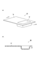
- FIG. 1 It is a perspective view which shows the process of manufacturing a secondary battery using the exterior material for electrical storage devices which concerns on one Embodiment of this invention, (a) shows the state which prepared the exterior material for electrical storage devices, (b) Is a state in which an exterior material for a power storage device processed into an embossed type and a battery element are prepared, and (c) is a state in which a part of the exterior material for a power storage device is folded and an end is melted. ) Shows a state where both sides of the folded portion are folded upward.
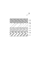
- FIG. 1 is a cross-sectional view schematically showing an embodiment of an exterior material for a power storage device of the present invention.
- an exterior material (exterior material for a power storage device) 10 of this embodiment includes a first base material layer 11 and a first adhesive layer 12 on one surface of the first base material layer 11. And a metal foil layer 15 formed on a surface of the second base material layer 13 opposite to the first base material layer 11 via a second adhesive layer 14. And a corrosion prevention treatment layer 16 formed on the surface of the metal foil layer 15 opposite to the second base material layer 13, and a surface of the corrosion prevention treatment layer 16 opposite to the metal foil layer 15.
- the first base material layer 11 is the outermost layer
- the sealant layer 18 is the innermost layer. That is, the exterior material 10 is used with the first base material layer 11 facing the outside of the power storage device and the sealant layer 18 facing the inside of the power storage device.
- FIG. 2 is a cross-sectional view schematically showing another embodiment of the packaging material for a power storage device of the present invention.
- the power storage device exterior material may have a single base layer. 2 includes a base material layer 21, a metal foil layer 15 formed on one surface of the base material layer 21 via an adhesive layer 22, and the metal.
- the corrosion prevention treatment layer 16 formed on the surface of the foil layer 15 opposite to the base material layer 21, and the sealant adhesive layer 17 on the surface of the corrosion prevention treatment layer 16 opposite to the metal foil layer 15.
- a sealant layer 18 formed in this manner.
- the base material layer 21 and the metal foil layer 15 are bonded together through only the adhesive layer 22 without any other base material layer interposed therebetween.
- the base material layer 21 is the outermost layer
- the sealant layer 18 is the innermost layer. That is, the exterior material 20 is used with the base material layer 21 facing the outside of the power storage device and the sealant layer 18 facing the inside of the power storage device.
- each layer which comprises the exterior materials 10 and 20 is demonstrated.
- the first base material layer 11 imparts heat resistance to the exterior material 10 in a pressurization thermal fusion process, which will be described later when manufacturing the power storage device, to suppress the occurrence of pinholes that may occur during processing or distribution.
- the first base material layer 11 is a layer configured to include a polyester resin containing a polyester elastomer and / or an amorphous polyester, and is also a layer that relaxes the shrinkage rate of the portion stretched by the molding process. .
- a polyester resin containing a polyester elastomer and / or amorphous polyester as a constituent material of the first base material layer 11, the upper yield point strength against tensile strain can be reduced, and the warpage after molding processing is greatly increased. Can be reduced.
- the polyester elastomer consists of a hard segment and a soft segment.
- the hard segment include crystalline polyesters such as polybutylene terephthalate, polybutylene naphthalate, and polyethylene terephthalate, and polybutylene terephthalate is particularly preferable from the viewpoint of flexibility.
- the soft segment include polyoxyalkylene glycols such as polytetramethylene glycol, and low-melting point polyesters such as polycaprolactone and polybutylene adipate. From the viewpoint of hydrolysis resistance, heat resistance, and low temperature characteristics, poly Tetramethylene glycol is preferred. These can be used individually by 1 type or in combination of 2 or more types.
- the polyester elastomer is a block copolymer of the hard segment and the soft segment.
- the copolymerization amount of the soft segment with respect to the hard segment is preferably 20 to 95% by mass, and more preferably 25 to 90% by mass, based on the total amount of the hard segment and the soft segment.
- the copolymerization amount of the soft segment is more than 20% by mass, the amount of warpage after molding of the exterior material tends to be further reduced, and the copolymerization amount of the soft segment is less than 95% by mass. Therefore, the heat resistance tends to be maintained at a high level.
- the amorphous polyester is a polyester resin in which no crystallinity is observed, or a polyester resin having low crystallinity and high transparency. Whether or not it corresponds to an amorphous polyester can be determined by, for example, the absence of a melting peak in differential scanning calorimetry.
- the polyester resin can be obtained by polycondensation of a polyhydric alcohol and a polycarboxylic acid, but an amorphous polyester can be obtained by selecting the polyhydric alcohol and polycarboxylic acid to be used.
- an amorphous polyester can be obtained by selecting the polyhydric alcohol and polycarboxylic acid to be used.
- polycondensation of terephthalic acid and ethylene glycol by changing a part of ethylene glycol to cyclohexanedimethanol, glycol-modified polyethylene terephthalate (PETG), which is an amorphous polyester, and glycol-modified polycyclohexylene diethylene are used.
- PETG polyethylene terephthalate
- PCTG Methylene terephthalate
- amorphous polyester examples include the above-described PETG and PCTG, as well as amorphous polyester obtained by heating and quenching when forming a PET film.
- PETG is preferable because amorphous polyester can be obtained without being influenced by the film forming method, and the extrusion moldability is good.
- PETG is preferable because amorphous polyester can be obtained without being influenced by the film forming method, and the extrusion moldability is good.
- PETG is preferable because amorphous polyester can be obtained without being influenced by the film forming method, and the extrusion moldability is good.
- These can be used individually by 1 type or in combination of 2 or more types.
- polyester resin used as a base material containing a polyester elastomer and / or amorphous polyester examples include polyethylene terephthalate, polybutylene terephthalate, polyethylene naphthalate, and polybutylene naphthalate. Among these, polyethylene terephthalate is preferable from the viewpoint of material cost.
- the content of the polyester elastomer is preferably 2 to 15% by mass, more preferably 5 to 10% by mass based on the total amount of the polyester resin containing the polyester elastomer. . If this content is 2% by mass or more, the amount of warping after molding of the exterior material tends to be further reduced, and if it is 15% by mass or less, heat resistance can be maintained at a high level. There is a tendency to be able to.
- the content of the amorphous polyester is preferably 20 to 60% by mass, and preferably 30 to 50% by mass based on the total amount of the polyester resin containing the amorphous polyester. It is more preferable that If this content is 20% by mass or more, the amount of warping after molding of the exterior material tends to be further reduced, and if it is 60% by mass or less, heat resistance can be maintained at a high level. There is a tendency to be able to.
- the first base material layer 11 may further contain other components as long as the effects of the present invention are not impaired in addition to the polyester resin containing the polyester elastomer and / or the amorphous polyester.
- other components include polyamide resin, polyolefin resin, polyimide resin, and polycarbonate resin.
- the first base material layer 11 including a polyester resin containing a polyester elastomer and / or an amorphous polyester is preferably a stretched film, and is excellent in puncture strength or impact strength, and is therefore polyester elastomer and / or amorphous.
- a biaxially stretched polyethylene terephthalate film containing polyester is more preferable.
- the thickness of the first base material layer 11 is preferably 4 to 20 ⁇ m, and more preferably 10 to 15 ⁇ m. There exists a tendency which can respond to thickness reduction by the thickness of the 1st base material layer 11 being 20 micrometers or less. Moreover, since the thickness of the 1st base material layer 11 is 4 micrometers or more, since the contraction rate of the location extended
- the first adhesive layer 12 is a layer that bonds the first base material layer 11 and the second base material layer 13 together.
- a bifunctional or higher functional aromatic or aliphatic isocyanate compound as a curing agent is used as a main agent composed of a compound having a hydroxyl group such as polyester polyol, polyether polyol, and acrylic polyol. It is preferable to use a two-component curable urethane adhesive that acts.
- the urethane adhesive is subjected to aging for 4 days or more, for example, at 40 ° C. after coating, whereby the reaction between the hydroxyl group of the main agent and the isocyanate group of the curing agent proceeds, and the first base material layer 11 and the second base layer 11 Strong adhesion with the base material layer 13 becomes possible.
- the thickness of the first adhesive layer 12 is preferably 1 to 10 ⁇ m, and more preferably 3 to 7 ⁇ m, from the viewpoint of adhesive strength, followability, workability, and the like.
- the second base material layer 13 is composed of a stretched polyamide film. Since the stretched polyamide film has high strength, large elongation and is soft, it can be formed into a thin and sharp molded shape. Therefore, the exterior material 10 including the second base material layer 13 can obtain more excellent moldability than the exterior material that does not include the second base material layer 13 like the exterior material 20.
- stretched polyamide film examples include nylon 6 film, nylon 11 film, nylon 12 film and the like. From the viewpoint of heat resistance, nylon 6 film is preferable, and biaxial from the viewpoint of excellent puncture strength or impact strength. A stretched nylon 6 (ONy) film is more preferable.
- the thickness of the second base material layer 13 is preferably 5 to 20 ⁇ m, and more preferably 10 to 15 ⁇ m.
- the thickness of the second base material layer 13 is 5 ⁇ m or more, excellent moldability tends to be obtained, and when it is 20 ⁇ m or less, the amount of warpage after molding of the exterior material can be further reduced. There is a tendency to be able to.
- the second adhesive layer 14 is a layer that bonds the second base material layer 13 and the metal foil layer 15 together.
- the adhesive constituting the second adhesive layer 14 is a main agent composed of a compound having a hydroxyl group such as polyester polyol, polyether polyol, acrylic polyol, etc., and a bifunctional or higher functional aromatic system as a curing agent.
- a two-component curable urethane adhesive that causes an aliphatic isocyanate compound to act.
- the urethane adhesive is subjected to aging at, for example, 40 ° C. for 4 days or more after coating, whereby the reaction between the hydroxyl group of the main agent and the isocyanate group of the curing agent proceeds, and the second base material layer 13 and the metal foil Strong adhesion to the layer 15 is possible.
- the thickness of the second adhesive layer 14 is preferably 1 to 10 ⁇ m, and more preferably 3 to 7 ⁇ m, from the viewpoint of adhesive strength, followability, workability, and the like.
- the base material layer 21 in the exterior material 20 is a layer that includes a polyester resin containing a polyester elastomer and / or an amorphous polyester.
- a polyester resin containing a polyester elastomer and / or amorphous polyester as a constituent material of the base material layer 21, it is possible to suppress the occurrence of pinholes or breakage in the exterior material 20 during molding, and good moldability Obtainable. Further, the upper yield point strength against tensile strain can be reduced, and the warpage after molding can be greatly reduced.
- the thickness of the substrate layer 21 is preferably 5 to 30 ⁇ m, and more preferably 10 to 25 ⁇ m.
- the thickness of the base material layer 21 is 30 ⁇ m or less, the shrinkage rate of the portion stretched by the molding processing on the base material layer 21 side can be more sufficiently suppressed, so that the shape after the molding processing is easily maintained. There is a tendency that the amount of warpage can be further reduced.
- the thickness of the base material layer 21 is 5 ⁇ m or more, it is possible to suppress the occurrence of pinholes or breakage in the exterior material at the time of molding, and good moldability can be obtained.
- the base material layer 21 can have the same configuration as the first base material layer 11 except for the thickness.
- the adhesive layer 22 is a layer that adheres the base material layer 21 and the metal foil layer 15.
- the adhesive constituting the adhesive layer 22 is a main agent composed of a compound having a hydroxyl group such as polyester polyol, polyether polyol, acrylic polyol, etc., and a bifunctional or higher functional aromatic or fat as a curing agent.
- a two-component curable urethane-based adhesive that causes the group-based isocyanate compound to act.
- the urethane adhesive is subjected to aging at 40 ° C. for 4 days or more after coating, whereby the reaction between the hydroxyl group of the main agent and the isocyanate group of the curing agent proceeds, and the base material layer 21 and the metal foil layer 15. Can be firmly bonded.
- the thickness of the adhesive layer 22 is preferably 1 to 10 ⁇ m, more preferably 3 to 7 ⁇ m, from the viewpoint of adhesive strength, followability, workability, and the like.
- Metal foil layer 15 examples include various metal foils such as aluminum and stainless steel, and the metal foil layer 15 is preferably an aluminum foil from the viewpoint of workability such as moisture resistance and spreadability, and cost.
- the aluminum foil may be a general soft aluminum foil, and is preferably an aluminum foil containing iron from the viewpoint of excellent pinhole resistance and extensibility during molding.
- the iron content is preferably 0.1 to 9.0% by mass, and more preferably 0.5 to 2.0% by mass.
- the iron content is 0.1% by mass or more, it is possible to obtain the exterior materials 10 and 20 having more excellent pinhole resistance and spreadability.
- the iron content is 9.0% by mass or less, it is possible to obtain exterior materials 10 and 20 that are more flexible.
- the thickness of the metal foil layer 15 is preferably 9 to 200 ⁇ m and more preferably 15 to 100 ⁇ m from the viewpoint of barrier properties, pinhole resistance and workability.
- the thickness of the metal foil layer 15 is 9 ⁇ m or more, the metal foil layer 15 is not easily broken even when stress is applied by molding.
- the thickness of the metal foil layer 15 is 200 ⁇ m or less, an increase in mass of the exterior material can be reduced, and a decrease in weight energy density of the power storage device can be suppressed.
- the corrosion prevention treatment layer 16 serves to suppress the corrosion of the metal foil layer 15 due to the electrolytic solution or hydrofluoric acid generated by the reaction between the electrolytic solution and moisture. Further, it plays a role of increasing the adhesion between the metal foil layer 15 and the sealant adhesive layer 17.
- the corrosion prevention treatment layer 16 is preferably a coating film formed by a coating type or immersion type acid-resistant corrosion prevention treatment agent. This coating film is excellent in the effect of preventing corrosion of the metal foil layer 15 against acid. Moreover, since the adhesive force between the metal foil layer 15 and the sealant adhesive layer 17 is further strengthened by the anchor effect, excellent resistance to power storage device elements such as an electrolytic solution can be obtained. Further, the corrosion prevention treatment layer 16 may be added between the second adhesive layer 14 or the adhesive layer 22 and the metal foil layer 15 according to a required function.
- the coating film of the corrosion inhibitor is, for example, ceriazol treatment with a corrosion inhibitor consisting of cerium oxide, phosphate and various thermosetting resins, and chromate, phosphate, fluoride and various thermosets. Formed by a chromate treatment with a corrosion prevention treatment agent composed of a conductive resin.
- the corrosion prevention treatment layer 16 is not limited to the above-described coating film as long as the corrosion resistance of the metal foil layer 15 is sufficiently obtained.
- the corrosion prevention treatment layer 16 may be a coating film formed by, for example, a phosphate treatment and a boehmite treatment.
- the corrosion prevention treatment layer 16 may be a single layer or a plurality of layers.
- an additive such as a silane coupling agent may be added to the corrosion prevention treatment layer 16.
- the thickness of the corrosion prevention treatment layer 16 is preferably, for example, 10 nm to 5 ⁇ m, and more preferably 20 to 500 nm, from the viewpoint of the corrosion prevention function and the function as an anchor.
- the sealant adhesive layer 17 is a layer for bonding the metal foil layer 15 on which the corrosion prevention treatment layer 16 is formed and the sealant layer 18.
- the exterior materials 10 and 20 are roughly classified into a thermal laminate configuration and a dry laminate configuration depending on the adhesive component that forms the sealant adhesive layer 17.
- the adhesive component for forming the sealant adhesive layer 17 in the heat laminate configuration is preferably an acid-modified polyolefin resin obtained by graft-modifying a polyolefin resin with an acid. Since the acid-modified polyolefin-based resin has a polar group introduced into a part of the non-polar polyolefin-based resin, the acid-modified polyolefin-based resin has a polarity with the sealant layer 18 formed of a non-polar polyolefin-based resin film or the like. In many cases, it can be firmly adhered to both of the corrosion prevention treatment layers 16.
- the use of the acid-modified polyolefin-based resin improves the resistance of the exterior materials 10 and 20 to the contents such as the electrolyte solution, and the adhesion due to deterioration of the sealant adhesive layer 17 even if hydrofluoric acid is generated inside the battery. It is easy to prevent the deterioration.
- polyolefin resin of the acid-modified polyolefin resin examples include low density, medium density and high density polyethylene; ethylene- ⁇ olefin copolymer; polypropylene; and propylene- ⁇ olefin copolymer.
- the polyolefin resin in the case of a copolymer may be a block copolymer or a random copolymer.
- a copolymer obtained by copolymerizing a polar molecule such as acrylic acid or methacrylic acid with the above-described one, or a polymer such as a crosslinked polyolefin can be used as the polyolefin resin.
- Examples of the acid that modifies the polyolefin resin include carboxylic acid, epoxy compound, and acid anhydride, and maleic anhydride is preferable.
- the acid-modified polyolefin resin used for the sealant adhesive layer 17 may be one type or two or more types.
- the heat-bonded sealant adhesive layer 17 can be formed by extruding the adhesive component with an extrusion device.
- the thickness of the heat-bonded sealant adhesive layer 17 is preferably 2 to 50 ⁇ m.
- an adhesive component for forming the sealant adhesive layer 17 having a dry laminate structure for example, a two-component curable polyurethane adhesive similar to that described for the first adhesive layer 12 and the second adhesive layer 14 may be used.
- the sealant adhesive layer 17 having a dry laminate structure has a highly hydrolyzable bonding portion such as an ester group and a urethane group
- a heat laminate structure is used as the sealant adhesive layer 17 for applications requiring higher reliability. It is preferable to use the adhesive component.
- the thickness of the sealant adhesive layer 17 is preferably 8 ⁇ m or more and 50 ⁇ m or less, and more preferably 20 ⁇ m or more and 40 ⁇ m or less.
- the thickness of the sealant adhesive layer 17 is 8 ⁇ m or more, sufficient adhesive strength between the metal foil layer 15 and the sealant layer 18 can be easily obtained. It is possible to easily reduce the amount of moisture that enters.
- the thickness of the sealant adhesive layer 17 is preferably 1 ⁇ m or more and 5 ⁇ m or less in the case of a dry laminate configuration.
- the thickness of the sealant adhesive layer 17 is 1 ⁇ m or more, sufficient adhesion strength between the metal foil layer 15 and the sealant layer 18 is easily obtained, and when the thickness is 5 ⁇ m or less, the sealant adhesive layer 17 is not cracked. Can be suppressed.
- the sealant layer 18 is a layer that imparts sealing properties to the exterior materials 10 and 20 by heat sealing.
- Examples of the sealant layer 18 include a polyolefin resin or a resin film made of an acid-modified polyolefin resin obtained by graft-modifying an acid such as maleic anhydride to a polyolefin resin.
- polystyrene resin examples include low density, medium density and high density polyethylene; ethylene- ⁇ olefin copolymer; polypropylene; and propylene- ⁇ olefin copolymer.
- the polyolefin resin in the case of a copolymer may be a block copolymer or a random copolymer. These polyolefin resin may be used individually by 1 type, and may use 2 or more types together.
- Examples of the acid-modified polyolefin resin include the same as those mentioned in the sealant adhesive layer 17.
- the sealant layer 18 may be a single layer film or a multilayer film, and may be selected according to a required function.
- a multilayer film in which a resin such as an ethylene-cycloolefin copolymer and polymethylpentene is interposed can be used.
- sealant layer 18 may contain various additives such as a flame retardant, a slip agent, an antiblocking agent, an antioxidant, a light stabilizer and a tackifier.
- the thickness of the sealant layer 18 is preferably 10 to 100 ⁇ m, and more preferably 20 to 60 ⁇ m. When the thickness of the sealant layer 18 is 20 ⁇ m or more, sufficient heat seal strength can be obtained, and when it is 90 ⁇ m or less, the amount of water vapor entering from the edge of the exterior material can be reduced.
- Step S ⁇ b> 11 A step of forming the corrosion prevention treatment layer 16 on one surface of the metal foil layer 15.
- Process S12 The process of bonding the 1st base material layer 11 and the 2nd base material layer 13 through the 1st contact bonding layer 12, and obtaining a laminated body.
- Step S13 The other surface of the metal foil layer 15 (the surface opposite to the side on which the corrosion prevention treatment layer 16 is formed) and the second adhesive layer 14 are interposed between the second base material layer 13 side of the laminate. The process of bonding the surface.
- Step S14 A step of forming a sealant layer 18 on the corrosion prevention treatment layer 16 via a sealant adhesive layer 17.
- step S ⁇ b> 11 the corrosion prevention treatment layer 16 is formed on one surface of the metal foil layer 15 by, for example, applying a corrosion prevention treatment agent on one surface of the metal foil layer 15 and drying.
- a corrosion prevention treatment agent examples include the above-described anti-corrosion treatment agent for ceriazole treatment and the anti-corrosion treatment agent for chromate treatment.
- the coating method of the corrosion inhibitor is not particularly limited, and various methods such as gravure coating, reverse coating, roll coating, and bar coating can be adopted.
- step S12 the second base material layer 13 is bonded to the first base material layer 11 by a technique such as dry lamination using an adhesive that forms the first adhesive layer 12.
- a technique such as dry lamination using an adhesive that forms the first adhesive layer 12.
- a laminate in which the one adhesive layer 12 and the second base material layer are laminated in this order is obtained.
- the aging time during which aging (curing) may be performed in the range of 40 ° C. to 100 ° C. to promote adhesion is, for example, 1 to 10 days.
- step S13 the other surface of the metal foil layer 15 (the surface opposite to the side on which the corrosion prevention treatment layer 16 is formed) and the adhesive for forming the second adhesive layer 14 are used by a technique such as dry lamination.
- the surface on the second base material layer 13 side of the laminate is bonded.
- an aging treatment (curing) may be performed in the range of 40 ° C. to 100 ° C. to promote adhesion.
- the aging time is, for example, 1 to 10 days.
- step S14 corrosion of the laminated body in which the first base material layer 11, the first adhesive layer 12, the second base material layer 13, the second adhesive layer 14, the metal foil layer 15, and the corrosion prevention treatment layer 16 are laminated in this order.
- a sealant layer 18 is formed on the prevention treatment layer 16 via a sealant adhesive layer 17.
- the sealant layer 18 may be laminated by dry lamination, sandwich lamination, or the like, or may be laminated together with the sealant adhesive layer 17 by a coextrusion method. From the viewpoint of improving adhesiveness, the sealant layer 18 is preferably laminated by sandwich lamination, for example, or is preferably laminated together with the sealant adhesive layer 17 by a coextrusion method, and more preferably laminated by sandwich lamination.
- the exterior material 10 is obtained through the steps S11 to S14 described above. Note that the process sequence of the manufacturing method of the packaging material 10 is not limited to the method of sequentially performing the above steps S11 to S14. For example, the order of steps to be performed may be changed as appropriate, such as step S11 after step S12.
- process S12 is not performed but in process S13, the other surface (the side where the corrosion prevention process layer 16 was formed is opposite).
- the side surface) and the base material layer 21 may be bonded together by a technique such as dry lamination using an adhesive that forms the adhesive layer 22.
- a technique such as dry lamination using an adhesive that forms the adhesive layer 22.
- the power storage device includes a battery element 1 including an electrode, a lead 2 extending from the electrode, and a container for housing the battery element 1, and the container includes a sealant layer 18 from the power storage device exterior materials 10 and 20. It is formed to be inside.
- the container may be obtained by stacking two exterior materials with the sealant layers 18 facing each other, and heat-sealing the peripheral portions of the overlaid exterior materials 10 and 20. It may be obtained by folding and superimposing and similarly heat-sealing the peripheral portions of the exterior materials 10 and 20.
- Examples of the power storage device include secondary batteries such as lithium ion batteries, nickel metal hydride batteries, and lead storage batteries, and electrochemical capacitors such as electric double layer capacitors.
- the lead 2 is sandwiched and sealed by exterior materials 10 and 20 that form a container with the sealant layer 18 inside.
- the lead 2 may be sandwiched between the exterior materials 10 and 20 via a tab sealant.
- FIG. 3 is a view showing the embossed type exterior member 30.
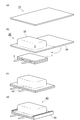
- FIGS. 4A to 4D are perspective views showing a manufacturing process of a one-side molded battery using the exterior material 10.
- the secondary battery 40 is a double-sided molded battery that is manufactured by bonding two exterior materials such as the embossed type exterior material 30 and bonding the exterior materials together while adjusting the alignment. Also good.
- the secondary battery 40 which is a one-side molded battery, can be manufactured by, for example, the following steps S21 to S25.
- Step S21 A step of preparing the outer packaging material 10, the battery element 1 including the electrodes, and the leads 2 extending from the electrodes.
- Step S22 A step of forming a recess 32 for disposing the battery element 1 on one side of the exterior material 10 (see FIG. 4A and FIG. 4B).
- Step S23 The battery element 1 is arranged in the molding processing area (recessed portion 32) of the embossed-type exterior member 30, and the embossed-type exterior member 30 is folded and overlapped so that the lid portion 34 covers the recessed portion 32, and extends from the battery element 1.
- Step S24 Leave one side other than the side sandwiching the lead 2 and pressurize and melt the other side, then inject the electrolyte from the remaining side and pressurize and heat-bond the remaining side in a vacuum state Step (see FIG. 4C).
- Step S25 A step of cutting the end portion of the heat-bonded side other than the side sandwiching the lead 2 and bending it to the side of the molding area (recess 32) (see FIG. 4D).
- step S21 the exterior material 10, the battery element 1 including the electrodes, and the leads 2 extending from the electrodes are prepared.
- the exterior material 10 is prepared based on the above-described embodiment. There is no restriction
- a recess 32 for disposing the battery element 1 on the sealant layer 18 side of the exterior material 10 is formed.
- the planar shape of the recess 32 is a shape that matches the shape of the battery element 1, for example, a rectangular shape in plan view.
- the recess 32 is formed, for example, by pressing a pressing member having a rectangular pressure surface against a part of the exterior material 10 in the thickness direction. Further, the pressing position, that is, the recess 32 is formed at a position deviated from the center of the exterior material 10 cut into a rectangle toward one end in the longitudinal direction of the exterior material 10. Thereby, the other end part side which does not form the recessed part 32 after a shaping
- a method of forming the recess 32 includes a molding process using a mold (deep drawing molding).
- a molding method a female mold and a male mold disposed so as to have a gap larger than the thickness of the exterior material 10 are used, and the male mold is pushed into the female mold together with the exterior material 10. Is mentioned.
- the embossed type exterior material 30 is obtained by forming the recess 32 in the exterior material 10.
- the embossed type exterior member 30 has a shape as shown in FIG. 3, for example.
- FIG. 3 (a) is a perspective view of the embossed type exterior member 30, and
- FIG. 3 (b) is a longitudinal section along the line bb of the embossed type exterior member 30 shown in FIG. 3 (a).
- step S23 In step S ⁇ b> 23, the battery element 1 including the positive electrode, the separator, the negative electrode, and the like is disposed in the molding processing area (recess 32) of the embossed type exterior material 30. Further, the lead 2 extending from the battery element 1 and bonded to the positive electrode and the negative electrode, respectively, is drawn out from the molding area (recess 32). Thereafter, the embossed type exterior member 30 is folded back at the approximate center in the longitudinal direction, and the sealant layers 18 are stacked so that the sealant layers 18 are on the inner side, and one side of the embossed type exterior member 30 sandwiching the lead 2 is subjected to pressure heat fusion.
- the pressure heat fusion is controlled by three conditions of temperature, pressure, and time, and is appropriately set. The temperature of the pressure heat fusion is preferably equal to or higher than the temperature at which the sealant layer 18 is melted.
- the thickness of the sealant layer 18 before heat sealing is preferably 40% or more and 80% or less with respect to the thickness of the lead 2.
- the heat-sealing resin tends to sufficiently fill the end of the lead 2, and when the thickness is equal to or less than the upper limit value, the exterior material 10 of the secondary battery 40.
- the thickness of the end can be moderately suppressed, and the amount of moisture permeating from the end of the exterior material 10 can be reduced.
- step S24 one side other than the side sandwiching the lead 2 is left and the other side is subjected to pressure heat fusion. Thereafter, an electrolytic solution is injected from the remaining side, and the remaining side is pressurized and heat-sealed in a vacuum state. The conditions for the pressure heat fusion are the same as in step S23.
- Step S25 The peripheral pressurizing and heat-bonding side end other than the side sandwiching the lead 2 is cut, and the sealant layer 18 protruding from the end is removed. Then, the secondary battery 40 is obtained by folding the peripheral pressure heat-sealed portion toward the molding area 32 and forming the folded portion 42.
- the exterior material 20 when manufacturing an electrical storage apparatus using the exterior material 20, the exterior material 20 should just be used instead of the exterior material 10 in the manufacturing method of the electrical storage apparatus using the exterior material 10 mentioned above.
- Adhesive B-1 Polyester urethane adhesive (trade name “Takelac / Takenate”, manufactured by Mitsui Chemicals)
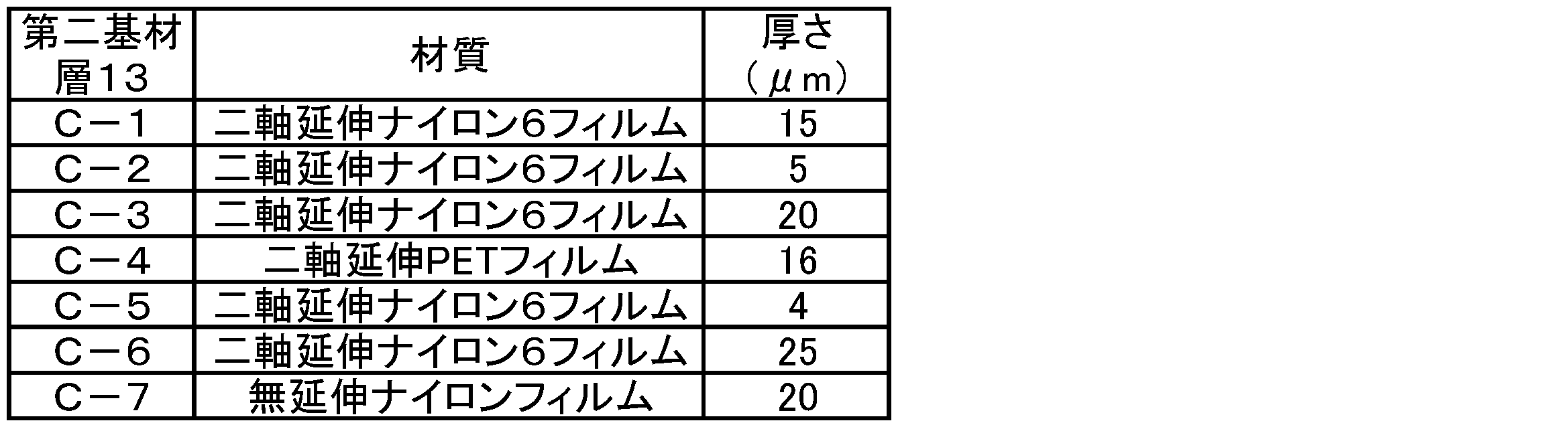
- the substrate C-4 a biaxially stretched PET film (trade name “Lumirror”, manufactured by Toray Film Processing Co., Ltd.) is used, and as the substrate C-7, an unstretched nylon film (trade name “Die” Amylon C ”(manufactured by Mitsubishi Plastics) was used.
- Adhesive D-1 Polyester urethane adhesive (trade name “Takelac / Takenate”, manufactured by Mitsui Chemicals)
- Metal foil layer 15 Metal foil E-1: Soft aluminum foil 8079 material (Toyo Aluminum Co., Ltd., thickness 40 ⁇ m)
- Treatment agent F-1 Treatment agent for coating type ceriazole treatment mainly composed of cerium oxide, phosphoric acid and acrylic resin.
- Adhesive resin G-1 Polypropylene resin graft-modified with maleic anhydride (trade name “Admer”, manufactured by Mitsui Chemicals, Inc.)
- Film H-1 Film obtained by corona-treating the inner surface of an unstretched polypropylene film (thickness 60 ⁇ m) (trade name “GHC”, manufactured by Mitsui Chemicals, Inc.)
- Treatment agent F-1 was applied to one surface of metal foil E-1 to be metal foil layer 15 and dried to form corrosion prevention treatment layer 16.
- the base material A-1 to A-10, A-17, A-19, A-21 to A-27 to be the base material layer 21 is formed on the opposite surface of the metal foil layer 15 to the corrosion prevention treatment layer 16.
- Either one was attached by a dry laminating method using adhesive B-1.
- the second base material layer is formed by a dry laminating method using an adhesive B-1 on any of the base materials A-11 to A-20 and A-28 to A-34 to be the first base material layer 11.
- the 2nd base material layer 13 side in the laminated body of the 1st base material layer 11, the 1st contact bonding layer 12, and the 2nd base material layer 13 was bonded together. Thereafter, aging was performed at 60 ° C. for 6 days.
- the adhesive resin G-1 is extruded to the side of the corrosion prevention treatment layer 16 of the obtained laminate by an extrusion device to form a sealant adhesive layer 17, and the film H-1 is bonded and sandwich lamination is performed. Layer 18 was formed.
- the obtained laminates were subjected to thermocompression bonding at 190 ° C. to produce exterior materials of Examples 1 to 41 and Comparative Examples 1 to 5.
- the thickness of the adhesive layer 22 after lamination is 5 ⁇ m
- the thickness of the first adhesive layer 12 after lamination is 5 ⁇ m
- the thickness of the second adhesive layer 14 after lamination is 5 ⁇ m
- the thickness of the sealant adhesive layer 17 was 25 ⁇ m.
- Table 3 shows the types of base materials used in each example.
- the exterior materials obtained in the examples and comparative examples were cut into a 120 mm ⁇ 260 mm rectangular shape and placed in a molding apparatus so that the sealant layer faced upward.
- the molding depth of the molding apparatus was set to 3 mm, and cold molding was performed in an environment with a room temperature of 23 ° C. and a dew point temperature of ⁇ 35 ° C.
- Use a punch die that has a rectangular cross section of 70 mm x 80 mm, a punch radius (RP) of 0.75 mm on the bottom, and a punch corner radius (RCP) of 1.5 mm on the side did. Further, a die having a 0.75 mm diradius (RD) on the upper surface of the opening was used.
- RP punch radius
- RCP punch corner radius
- the clearance between the punch mold and the die mold was 0.2 mm.
- the molding area was the approximate center of the half surface divided by the approximate center in the longitudinal direction of the cut exterior material. That is, the molding area was arranged so that both ends of the molding area were positioned at 25 mm from both ends in the short direction of the cut exterior material.
- the molded exterior material is allowed to stand on a horizontal table for 60 minutes in an environment with a room temperature of 23 ° C and a dew point of -35 ° C so that the first base material layer 11 side faces upward.
- the maximum value of the distance from the side table in the short direction was measured, and the measured value was taken as the amount of warpage.
- the amount of warpage was evaluated according to the following evaluation criteria. The results are shown in Table 3.
- B The amount of warpage was 50 mm or more and less than 75 mm.
- C The amount of warpage was 75 mm or more and less than 100 mm.
- D The amount of warpage was 100 mm or more.
- the exterior materials obtained in the examples and comparative examples were cut into a 150 mm ⁇ 190 mm rectangular shape and placed in a molding apparatus so that the sealant layer faced upward.
- the molding depth of the molding apparatus was set to 1 to 10 mm every 1 mm, and cold molding was performed in an environment of room temperature 23 ° C. and dew point temperature ⁇ 35 ° C., and the moldability at each molding depth was evaluated according to the following criteria.
- the punch mold has a rectangular cross section of 100 mm ⁇ 150 mm, has a punch radius (RP) of 0.75 mm on the bottom surface, and a punch corner radius (RCP) of 1.5 mm on the side surface. It was used.
- a die having a 0.75 mm diradius (RD) on the upper surface of the opening was used.
- the molding depth was evaluated according to the following evaluation criteria. The results are shown in Table 3.
- D Breaking or cracking occurs in deep drawing with a molding depth of less than 4 mm.
- SYMBOLS 1 Battery element, 2 ... Lead, 10 ... Exterior material (exterior material for electrical storage devices), 11 ... First base material layer, 12 ... First adhesive layer, 13 ... Second base material layer, 14 ... Second adhesive layer 15 ... Metal foil layer, 16 ... Corrosion prevention treatment layer, 17 ... Sealant adhesive layer, 18 ... Sealant layer, 21 ... Base material layer, 22 ... Adhesive layer, 30 ... Embossed type exterior material, 32 ... Molding processing area (recessed portion) ), 34 ... lid, 40 ... secondary battery.
Landscapes
- Chemical & Material Sciences (AREA)
- Chemical Kinetics & Catalysis (AREA)
- Electrochemistry (AREA)
- General Chemical & Material Sciences (AREA)
- Engineering & Computer Science (AREA)
- Power Engineering (AREA)
- Microelectronics & Electronic Packaging (AREA)
- Inorganic Chemistry (AREA)
- Mechanical Engineering (AREA)
- Manufacturing & Machinery (AREA)
- Materials Engineering (AREA)
- Sealing Battery Cases Or Jackets (AREA)
- Electric Double-Layer Capacitors Or The Like (AREA)
- Laminated Bodies (AREA)
Abstract
Description
図1は、本発明の蓄電装置用外装材の一実施形態を模式的に表す断面図である。図1に示すように、本実施形態の外装材(蓄電装置用外装材)10は、第一基材層11と、該第一基材層11の一方の面上に第一接着層12を介して形成された第二基材層13と、該第二基材層13の上記第一基材層11とは反対の面上に第二接着層14を介して形成された金属箔層15と、該金属箔層15の上記第二基材層13とは反対の面上に形成された腐食防止処理層16と、該腐食防止処理層16の金属箔層15とは反対の面上にシーラント接着層17を介して形成されたシーラント層18と、が順次積層された積層体である。外装材10は、第一基材層11が最外層、シーラント層18が最内層である。すなわち、外装材10は、第一基材層11を蓄電装置の外部側、シーラント層18を蓄電装置の内部側に向けて使用される。
第一基材層11は、蓄電装置を製造する際の後述する加圧熱融着工程における耐熱性を外装材10に付与し、加工又は流通の際に起こり得るピンホールの発生を抑制するための層である。また、第一基材層11は、ポリエステルエラストマー及び/又は非晶質ポリエステルを含有するポリエステル樹脂を含んで構成される層であり、成型加工により延伸された部分の収縮率を緩和する層でもある。第一基材層11の構成材料としてポリエステルエラストマー及び/又は非晶質ポリエステルを含有するポリエステル樹脂を用いることにより、引張り歪みに対する上降伏点強度を小さくすることができ、成型加工後の反りを大幅に低減することができる。
第一接着層12は、第一基材層11と第二基材層13とを接着する層である。第一接着層12に用いられる接着材としては、ポリエステルポリオール、ポリエーテルポリオール、アクリルポリオール等の水酸基を有する化合物からなる主剤に、硬化剤として2官能以上の芳香族系又は脂肪族系イソシアネート化合物を作用させる2液硬化型のウレタン系接着剤を用いることが好ましい。上記ウレタン系接着剤は、塗工後、例えば40℃で4日以上のエージングを行うことで、主剤の水酸基と硬化剤のイソシアネート基との反応が進行し、第一基材層11と第二基材層13との強固な接着が可能となる。
第二基材層13は、延伸ポリアミドフィルムで構成される。延伸ポリアミドフィルムは、強度が高く、伸びが大きく、且つ軟質であるため、薄肉で、シャープな成型加工形状を形成することができる。そのため、第二基材層13を備える外装材10は、外装材20のように第二基材層13を備えない外装材と比較して、より優れた成形性を得ることができる。
第二接着層14は、第二基材層13と金属箔層15とを接着する層である。第二接着層14を構成する接着剤は、第一接着層12と同様、ポリエステルポリオール、ポリエーテルポリオール、アクリルポリオール等の水酸基を有する化合物からなる主剤に、硬化剤として2官能以上の芳香族系又は脂肪族系イソシアネート化合物を作用させる2液硬化型のウレタン系接着剤を用いることが好ましい。上記ウレタン系接着剤は、塗工後、例えば40℃で4日以上のエージングを行うことで、主剤の水酸基と硬化剤のイソシアネート基との反応が進行し、第二基材層13と金属箔層15との強固な接着が可能となる。
外装材20における基材層21は、第一基材層11と同様に、ポリエステルエラストマー及び/又は非晶質ポリエステルを含有するポリエステル樹脂を含んで構成される層である。基材層21の構成材料としてポリエステルエラストマー及び/又は非晶質ポリエステルを含有するポリエステル樹脂を用いることにより、成型時に外装材20にピンホール又は破断等が生じることを抑制でき、良好な成型性を得ることができる。また、引張り歪みに対する上降伏点強度を小さくすることができ、成型加工後の反りを大幅に低減することができる。
接着層22は、基材層21と金属箔層15とを接着する層である。接着層22を構成する接着剤は、第一接着層12と同様、ポリエステルポリオール、ポリエーテルポリオール、アクリルポリオール等の水酸基を有する化合物からなる主剤に、硬化剤として2官能以上の芳香族系又は脂肪族系イソシアネート化合物を作用させる2液硬化型のウレタン系接着剤を用いることが好ましい。上記ウレタン系接着剤は、塗工後、例えば40℃で4日以上のエージングを行うことで、主剤の水酸基と硬化剤のイソシアネート基との反応が進行し、基材層21と金属箔層15との強固な接着が可能となる。
金属箔層15としては、アルミニウム及びステンレス鋼等の各種金属箔が挙げられ、防湿性及び延展性等の加工性、並びにコストの面から、金属箔層15はアルミニウム箔であることが好ましい。アルミニウム箔は一般の軟質アルミニウム箔であってもよく、耐ピンホール性及び成形時の延展性に優れる点から、鉄を含むアルミニウム箔であることが好ましい。
腐食防止処理層16は、電解液、又は、電解液と水分の反応により発生するフッ酸による金属箔層15の腐食を抑制する役割を果たす。また、金属箔層15とシーラント接着層17との密着力を高める役割を果たす。
シーラント接着層17は、腐食防止処理層16が形成された金属箔層15とシーラント層18を接着する層である。外装材10,20は、シーラント接着層17を形成する接着成分によって、熱ラミネート構成とドライラミネート構成に大きく分けられる。
シーラント層18は、外装材10,20に対し、ヒートシールによる封止性を付与する層である。シーラント層18としては、ポリオレフィン系樹脂、又はポリオレフィン系樹脂に無水マレイン酸等の酸をグラフト変性させた酸変性ポリオレフィン系樹脂からなる樹脂フィルムが挙げられる。
次に、外装材10の製造方法について説明する。なお、外装材10の製造方法は以下の方法に限定されない。
工程S11:金属箔層15の一方の面上に腐食防止処理層16を形成する工程。
工程S12:第一基材層11と第二基材層13とを第一接着層12を介して貼り合わせ、積層体を得る工程。
工程S13:金属箔層15の他方の面(腐食防止処理層16を形成した側と反対側の面)と、第二接着層14を介して、上記積層体の第二基材層13側の面とを貼り合わせる工程。
工程S14:腐食防止処理層16上に、シーラント接着層17を介してシーラント層18を形成する工程。
工程S11では、腐食防止処理層16は、例えば、金属箔層15の一方の面上に腐食防止処理剤を塗布し、乾燥することにより、金属箔層15の一方の面上を形成される。腐食防止処理剤としては、例えば、上述のセリアゾール処理用の腐食防止処理剤、クロメート処理用の腐食防止処理剤等が挙げられる。腐食防止処理剤の塗布方法は特に限定されず、グラビアコート、リバースコート、ロールコート、又はバーコート等の各種方法を採用できる。
工程S12では、第一基材層11に第一接着層12を形成する接着剤を用いて、ドライラミネーション等の手法で第二基材層13が貼り合わせられ、第一基材層11、第一接着層12及び第二基材層がこの順に積層された積層体が得られる。工程S12では、接着性の促進のため、40℃~100℃の範囲でエージング(養生)を行ってもよいエージング時間は、例えば、1~10日である。
工程S13では、金属箔層15の他方の面(腐食防止処理層16を形成した側と反対側の面)と、第二接着層14を形成する接着剤を用いて、ドライラミネーション等の手法で上記積層体の第二基材層13側の面とが貼り合わせられる。工程S13では、接着性の促進のため、40℃~100℃の範囲でエージング(養生)処理を行ってもよい。エージング時間は、例えば、1~10日である。
工程S13後、第一基材層11、第一接着層12、第二基材層13、第二接着層14、金属箔層15及び腐食防止処理層16がこの順に積層された積層体の腐食防止処理層16上に、シーラント接着層17を介してシーラント層18が形成される。シーラント層18は、ドライラミネーション及びサンドイッチラミネーション等によって積層されてもよく、シーラント接着層17とともに共押出し法によって積層されてもよい。シーラント層18は、接着性向上の点から、例えばサンドイッチラミネーションによって積層される、又は、シーラント接着層17とともに共押出し法によって積層されることが好ましく、サンドイッチラミネーションによって積層されることがより好ましい。
次に、外装材10,20を容器として備える蓄電装置について説明する。蓄電装置は、電極を含む電池要素1と、上記電極から延在するリード2と、電池要素1を収容する容器とを備え、上記容器は蓄電装置用外装材10,20から、シーラント層18が内側となるように形成される。上記容器は、2つの外装材をシーラント層18同士を対向させて重ね合わせ、重ねられた外装材10,20の周縁部を熱融着して得られてもよく、また、1つの外装材を折り返して重ね合わせ、同様に外装材10,20の周縁部を熱融着して得られてもよい。蓄電装置としては、例えば、リチウムイオン電池、ニッケル水素電池、及び鉛蓄電池等の二次電池、並びに電気二重層キャパシタ等の電気化学キャパシタが挙げられる。
次に、上述した外装材10を用いて蓄電装置を製造する方法について説明する。なお、ここでは、エンボスタイプ外装材30を用いて二次電池40を製造する場合を例に挙げて説明する。図3は上記エンボスタイプ外装材30を示す図である。図4の(a)~(d)は、外装材10を用いた片側成型加工電池の製造工程を示す斜視図である。二次電池40としては、エンボスタイプ外装材30のような外装材を2つ設け、このような外装材同士を、アライメントを調整しつつ、貼り合わせて製造される、両側成型加工電池であってもよい。
工程S21:外装材10、電極を含む電池要素1、並びに上記電極から延在するリード2を準備する工程。
工程S22:外装材10の片面に電池要素1を配置するための凹部32を形成する工程(図4(a)及び図4(b)参照)。
工程S23:エンボスタイプ外装材30の成型加工エリア(凹部32)に電池要素1を配置し、凹部32を蓋部34が覆うようにエンボスタイプ外装材30を折り返し重ねて、電池要素1から延在するリード2を挟持するようにエンボスタイプ外装材30の一辺を加圧熱融着する工程(図4(b)及び図4(c)参照)。
工程S24:リード2を挟持する辺以外の一辺を残し、他の辺を加圧熱融着し、その後、残った一辺から電解液を注入し、真空状態で残った一辺を加圧熱融着する工程(図4(c)参照)。
工程S25:リード2を挟持する辺以外の加圧熱融着辺端部をカットし、成型加工エリア(凹部32)側に折り曲げる工程(図4(d)参照)。
工程S21では、外装材10、電極を含む電池要素1、並びに上記電極から延在するリード2を準備する。外装材10は、上述した実施形態に基づき準備する。電池要素1及びリード2としては特に制限はなく、公知の電池要素1及びリード2を用いることができる。
工程S22では、外装材10のシーラント層18側に電池要素1を配置するための凹部32が形成される。凹部32の平面形状は、電池要素1の形状に合致する形状、例えば平面視矩形状とされる。凹部32は、例えば矩形状の圧力面を有する押圧部材を、外装材10の一部に対してその厚み方向に押圧することで形成される。また、押圧する位置、すなわち凹部32は、長方形に切り出した外装材10の中央より、外装材10の長手方向の一方の端部に偏った位置に形成する。これにより、成型加工後に凹部32を形成していないもう片方の端部側を折り返し、蓋(蓋部34)とすることができる。
工程S23では、エンボスタイプ外装材30の成型加工エリア(凹部32)内に、正極、セパレータ及び負極等から構成される電池要素1が配置され。また、電池要素1から延在し、正極と負極にそれぞれ接合されたリード2が成型加工エリア(凹部32)から外に引き出される。その後、エンボスタイプ外装材30は、長手方向の略中央で折り返され、シーラント層18同士が内側となるように重ねられ、エンボスタイプ外装材30のリード2を挟持する一辺が加圧熱融着される。加圧熱融着は、温度、圧力及び時間の3条件で制御され、適宜設定される。加圧熱融着の温度は、シーラント層18を融解する温度以上であることが好ましい。
工程S24では、リード2を挟持する辺以外の一辺を残し、他の辺の加圧熱融着が行われる。その後、残った一辺から電解液を注入し、残った一辺が真空状態で加圧熱融着される。加圧熱融着の条件は工程S23と同様である。
リード2を挟持する辺以外の周縁加圧熱融着辺端部がカットされ、端部からははみだしたシーラント層18が除去される。その後、周縁加圧熱融着部を成型加工エリア32側に折り返し、折り返し部42を形成することで、二次電池40が得られる。
実施例及び比較例で使用した材料を以下に示す。
(第一基材層11又は基材層21)
下記表1に示す基材を用いた。

接着剤B-1:ポリエステルウレタン系接着剤(商品名「タケラック/タケネート」、三井化学社製)
下記表2に示す基材を用いた。
接着剤D-1:ポリエステルウレタン系接着剤(商品名「タケラック/タケネート」、三井化学社製)
金属箔E-1:軟質アルミニウム箔8079材(東洋アルミニウム社製、厚さ40μm)
処理剤F-1:酸化セリウム、リン酸、アクリル系樹脂を主体とした塗布型セリアゾール処理用の処理剤。
接着樹脂G-1:無水マレイン酸でグラフト変性したポリプロピレン系樹脂(商品名「アドマー」、三井化学社製)
フィルムH-1:無延伸ポリプロピレンフィルム(厚さ60μm)の内面となる側の面をコロナ処理したフィルム(商品名「GHC」、三井化学東セロ社製)
(外装材の作製)
金属箔層15となる金属箔E-1の一方の面に処理剤F-1を塗布、乾燥して腐食防止処理層16を形成した。次に、金属箔層15における腐食防止処理層16の反対面に、基材層21となる基材A-1~A-10、A-17、A-19、A-21~A-27のいずれかを、接着剤B-1を用いたドライラミネート法により貼り付けた。また、第一基材層11となる基材A-11~A-20、A-28~A-34のいずれかに、接着剤B-1を用いたドライラミネート法により、第二基材層13となる基材C-1~C-7のいずれかを貼り合わせ、次に、金属箔層15における腐食防止処理層16の反対面に、接着剤D-1を用いたドライラミネート法により、第一基材層11、第一接着層12及び第二基材層13の積層体における第二基材層13側を貼り合わせた。その後、60℃、6日間のエージングを行った。次に、得られた積層体の腐食防止処理層16側に押出し装置にて接着樹脂G-1を押出してシーラント接着層17を形成し、フィルムH-1を貼り合わせてサンドイッチラミネーションすることでシーラント層18を形成した。その後、得られた積層体に対し、190℃で加熱圧着することで実施例1~41及び比較例1~5の外装材を作製した。なお、積層後の接着層22の厚さは5μmであり、積層後の第一接着層12の厚さは5μmであり、積層後の第二接着層14の厚さは5μmであり、積層後のシーラント接着層17の厚さは25μmであった。各例において使用した基材の種類を表3に示す。
実施例及び比較例で得られた外装材を、120mm×260mmの矩形状に切り取り、シーラント層が上方を向くように成型装置内に配置した。成型装置の成型深さを3mmに設定し、室温23℃、露点温度-35℃の環境下で、冷間成型を行った。パンチ金型には、70mm×80mmの長方形の横断面を有し、底面に0.75mmのパンチラジアス(RP)を有し、側面に1.5mmのパンチコーナーラジアス(RCP)を有するものを使用した。また、ダイ金型には、開口部上面に0.75mmのダイラジアス(RD)を有するものを使用した。パンチ金型とダイ金型との間のクリアランスは0.2mmとした。成型エリアは切り取った外装材の長手方向の略中央で分けた半面の略中央とした。すなわち、成型エリアの両端が、切り取った外装材の短手方向の両端からそれぞれ25mmの位置となるように、成型エリアを配置した。
A:反り量が50mm未満であった。
B:反り量が50mm以上75mm未満であった。
C:反り量が75mm以上100mm未満であった。
D:反り量が100mm以上であった。
実施例及び比較例で得られた外装材を、150mm×190mmの矩形状に切り取り、シーラント層が上方を向くように成型装置内に配置した。成型装置の成型深さを1mmごとに1~10mmに設定し、室温23℃、露点温度-35℃の環境下で冷間成型し、各成型深さにおける成型性を下記基準に従って評価した。なお、パンチ金型には、100mm×150mmの長方形の横断面を有し、底面に0.75mmのパンチラジアス(RP)を有し、側面に1.5mmのパンチコーナーラジアス(RCP)を有するものを使用した。また、ダイ金型には、開口部上面に0.75mmのダイラジアス(RD)を有するものを使用した。成型深さの評価は、以下の評価基準に従って行った。結果を表3に示す。
A:破断又はクラックを生じずに、成型深さ6mm以上の深絞り成型が可能である。
B:破断又はクラックを生じずに、成型深さ5mm以上6mm未満の深絞り成型が可能である。
C:破断又はクラックを生じずに、成型深さ4mm以上5mm未満の深絞り成型が可能である。
D:成型深さ4mm未満の深絞り成型で破断又はクラックが生じる。
実施例及び比較例で得られた外装材を、50mm×200mmの短冊状に二枚切り取った。そして、切り取ったサンプルの基材層同士を向い合わせた状態で、200℃又は210℃に加温したヒートシールバーで10秒間挟み込み、基材層同士が接着しているかを評価した。耐熱性の評価は、以下の評価基準に従って行った。結果を表3に示す。
A:ヒートシール温度210℃でも接着していなかった。
B:ヒートシール温度200℃で接着していなかったが、210℃で接着していた。
C:ヒートシール温度200℃で接着していた。
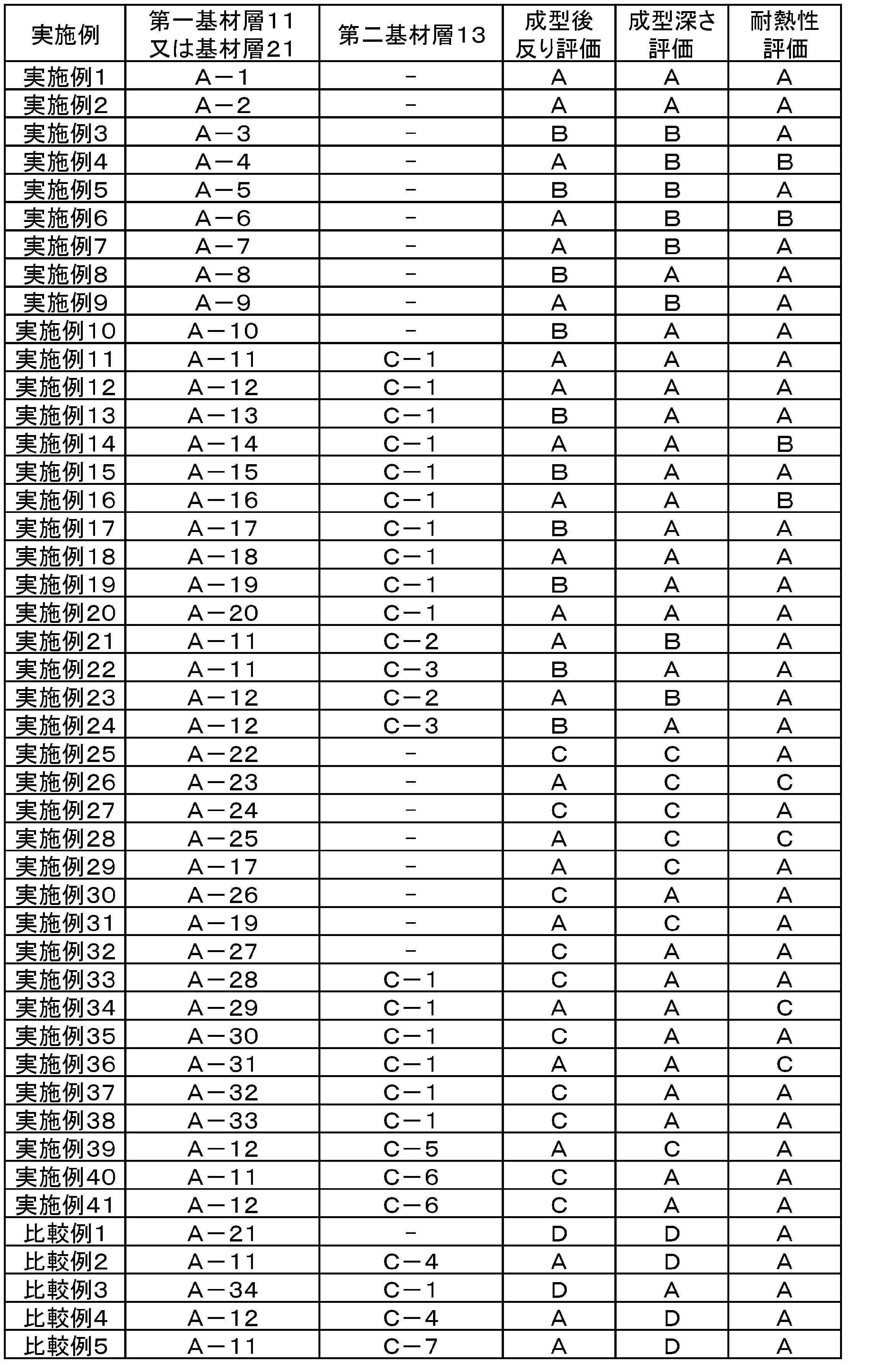
Claims (6)
- 基材層と、該基材層の一方の面上に接着層を介して形成された金属箔層と、該金属箔層の前記基材層とは反対の面上に配置されたシーラント層とを備え、
前記基材層が、ポリエステルエラストマー及び/又は非晶質ポリエステルを含有するポリエステル樹脂を含む層である、蓄電装置用外装材。 - 前記基材層の厚さが5μm以上30μm以下である、請求項1に記載の蓄電装置用外装材。
- 第一基材層と、該第一基材層の一方の面上に第一接着層を介して形成された第二基材層と、該第二基材層の前記第一基材層とは反対の面上に第二接着層を介して形成された金属箔層と、該金属箔層の前記第二基材層とは反対の面上に配置されたシーラント層とを備え、
前記第一基材層が、ポリエステルエラストマー及び/又は非晶質ポリエステルを含有するポリエステル樹脂を含む層であり、
前記第二基材層が、延伸ポリアミドフィルムである、蓄電装置用外装材。 - 前記第一基材層の厚さが4μm以上20μm以下であり、且つ、前記第二基材層の厚さが5μm以上20μm以下である、請求項3に記載の蓄電装置用外装材。
- 前記ポリエステル樹脂中の前記ポリエステルエラストマーの含有量が、前記ポリエステル樹脂の全量を基準として2~15質量%である、又は、前記非晶質ポリエステルの含有量が、前記ポリエステル樹脂の全量を基準として20~60質量%である、請求項1~4のいずれか一項に記載の蓄電装置用外装材。
- 電極を含む電池要素と、前記電極から延在するリードと、前記電池要素を収容する容器とを備え、
前記容器は請求項1~5のいずれか一項に記載の蓄電装置用外装材から、前記シーラント層が内側となるように形成されている、蓄電装置。
Priority Applications (6)
| Application Number | Priority Date | Filing Date | Title |
|---|---|---|---|
| KR1020187028143A KR102017446B1 (ko) | 2014-04-24 | 2015-04-22 | 축전 장치용 외장재 및 그것을 사용한 축전 장치 |
| KR1020167032212A KR20160146869A (ko) | 2014-04-24 | 2015-04-22 | 축전 장치용 외장재 및 그것을 사용한 축전 장치 |
| EP15783412.8A EP3121864B1 (en) | 2014-04-24 | 2015-04-22 | Storage battery device outer-package material and storage battery device using same |
| JP2016515184A JP6990972B2 (ja) | 2014-04-24 | 2015-04-22 | 蓄電装置用外装材、及びそれを用いた蓄電装置 |
| CN201580021469.6A CN106233492B (zh) | 2014-04-24 | 2015-04-22 | 蓄电装置用封装材料及使用其的蓄电装置 |
| US15/331,289 US9941493B2 (en) | 2014-04-24 | 2016-10-21 | Power storage device package material and storage device using the same |
Applications Claiming Priority (2)
| Application Number | Priority Date | Filing Date | Title |
|---|---|---|---|
| JP2014-090022 | 2014-04-24 | ||
| JP2014090022 | 2014-04-24 |
Related Child Applications (1)
| Application Number | Title | Priority Date | Filing Date |
|---|---|---|---|
| US15/331,289 Continuation US9941493B2 (en) | 2014-04-24 | 2016-10-21 | Power storage device package material and storage device using the same |
Publications (1)
| Publication Number | Publication Date |
|---|---|
| WO2015163371A1 true WO2015163371A1 (ja) | 2015-10-29 |
Family
ID=54332534
Family Applications (1)
| Application Number | Title | Priority Date | Filing Date |
|---|---|---|---|
| PCT/JP2015/062257 Ceased WO2015163371A1 (ja) | 2014-04-24 | 2015-04-22 | 蓄電装置用外装材、及びそれを用いた蓄電装置 |
Country Status (7)
| Country | Link |
|---|---|
| US (1) | US9941493B2 (ja) |
| EP (1) | EP3121864B1 (ja) |
| JP (2) | JP6990972B2 (ja) |
| KR (2) | KR20160146869A (ja) |
| CN (1) | CN106233492B (ja) |
| TW (1) | TWI671186B (ja) |
| WO (1) | WO2015163371A1 (ja) |
Cited By (7)
| Publication number | Priority date | Publication date | Assignee | Title |
|---|---|---|---|---|
| WO2016060228A1 (ja) * | 2014-10-16 | 2016-04-21 | 凸版印刷株式会社 | 蓄電デバイス用外装材及び蓄電デバイス |
| KR101987893B1 (ko) * | 2018-01-25 | 2019-06-12 | 율촌화학 주식회사 | 내화학성 및 밴딩성이 개선된 셀 파우치 |
| JPWO2018066670A1 (ja) * | 2016-10-05 | 2019-07-25 | 大日本印刷株式会社 | 電池用包装材料、その製造方法、及び電池 |
| CN111133603A (zh) * | 2017-10-06 | 2020-05-08 | 大日本印刷株式会社 | 电池用包装材料和电池 |
| JP2020113368A (ja) * | 2019-01-08 | 2020-07-27 | 凸版印刷株式会社 | 蓄電デバイス用外装材 |
| JP2023538385A (ja) * | 2020-08-19 | 2023-09-07 | エルジー エナジー ソリューション リミテッド | パウチ型電池ケースおよびパウチ型二次電池 |
| US12244023B2 (en) | 2020-08-19 | 2025-03-04 | Lg Energy Solution, Ltd. | Pouch-type battery case and pouch type secondary battery |
Families Citing this family (8)
| Publication number | Priority date | Publication date | Assignee | Title |
|---|---|---|---|---|
| JP6458338B2 (ja) * | 2013-11-01 | 2019-01-30 | 凸版印刷株式会社 | 二次電池用外装材、二次電池、及び二次電池用外装材の製造方法 |
| US11426986B2 (en) | 2017-03-21 | 2022-08-30 | Dai Nippon Printing Co., Ltd. | Packaging material for batteries, method for producing same, polybutylene terephthalate film for packaging material for batteries, and battery |
| KR20210068073A (ko) * | 2018-10-01 | 2021-06-08 | 다이니폰 인사츠 가부시키가이샤 | 축전 디바이스용 외장재, 그 제조 방법, 및 축전 디바이스 |
| ES3053077T3 (en) | 2018-12-21 | 2026-01-19 | Tata Steel Ijmuiden Bv | Method for producing a polymer coated metal strip and polymer coated metal strip produced thereby |
| US12506197B2 (en) | 2020-03-12 | 2025-12-23 | Dai Nippon Printing Co., Ltd. | Outer package material for all-solid-state batteries, method for producing same and all-solid-state battery |
| US20240421386A1 (en) * | 2021-12-16 | 2024-12-19 | Lg Energy Solution, Ltd. | Pouch-Type Battery Case and Secondary Battery Including the Same |
| CN118804836A (zh) * | 2022-03-16 | 2024-10-18 | 东洋纺株式会社 | 包含双轴取向聚酯薄膜和双轴取向聚酰胺薄膜的层叠体 |
| KR102843298B1 (ko) * | 2023-02-03 | 2025-08-06 | 주식회사 엘지에너지솔루션 | 파우치 필름 적층체 및 이차 전지 |
Citations (4)
| Publication number | Priority date | Publication date | Assignee | Title |
|---|---|---|---|---|
| JP2011065834A (ja) * | 2009-09-16 | 2011-03-31 | Toppan Printing Co Ltd | リチウムイオン電池用外装材及びその製造方法 |
| JP2013196947A (ja) * | 2012-03-21 | 2013-09-30 | Toppan Printing Co Ltd | リチウムイオン電池用外装材 |
| JP2014007130A (ja) * | 2012-06-27 | 2014-01-16 | Dainippon Printing Co Ltd | 電気化学セル用包装材料 |
| JP2014017266A (ja) * | 2011-05-11 | 2014-01-30 | Toppan Printing Co Ltd | リチウムイオン電池用外装材,リチウムイオン電池,及びリチウムイオン電池の製造方法 |
Family Cites Families (14)
| Publication number | Priority date | Publication date | Assignee | Title |
|---|---|---|---|---|
| JPH01142501A (ja) * | 1987-11-28 | 1989-06-05 | Koito Mfg Co Ltd | レンズ |
| TW505563B (en) * | 1997-03-10 | 2002-10-11 | Toyo Kohan Co Ltd | Metal sheet coated with polyester resin |
| JP4559547B2 (ja) | 1998-02-05 | 2010-10-06 | 大日本印刷株式会社 | 電池ケース用シート |
| JP2000345013A (ja) * | 1999-06-04 | 2000-12-12 | Toray Ind Inc | 成形用ポリエステル樹脂 |
| WO2004108408A1 (ja) * | 2003-06-04 | 2004-12-16 | Toray Industries, Inc. | 積層フィルムおよび二軸配向ポリエステルフィルム |
| US8029927B2 (en) * | 2005-03-22 | 2011-10-04 | Blue Spark Technologies, Inc. | Thin printable electrochemical cell utilizing a “picture frame” and methods of making the same |
| US8404388B2 (en) * | 2005-08-09 | 2013-03-26 | Polyplus Battery Company | Compliant seal structures for protected active metal anodes |
| EP3101709B1 (en) * | 2009-08-07 | 2019-01-02 | Dai Nippon Printing Co., Ltd. | Packaging material for electrochemical cells |
| JP5866878B2 (ja) * | 2010-09-08 | 2016-02-24 | 東レ株式会社 | ポリブチレンテレフタレートフィルム |
| KR101879609B1 (ko) | 2010-12-24 | 2018-07-18 | 도레이 카부시키가이샤 | 폴리에스테르 필름 및 그것을 사용한 적층체 |
| CN103918099B (zh) * | 2011-11-07 | 2016-05-18 | 凸版印刷株式会社 | 蓄电装置用外包装材料 |
| JP5942385B2 (ja) | 2011-11-07 | 2016-06-29 | 凸版印刷株式会社 | 蓄電デバイス用外装材 |
| JP5926147B2 (ja) | 2012-07-30 | 2016-05-25 | 株式会社日立製作所 | ガスタービン設備のサイレンサ及びその分解組立方法 |
| JP6458338B2 (ja) * | 2013-11-01 | 2019-01-30 | 凸版印刷株式会社 | 二次電池用外装材、二次電池、及び二次電池用外装材の製造方法 |
-
2015
- 2015-04-22 CN CN201580021469.6A patent/CN106233492B/zh active Active
- 2015-04-22 JP JP2016515184A patent/JP6990972B2/ja active Active
- 2015-04-22 KR KR1020167032212A patent/KR20160146869A/ko not_active Ceased
- 2015-04-22 WO PCT/JP2015/062257 patent/WO2015163371A1/ja not_active Ceased
- 2015-04-22 EP EP15783412.8A patent/EP3121864B1/en active Active
- 2015-04-22 KR KR1020187028143A patent/KR102017446B1/ko active Active
- 2015-04-24 TW TW104113150A patent/TWI671186B/zh not_active IP Right Cessation
-
2016
- 2016-10-21 US US15/331,289 patent/US9941493B2/en active Active
-
2020
- 2020-01-31 JP JP2020015090A patent/JP2020077646A/ja active Pending
Patent Citations (4)
| Publication number | Priority date | Publication date | Assignee | Title |
|---|---|---|---|---|
| JP2011065834A (ja) * | 2009-09-16 | 2011-03-31 | Toppan Printing Co Ltd | リチウムイオン電池用外装材及びその製造方法 |
| JP2014017266A (ja) * | 2011-05-11 | 2014-01-30 | Toppan Printing Co Ltd | リチウムイオン電池用外装材,リチウムイオン電池,及びリチウムイオン電池の製造方法 |
| JP2013196947A (ja) * | 2012-03-21 | 2013-09-30 | Toppan Printing Co Ltd | リチウムイオン電池用外装材 |
| JP2014007130A (ja) * | 2012-06-27 | 2014-01-16 | Dainippon Printing Co Ltd | 電気化学セル用包装材料 |
Non-Patent Citations (1)
| Title |
|---|
| See also references of EP3121864A4 * |
Cited By (14)
| Publication number | Priority date | Publication date | Assignee | Title |
|---|---|---|---|---|
| JPWO2016060228A1 (ja) * | 2014-10-16 | 2017-09-14 | 凸版印刷株式会社 | 蓄電デバイス用外装材及び蓄電デバイス |
| US10217975B2 (en) | 2014-10-16 | 2019-02-26 | Toppan Printing Co., Ltd. | Packaging material for power storage device and power storage |
| WO2016060228A1 (ja) * | 2014-10-16 | 2016-04-21 | 凸版印刷株式会社 | 蓄電デバイス用外装材及び蓄電デバイス |
| JP7294495B2 (ja) | 2016-10-05 | 2023-06-20 | 大日本印刷株式会社 | 電池用包装材料、その製造方法、及び電池 |
| JPWO2018066670A1 (ja) * | 2016-10-05 | 2019-07-25 | 大日本印刷株式会社 | 電池用包装材料、その製造方法、及び電池 |
| JP7070422B2 (ja) | 2016-10-05 | 2022-05-18 | 大日本印刷株式会社 | 電池用包装材料、その製造方法、及び電池 |
| JP2022115936A (ja) * | 2016-10-05 | 2022-08-09 | 大日本印刷株式会社 | 電池用包装材料、その製造方法、及び電池 |
| CN111133603A (zh) * | 2017-10-06 | 2020-05-08 | 大日本印刷株式会社 | 电池用包装材料和电池 |
| KR101987893B1 (ko) * | 2018-01-25 | 2019-06-12 | 율촌화학 주식회사 | 내화학성 및 밴딩성이 개선된 셀 파우치 |
| JP2020113368A (ja) * | 2019-01-08 | 2020-07-27 | 凸版印刷株式会社 | 蓄電デバイス用外装材 |
| JP7234635B2 (ja) | 2019-01-08 | 2023-03-08 | 凸版印刷株式会社 | 蓄電デバイス用外装材 |
| JP2023538385A (ja) * | 2020-08-19 | 2023-09-07 | エルジー エナジー ソリューション リミテッド | パウチ型電池ケースおよびパウチ型二次電池 |
| US12244023B2 (en) | 2020-08-19 | 2025-03-04 | Lg Energy Solution, Ltd. | Pouch-type battery case and pouch type secondary battery |
| JP7679456B2 (ja) | 2020-08-19 | 2025-05-19 | エルジー エナジー ソリューション リミテッド | パウチ型電池ケースおよびパウチ型二次電池 |
Also Published As
| Publication number | Publication date |
|---|---|
| EP3121864A4 (en) | 2017-09-20 |
| EP3121864B1 (en) | 2019-03-06 |
| JPWO2015163371A1 (ja) | 2017-04-20 |
| JP2020077646A (ja) | 2020-05-21 |
| US20170040578A1 (en) | 2017-02-09 |
| CN106233492A (zh) | 2016-12-14 |
| KR102017446B1 (ko) | 2019-09-02 |
| EP3121864A1 (en) | 2017-01-25 |
| KR20160146869A (ko) | 2016-12-21 |
| TWI671186B (zh) | 2019-09-11 |
| CN106233492B (zh) | 2020-11-06 |
| KR20180110226A (ko) | 2018-10-08 |
| JP6990972B2 (ja) | 2022-01-12 |
| TW201544311A (zh) | 2015-12-01 |
| US9941493B2 (en) | 2018-04-10 |
Similar Documents
| Publication | Publication Date | Title |
|---|---|---|
| WO2015163371A1 (ja) | 蓄電装置用外装材、及びそれを用いた蓄電装置 | |
| JP6102083B2 (ja) | リチウムイオン電池用外装材の基材層、リチウムイオン電池用外装材の基材層を用いたリチウムイオン電池の製造方法、及びリチウムイオン電池用外装材 | |
| KR101851485B1 (ko) | 이차 전지 | |
| KR102118939B1 (ko) | 축전 장치용 외장재, 축전 장치, 및 엠보싱 타입 외장재의 제조 방법 | |
| JP6019645B2 (ja) | リチウムイオン電池用外装材 | |
| JP6299165B2 (ja) | リチウムイオン電池用外装材 | |
| JP6003170B2 (ja) | 二次電池 | |
| WO2016181867A1 (ja) | 蓄電デバイス用外装材、及び当該外装材を用いた蓄電デバイス | |
| JP6379631B2 (ja) | 蓄電装置用外装材及び蓄電装置 | |
| JP2015232961A (ja) | 蓄電装置用外装材の製造方法 | |
| JP6492526B2 (ja) | 蓄電装置用外装材及び蓄電装置 | |
| JP6187664B2 (ja) | リチウムイオン電池用外装材 | |
| US9865847B2 (en) | Outer package material for lithium-ion battery and method for producing lithium-ion battery using the outer package material | |
| JP6287236B2 (ja) | 蓄電デバイス用外装材 | |
| JP2018073616A (ja) | 蓄電デバイス用外装材 | |
| JP2018085296A (ja) | 蓄電デバイス用外装材 | |
| JP2015153698A (ja) | 蓄電デバイス用外装材 |
Legal Events
| Date | Code | Title | Description |
|---|---|---|---|
| 121 | Ep: the epo has been informed by wipo that ep was designated in this application |
Ref document number: 15783412 Country of ref document: EP Kind code of ref document: A1 |
|
| ENP | Entry into the national phase |
Ref document number: 2016515184 Country of ref document: JP Kind code of ref document: A |
|
| REEP | Request for entry into the european phase |
Ref document number: 2015783412 Country of ref document: EP |
|
| WWE | Wipo information: entry into national phase |
Ref document number: 2015783412 Country of ref document: EP |
|
| NENP | Non-entry into the national phase |
Ref country code: DE |
|
| ENP | Entry into the national phase |
Ref document number: 20167032212 Country of ref document: KR Kind code of ref document: A |