WO2015163529A1 - Dispositif de visiocasque pour l'affichage d'image miniature et son procédé de commande - Google Patents
Dispositif de visiocasque pour l'affichage d'image miniature et son procédé de commande Download PDFInfo
- Publication number
- WO2015163529A1 WO2015163529A1 PCT/KR2014/005076 KR2014005076W WO2015163529A1 WO 2015163529 A1 WO2015163529 A1 WO 2015163529A1 KR 2014005076 W KR2014005076 W KR 2014005076W WO 2015163529 A1 WO2015163529 A1 WO 2015163529A1
- Authority
- WO
- WIPO (PCT)
- Prior art keywords
- image
- hmd device
- display
- region
- surround video
- Prior art date
- Legal status (The legal status is an assumption and is not a legal conclusion. Google has not performed a legal analysis and makes no representation as to the accuracy of the status listed.)
- Ceased
Links
Images






Classifications
-
- G—PHYSICS
- G02—OPTICS
- G02B—OPTICAL ELEMENTS, SYSTEMS OR APPARATUS
- G02B27/00—Optical systems or apparatus not provided for by any of the groups G02B1/00 - G02B26/00, G02B30/00
- G02B27/01—Head-up displays
- G02B27/017—Head mounted
-
- G—PHYSICS
- G06—COMPUTING OR CALCULATING; COUNTING
- G06F—ELECTRIC DIGITAL DATA PROCESSING
- G06F3/00—Input arrangements for transferring data to be processed into a form capable of being handled by the computer; Output arrangements for transferring data from processing unit to output unit, e.g. interface arrangements
- G06F3/01—Input arrangements or combined input and output arrangements for interaction between user and computer
- G06F3/011—Arrangements for interaction with the human body, e.g. for user immersion in virtual reality
-
- G—PHYSICS
- G06—COMPUTING OR CALCULATING; COUNTING
- G06F—ELECTRIC DIGITAL DATA PROCESSING
- G06F3/00—Input arrangements for transferring data to be processed into a form capable of being handled by the computer; Output arrangements for transferring data from processing unit to output unit, e.g. interface arrangements
- G06F3/01—Input arrangements or combined input and output arrangements for interaction between user and computer
- G06F3/011—Arrangements for interaction with the human body, e.g. for user immersion in virtual reality
- G06F3/013—Eye tracking input arrangements
-
- G—PHYSICS
- G06—COMPUTING OR CALCULATING; COUNTING
- G06F—ELECTRIC DIGITAL DATA PROCESSING
- G06F3/00—Input arrangements for transferring data to be processed into a form capable of being handled by the computer; Output arrangements for transferring data from processing unit to output unit, e.g. interface arrangements
- G06F3/01—Input arrangements or combined input and output arrangements for interaction between user and computer
- G06F3/017—Gesture based interaction, e.g. based on a set of recognized hand gestures
-
- G—PHYSICS
- G02—OPTICS
- G02B—OPTICAL ELEMENTS, SYSTEMS OR APPARATUS
- G02B27/00—Optical systems or apparatus not provided for by any of the groups G02B1/00 - G02B26/00, G02B30/00
- G02B27/01—Head-up displays
- G02B27/0101—Head-up displays characterised by optical features
- G02B2027/014—Head-up displays characterised by optical features comprising information/image processing systems
-
- G—PHYSICS
- G02—OPTICS
- G02B—OPTICAL ELEMENTS, SYSTEMS OR APPARATUS
- G02B27/00—Optical systems or apparatus not provided for by any of the groups G02B1/00 - G02B26/00, G02B30/00
- G02B27/01—Head-up displays
- G02B27/0179—Display position adjusting means not related to the information to be displayed
- G02B2027/0187—Display position adjusting means not related to the information to be displayed slaved to motion of at least a part of the body of the user, e.g. head, eye
-
- G—PHYSICS
- G02—OPTICS
- G02B—OPTICAL ELEMENTS, SYSTEMS OR APPARATUS
- G02B27/00—Optical systems or apparatus not provided for by any of the groups G02B1/00 - G02B26/00, G02B30/00
- G02B27/0093—Optical systems or apparatus not provided for by any of the groups G02B1/00 - G02B26/00, G02B30/00 with means for monitoring data relating to the user, e.g. head-tracking, eye-tracking
Definitions
- the present specification relates to a head mounted display device and a method of controlling therefor.
- a head mounted display (hereinafter abbreviated HMD) device may provide a virtual reality image to a user. More specifically, the HMD device may be classified into an open-view type enabling the user to see both information on a real object in real world and the virtual reality image and a closed-view type enabling the user to see the virtual reality image only.
- the HMD device of the closed-view type the HMD device may differently configure images provided to the user according to a front direction of the HMD device. More specifically, in case of the HMD device of the open-view type, the user may see a different landscape in accordance with a gaze direction of the user. Similar to this, the HMD device of the closed-view type, the HMD device may provide the user with a different image according to the front direction of the HMD device.
- the HMD device may play a video content as a virtual reality image.
- the video content may include a video image corresponding to time information.
- the HMD device may display a progress bar indicating progress status of the video content. Additionally, the HMD device may display a thumbnail image related to the video image in the progress bar.
- the HMD device displays the progress bar and the thumbnail image
- the present specification is directed to an apparatus and method thereof that substantially obviate one or more problems due to limitations and disadvantages of the related art.
- the present specification intends to provide an HMD device displaying a thumbnail image and a method of controlling therefor.
- one object of the present specification is to provide a method for an HMD device to display a thumbnail image based on an image type of a surround video image.
- another object of the present specification is to provide a method for an HMD device to display a thumbnail image based on a display attribute of the thumbnail image.
- another object of the present specification is to provide a method for an HMD device to display a thumbnail image in a location corresponding to time information in a progress bar.
- another object of the present specification is to provide a method for an HMD device to include a main region and a sub region.
- another object of the present specification is to provide a method for an HMD device to include a main image of a thumbnail image.
- the other object of the present specification is to provide a method for an HMD device to control a thumbnail image using a progress bar.
- a head mounted display (HMD) device may include a sensor unit configured to detect a front direction of the HMD device, a display unit configured to display a part of a surround video image according to the front direction of the HMD device, if the front direction of the HMD device corresponds to a first direction, the display unit configured to display a first region among the surround video image and if the front direction of the HMD device corresponds to a second direction, the display unit configured to display a second region among the surround video image, and a processor configured to control the sensor unit and the display unit, the processor configured to display a thumbnail image related to the surround video image and a progress bar indicating a progress status of the surround video image, wherein the thumbnail image includes a first image corresponding to the first region of the surround video image and a second image corresponding to the second region of the surround video image.
- an HMD device displaying a thumbnail image and a method of controlling therefor.
- an HMD device may display a thumbnail image based on an image type of a surround video image.
- an HMD device may display a thumbnail image based on a display attribute of the thumbnail image.
- an HMD device may display a thumbnail image in a location corresponding to time information in a progress bar.
- an HMD device may include a main region and a sub region.
- an HMD device may include a main image of a thumbnail image.
- an HMD device may control a thumbnail image using a progress bar.
- FIG. 1 is a block diagram for an HMD device according to one embodiment of the present specification
- FIG. 2a to FIG. 2c are diagrams for an image type of a surround video image according to one embodiment of the present specification
- FIG. 3 is a diagram for a region displayed according to a front direction of an HMD device among a surround video image according to one embodiment of the present specification
- FIG. 4a to FIG. 4c are diagrams of a method for an HMD device according to one embodiment of the present specification to display a thumbnail image based on an image type of a surround video image;
- FIG. 5a to FIG. 5c are diagrams of a method for an HMD device according to one embodiment of the present specification to display a thumbnail image based on a display attribute of a thumbnail image;
- FIG. 6 is a diagram of a method for an HMD device according to one embodiment of the present specification to change a region displayed in a front direction of the HMD device based on a control input;
- FIG. 7 is a diagram of a method for an HMD device according to one embodiment of the present specification to display a thumbnail image including a main region;
- FIG. 8a to FIG. 8c are diagrams of a method for an HMD device according to one embodiment of the present specification to change an image displayed in a main region;
- FIG. 9a to FIG. 9c are diagrams of a method for an HMD device according to one embodiment of the present specification to display a thumbnail image adjacent to a progress bar based on time information of the thumbnail image;
- FIG. 10a and FIG. 10b are diagrams of a method for an HMD device according to one embodiment of the present specification to display a thumbnail image based on a progress bar;
- FIG. 11a and FIG. 11b are diagrams of a method for an HMD device according to one embodiment of the present specification to control a thumbnail image using a progress bar;
- FIG. 12 is a flowchart for a method of controlling an HMD device according to one embodiment of the present specification.
- terminologies used in the present specification are selected from general terminologies used currently and widely in consideration of functions, they may be changed in accordance with intentions of technicians engaged in the corresponding fields, customs, advents of new technologies and the like. Occasionally, some terminologies may be arbitrarily selected by the applicant(s). In this case, the meanings of the arbitrarily selected terminologies shall be described in the corresponding part of the detailed description of the specification. Therefore, terminologies used in the present specification need to be construed based on the substantial meanings of the corresponding terminologies and the overall matters disclosed in the present specification rather than construed as simple names of the terminologies.
- a head mounted display device (hereinafter abbreviated HMD device) of the present specification may provide an image to a user. More specifically, the HMD device 100 may provide the image to the user wearing the HMD device 100. In this case, the image may correspond to a video image or a stationary image including time information.
- FIG. 1 is a block diagram for an HMD device according to one embodiment of the present specification.
- the HMD device 100 may include a sensor unit 110, a display unit 120 and a processor 130.
- the sensor unit 110 may detect a front direction of the HMD device 100.
- the front direction of the HMD device 100 may correspond to a direction at which a gaze of a user wearing the HMD device 100 is facing. More specifically, the front direction of the HMD device 100 is a direction which is changed based on a movement of the user wearing the HMD device 100 and may be determined on the basis of the HMD device 100.
- the front direction of the HMD device 100 may correspond to a direction at which the user is looking while the user is wearing the HMD device 100.
- the HMD device 100 sets up a reference direction for the front direction of the HMD device 100 and may be then able to detect that the front direction of the HMD device 100 is changing.
- the HMD device 100 may set up a direction at which the user is looking on timing that the user is wearing the HMD device 100 as the reference direction. In this case, if the user wearing the HMD device 100 turns the user’s head or moves, the HMD device 100 may detect a change of the front direction of the HMD device 100 based on the reference direction on the timing that the user is wearing the HMD device 100.
- the HMD device 100 may set up the reference direction when the user wearing the HMD device 100 plays a video content including a surround video image.
- the HMD device 100 may detect a front direction of the HMD device 100 on timing of playing the video content.
- the HMD device 100 may detect that the front direction of the HMD device 100 is changing on the basis of the reference direction.
- the front direction of the HMD device 100 can be detected based on the reference direction.
- the reference direction may be differently determined by the user or the HMD device 100, by which the present specification may be non-limited.
- the sensor unit 110 detects a control input and may deliver the detected control input to the processor 130.
- the control input may correspond to an input for controlling the HMD device 100. More specifically, the control input may correspond to an input for controlling a progress bar displayed in the HMD device 100, a thumbnail image and a surround video image.
- the sensor unit 110 may detect at least one selected from the group consisting of a gesture input, a touch input, an audio input and an input inputted by an input device as the control input.
- the sensor unit 110 may detect the control input for controlling the progress bar displayed in the HMD device 100, the thumbnail image and the surround video image, by which the present specification may be non-limited.
- the sensor unit 110 may include at least one selected from the group consisting of a touch sensor, a proximity sensor, a gyro sensor, an acceleration sensor, a gravity sensor and a voice recognition sensor, by which the present specification may be non-limited.
- the aforementioned sensors may be included in the HMD device 100 as a separate element or may be included in the HMD device in a manner of being integrated into more than one or more elements.
- the display unit 120 may display a surround video image.
- the surround video image may correspond to such visually recognizable information as an image, a text, a video, a photo, a picture and the like.
- the surround video image may correspond to an image in which a different region is displayed based on a front direction of the HMD device 100. Regarding this, it shall be described later with reference to FIG. 2a to FIG. 2c.
- the surround video image may be an image corresponding to time information. More specifically, the surround video image may be an image corresponding to the time information in surround video content.
- the surround video content may correspond to a captured image, a movie or the like.
- the surround video image may correspond to an image corresponding to the time information in the surround video content.
- the display unit 120 may display a progress bar and a thumbnail image.
- the progress bar may indicate a progress status of a surround video image. More specifically, the progress bar may indicate the progress status based on time information of the surround video image within surround video content. Additionally, as an example, the progress bar may display an indicator in a position corresponding to the time information of the surround video image. In this case, the progress bar may display the surround video image based on the time information of a point at which the indicator is positioned. In particular, the progress bar may include information on the progress status of the surround video image. Additionally, the display unit 120 may display a thumbnail image. In this case, the thumbnail image may correspond to an image corresponding to the surround video image.
- the thumbnail image may correspond to an image reduced from the surround video image with a reference ratio. Additionally, the thumbnail image is an image related to the surround video image and may correspond to a representative image of the surround video image. Additionally, the display unit 120 may display the thumbnail image adjacent to a position corresponding to the time information in the progress bar. More specifically, the thumbnail image may include the time information within the surround video image. In this case, the display unit 110 may display the thumbnail image adjacent to the progress bar as the position corresponding to the time information included in the thumbnail image.
- the display unit 120 may display the surround video image, the thumbnail image and the progress bar at the same time. More specifically, in case that the HMD device 100 displays the surround video image, the HMD device 100 may display the time information of the surround video image via the progress bar. Additionally, the HMD device 100 may display the thumbnail image in a position adjacent to the progress bar as a position corresponding to the time information of the surround video image. In particular, in case that the HMD device 100 displays the surround video image, the HMD device 100 may display the progress bar and the thumbnail image at the same time.
- the processor 130 may display a thumbnail image related to a surround video image and a progress bar indicating a progress status of the surround video image.
- the thumbnail image may include a first image corresponding to a first region of the surround video image.
- the thumbnail image may include a second image corresponding to a second region of the surround video image. More specifically, if the front direction of the HMD device 100 corresponds to a first direction, the processor 130 may display the first region. And, if the front direction of the HMD device 100 corresponds to a second direction, the processor 130 may display the second region. In particular, the processor 130 may display a part of region of the surround video image based on the front direction of the HMD device 100.
- the processor 130 may include the first image corresponding to the first region of the surround video image and the second image corresponding to the second region of the surround video image.
- the processor 130 may display an image corresponding to a whole region of the surround video image as a thumbnail image.
- the processor 130 may display an image corresponding to a part of region of the surround video image as a thumbnail image.
- the processor 130 may display the thumbnail image corresponding to the surround video image. Regarding this, it shall be described later with reference to FIG. 4a to FIG. 4c.
- FIG. 2a to FIG. 2c are diagrams for an image type of a surround video image according to one embodiment of the present specification.
- the HMD device may detect a front direction of the HMD device using the sensor unit 110.
- the HMD device 100 may detect the front direction of the HMD device 100 based on a reference direction.
- the HMD device 100 may display a part of a surround video image based on the front direction of the HMD device 100.
- the surround video image may correspond to an image unfolded to a prescribed direction (e.g., a front, a rear, a left, a right, a top, or a bottom direction) on the basis of the HMD device 100.
- the HMD device 100 detects a direction at which a face of a user is facing as the front direction of the HMD device 100 and may be then able to provide a surround video image corresponding to the direction to the user. By doing so, the HMD may provide a more realistic virtual environment to the user.
- the HMD device 100 may display a surround video image based on an image type of the surround video image.
- the image type may be determined based on a region which is displayed according to the front direction of the HMD device 100. More specifically, the HMD device 100 may display a part of the surround video image in a prescribed direction on the basis of the HMD device 100.
- the surround video image may correspond to a cylinder image type 220 which provides an image to all directions of a horizontal direction of the HMD device 100.
- the HMD device 100 may form the surround video image for bearings of 360 degrees in horizontal direction from the front of the HMD device 100.
- the surround video image may correspond to an image of a cylinder form when the surround video image is seen from external.
- the surround video image may correspond to a hemisphere image type 230 which provides an image to all directions of a horizontal direction and all directions of a vertical direction above a horizontal plane of the HMD device 100.
- the HMD device 100 may provide the surround video image to the bearings of 360 degrees in horizontal direction from the front of the HMD device 100.
- the HMD device 100 may provide the image to all directions above the horizontal plane of the HMD device 100.
- the surround video image may correspond to an image of a hemisphere form when the surround video image is seen from external.
- the surround video image may correspond to a sphere image type 240 which provides an image to all directions of a horizontal direction and all directions of a vertical direction of the HMD device 100.
- the HMD device 100 may provide the surround video image to the bearings of 360 degrees in horizontal direction from the front of the HMD device 100.
- the HMD device 100 may provide the surround video image to the bearings of 360 degrees in vertical direction from the front of the HMD device 100.
- the surround video image may correspond to an image of a sphere form when the surround video image is seen from external.
- the image type of the surround video image may be determined based on a region in which the image is displayed in the horizontal direction or the vertical direction of the front direction of the HMD device 100.
- the surround video image may correspond to a video image which is modified according to the front direction of the HMD device 100, by which the present specification may be non-limited.
- the HMD device 100 may display a part of the surround video image for the user. In this case, the HMD device 100 may display regions different from each other of the surround video image in accordance with the front direction of the HMD device 100.
- FIG. 3 is a diagram for a region displayed according to a front direction of an HMD device among a surround video image according to one embodiment of the present specification.
- the HMD device 100 may display a first region 320. If the front direction of the HMD device 100 corresponds to a second direction, the HMD device 100 may display a second region 330.
- the HMD device 100 may display a part of a surround video image 310 based on the front direction of the HMD device 100.
- the HMD device 100 may detect the front direction of the HMD device 100 based on a reference direction.
- the reference direction may correspond to a front direction of a user on timing that the HMD device 100 displays the surround video image 310.
- the HMD device 100 may detect that the front direction of the HMD device 100 corresponds to the first direction. In this case, the HMD device 100 may display the first region 320 corresponding to the first direction among the surround video image 310.
- the HMD device may set up the reference direction corresponding to the front direction of the user as the first direction when the HMD device 100 displays the surround video image 310.
- the HMD device 100 may display the first region 320 corresponding to the first direction.
- the HMD device 100 may detect that the front direction of the HMD device 100 changes from the reference direction to a second direction.
- the second direction may correspond to a direction that the user turns the user’s head to 90 degrees from the reference direction.
- the HMD device 100 may display the second region 330 corresponding to the second direction.
- the HMD device 100 may display a part of the surround video image 310 in response to the front direction of the HMD device 100.
- FIG. 4a to FIG. 4c are diagrams of a method for an HMD device according to one embodiment of the present specification to display a thumbnail image based on an image type of a surround video image.
- the surround video image may correspond to at least one selected from the group consisting of a cylinder image type 220, a hemisphere image type 230 and a sphere image type 240.
- the HMD device 100 may display a thumbnail image related to the surround video image and a progress bar indicating a progress status of the surround video image. Additionally, the HMD device 100 may display the surround video image. As an example, the HMD device 100 may display the surround video image while a surround video content is playing.
- the HMD device 100 may display a thumbnail image based on an image type of the surround video image related to the thumbnail image. More specifically, the HMD device 100 may display the thumbnail image including a form identical to the image type of the surround video image. In particular, the HMD device 100 may display the surround video image as the thumbnail image in a manner of reducing the surround video image with a predetermined ratio.
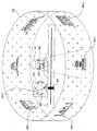
- the thumbnail image may include a first image 420-2 corresponding to a first region 420-1 of the surround video image and a second image 430-2 corresponding to a second region 430-1 of the surround video image. More specifically, the thumbnail image may correspond to an image corresponding to a whole region included in the surround video image. Additionally, as an example, the thumbnail image may correspond to an image corresponding to a part of the surround video image, by which the present specification may be non-limited.
- the HMD device 100 may display the thumbnail image based on time information within the surround video image. More specifically, the thumbnail image may include the time information within the surround video image. In this case, the time information may correspond to information on timing of displaying the thumbnail image in the surround video image. In this case, the HMD device 100 may display the thumbnail image in a position corresponding to the time information of a progress bar 440. Additionally, as an example, the HMD device 100 may display a plurality of thumbnail images. More specifically, the HMD device 100 may display the thumbnail image in a position at which an indicator is positioned in the progress bar 440. Additionally, the HMD device 100 may display a plurality of the thumbnail images based on a prescribed time interval in the progress bar 440, by which the present specification may be non-limited.
- the HMD device 100 may display a first thumbnail image 410-1 of a cylinder form.
- the thumbnail image may include the first image 420-2 corresponding to the first region 420-1 and the second image 430-2 corresponding to the second region 430-1.
- the HMD device 100 may display the thumbnail image adjacent to the indicator 450 of the progress bar 440.
- the indicator 450 may be displayed in a position corresponding to time information within the surround video image.
- the HMD device 100 may display the thumbnail image identical to the surround video image in response to the time information of the surround video image.
- the HMD device 100 may display a second thumbnail image 410-2 of a hemisphere form.
- the thumbnail image may include the first image 420-2 corresponding to the first region 420-1 and the second image 430-2 corresponding to the second region 430-1.
- the HMD device 100 may display a third thumbnail image 410-3 of a sphere form.
- the thumbnail image may include the first image 420-2 corresponding to the first region 420-1 of the surround video image and the second image 430-2 corresponding to the second region 430-1 of the surround video image.
- the HMD device may display the thumbnail image based on the image type of the surround video image.
- the HMD device 100 may display the thumbnail image based on the changed image type.
- FIG. 5a to FIG. 5c are diagrams of a method for an HMD device according to one embodiment of the present specification to display a thumbnail image based on a display attribute of a thumbnail image.
- the HMD device may display a thumbnail image based on a display attribute of the thumbnail image.
- the display attribute may include at least one selected from the group consisting of a shape, a size and a position of the thumbnail image to be displayed. More specifically, the display attribute of the thumbnail image may correspond to a form of the thumbnail image.
- the HMD device 100 may display the thumbnail image related to a surround video image. In this case, the HMD device 100 may display the thumbnail image of the surround video image including an identical image type in various forms.
- the HMD device 100 may display a thumbnail image for a surround video image of a cylinder type.
- the HMD device 100 may display a first thumbnail image 510-1 corresponding to the surround video image reduced by a predetermined ratio.
- the HMD device 100 may have a form identical to the surround video image.
- the HMD device 100 may display a second thumbnail image 510-2, which displays a first image 540 and a second image 550 in a manner of overlapping with each other.
- the first image 540 may correspond to an image corresponding to a first region of the surround video image.
- the second image 550 may correspond to an image corresponding to a second region of the surround video image.
- the first region may correspond to a region displayed in a first direction corresponding to a prescribed direction among directions within a threshold range on the basis of a front direction of a user in the surround video image.
- the second region may correspond to a region displayed in a second direction corresponding to a prescribed direction among directions within the threshold range on the basis of a rear direction of the user in the surround video image.
- the HMD device 100 may determine the front direction and the rear direction of the user based on the aforementioned reference direction.
- the first region may correspond to a region located at the front of a part in which the reference direction is determined on the basis of the HMD device 100 and the second region may correspond to a region located at the rear of the part in which the reference direction is determined on the basis of the HMD device 100.
- the first region may correspond to a part of the surround video image corresponding to time information identical to the second region. More specifically, the HMD device 100 may sequentially display images in response to the time information of the surround video image. In particular, the first region and the second region may correspond to regions which are changed by the front direction of the HMD device 100 only in response to the identical time information.
- the HMD device 100 may display the first image 540 corresponding to the first region and the second image 550 corresponding to the second region in a manner of overlapping the images with each other. In this case, the HMD device 100 may display the second image 550 at the back of the first image 540. Additionally, as an example, in case that the HMD device 100 displays the first image 540 and the second image in a manner of overlapping the images with each other, the HMD device 100 may transparently display the first image 540 which is displayed at the front of the second image 550.
- the HMD device 100 may display a third thumbnail image 510-3 corresponding to a planar figure of the unfolded surround video image. More specifically, the HMD device 100 may display an image, which is reduced from the planar figure of the unfolded surround video image of the cylinder form by a reference ratio, as a thumbnail image.
- the HMD device 100 may display a thumbnail image for a surround video image of a sphere image type.
- the HMD device may display a first thumbnail image 560-1, which is reduced from the surround video image by the reference ratio.
- the HMD device 100 may have a form identical to the surround video image.
- the HMD device 100 may display a second thumbnail image 560-2 corresponding to a planar figure image of the unfolded surround video image.
- the second thumbnail image 560-2 may correspond to an image of the surround video image unfolded to a globe form.
- the HMD device 100 may display a third thumbnail image 560-3 corresponding to a planar figure image of the surround video image unfolded to an icosahedron.
- the thumbnail image may include the first image 540 corresponding to the first region and the second image 550 corresponding to the second region.
- the HMD device 100 may display a thumbnail image for a surround video image of a hemisphere image type.
- the HMD device may display a first thumbnail image 570-1, which is reduced from the surround video image by a predetermined ratio.
- the HMD device 100 may have a form identical to the surround video image.
- the HMD device 100 may display a second thumbnail image 570-2 corresponding to a planar figure image of the unfolded surround video image.
- the second thumbnail image 570-2 may correspond to an image of the surround video image unfolded to a globe form.
- the second thumbnail image may correspond to a planar figure of a hemisphere.
- the HMD device 100 may display a thumbnail image base on a direction of a gaze facing the surround video image.
- the HMD device 100 may display a third thumbnail image 570-3 in a form that the surround video image is seen from the top.
- the third thumbnail image 570-3 may be displayed in a circle shape.
- FIG. 6 is a diagram of a method for an HMD device according to one embodiment of the present specification to change a region displayed in a front direction of the HMD device based on a control input.
- the HMD device 100 detects a control input using the sensor unit 110 and may deliver the detected control input to the processor.
- the control input may correspond to at least one selected from the group consisting of a gesture input, a touch input, an audio input and an input inputted by an input device.
- the control input may correspond to an input for controlling a thumbnail image displayed in the HMD device 100. More specifically, the HMD device 100 detects the control input for the thumbnail image and may control a surround video image corresponding to the thumbnail image based on the detected control input. As an example, referring to FIG. 6, the HMD device 100 may display a surround video image 610-1, a thumbnail image 610-2 and a progress bar 640.
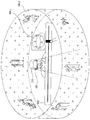
- the HMD device 100 may display a first region 620-1 among the surround video image 610-1. Additionally, the HMD device 100 may display the thumbnail image 610-2 corresponding to the surround video image as a planar figure image. In this case, the thumbnail image 610-2 may include a first image 620-2 corresponding to the first region 620-1 of the surround video image 610-1. Additionally, the thumbnail image 610-2 may include a second image 630-2 corresponding to a second region 630-1 of the surround video image 610-1. Additionally, the HMD device 100 may display the thumbnail image 610-2 adjacent to an indicator 650 indicating time information of the surround video image 610-1 in the progress bar 640.
- the HMD device 100 may detect a control input for selecting the second image 630-2 from the thumbnail image 610-2.
- the HMD device 100 may display the second region 630-1 among the surround video image based on the detected control input.
- the HMD device 100 may display the first region 620-1.
- the HMD device 100 may display the second region 630-1 based on the aforementioned control input instead of the first region 620-1 which is used to be displayed.
- the HMD device 100 may change a displayed region among the surround video image without changing the front direction of the HMD device 100.
- FIG. 7 is a diagram of a method for an HMD device according to one embodiment of the present specification to display a thumbnail image including a main region.
- a thumbnail image 710 may include a main region 720 and a sub region.
- the main region 720 may correspond to a representative region of the thumbnail image 710.
- the HMD device 100 may display an indicator 740 indicating time information in a progress bar 730.
- the HMD device 100 may display the main region most adjacent to the indicator 740 among the thumbnail image 710.
- the HMD device 100 may set up a region at which most of gazes are arriving as the main region among the thumbnail image 710.
- the main region 720 can be determined by a user or the HMD device 100, by which the present specification may be non-limited.
- the HMD device 100 may include a main image.
- the main image may correspond to a representative image of a thumbnail image.
- the main image may correspond to an image corresponding to a displayed region when a front direction of the HMD device 100 corresponds to a direction at which a user is facing among the surround video image. More specifically, the HMD device 100 sets up the aforementioned reference direction and may detect the front direction of the HMD device 100 based on the reference direction. In this case, as an example, the HMD device 100 sets up the front direction of the HMD device on timing that the user wears the HMD device 100 as the reference direction and may set up it as the front direction of the user.
- the HMD device 100 may set up an image corresponding to the region displayed in the front direction of the user as the main image of the thumbnail image among the surround video image. Additionally, as an example, the HMD device 100 may set up an image corresponding to a representative region of the surround video image as the main image. Additionally, the main image can be differently determined by the user or the HMD device 100, by which the present specification may be non-limited.
- the HMD device 100 may display a main image in a main region of the thumbnail image 710.
- the HMD device 100 may display the main image in the main region as a representative image of the surround video image.
- FIG. 8a to FIG. 8c are diagrams of a method for an HMD device according to one embodiment of the present specification to change an image displayed in a main region. If the HMD device 100 detects that a front direction of the HMD device 100 corresponds to a first direction, the HMD device 100 may display a first region. Subsequently, the HMD device 100 may display a thumbnail image 810. In this case, the thumbnail image 810 may include a first image 850-1 corresponding to the first region. Additionally, the HMD device 100 may display the first image 850-1 in a main region of the thumbnail image. In particular, the HMD device 100 may display an image corresponding to a region watched by a user in the main region of the thumbnail image 810.
- the HMD device 100 may detect a control input for rotating the thumbnail image 810 in a state that the first image 850-1 is displayed in the main region of the thumbnail image 810.
- the control input may correspond to a slide touch input or a gesture input, by which the present specification may be non-limited.
- the HMD device 100 may display a second image 840-1 in the main region of the thumbnail image.
- the second image 840-1 may correspond to an image adjacent to the first image 850-1.
- the HMD device 100 may change the image displayed in the main region using the control input in the state that the thumbnail image 810 is displayed.
- the HMD device 100 may change the first image 850-1 displayed in the main region to the second image 840-1.
- the HMD device may rotate the thumbnail image 810. By doing so, the HMD device 100 may change the image displayed in the main region of the thumbnail image 810.
- the HMD device 100 may display the thumbnail image 810, a progress bar 820 and the surround video image at the same time.
- the HMD device 100 may detect a control input for selecting the first image 850-1 of the thumbnail image 810.
- the HMD device 100 may display a first region 850-2 of the surround video image corresponding to the first image 850-1.
- the HMD device 100 may control the surround video image 220 corresponding to the thumbnail image using the thumbnail image 810.
- the HMD device 100 may detect a control input for rotating the thumbnail image 810 in a state that the first image 850-1 is displayed in the main region of the thumbnail image 810.
- the HMD device 100 may display a second image 840-1 in the main region of the thumbnail image.
- the HMD device 100 may display a second region 840-2 of the surround video image corresponding to the second image 840-1.
- the second region 840-2 may correspond to a region adjacent to the first region 850-2.
- FIG. 9a to FIG. 9c are diagrams of a method for an HMD device according to one embodiment of the present specification to display a thumbnail image adjacent to a progress bar based on time information of the thumbnail image.
- the HMD device 100 may display a thumbnail image adjacent to a progress bar.
- the thumbnail image may include time information of a surround video image corresponding to the thumbnail image.
- the HMD device 100 may display the thumbnail image in a position corresponding to the time information adjacent to the progress bar.
- the HMD device 100 may display the thumbnail image adjacent to an indicator indicating the time information.
- the HMD device 100 may display a plurality of thumbnail images, by which the present specification may be non-limited.
- the HMD device 100 may display the surround video image using a control input for selecting the thumbnail image which is displayed in response to the time information.
- the HMD device 100 may display a first thumbnail image 910-1 adjacent to a progress bar 920 as a position corresponding to a first time information.
- the HMD device 100 may display a first surround video image 910-2 related to the first thumbnail image 910-1.
- the HMD device 100 may display a second surround video image 940-2 related to a second thumbnail image 940-1.
- the HMD device 100 may control the thumbnail image and the surround video image using the progress bar 920 and the indicator 930.
- FIG. 10a and FIG. 10b are diagrams of a method for an HMD device according to one embodiment of the present specification to display a thumbnail image based on a progress bar.
- the HMD device 100 may display a thumbnail image adjacent to a progress bar.
- the HMD device 100 may display the thumbnail image based on a shape, a size or a position of the displayed the progress bar 1020. More specifically, the HMD device 100 may change the shape, the size or the position of the displayed progress bar.
- the HMD device 100 may display the progress bar 1020 in a horizontal or a vertical direction. Additionally, as an example, the HMD device 100 may display the progress bar 1020 in three dimensions.
- the HMD device 100 may control a method of displaying the progress bar 1020. In this case, the HMD device 100 may display the thumbnail image based on the progress bar 1020.
- the HMD device 100 displays a part of the thumbnail image adjacent to a first side of the progress bar 1020 and may display a part of the thumbnail image adjacent to a second side of the progress bar 1020. Additionally, as an example, the HMD device 100 displays a main region of the thumbnail image adjacent to the first side of the progress bar 1020 and may display a sub region of the thumbnail image adjacent to the second side of the progress bar.
- the HMD device 100 may display a thumbnail image.
- the HMD device 00 may display a first internal thumbnail image 1010-1 at the top of the progress bar 1020.
- the HMD device 100 may display a second internal thumbnail image 1010-2 at the bottom of the progress bar 1020.
- the HMD device 100 may display the thumbnail image in a manner of dividing the thumbnail image into two on the basis of the progress bar.
- the HMD device 100 may display the progress bar 1020 in a vertical direction. Additionally, as an example, the HMD device 100 may display a thumbnail image 1040 in a manner of making the thumbnail image surround the progress bar 1020. More specifically, the HMD device 100 may display the thumbnail image 1040 of a ring form on the basis of the progress bar 1020. In particular, the HMD device 100 may display the thumbnail image in consideration of the progress bar 1020, by which the present specification may be non-limited.
- FIG. 11a and FIG. 11b are diagrams of a method for an HMD device according to one embodiment of the present specification to control a thumbnail image using a progress bar.
- the HMD device 100 may execute a progress bar interface for controlling a progress bar 1120.
- the progress bar interface may correspond to an interface controlling the progress bar 1120 and a thumbnail image displayed adjacent to the progress bar.
- the progress bar interface may correspond to an interface for changing an image displayed in a main region among thumbnail images.
- the progress bar interface may correspond to an interface controlling whether to display a thumbnail image.
- the progress bar interface may correspond to an interface controlling an indicator 1130 corresponding to time information.
- the progress bar interface may correspond to an interface controlling the displayed progress bar 1120 and the thumbnail image.
- the progress bar interface may correspond to an interface for rotating the progress bar 1120 on the basis of a rotation axis. More specifically, the HMD device 100 may rotate the progress bar 1120 using the progress bar interface. In this case, the HMD device 100 may display a first image 1150-1 in a main region of a first thumbnail image 1110-1. Additionally, the HMD device may display a second image 1150-2 in a main region of a second thumbnail image 1110-2. Subsequently, if the HMD device 100 detects that the progress bar rotates on the basis of the rotation axis of the progress bar 1120, the HMD device 100 may display a third image 1140-1 in the main region of the first thumbnail image 1110-1. Additionally, the HMD device 100 may display a fourth image 1140-2 in the main region of the second thumbnail image 1110-2.
- the HMD device 100 may change the image displayed in the main region of each of a plurality of the thumbnail images using the progress bar interface.
- the HMD device 100 may further display a ring progress bar 1160.
- the ring progress bar 1160 may correspond to an interface for controlling a thumbnail image. More specifically, the HMD device 100 may control an image displayed in a main region of the thumbnail image using the ring progress bar 1160.
- the HMD device 100 may display a first image 1190-1 in a main region of a first thumbnail image 1170-1. Additionally, the HMD device 100 may display a second image 1190-2 in a main region of a second thumbnail image 1170-2.
- the HMD device 100 may display a third image 1180-1 in the main region of the first thumbnail image 1170-1. Additionally, the HMD device 100 may display a fourth image 1180-2 in the main region of the second thumbnail image 1170-2. In particular, the HMD device 100 may change the image displayed in the main region of each of a plurality of the thumbnail images using the ring progress bar 1160.
- FIG. 12 is a flowchart for a method of controlling an HMD device according to one embodiment of the present specification.
- the HMD device may detect a front direction of the HMD device 100 [S1210].
- the front direction of the HMD device 100 is changed based on a movement of a user wearing the HMD device 100 and may be determined on the basis of the HMD device 100. More specifically, the front direction of the HMD device 100 may correspond to a direction at which the user is facing while wearing the HMD device 100. Additionally, the HMD device 100 may set up a reference direction for the front direction of the HMD device 100. The HMD device 100 may detect that the front direction of the HMD device 100 is changing based on the reference direction.
- the HMD device 100 may set up the front direction of the HMD device 100 of when the user displays the surround video image as the reference direction.
- the HMD device 100 may detect that the front direction of the HMD device 100 is changing on the basis of the reference direction.
- the front direction of the HMD device 100 can be detected based on the reference direction.
- the reference direction can be determined by the user or the HMD device 100, by which the present specification may be non-limited.
- the HMD device 100 may display a first region among the surround video image [S1220]. Additionally, if the HMD device 100 detects that the front direction corresponds to a second direction, the HMD device 100 may display a second region among the surround video image [S1230]. As mentioned earlier in FIG. 2a to FIG. 2c, the HMD device 100 may display a part of the surround video image based on the front direction of the HMD device 100.
- the surround image may correspond to an image unfolded to a prescribed direction (e.g., a front, a rear, a left, a right, a top, or a bottom direction) on the basis of the HMD device 100.
- the HMD device 100 detects a direction at which the user is facing as the front direction of the HMD device 100 and may be then able to provide a surround image corresponding to the direction.
- the HMD device 100 may display a part of the surround video image based on the front direction.
- the HMD device 100 may display a progress bar indicating a progress status of the surround video image [S1240].
- the progress bar may indicate the progress status based on time information of the surround video image within surround video content.
- the progress bar may display an indicator in a position corresponding to the time information of the surround video image.
- the progress bar may display the surround video image based on the time information of the point at which the indicator is positioned.
- the progress bar may include information on the progress status of the surround video image.
- the HMD device 100 may display a thumbnail image in a position corresponding to the time information of the surround video image in the progress bar [S1250].
- the thumbnail image may include time information within the surround video image.
- the display unit 120 may display the thumbnail image adjacent to the progress bar as a point corresponding to the time information included in the thumbnail image. Additionally, as an example, the display unit 120 may display the surround video image, the thumbnail image and the progress bar at the same time.
- the HMD device 100 may display a first image corresponding to the first region of the surround video image and a thumbnail image including a second image corresponding to the second region of the surround video image based on a display attribute of the thumbnail image [S1260].
- the HMD device 100 may display a thumbnail image based on a display attribute of the thumbnail image.
- the display attribute may include at least one selected from the group consisting of a shape of the thumbnail image, a size of the thumbnail image and a position in which the thumbnail image is displayed. More specifically, the display attribute of the thumbnail image may correspond to a form of the thumbnail image.
- the HMD device 100 may display a thumbnail image related to the surround video image. In this case, the HMD device 100 may display a thumbnail image of the surround video image including an identical image type in various forms.
- a HMD device 100 according to the present specification and a method of controlling therefor may not limitedly apply to the composition and method of the aforementioned embodiments.
- the aforementioned embodiments may be determined in a manner of being selectively combined the whole of the embodiments or a part of the embodiments to achieve various modifications.
- a HMD device 100 can be implemented with a code readable by a controller in a recording media readable by the controller, which is equipped in the device.
- the recording media readable by the controller may include all kinds of recording devices for storing data capable of being read by the controller.
- the examples of the recording media readable by the controller may include a ROM, a RAM, a magnetic tape, a floppy disc, an optical data storing device and the like.
- implementing in a form of a carrier wave such as a transmission via the internet and the like is also included.
- the recording media readable by the processor are distributed to the computers connected by a network, codes readable by the processor can be stored and executed in a manner of being distributed.
- the present invention is totally or partially applicable to electronic devices.
Landscapes
- Engineering & Computer Science (AREA)
- General Engineering & Computer Science (AREA)
- Theoretical Computer Science (AREA)
- Physics & Mathematics (AREA)
- General Physics & Mathematics (AREA)
- Human Computer Interaction (AREA)
- Optics & Photonics (AREA)
- Controls And Circuits For Display Device (AREA)
Abstract
La présente invention concerne un dispositif de visiocasque et son procédé de commande. Selon un mode de réalisation de la présente invention, un procédé de commande d'un dispositif de visiocasque comprend les étapes consistant à afficher une partie d'une image vidéo environnante, si une direction avant du dispositif de visiocasque correspond à une première direction, à afficher une première région parmi l'image vidéo environnante et, si la direction avant du dispositif de visiocasque correspond à une seconde direction, à afficher une seconde région parmi l'image vidéo environnante, et à afficher une image miniature associée à l'image vidéo environnante et une barre de progression indiquant un état de progression de l'image vidéo environnante, l'image miniature comprenant une première image correspondant à la première région de l'image vidéo environnante et une seconde image correspondant à la seconde région de l'image vidéo environnante.
Applications Claiming Priority (4)
| Application Number | Priority Date | Filing Date | Title |
|---|---|---|---|
| KR1020140048530A KR20150122355A (ko) | 2014-04-23 | 2014-04-23 | 썸네일 이미지를 디스플레이 하는 헤드 마운티드 디스플레이 디바이스 및 그 제어 방법 |
| KR10-2014-0048530 | 2014-04-23 | ||
| US14/289,356 US20150309310A1 (en) | 2014-04-23 | 2014-05-28 | Head mounted display device displaying thumbnail image and method of controlling therefor |
| US14/289,356 | 2014-05-28 |
Publications (1)
| Publication Number | Publication Date |
|---|---|
| WO2015163529A1 true WO2015163529A1 (fr) | 2015-10-29 |
Family
ID=54332676
Family Applications (1)
| Application Number | Title | Priority Date | Filing Date |
|---|---|---|---|
| PCT/KR2014/005076 Ceased WO2015163529A1 (fr) | 2014-04-23 | 2014-06-10 | Dispositif de visiocasque pour l'affichage d'image miniature et son procédé de commande |
Country Status (1)
| Country | Link |
|---|---|
| WO (1) | WO2015163529A1 (fr) |
Cited By (5)
| Publication number | Priority date | Publication date | Assignee | Title |
|---|---|---|---|---|
| CN105653034A (zh) * | 2015-12-31 | 2016-06-08 | 北京小鸟看看科技有限公司 | 一种三维沉浸式环境下内容切换方法和装置 |
| CN105677165A (zh) * | 2015-12-31 | 2016-06-15 | 北京小鸟看看科技有限公司 | 一种三维沉浸式环境下列表切换方法和装置 |
| WO2018080165A1 (fr) * | 2016-10-28 | 2018-05-03 | Samsung Electronics Co., Ltd. | Appareil d'affichage d'image, dispositif mobile et procédé de fonctionnement associé |
| US10372289B2 (en) | 2015-12-31 | 2019-08-06 | Beijing Pico Technology Co., Ltd. | Wraparound interface layout method, content switching method under three-dimensional immersive environment, and list switching method |
| EP3319308B1 (fr) * | 2016-10-27 | 2022-08-03 | Samsung Electronics Co., Ltd. | Appareil d'affichage d'un image spherique et procédés pour l'affichage d'un image sur un ecran planar |
Citations (5)
| Publication number | Priority date | Publication date | Assignee | Title |
|---|---|---|---|---|
| US20040179104A1 (en) * | 2003-03-10 | 2004-09-16 | Charles Benton | Augmented reality navigation system |
| JP2012008290A (ja) * | 2010-06-23 | 2012-01-12 | Softbank Mobile Corp | 眼鏡型表示装置及びサーバ |
| US20130222638A1 (en) * | 2012-02-29 | 2013-08-29 | Google Inc. | Image Capture Based on Gaze Detection |
| US20130257709A1 (en) * | 2012-04-02 | 2013-10-03 | Google Inc. | Proximity Sensing for Wink Detection |
| KR20140010715A (ko) * | 2012-07-16 | 2014-01-27 | 엘지전자 주식회사 | 헤드 마운트 디스플레이를 이용한 컨텐츠 출력 방법 및 이를 위한 헤드 마운트 디스플레이 |
-
2014
- 2014-06-10 WO PCT/KR2014/005076 patent/WO2015163529A1/fr not_active Ceased
Patent Citations (5)
| Publication number | Priority date | Publication date | Assignee | Title |
|---|---|---|---|---|
| US20040179104A1 (en) * | 2003-03-10 | 2004-09-16 | Charles Benton | Augmented reality navigation system |
| JP2012008290A (ja) * | 2010-06-23 | 2012-01-12 | Softbank Mobile Corp | 眼鏡型表示装置及びサーバ |
| US20130222638A1 (en) * | 2012-02-29 | 2013-08-29 | Google Inc. | Image Capture Based on Gaze Detection |
| US20130257709A1 (en) * | 2012-04-02 | 2013-10-03 | Google Inc. | Proximity Sensing for Wink Detection |
| KR20140010715A (ko) * | 2012-07-16 | 2014-01-27 | 엘지전자 주식회사 | 헤드 마운트 디스플레이를 이용한 컨텐츠 출력 방법 및 이를 위한 헤드 마운트 디스플레이 |
Cited By (6)
| Publication number | Priority date | Publication date | Assignee | Title |
|---|---|---|---|---|
| CN105653034A (zh) * | 2015-12-31 | 2016-06-08 | 北京小鸟看看科技有限公司 | 一种三维沉浸式环境下内容切换方法和装置 |
| CN105677165A (zh) * | 2015-12-31 | 2016-06-15 | 北京小鸟看看科技有限公司 | 一种三维沉浸式环境下列表切换方法和装置 |
| US10372289B2 (en) | 2015-12-31 | 2019-08-06 | Beijing Pico Technology Co., Ltd. | Wraparound interface layout method, content switching method under three-dimensional immersive environment, and list switching method |
| EP3319308B1 (fr) * | 2016-10-27 | 2022-08-03 | Samsung Electronics Co., Ltd. | Appareil d'affichage d'un image spherique et procédés pour l'affichage d'un image sur un ecran planar |
| WO2018080165A1 (fr) * | 2016-10-28 | 2018-05-03 | Samsung Electronics Co., Ltd. | Appareil d'affichage d'image, dispositif mobile et procédé de fonctionnement associé |
| US10810789B2 (en) | 2016-10-28 | 2020-10-20 | Samsung Electronics Co., Ltd. | Image display apparatus, mobile device, and methods of operating the same |
Similar Documents
| Publication | Publication Date | Title |
|---|---|---|
| WO2015178535A1 (fr) | Dispositif pouvant être porté affichant une image miniature et son procédé de commande | |
| WO2015030303A1 (fr) | Dispositif portatif affichant une image de réalité augmentée et son procédé de commande | |
| WO2015005537A1 (fr) | Dispositif mobile, afficheur de tête et procédé de commande associé | |
| WO2015163529A1 (fr) | Dispositif de visiocasque pour l'affichage d'image miniature et son procédé de commande | |
| WO2015111790A1 (fr) | Montre intelligente, dispositif d'affichage et son procédé de commande | |
| WO2020262923A1 (fr) | Système et procédé permettant de générer une expérience de réalité mixte | |
| WO2015122565A1 (fr) | Système d'affichage permettant d'afficher une imagé de réalité augmentée et son procédé de commande | |
| WO2015030304A1 (fr) | Dispositif portable prenant en charge la vidéotéléphonie avec des lunettes de visualisation et procédé de commande associé | |
| WO2015030305A1 (fr) | Dispositif portable affichant une image de réalité augmentée et procédé de commande pour celui-ci | |
| WO2015163536A1 (fr) | Dispositif d'affichage et son procédé de commande | |
| EP2939062A1 (fr) | Affichage porté sur la tête et procédé de communication vidéo utilisant ledit affichage | |
| WO2020080740A1 (fr) | Dispositif électronique comprenant une couche tactile ayant une ouverture | |
| EP3042266A1 (fr) | Dispositif portatif et procédé de commande associé | |
| WO2015046686A1 (fr) | Dispositif d'affichage pouvant être porté et procédé permettant de commander une couche dans celui | |
| WO2014157806A1 (fr) | Dispositif d'affichage et son procédé de commande | |
| WO2016021965A1 (fr) | Dispositif électronique et procédé de commande de l'affichage de celui-ci | |
| WO2015190647A1 (fr) | Dispositif d'affichage exécutant une fonction de flexion et son procédé de commande | |
| WO2014171580A1 (fr) | Dispositif numérique et son procédé de commande | |
| EP3134764A1 (fr) | Visiocasque et son procédé de commande | |
| WO2013133618A1 (fr) | Procédé pour commander au moins une fonction d'un dispositif par action de l'œil et dispositif pour exécuter le procédé | |
| WO2016072785A1 (fr) | Dispositif électronique basé sur la direction pour afficher un objet et procédé associé | |
| WO2015030308A1 (fr) | Dispositif numérique et procédé de commande associé | |
| WO2016088922A1 (fr) | Procédé de fourniture d'interface faisant appel à un dispositif mobile et dispositif portable | |
| WO2023090650A1 (fr) | Dispositif permettant de dispenser une leçon de golf | |
| WO2019098609A1 (fr) | Procédé et appareil de gestion de contenu à vue large dans un environnement de réalité virtuelle |
Legal Events
| Date | Code | Title | Description |
|---|---|---|---|
| 121 | Ep: the epo has been informed by wipo that ep was designated in this application |
Ref document number: 14889866 Country of ref document: EP Kind code of ref document: A1 |
|
| NENP | Non-entry into the national phase |
Ref country code: DE |
|
| 122 | Ep: pct application non-entry in european phase |
Ref document number: 14889866 Country of ref document: EP Kind code of ref document: A1 |