WO2015166642A1 - 衛生洗浄装置 - Google Patents
衛生洗浄装置 Download PDFInfo
- Publication number
- WO2015166642A1 WO2015166642A1 PCT/JP2015/002136 JP2015002136W WO2015166642A1 WO 2015166642 A1 WO2015166642 A1 WO 2015166642A1 JP 2015002136 W JP2015002136 W JP 2015002136W WO 2015166642 A1 WO2015166642 A1 WO 2015166642A1
- Authority
- WO
- WIPO (PCT)
- Prior art keywords
- water
- unit
- sanitary washing
- electrode
- sterilization
- Prior art date
- Legal status (The legal status is an assumption and is not a legal conclusion. Google has not performed a legal analysis and makes no representation as to the accuracy of the status listed.)
- Ceased
Links
Images


Classifications
-
- E—FIXED CONSTRUCTIONS
- E03—WATER SUPPLY; SEWERAGE
- E03D—WATER-CLOSETS OR URINALS WITH FLUSHING DEVICES; FLUSHING VALVES THEREFOR
- E03D9/00—Sanitary or other accessories for lavatories ; Devices for cleaning or disinfecting the toilet room or the toilet bowl; Devices for eliminating smells
- E03D9/08—Devices in the bowl producing upwardly-directed sprays; Modifications of the bowl for use with such devices ; Bidets; Combinations of bowls with urinals or bidets; Hot-air or other devices mounted in or on the bowl, urinal or bidet for cleaning or disinfecting
-
- E—FIXED CONSTRUCTIONS
- E03—WATER SUPPLY; SEWERAGE
- E03C—DOMESTIC PLUMBING INSTALLATIONS FOR FRESH WATER OR WASTE WATER; SINKS
- E03C1/00—Domestic plumbing installations for fresh water or waste water; Sinks
- E03C1/02—Plumbing installations for fresh water
- E03C1/04—Water-basin installations specially adapted to wash-basins or baths
- E03C1/046—Adding soap, disinfectant, or the like in the supply line or at the water outlet
-
- E—FIXED CONSTRUCTIONS
- E03—WATER SUPPLY; SEWERAGE
- E03C—DOMESTIC PLUMBING INSTALLATIONS FOR FRESH WATER OR WASTE WATER; SINKS
- E03C2201/00—Details, devices or methods not otherwise provided for
- E03C2201/40—Arrangement of water treatment devices in domestic plumbing installations
Definitions
- the present invention relates to a sanitary washing device for washing a human body.
- a warm water washing toilet seat has a sanitary washing device that ejects hot water from a nozzle device toward a local area.
- the nozzle device is configured such that, during cleaning, the nozzle portion approaches a local part of the human body and jets cleaning water.
- the sanitary washing apparatus having the above-described configuration tends to be exposed to dirt or sewage on the nozzle portion during washing. Therefore, a sanitary washing device configured to wash the nozzle portion has been proposed (see, for example, Patent Document 1).
- the sanitary washing apparatus described in Patent Document 1 has a configuration in which a liquid agent is injected into a washing water and sprayed when the nozzle portion is washed. Then, the nozzle portion is cleaned by splashing the cleaning water or exposing it to the cleaning water. Thereby, the stain
- the conventional sanitary washing device configuration cannot sterilize washing water or bacteria that have propagated in the washing water flow path to the nozzle. That is, the local part is washed with washing water containing bacteria. Therefore, there was a problem in terms of hygiene.
- the present invention provides a sanitary washing apparatus capable of sterilizing the washing water and the inside of the washing water flow path to the nozzle.
- the sanitary washing device of the present invention includes a nozzle that moves to a predetermined washing position and ejects washing water, a washing water passage that guides washing water to the nozzle, a pump that discharges washing water from the nozzle, and washing water.
- a heating unit for heating Furthermore, it is provided on the upstream side of the heating unit, and includes a sterilizing unit that sterilizes the cleaning water, and a control unit that controls the pump, the heating unit, and the sterilizing unit.
- the sterilization unit can sterilize the washing water and the bacteria present in the washing water flow path.
- cleans a local part with a clean washing water is realizable.
- FIG. 1 is a perspective view of a toilet apparatus equipped with a sanitary washing device according to Embodiment 1 of the present invention.
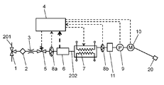
- FIG. 2 is a schematic diagram showing a configuration of a supply system of cleaning water to the nozzle of the main body of the sanitary cleaning device in the same embodiment.
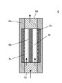
- FIG. 3 is a cross-sectional view showing a configuration of a sterilization unit of the sanitary washing device according to the embodiment.
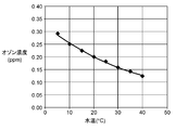
- FIG. 4 is a graph showing the relationship between the water temperature of the sterilization unit and the ozone concentration in the same embodiment.
- FIG. 5 is a schematic diagram showing the configuration of the main body of the sanitary washing device according to Embodiment 2 of the present invention.
- FIG. 1 is a perspective view of a toilet apparatus equipped with a sanitary washing device according to Embodiment 1 of the present invention.
- FIG. 2 is a schematic diagram showing a configuration of a supply system of cleaning water to the nozzle of the main body of the sanitary cleaning device in the same embodiment.
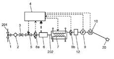
- FIG. 6 is a schematic diagram showing the configuration of the main body of the sanitary washing device according to Embodiment 3 of the present invention.
- FIG. 7 is a schematic diagram showing the configuration of the main body of the sanitary washing device according to Embodiment 4 of the present invention.
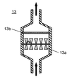
- FIG. 8A is a cross-sectional view showing a scale pulverizing portion in the same embodiment.
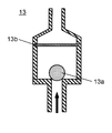
- FIG. 8B is a cross-sectional view showing another example of the scale crushing portion in the same embodiment.
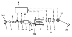
- FIG. 9 is a schematic diagram showing the configuration of the main body of the sanitary washing device according to Embodiment 5 of the present invention.
- Embodiment 1 a sanitary washing device and a toilet device including the same according to Embodiment 1 of the present invention will be described with reference to FIG.
- FIG. 1 is a perspective view of a toilet apparatus equipped with a sanitary washing device according to Embodiment 1 of the present invention.
- a toilet apparatus 1000 includes at least a toilet 600 and a sanitary washing apparatus 100 mounted on the toilet 600.
- the toilet apparatus 1000 is installed in the toilet room.
- the sanitary washing device 100 includes at least a main body 200, an operation device 300, a toilet seat 400, a lid 500, and the like.
- the main body 200 incorporates a cleaning water supply mechanism controlled by the control unit 4 (see FIG. 2).
- the toilet seat 400 and the lid 500 are attached to the main body 200 so as to be freely opened and closed.
- the cleaning water supply mechanism built in the main body 200 supplies the cleaning water supplied from the water pipe to the nozzle 20.
- the nozzle 20 ejects the supplied wash water toward the user's local area. This cleans the local area.
- the toilet apparatus 1000 As described above, the toilet apparatus 1000 according to the present embodiment is configured.
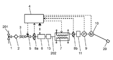
- FIG. 2 is a schematic diagram showing a configuration of a supply system of cleaning water to the nozzle of the main body of the sanitary cleaning device in the same embodiment.
- a cleaning water flow path 202 of the main body 200 that reaches the nozzle 20 via the branch tap 1 is connected to a water supply pipe 201 that is a supply source of cleaning water.
- a strainer 2 In the washing water flow path 202, a strainer 2, a constant flow valve 3, a solenoid valve 5, a sterilization unit 6, a temperature sensor 8 a, a heat exchanger 7, a temperature sensor 8 b, and a positive displacement pump 9 are connected from the branch tap 1 to the nozzle 20. It is inserted in order.
- the nozzle 20 includes a motor 10 that drives the nozzle 20 to move it in and out of a predetermined position.
- tap water flowing through the water pipe 201 is supplied to the strainer 2 as washing water through the branch tap 1.
- the strainer 2 removes dust and impurities contained in the cleaning water.
- the control unit 4 controls the electromagnetic valve 5 to switch the supply state of the cleaning water and supply it to the cleaning water channel 202.
- the cleaning water flowing in the cleaning water flow path 202 passes through the constant flow valve 3 and is depressurized.
- the constant flow valve 3 is composed of, for example, a variable orifice made of rubber or the like whose orifice diameter changes depending on the working water pressure.
- control unit 4 detects the temperature of the cleaning water flowing in the cleaning water flow path 202 with the temperature sensor 8a. And the sterilization part 6 is controlled based on the temperature detected with the temperature sensor 8a. The sterilizing unit 6 generates ozone water from the cleaning water flowing in the cleaning water flow path 202.
- the wash water that has passed through the sterilization unit 6 is supplied to a heat exchanger 7 having a heater provided downstream of the sterilization unit 6 and upstream of the positive displacement pump 9.
- the heater of the heat exchanger 7 heats the supplied cleaning water to a predetermined temperature (for example, 39 ° C.).
- the control unit 4 drives the positive displacement pump 9 connected to the heat exchanger 7. As a result, cleaning water having a flow rate corresponding to the operating speed of the positive displacement pump 9 is discharged from the nozzle 20. And the user's local part is washed. At this time, the control unit 4 controls the heating operation of the heater of the heat exchanger 7 based on the temperature of the cleaning water measured by the temperature sensors 8 a and 8 b and the flow rate of the cleaning water controlled by the positive displacement pump 9. In this embodiment, a pulsation pump is used as the positive displacement pump 9.
- each component of the sanitary washing device is controlled, and washing water flows.
- FIG. 3 is a cross-sectional view showing a configuration of a sterilization unit of the sanitary washing device according to the embodiment.
- the sterilizing unit 6 includes an electrolytic cell 6a, an anode electrode 6b, and a cathode electrode 6c.
- the anode electrode 6b and the cathode electrode 6c are disposed in the axial direction of the electrolytic cell 6a.
- the anode electrode 6b is disposed at the center of the electrolytic cell 6a
- the cathode electrode 6c is disposed on both inner surfaces of the electrolytic cell 6a.
- an electrolytic flow path 6f for the washing water is formed between the anode electrode 6b and the cathode electrode 6c. Then, the washing water flows in from the inlet 6d of the electrolytic cell 6a, flows out of the outlet 6e of the electrolytic cell 6a through the electrolytic channel 6f.
- the sterilization unit 6 electrolyzes the washing water in the electrolytic flow path 6f to efficiently generate ozone water. Then, when bacteria pass through the electrolytic channel 6f, they come into contact with ozone water generated by electrolysis. This makes it possible to sterilize the bacteria.
- the sterilization section of the sanitary washing device is configured.
- anode electrode 6b and the cathode electrode 6c constituting the sterilization part of the sanitary washing apparatus will be specifically described.
- the anode electrode 6b and the cathode electrode 6c are formed by attaching an electrode catalyst to the surface of the metal substrate.
- an electrode catalyst for example, titanium (Ti) with a thickness of 0.5 mm to 1 mm is used as the metal substrate.
- the anode electrode 6b was formed by adhering an electrode catalyst made of, for example, a tantalum oxide (TaOx) layer of about 1000 nm to the surface of the metal substrate.
- the cathode electrode 6c was formed by adhering an electrode catalyst made of, for example, a 1000 nm platinum (Pt) layer or an alloy layer of platinum (Pt) and iridium (Ir) to the surface of the metal substrate.
- an electrode catalyst made of, for example, a 1000 nm platinum (Pt) layer or an alloy layer of platinum (Pt) and iridium (Ir) to the surface of the metal substrate.
- a noble metal or a noble metal oxide may be included as an electrode catalyst.
- anode electrode 6b for example, when platinum is used as a noble metal, first, for example, a solvent adjusted so that the mixing ratio of isopropyl alcohol and ethylene glycol monoethyl ether is 4: 1 is prepared. Then, hexachloroplatinic acid hexahydrate and tantalum ethoxide are dissolved in the prepared solvent so that the total concentration of platinum and tantalum is 1.45 mol / l (mol / liter). In this case, as will be described later, the mixing ratio of platinum and tantalum is such that the tantalum content is 75 mol% or more and the remaining part is platinum in the constituent ratio of tantalum oxide and platinum inside the electrode catalyst. Thereby, a preferable electrode for generating ozone can be formed.
- the anode electrode 6b is prepared by applying a tantalum oxide electrode catalyst having a thickness of 1 nm to several hundreds of nm to the surface of a metal substrate a plurality of times and firing it.
- the thickness of the electrode catalyst of the anode electrode 6b is preferably 500 nm or more, for example. This improves the membrane performance of the electrode catalyst and the adhesion strength between the membranes. Furthermore, the electrode life of the anode electrode 6b and the generation efficiency of ozone are improved.
- the anode electrode 6b is formed by applying an electrode catalyst made of tantalum oxide of 30 nm on the surface of the metal substrate 25 times and baking it.
- the firing temperature is preferably 300 to 700 ° C.
- the adhesiveness between the metal substrate and the electrode catalyst is improved, and a dense electrode catalyst can be formed.
- the anode electrode 6b is manufactured by baking at a baking temperature of 600 ° C. and forming a tantalum oxide electrode catalyst on a metal substrate.
- the surface of the metal substrate is subjected to, for example, blasting or etching to roughen the surface and make it rough.
- an electrode catalyst enters into the uneven part which is the rough surface formed in the surface of a metal substrate.
- the metal substrate preferably has a surface roughness Ra of 1.5 or more.
- the adhesion between the metal substrate and the electrode catalyst is further improved as compared with the surface roughness Ra1.5.
- the time required for the electrode catalyst to peel from the metal substrate can be improved by about 1.5 times. Therefore, in the present embodiment, the metal substrate is immersed in, for example, hot oxalic acid at 100 ° C. for 3 hours to etch the surface.
- titanium (Ti) is used as a metal substrate, and the surface is roughened by etching with hot oxalic acid to form a rough surface.
- platinum serving as a metal layer was applied to the surface of the metal substrate in several times and baked to form a metal layer.
- tantalum oxide as an electrode catalyst was applied in several portions on the metal layer (surface) made of platinum and fired to form an electrode catalyst film.
- the anode electrode 6b was produced by the above method. This makes it possible to extend the time until pitting corrosion occurs on the metal substrate by about 40%.
- the metal layer may be iridium (Ir), ruthenium (Ru), or niobium (Nb) other than platinum, and the same effect can be obtained.
- the anode electrode 6b is formed by forming tantalum oxide as an electrode catalyst on the surface of a metal substrate using titanium.
- the anode electrode 6b can generate substantially the same amount of ozone in an area of, for example, 1 ⁇ 4 compared to an electrode having another configuration (for example, a platinum electrode). As a result, it is possible to reduce the size and cost of the electrode and the electrolytic cell.
- a thin depletion layer is formed at the interface between the surface of tantalum oxide, which is an electrode catalyst, and the washing water.
- the electrons generated by the reaction of the anode electrode 6b pass through the depletion layer formed on the tantalum oxide surface by the tunnel effect.
- the potential at which electrons are transferred is equal to or higher than the oxidation-reduction potential of ozone.
- it is considered that the ozone generation reaction is performed more efficiently and ozone water can be generated.
- an electrode catalyst for generating ozone water for example, lead dioxide, diamond, platinum or the like has been used.
- lead in the case of lead, there are concerns about the impact on the environment and the human body.
- diamond or platinum there are problems such as high cost and low generation efficiency of ozone water. Therefore, it has been difficult to apply conventional electrode catalysts to a wide range of applications and generate ozone water.
- tantalum oxide is used as the electrode catalyst. Tantalum oxide can generate ozone at a lower current density than conventional platinum. Further, tantalum oxide has a feature that ozone generation efficiency increases as the current density decreases.
- tantalum oxide has a high oxygen overvoltage. Therefore, it is possible to generate ozone at a voltage exceeding about 1.5 V, for example, without generating oxygen at a low voltage. Thereby, compared with conventional platinum, tantalum oxide can generate ozone with a power of about 1/4. As a result, when applied to home appliances, energy savings can be further improved.
- ozone water can be generated efficiently by using tantalum oxide for the electrode catalyst.
- CT value is used as one index of sterilization performance.
- C is the concentration (ppm) and T is the time (minutes). That is, the CT value is the product of the concentration C of active species necessary for sterilization or sterilization and the contact time T between the bacteria. That is, the smaller the CT value, the higher the sterilization performance.
- the CT value indicating the sterilization performance of ozone water generated in the present embodiment is about one digit or more smaller than that of hypochlorous acid water, and thus has high reactivity. Therefore, ozone water can be sterilized instantaneously (for a short time) at a low concentration, which was difficult with hypochlorous acid water. That is, the ozone water can be sterilized before the washing water containing the bacteria flows into the electrolytic bath 6 a of the sterilization unit 6 and is discharged from the nozzle 20. Further, the cleaning water flow path 202 can be kept clean with ozone water.
- hypochlorous acid water when hypochlorous acid water is generated by electrolysis, the washing water needs to contain chlorine ions. Furthermore, the amount of hypochlorous acid produced differs depending on the amount of chlorine ions contained in the washing water. In other words, the sterilization performance varies depending on the region. Therefore, when the amount of chlorine ions contained in the washing water is extremely small, it is necessary to supply chlorine ions.
- an electrode catalyst made of tantalum oxide is formed on the surface of the anode electrode 6b. The electrode catalyst of the anode electrode 6b efficiently generates ozone water by the mechanism described above. Therefore, it is not affected by water quality (chlorine ion amount, etc.) depending on the region. As a result, the sterilization unit 6 can always obtain stable sterilization performance.
- the sanitary washing device of the present embodiment is configured such that the sterilization unit 6 having the electrolytic cell 6 a is installed on the upstream side of the heat exchanger 7. The reason for this is to prevent the generation efficiency of ozone water from changing depending on the temperature of the wash water.
- FIG. 4 is a graph showing the relationship between the water temperature of the sterilization unit and the ozone concentration in the same embodiment.
- the sterilization unit 6 having the electrolytic cell 6a is installed on the upstream side of the heat exchanger 7, and the low-temperature washing water before being heated by the heat exchanger 7 is electrolyzed.
- the sterilization unit 6 having the electrolytic cell 6a is installed on the upstream side of the heat exchanger 7, and the low-temperature washing water before being heated by the heat exchanger 7 is electrolyzed.
- ozone water generated from low-temperature washing water can be heated by the heater of the heat exchanger 7. Thereby, the activity and reactivity of ozone can be raised. As a result, the sterilization performance is greatly improved.
- the heater of the heat exchanger 7 is turned on, the water discharged from the electrolytic cell 6a is raised to 39 ° C., and the sterilization rate of the water discharged from the nozzle is increased. evaluated.
- the eradication rate of E. coli was 99.99% or more, and at most 0.01% of E. coli remained.
- the ozone reactivity is improved by heating the generated ozone water with the heat exchanger 7.
- the non-bacteria removal rate is improved by about two orders of magnitude from about 1% to 0.01% or less.
- the sterilization performance can be greatly improved.
- the sanitary washing device of the present embodiment detects the washing water before flowing into the electrolytic cell 6a which is the sterilization unit 6 by the temperature sensor 8a. Based on the detected temperature of the cleaning water, the control unit 4 is configured to control the voltage or current applied to the electrode during the electrolysis of the cleaning water. With this configuration, a change in ozone concentration due to a change in the temperature of the washing water entering the electrolytic cell 6a is suppressed. As a result, it is possible to generate cleaning water having a stable ozone concentration without being affected by the temperature of the cleaning water.
- the control unit 4 lowers the electrolysis voltage to lower the ozone concentration in the washing water.
- the control part 4 raises the voltage of electrolysis and controls so that the ozone concentration in washing water rises. Thereby, it is possible to always ensure a stable ozone concentration without depending on changes in the water temperature. As a result, stable sterilization performance can be obtained.
- the sanitary washing device of the present embodiment is configured such that the end portions of the anode electrode 6b and the cathode electrode 6c are not exposed by being coated by a coating process. Thereby, the electrode life of the anode electrode 6b and the cathode electrode 6c is further improved.
- the coating process suppresses current concentration at the ends of the anode electrode 6b and the cathode electrode 6c during electrolysis. Furthermore, peeling of the electrode catalyst attached to the metal substrate of the anode electrode 6b and the cathode electrode 6c from the metal substrate is suppressed.
- the electrode catalyst attached to the metal substrate of the anode electrode 6b and the cathode electrode 6c is peeled off from the end of the electrode due to physical action such as impact when punching the electrode or influence of water flow by washing water during electrolysis. It's easy to do. Therefore, the electrode end is covered and protected with a coating treatment or a seal. Thereby, exposure of the metal substrate of the anode electrode 6b and the cathode electrode 6c can be prevented. At the same time, peeling of the electrode catalyst from the metal substrate of the anode electrode 6b and the cathode electrode 6c can be effectively suppressed.
- the ends of the anode electrode 6b and the cathode electrode 6c are coated with, for example, UV resin. This makes it possible to extend the time until the pitting corrosion occurs on the metal substrates of the anode electrode 6b and the cathode electrode 6c by about 30%.
- the present invention is not limited to this.
- a glass paste may be applied and baked or coated with a tape, a resin, or the like. Thereby, the same effect is acquired.
- the current value applied between the anode electrode 6b and the cathode electrode 6c may be controlled.
- a control method in which a low current is applied between the anode electrode 6b and the cathode electrode 6c from the initial stage when the electrode catalyst is formed is generally used.
- the electrode catalyst made of tantalum oxide has high activity in the initial stage of formation. Therefore, the ozone concentration in the wash water generated by the electrode catalyst during the initial energization is higher than the ozone concentration after 100 hours of energization.
- the current applied between the anode electrode 6b and the cathode electrode 6c applied to the electrode catalyst in the initial stage of formation is reduced below a specified value. And it controls so that the electric current to apply may be increased with the elapsed time of electrolysis. Thereby, the damage by the electric current applied to the electrode catalyst in the formation initial stage can be suppressed. Furthermore, it is possible to supply cleaning water containing a stable ozone concentration over a long period of time by suppressing a decrease in ozone concentration in the cleaning water with respect to the initial stage.
- the sanitary washing device of the present embodiment is controlled so that the applied current density from the initial formation of the electrode catalyst to 100 h is 10 mA / cm 2 and the applied current density after 100 h is 15 mA / cm 2.
- the applied current is controlled to increase stepwise with the elapsed time of electrolysis.
- generated can be kept constant over a long period of time.
- the electrode lifetime of the anode electrode 6b and the cathode electrode 6c could be improved by about 20%.
- the applied current (applied current density) may be controlled to gradually increase with time. Thereby, the ozone concentration in the cleaning water can be kept more uniform.
- an organic substance removing unit that removes organic substances or the like may be provided on the upstream side of the electrolytic cell 6a that is the sterilizing unit 6 of the washing water flow path 202.
- disinfection performance such as bacteria contained in washing water, improves further.
- an activated carbon filter or the like is provided as an organic substance removing unit.
- the activated carbon filter adsorbs organic substances contained in the cleaning water.
- the washing water from which the organic matter has been removed is electrolyzed in the electrolytic bath 6a of the sterilization unit 6.
- consumption (decrease) of the ozone contained in the wash water by organic substance can be suppressed.
- the ozone concentration contained in the wash water can be maintained more stably, and the sterilization performance can be maintained at a predetermined level over a long period of time.
- the example using ozone as the active species has been described.
- the present invention is not limited to this.
- chlorine or other active species for example, hydrogen peroxide, OH radical, etc.
- the active species is chlorine
- the problem of variation in chlorine ion concentration by region occurs.
- the organic substance removing unit described above it is possible to reduce the amount of hypochlorous acid used in addition to sterilization. At this time, since the activated carbon of the organic substance removing unit does not remove chloride ions, the sterilization rate can be improved.
- the polarity of the current applied to the anode electrode 6b and the cathode electrode 6c is reversed, and the cleaning water is electrolyzed. Thereby, it is suppressed that a scale component adheres to the cathode electrode 6c.
- the cathode electrode 6c electrically attracts cations such as calcium and magnesium contained in the washing water.
- the surface of the cathode electrode 6c becomes alkaline. Therefore, calcium and magnesium in the washing water are deposited on the surface of the cathode electrode 6c as calcium hydroxide or calcium hydroxide. Or calcium and magnesium adhere to the surface of the cathode electrode 6c as calcium carbonate or magnesium carbonate by reaction with carbonate ion.
- the polarity of the current applied to the anode electrode 6b and the cathode electrode 6c is reversed, and the washing water is electrolyzed.
- attachment etc. of scale components such as calcium hydroxide produced
- the scale component adhering to the surface of the cathode electrode 6c can be removed. Specifically, the pH in the vicinity of the electrode becomes strongly acidic due to the inversion of the electrode. Therefore, the scale can be removed from the electrode surface by dissolving the scale deposited on the electrode surface or by peeling it off from the electrode interface.
- Embodiment 2 a sanitary washing device and a toilet device including the same according to Embodiment 2 of the present invention will be described with reference to FIG.
- a toilet apparatus is the same as that of Embodiment 1, description is abbreviate
- FIG. 5 is a schematic diagram showing the configuration of the main body of the sanitary washing device according to Embodiment 2 of the present invention.
- the sanitary washing device according to the present embodiment is implemented in that a storage unit 11 is provided on the downstream side of the electrolytic cell 6 a constituting the sterilization unit 6 and further on the downstream side of the heat exchanger 7.
- a storage unit 11 is provided on the downstream side of the electrolytic cell 6 a constituting the sterilization unit 6 and further on the downstream side of the heat exchanger 7.
- Other configurations and operations are the same as those in the first embodiment. Further, the same components as those in the first embodiment are denoted by the same reference numerals, and description thereof is omitted.
- the storage part 11 of this Embodiment is provided in order to ensure the contact time of active species, such as ozone water produced
- the sterilization performance of the ozone water generated by the sterilization unit 6 can generally be determined by the CT value.
- the CT value of Escherichia coli for ozone water is 0.02
- the concentration of ozone water is 0.02 ppm
- the time required to sterilize Escherichia coli is 1 minute.
- the contact time T with the bacteria may be 1/10 minutes. That is, if bacteria and 0.2 ppm active species are brought into contact for 6 seconds, it means that sterilization is possible.
- the storage unit 11 is provided on the downstream side of the electrolytic cell 6a. Therefore, in the storage part 11, the contact time of an active species and microbe becomes long. As a result, the sterilization performance is further improved.
- the contact time between the active species and the bacteria can be extended, the ozone concentration in the generated wash water can be reduced.
- the electrode lifetime of the anode electrode 6b and the cathode electrode 6c can be extended.
- the voltage or current applied by electrolysis can be reduced. As a result, the sterilization performance can be maintained over a long period of time and the energy saving performance can be improved.
- the configuration in which the storage unit 11 is particularly provided on the downstream side of the heat exchanger 7 has been described as an example, but the present invention is not limited thereto.
- Embodiment 3 a sanitary washing device and a toilet device including the same according to Embodiment 3 of the present invention will be described with reference to FIG.
- a toilet apparatus is the same as that of Embodiment 1, description is abbreviate
- FIG. 6 is a schematic diagram showing the configuration of the main body of the sanitary washing device according to Embodiment 3 of the present invention.
- the sanitary washing device of the present embodiment is provided with an active species removing unit 12 on the downstream side of the electrolytic cell 6 a constituting the sterilizing unit 6 and on the upstream side of the positive displacement pump 9.
- an active species removing unit 12 on the downstream side of the electrolytic cell 6 a constituting the sterilizing unit 6 and on the upstream side of the positive displacement pump 9.
- the active species removing unit 12 of the present embodiment is provided for removing or decomposing active species such as ozone water generated in the electrolytic cell 6a.
- control unit 4 of the sanitary washing apparatus controls the generation amount of active species such as ozone with current and voltage so that the concentration of the generated active species is several ppm or less that does not affect the human body. I have to.
- an active species removing unit 12 made of, for example, an activated carbon filter is provided on the downstream side of the electrolytic cell 6a and the upstream side of the nozzle 20.
- the active species having a concentration higher than the specified value are removed or decomposed.
- the active species concentration discharged from the nozzle 20 is about 1/10 or less of the active species concentration immediately after leaving the electrolytic cell 6a. Reduced.
- the washing water is sterilized in the electrolytic cell 6a before reaching the active species removing unit 12. Therefore, even when the concentration of the active species is lowered by the active species removing unit 12 in a state where the application of the sterilizing unit 6 to the electrodes is normal, there is no particular problem.
- the active species dissolved in the cleaning water is also diffused into the gas phase (in the air) when discharged from the nozzle 20.
- the active species concentration in the gas phase can be reduced. That is, when ozone is used as the active species, ozone is slightly diffused in the toilet room.
- the active species removing unit 12 the ozone concentration in the gas phase in the toilet room can be reduced. As a result, a sanitary washing device with improved safety can be provided.
- the configuration in which the active species removing unit 12 is provided on the downstream side of the electrolytic cell 6a and the upstream side of the positive displacement pump 9 is described as an example, but the present invention is not limited to this.
- the active species removing unit 12 may be provided between the positive displacement pump 9 and the nozzle 20, and the same effect can be obtained.
- the active species removing unit 12 is described using an activated carbon filter.
- the present invention is not limited to this.
- Embodiment 4 a sanitary washing device and a toilet device including the same according to Embodiment 4 of the present invention will be described with reference to FIG.
- a toilet apparatus is the same as that of Embodiment 1, description is abbreviate
- FIG. 7 is a schematic diagram showing the configuration of the main body of the sanitary washing device according to Embodiment 4 of the present invention.
- the sanitary washing apparatus of the present embodiment is different from the second embodiment in that a scale crushing unit 13 is disposed on the downstream side of the electrolytic cell 6a.
- Other configurations and operations are the same as those in the second embodiment. Also, the same components as those in the second embodiment are denoted by the same reference numerals and description thereof is omitted.
- the scale component generated by the electrolysis in the electrolytic cell 6a constituting the sterilizing unit 6 flows into the cleaning water channel 202 downstream from the electrolytic cell 6a, and the cleaning water channel It is comprised so that obstruction
- the scale crushing portion 13 is disposed on the downstream side of the electrolytic cell 6a.
- the scale crushing unit 13 crushes the generated scale or the scale removed from the cathode electrode 6c to form fine particles. Thereby, it becomes possible to suppress obstruction
- FIG. 8A is a cross-sectional view showing a scale crushing portion in the same embodiment.
- FIG. 8B is a cross-sectional view of another scale crushing portion 13 in the same embodiment.
- the scale crushing unit 13 includes at least a crushing unit 13a and a strainer 13b.
- the pulverizing unit 13a is configured, for example, in a propeller shape, and pulverizes the scale contained in the wash water in the scale pulverizing unit 13.
- the crushing portion 13a is not limited to a propeller shape, and may have any shape as long as the scale can be crushed.
- the pulverizing unit 13 a is rotated by the water flow of the cleaning water flowing in the scale pulverizing unit 13. Then, the scale is pulverized and made into fine particles by the rotation of the pulverizing unit 13a.
- the pulverization part 13a of the scale pulverization part 13 may not be a propeller shape.
- the crushing part 13a may have a ball shape larger in diameter than the inner diameter of the pipe.
- the crushing unit 13 a moves in the scale crushing unit 13 by the water flow in the scale crushing unit 13. Then, the scale is pulverized and made into fine particles by the movement of the pulverizing unit 13a.
- the scale pulverized by the pulverizing unit 13a is discharged from the scale pulverizing unit 13 through the strainer 13b.
- the scale that has not been pulverized by the pulverization unit 13a is captured by the strainer 13b. Therefore, the scale is not discharged from the scale crushing unit 13.
- the scale captured by the strainer 13 b is diffused by the turbulent flow of the cleaning water generated in the scale crushing unit 13.
- the diffused scale is pulverized by repeatedly contacting the pulverizing portion 13a. This ensures that the scale is finely divided. As a result, it is possible to more reliably suppress the occurrence of blockages and malfunctions of the heat exchanger 7 and the positive displacement pump 9.
- the strainer 13b of the present embodiment is formed of a metal such as 10 to 200 mesh stainless steel or a synthetic resin.
- the strainer 13b is preferably made of a material such as fluororesin, Teflon (registered trademark), or polystyrene.
- fluororesin Teflon (registered trademark)
- polystyrene polystyrene.
- the pulverizing portion 13a is formed in a ball shape or the like, it is necessary to select a material having a strength that can withstand the impact of the ball as the material of the strainer 13b. And in order to raise the contact probability of the grinding
- the diameter of the crushing part 13a is made larger than that of the washing water channel 202 so as not to block the washing water channel 202.
- the material of the ball as the crushing portion 13a is made of a material having a relatively low specific gravity, such as a synthetic resin, so that the ball can be freely moved by a water flow.
- the inside of the ball, which is the pulverizing portion 13a is formed hollow to reduce the specific gravity.
- the scale crushing unit 13 is provided on the downstream side of the sterilizing unit 6 and on the upstream side of the heat exchanger 7. And the scale discharged
- the scale pulverizing unit 13 is described as an example of the pulverizing unit 13a and the strainer 13b.
- the present invention is not limited to this. That is, any configuration that can pulverize the scale may be used.
- an ultrasonic element or the like may be provided as the scale pulverization unit 13 and pulverized by ultrasonic vibration, and the same effect can be obtained.
- Embodiment 5 a sanitary washing device and a toilet device including the same according to Embodiment 5 of the present invention will be described with reference to FIG.
- a toilet apparatus is the same as that of Embodiment 1, description is abbreviate
- FIG. 9 is a schematic diagram showing the configuration of the main body of the sanitary washing device according to Embodiment 5 of the present invention.
- the sanitary washing device of the present embodiment is different from the second embodiment in that a drain valve 14 is provided on the downstream side of the electrolytic cell 6a.
- Other configurations are the same as those in the second embodiment. Also, the same components as those in the second embodiment are denoted by the same reference numerals and description thereof is omitted.
- the drain valve 14 of the present embodiment operates so as to drain the wash water including the scale flowing into the downstream side of the sterilization unit 6 into the toilet.
- the drain valve 14 discharges the scale removed from the attached cathode electrode 6c to the toilet bowl by controlling the polarity of the current applied to the electrode of the sterilization unit 6.
- the water containing the scale is prevented from flowing into the heat exchanger 7 and the nozzle 20.
- the polarity inversion control is performed to reverse the polarity in the anode electrode 6b and the cathode electrode 6c. Thereby, adhesion of the scale to the cathode electrode 6c is suppressed.
- the anode electrode 6b that generates active species such as ozone has a negative potential. Therefore, active species such as ozone are not generated in the anode electrode 6b.
- the flow path of the washing water is switched by the drain valve 14. As a result, the washing water is not poured into the heat exchanger 7 or the nozzle 20 but drained into the toilet 600.
- the water may be stopped by passing the cleaning water through the cleaning water flow path 202.
- the water flow is not stopped, it is necessary to control to drain the toilet 600 during electrolysis.
- the washing water containing the scale removed in the electrolytic cell 6a is controlled to be drained after the electrolysis is completed. Even in the case of control of draining after completion of electrolysis, it is desirable that drainage is performed while draining water and further passing washing water. Thereby, the scale component adhering to the electrode surface of the sterilization part 6 can be washed away.
- the scale component can be discharged to the toilet 600 by controlling the drain valve 14. For this reason, it is possible to avoid the occurrence of a blockage or malfunction in the heat exchanger 7 or the positive displacement pump 9 due to the scale component flowing in the washing water flow path.
- the sanitary washing device of the present invention includes a nozzle that moves to a predetermined washing position and ejects washing water, a washing water channel that guides washing water to the nozzle, and a pump that discharges washing water from the nozzle And a heating unit for heating the cleaning water. Furthermore, you may provide the control part which arrange
- the sterilization unit can sterilize the washing water and the bacteria present in the washing water flow path.
- cleans a local part with a clean washing water is realizable.
- a sterilization part is arranged upstream of the heating part.
- generated in the disinfection part can be improved.
- the sterilizing ability can be further improved.
- cleaning water with enhanced solubility of active species such as ozone is heated by the heating unit.
- the reactivity of the active species is further improved.
- higher bactericidal properties can be obtained.
- the sanitary washing device of the present invention may include a water temperature detection unit that detects the temperature of the wash water, and the control unit may control the sterilization unit based on the water temperature detected by the water temperature detection unit.
- the sanitary washing device of the present invention may generate electrolyzed water by electrolyzing the wash water in the sterilization section. Thereby, it is not necessary to add chemicals necessary for sterilization. As a result, maintenance-free can be realized, and usability can be improved.
- the electrolyzed water generated in the sterilization unit may be ozone water.
- the sterilization section is composed of at least two electrodes, and the electrodes include an electrode catalyst on the surface of the metal substrate.
- the electrode catalyst of at least one electrode may be formed of tantalum oxide or tantalum oxide and platinum.
- the at least one electrode may be provided with a metal layer for suppressing corrosion of the metal substrate on the surface of the metal substrate, and an electrode catalyst may be provided on the metal layer.
- an electrode catalyst may be provided on the metal layer.
- the metal layer may include at least platinum, iridium, ruthenium, or niobium.
- the sanitary washing device of the present invention may be provided with a storage part on the downstream side of the sterilization part.
- a storage part on the downstream side of the sterilization part.
- the sanitary washing device of the present invention may be provided with an active species removing unit on the downstream side of the sterilizing unit. Therefore, even when a high concentration of active species is generated or when the local area is washed for a long time, safety to the human body such as the local area and the skin can be ensured.
- the sanitary washing device of the present invention may be provided with a scale pulverization unit for pulverizing the scale generated in the sterilization unit on the downstream side of the sterilization unit.
- a scale pulverization unit for pulverizing the scale generated in the sterilization unit on the downstream side of the sterilization unit.
- the sanitary washing device of the present invention may be provided with a drain valve on the downstream side of the sterilization unit, and the scale generated in the sterilization unit by the drain valve may be drained to the toilet.
- a scale adheres to a washing water flow path, a heat exchanger, a capacity
- the present invention can sterilize the supplied water and supply it stably. Therefore, it is useful not only for toilet seats for washing with warm water, but also for hygiene cleaning devices such as the face, head, hands, and feet, or for cleaning devices other than pets or creatures.
Landscapes
- Health & Medical Sciences (AREA)
- Public Health (AREA)
- Molecular Biology (AREA)
- Epidemiology (AREA)
- Life Sciences & Earth Sciences (AREA)
- Engineering & Computer Science (AREA)
- Hydrology & Water Resources (AREA)
- Water Supply & Treatment (AREA)
- Water Treatment By Electricity Or Magnetism (AREA)
- Bidet-Like Cleaning Device And Other Flush Toilet Accessories (AREA)
Abstract
所定の洗浄位置に移動して洗浄水を噴出するノズル(20)と、洗浄水をノズル(20)に導く洗浄水流路(202)と、ノズル(20)から洗浄水を吐出させる容積型ポンプ(9)とを備える。さらに、洗浄水を加熱する熱交換器(7)と、熱交換器(7)の上流側に配設し、洗浄水を殺菌する殺菌部(6)と、容積型ポンプ(9)、熱交換器(7)、殺菌部(6)を制御する制御部(4)とを備える。これにより、洗浄水や洗浄水流路(202)内に存在する菌を殺菌部(6)によって殺菌することができる。その結果、きれいな洗浄水で局部を洗浄する衛生洗浄装置を実現できる。
Description
本発明は、人体を洗浄する衛生洗浄装置に関する。
従来、温水洗浄便座は、ノズル装置から温水を局部に向けて噴出する衛生洗浄装置を備えている。ノズル装置は、洗浄の際に、ノズル部分が人体の局部に接近して洗浄水を噴射するように構成されている。しかし、上記構成の衛生洗浄装置は、洗浄の際にノズル部分に汚物や汚水などを浴びやすい。そこで、ノズル部分を洗浄する構成の衛生洗浄装置が提案されている(例えば、特許文献1参照)。
特許文献1に記載の衛生洗浄装置は、ノズル部分を洗浄する際に、洗浄水に液剤を注入して噴射する構成を有する。そして、洗浄水の跳ね返り、あるいは洗浄水に晒すことにより、ノズル部分を洗浄する。これにより、液剤の薬効によって、ノズル部分の汚れを除去する。
しかしながら、従来の衛生洗浄装置の構成では、洗浄水やノズルまでの洗浄水流路内に繁殖した菌などは殺菌できない。つまり、菌を含んだ洗浄水で局部が洗浄される。そのため、衛生面などにおいて問題があった。
本発明は、洗浄水およびノズルまでの洗浄水流路内を殺菌できる衛生洗浄装置を提供する。
つまり、本発明の衛生洗浄装置は、所定の洗浄位置に移動して洗浄水を噴出するノズルと、洗浄水をノズルに導く洗浄水流路と、ノズルから洗浄水を吐出させるポンプと、洗浄水を加熱する加熱部とを備える。さらに、加熱部の上流側に配設し、洗浄水を殺菌する殺菌部と、ポンプ、加熱部、殺菌部を制御する制御部とを備える。
この構成によれば、洗浄水や洗浄水流路内に存在する菌を、殺菌部で殺菌することができる。これにより、きれいな洗浄水で局部を洗浄する衛生洗浄装置を実現できる。
以下に、本発明の実施の形態における衛生洗浄装置について、図面を参照しながら説明する。なお、本実施の形態によって本発明が限定されるものではない。
(実施の形態1)
以下に、本発明の実施の形態1における衛生洗浄装置およびそれを備えたトイレ装置について、図1を用いて説明する。
以下に、本発明の実施の形態1における衛生洗浄装置およびそれを備えたトイレ装置について、図1を用いて説明する。
図1は、本発明の実施の形態1における衛生洗浄装置を装着したトイレ装置の斜視図である。
図1に示すように、本実施の形態のトイレ装置1000は、少なくとも便器600と、便器600上に装着される衛生洗浄装置100などから構成される。なお、トイレ装置1000は、トイレットルーム内に設置される。
衛生洗浄装置100は、少なくとも本体200、操作装置300、便座400および蓋500などから構成される。本体200は、制御部4(図2参照)で制御される洗浄水供給機構を内蔵する。そして、便座400および蓋500は、本体200に開閉自在に取り付けられる。
本体200に内蔵された洗浄水供給機構は、水道配管から供給される洗浄水をノズル20に供給する。ノズル20は、供給された洗浄水を使用者の局部に向けて噴出する。これにより、局部を洗浄する。
以上のように、本実施の形態のトイレ装置1000が構成される。
以下に、本実施の形態の衛生洗浄装置の本体における給水系の構成について、図2を用いて説明する。
図2は、同実施の形態における衛生洗浄装置の本体のノズルへの洗浄水の供給系の構成を示す模式図である。
図2に示すように、まず、洗浄水の給水源である水道配管201に、分岐水栓1を介してノズル20に至る、本体200の洗浄水流路202が接続される。
洗浄水流路202には、ストレーナ2、定流量弁3、電磁弁5、殺菌部6、温度センサ8a、熱交換器7、温度センサ8b、容積型ポンプ9が、分岐水栓1からノズル20に至るまで順に介挿されている。ノズル20は、ノズル20を駆動して、所定の位置に出し入れするモータ10を備えている。
つぎに、衛生洗浄装置100の本体200における洗浄水の流れおよび制御部4による本体200の各構成部の制御について説明する。
まず、水道配管201を流れる水道水は、分岐水栓1を介して洗浄水として、ストレーナ2に供給される。ストレーナ2は、洗浄水に含まれるごみや不純物などを除去する。
このとき、制御部4は、電磁弁5を制御して、洗浄水の供給状態を切り替え、洗浄水流路202内に供給する。洗浄水流路202内を流れる洗浄水は、定流量弁3を通過して減圧される。なお、定流量弁3は、作用水圧によってオリフィス径が変化する、例えばゴム製の可変オリフィスなどから構成される。
つぎに、制御部4は、洗浄水流路202内を流れる洗浄水の温度を温度センサ8aで検知する。そして、温度センサ8aで検知した温度に基づいて、殺菌部6を制御する。殺菌部6は、洗浄水流路202内を流れる洗浄水からオゾン水を生成する。
つぎに、殺菌部6を通過した洗浄水は、殺菌部6の下流で容積型ポンプ9の上流に設けられたヒータを有する熱交換器7に供給される。熱交換器7のヒータは、供給された洗浄水を、所定の温度(例えば、39℃)に加熱する。
つぎに、制御部4は、熱交換器7に接続される容積型ポンプ9を駆動する。これにより、容積型ポンプ9の作動速度に応じた流量の洗浄水が、ノズル20から吐出される。そして、使用者の局部が洗浄される。このとき、制御部4は、温度センサ8a、8bで計測した洗浄水の温度および容積型ポンプ9でコントロールされる洗浄水の流量に基づいて、熱交換器7のヒータの加熱動作を制御する。なお、本実施の形態では、容積型ポンプ9として、脈動ポンプを用いている。
以上のように、衛生洗浄装置の各構成部が制御され、洗浄水が流れる。
以下に、本実施の形態における衛生洗浄装置の殺菌部の構成について、図3を用いて、具体的に説明する。
図3は、同実施の形態における衛生洗浄装置の殺菌部の構成を示す断面図である。
図3に示すように、殺菌部6は、電解槽6aと、アノード電極6bおよびカソード電極6cから構成される。アノード電極6bおよびカソード電極6cは、電解槽6aの軸方向に配置される。このとき、アノード電極6bを電解槽6aの中央部に配置し、カソード電極6cを電解槽6aの両側内面に配置する。これにより、アノード電極6bとカソード電極6cの間に洗浄水の電解流路6fが形成される。そして、洗浄水は、電解槽6aの流入口6dから流入し、電解流路6fを通って、電解槽6aの流出口6eから流出する。
つまり、殺菌部6は、電解流路6fで洗浄水を電気分解して、オゾン水を効率よく生成する。そして、電解流路6f内を菌が通過する際に、電気分解によって生成されたオゾン水と接触する。これにより、菌を殺菌することが可能となる。
以上のように、衛生洗浄装置の殺菌部が構成されている。
以下に、衛生洗浄装置の殺菌部を構成するアノード電極6bおよびカソード電極6cについて、具体的に説明する。
アノード電極6bおよびカソード電極6cは、金属基板の表面に電極触媒を付着して形成される。なお、金属基板は、厚いほど、反りや電解槽6aへの設置時に生じる撓みの影響を抑制できる。そこで、本実施の形態では、例えば厚さ0.5mm~1mmのチタン(Ti)を金属基板として用いた。そして、アノード電極6bは、金属基板表面に、約1000nmの、例えば酸化タンタル(TaOx)層からなる電極触媒を付着して形成した。一方、カソード電極6cは、金属基板表面に、例えば1000nmの白金(Pt)層、または白金(Pt)とイリジウム(Ir)の合金層からなる電極触媒を付着して形成した。上記以外に、電極触媒として、例えば貴金属または貴金属酸化物を含んでもよい。
以下に、アノード電極6bおよびカソード電極6cの作製方法について、具体的に説明する。
アノード電極6bは、例えば貴金属として白金を用いる場合、まず、例えばイソプロピルアルコールとエチレングリコールモノエチルエーテルの混合比がそれぞれ4:1となるように調整した溶媒を作製する。そして、作製した溶媒に、六塩化白金酸六水和物とタンタルエトキシドとを、白金およびタンタルの濃度の合計が1.45mol/l(モル/リットル)となるように溶解させる。この場合、後述するように、白金およびタンタルの混合比は、電極触媒内部における酸化タンタルと白金との構成比のうち、タンタルの含有率が75mol%以上、残り部分が白金となるようにする。これにより、好ましいオゾン発生用の電極が形成できる。
アノード電極6bは、1nm~数100nmの酸化タンタルの電極触媒を、金属基板の表面に複数回塗布して、焼成することにより作製する。この場合、アノード電極6bの電極触媒の厚みを、例えば500nm以上にすることが好ましい。これにより、電極触媒の膜性能や、膜と膜の密着強度が向上する。さらに、アノード電極6bの電極寿命やオゾンの生成効率が向上する。
そこで、本実施の形態では、アノード電極6bは、30nmの酸化タンタルからなる電極触媒を、金属基板の表面に25回塗布し、焼成して形成した。なお、焼成温度は、300~700℃で行うのが望ましい。これにより、金属基板と電極触媒との密着性が向上するとともに、緻密な電極触媒を形成できる。さらに、550~650℃の温度で、電極触媒を焼成することが、より望ましい。これにより、オゾン生成効率が向上するとともに、電極寿命を向上できる。なお、本実施の形態では、焼成温度600℃で焼成し、金属基板に酸化タンタルの電極触媒を形成してアノード電極6bを作製している。
また、金属基板と電極触媒との密着性をさらに向上させ、電極寿命とオゾン生成を向上させるには、金属基板の表面を荒らして、粗面にすることが好ましい。具体的には、金属基板の表面に、例えばブラスト処理やエッチング処理を施して、表面を荒らして粗面にする。これにより、電極触媒が、金属基板の表面に形成された粗面である凹凸部に入り込む。その結果、金属基板の表面と電極触媒の接触面積が増加し、高いアンカー効果が得られる。このとき、金属基板は、表面粗さRaを1.5以上にすることが好ましい。特に、金属基板の表面粗さRaを3にすると、表面粗さRa1.5に比べて、金属基板と電極触媒との密着性が、さらに向上する。検討の結果、電極触媒が金属基板から剥離するまでの時間を、約1.5倍に向上できることが判った。そこで、本実施の形態では、金属基板を、例えば100℃の熱シュウ酸の中に3時間浸漬して、表面をエッチング処理した。
なお、金属基板の腐食を抑制し、電極寿命を向上させるためには、金属基板の上に金属層を形成することが、さらに好ましい。
そこで、本実施の形態で、金属層として、白金を用いたアノード電極6bの作製方法について、以下で説明する。
まず、金属基板としてチタン(Ti)を用い、熱シュウ酸によるエッチング処理で表面を荒らして粗面を形成する。
つぎに、金属層となる白金を数回に分けて金属基板の表面に塗布し、焼成して金属層を形成した。
つぎに、白金からなる金属層の上(表面)に、同様に、電極触媒として酸化タンタルを数回に分けて塗布し、焼成して電極触媒の膜を形成した。上記方法により、アノード電極6bを作製した。これにより、金属基板に孔食が発生までの時間を、約40%延長することが可能となった。なお、金属層としては、白金以外に、イリジウム(Ir)、ルテニウム(Ru)、ニオブ(Nb)でもよく、同様の効果が得られる。
また、本実施の形態では、上述したように、アノード電極6bは、チタンを用いた金属基板の表面に、電極触媒として酸化タンタルを形成して構成している。これにより、アノード電極6bは、他の構成の電極(例えば、白金電極など)に比較して、例えば1/4の面積で、ほぼ同量のオゾンを生成することができる。その結果、電極や電解槽の小型化および低コスト化が可能となる。
以下に、本実施の形態のアノード電極6bにおいて、電極触媒に用いた酸化タンタルによるオゾン水生成のメカニズムについて、推察を含んで説明する。
まず、電極触媒である酸化タンタルの表面と洗浄水との界面に、薄い空乏層ができる。
つぎに、アノード電極6bの反応で生成された電子は、酸化タンタル表面に形成された空乏層をトンネル効果により通過する。これにより、電子の授受が行われる電位が、オゾンの酸化還元電位以上となる。その結果、オゾンの生成反応が、より効率的に行われ、オゾン水が生成可能になると考えている。
なお、従来、オゾン水生成用の電極触媒として、例えば二酸化鉛、ダイヤモンド、白金などを用いていた。しかし、鉛の場合、環境や人体への影響が懸念される。また、ダイヤモンドや白金などの場合、コスト高や、オゾン水の生成効率が低いなどの問題がある。そのため、従来の電極触媒を幅広い用途に適用して、オゾン水を生成することは難しかった。
そこで、本実施の形態では、電極触媒として、タンタル酸化物を用いた。タンタル酸化物は、従来の白金に比べて、低電流密度でのオゾン生成が可能である。また、タンタル酸化物は、電流密度が低いほどオゾンの生成効率は高まるという特長を有している。
さらに、タンタル酸化物は、高い酸素過電圧を有する。そのため、低い電圧で酸素を発生させることなく、例えば1.5V程度を超える程度の電圧でオゾンを発生させることが可能となる。これにより、従来の白金と比べ、タンタル酸化物は、1/4程度の電力でオゾンを生成することができる。その結果、家電製品などに適用した場合、より省エネ性を向上できる。
以上で説明したように、電極触媒にタンタル酸化物を用いることにより、オゾン水を効率よく生成できる。
以下に、殺菌部6で生成するオゾン水の除菌効果について、説明する。
除菌性能の一つの指標として、一般的に、CT値が用いられる。Cは濃度(ppm)、Tは時間(分)である。つまり、CT値は、殺菌あるいは除菌するために必要な活性種の濃度Cと菌との接触時間Tの積である。つまり、CT値が小さいほど、除菌性能が高いことになる。
本実施の形態で生成するオゾン水の除菌性能を示すCT値は、次亜塩素酸水に比べて、約一桁以上小さいので、高い反応性を有する。そのため、オゾン水は、次亜塩素酸水では困難であった低濃度での瞬時(短時間)の除菌が可能となる。つまり、オゾン水は、菌が存在する洗浄水が殺菌部6の電解槽6aに流入して、ノズル20から吐出するまでの間に殺菌できる。また、オゾン水により、洗浄水流路202を清浄に維持できる。
一方、高濃度の次亜塩素酸水を生成して殺菌する場合、洗浄水の電気分解において、電極に高い電流や電圧を印加する必要がある。そのため、殺菌部を構成する電極の耐久性が確保できない。さらに、省エネ性に劣るという課題が発生する。しかし、本実施の形態の殺菌部の電極構成によれば、オゾン水を生成する際に、次亜塩素酸水を生成する際の上記課題は発生しない。
また、電気分解で次亜塩素酸水を生成する場合、洗浄水が塩素イオンを含有している必要がある。さらに、洗浄水が含有する塩素イオンの量によって、次亜塩素の生成量が異なる。つまり、地域によって殺菌性能が異なることになる。そのため、洗浄水の含有する塩素イオンが極端に少ない場合、塩素イオンを供給する必要がある。しかし、本実施の形態では、アノード電極6bの表面にタンタル酸化物からなる電極触媒を形成する。アノード電極6bの電極触媒は、上記で説明したメカニズムにより、オゾン水を効率的に生成する。そのため、地域による水質の影響(塩素イオンの量など)を受けることない。その結果、殺菌部6により、常に安定した殺菌性能を得ることができる。
また、本実施の形態の衛生洗浄装置は、電解槽6aを有する殺菌部6を、熱交換器7の上流側に設置する構成としている。この理由は、洗浄水の水温により、オゾン水の生成効率が異なることを防止するためである。
以下に、洗浄水の水温により、オゾン水の生成効率が異なる理由について、図4を用いて説明する。
図4は、同実施の形態における殺菌部の水温とオゾン濃度との関係を示すグラフである。
図4に示すように、洗浄水の水温が高くなるにしたがって、洗浄水中に溶存するオゾン量が減少し、溶存するオゾン濃度が低下することが判る。
特に、ノズルから噴出される熱交換器7で温められた約39℃の温水から電気分解してオゾン水を生成する場合、生成したオゾンの多くが水に溶解することなく、オゾンガスとして放出される。そのため、洗浄水中のオゾン濃度が低下し、除菌性能が低下する。また、洗浄水の除菌に作用しないオゾンガスが、トイレット空間に拡散され、使用者に不都合を生じる懸念もある。
そこで、本実施の形態では、電解槽6aを有する殺菌部6を、熱交換器7の上流側に設置し、熱交換器7で加熱する前の低温の洗浄水を電気分解する。これにより、洗浄水中のオゾン濃度を高めて、効率よくオゾン水を生成することが可能となる。その結果、優れた除菌性能を有する衛生洗浄装置を実現できる。
また、上記配置により、低温の洗浄水から生成されたオゾン水を、熱交換器7のヒータで加熱できる。これにより、オゾンの活性や反応性を上げることができる。その結果、除菌性能が大幅に向上する。
以下に、本実施の形態の構成による殺菌部の除菌性能について、具体的に説明する。
まず、例えば10000CFU(Colony Forming Unit)/mlの大腸菌を含む20℃の水を電解槽6aに流入させる。流入した水から、殺菌部6の電解槽6aで、約0.1ppmのオゾン水を生成する。そして、熱交換器7のヒータの電源をOFFした状態で、ノズルから吐出された水の除菌率を評価した。その結果、大腸菌の除菌率は、99%で、1%の大腸菌は除菌できなかった。
一方、上記のオゾン水を生成した状態で、熱交換器7のヒータの電源をONし、電解槽6aから出た水を39℃まで上昇させて、ノズルから吐出された水の除菌率を評価した。その結果、大腸菌の除菌率は、99.99%以上で、多くても0.01%の大腸菌が残留する程度であった。
以上の評価結果から、生成したオゾン水を熱交換器7で加熱することにより、オゾンの反応性が向上する。これにより、非除菌率を、1%程度から0.01%以下に、2桁以上も向上する。その結果、除菌性能を大幅に向上できる。
また、本実施の形態の衛生洗浄装置は、殺菌部6である電解槽6aに流入する前の洗浄水を温度センサ8aで検知する。そして、検知した洗浄水の温度に基づいて、制御部4で、洗浄水の電気分解時に電極に印加する電圧あるいは電流を制御するように構成している。この構成により、電解槽6aに入る洗浄水の水温の変化によるオゾン濃度の変化を抑制する。その結果、洗浄水の水温の影響を受けることなく、安定したオゾン濃度の洗浄水を生成することができる。
具体的には、例えば温度センサ8aで検知した洗浄水の水温が5℃の場合、制御部4は、電気分解の電圧を下げて、洗浄水中のオゾン濃度を低下させる。一方、温度が35℃の場合、制御部4は、電気分解の電圧を上げて、洗浄水中のオゾン濃度が上昇するように制御する。これにより、水温の変化に依存することなく、常に安定したオゾン濃度を確保できる。その結果、安定した除菌性能を得ることができる。
さらに、常に安定したオゾン濃度の生成や除菌性能を長期間維持するには、アノード電極6bおよびカソード電極6cの電極寿命を向上させることが重要となる。
そこで、本実施の形態の衛生洗浄装置は、アノード電極6bおよびカソード電極6cの端部を、コート処理により被覆して露出しない構成としている。これにより、アノード電極6bおよびカソード電極6cの更なる電極寿命の向上を図っている。
つまり、コート処理により、電気分解時における、アノード電極6bおよびカソード電極6cの端部への電流集中を抑制する。さらに、アノード電極6bおよびカソード電極6cの金属基板に付着した電極触媒の金属基板からの剥離を抑制する。
具体的には、特に、電気分解において、アノード電極6bおよびカソード電極6cの電極端部に電流が集中する。そのため、電極端部から金属基板の孔食が発生する。その結果、アノード電極6bおよびカソード電極6cの電極寿命が低下する。
また、アノード電極6bおよびカソード電極6cの金属基板に付着させた電極触媒は、電極を打ち抜く際の衝撃や電気分解時の洗浄水による水流の影響などの物理的作用により、電極の端部から剥離しやすい。そこで、電極端部を、コート処理やシールなどで被覆して保護する。これにより、アノード電極6bおよびカソード電極6cの金属基板の露出を防止できる。同時に、電極触媒の、アノード電極6bおよびカソード電極6cの金属基板からの剥離を効果的に抑制できる。
具体的には、本実施の形態は、アノード電極6bおよびカソード電極6cの端部を、例えばUV樹脂などでコート処理している。これにより、アノード電極6bおよびカソード電極6cの金属基板に孔食が発生までの時間を、約30%延長することが可能となった。
なお、上記実施の形態では、アノード電極6bおよびカソード電極6cの端部をUV樹脂でコート処理した例で説明したが、これに限られない。金属基板が露出しない構成であれば、例えばガラスペーストを塗布焼成して形成する構成やテープ、樹脂などでコートしてもよい。これにより、同様の効果が得られる。
また、電極寿命をさらに向上させるために、例えばアノード電極6bとカソード電極6cとの間に印加する電流値を制御する構成としてもよい。
通常、電極触媒を形成した初期から、アノード電極6bとカソード電極6cとの間に、低電流を印加する制御方法が一般的である。
しかし、本実施の形態のアノード電極6bの場合、酸化タンタルからなる電極触媒は、形成した初期の段階における活性が高い。そのため、初期の通電時に電極触媒により発生する洗浄水中のオゾン濃度は、100時間通電後のオゾン濃度に比べて高い。
そこで、本実施の形態では、形成初期の電極触媒に印加するアノード電極6bとカソード電極6cとの間に印加する電流を規定値よりも低下させる。そして、電気分解の経過時間とともに、印加する電流を増加させるように制御する。これにより、形成初期における電極触媒への印加電流によるダメージを抑制できる。さらに、初期に対する洗浄水中のオゾン濃度の低下を抑制して、長期間に亘って安定したオゾン濃度を含む洗浄水を供給できる。
具体的には、本実施の形態の衛生洗浄装置は、電極触媒の形成初期から100hまでの印加電流密度を10mA/cm2とし、100h以降の印加電流密度を15mA/cm2となるように制御する。つまり、電気分解の経過時間とともに、印加電流を段階的に上昇させるように制御する。これにより、生成するオゾン濃度を、長期間に亘って、一定に保持できる。その結果、アノード電極6bとカソード電極6cの電極寿命を、約20%向上することができた。
なお、上記実施の形態では、印加電流を段階的に上昇させるように制御する例で説明したが、これに限られない。例えば、時間の経過とともに、印加電流(印加電流密度)を徐々に増加させていくように制御してもよい。これにより、洗浄水内のオゾン濃度を、さらに均一に保持することができる。
また、上記実施の形態では、特に説明していないが、洗浄水流路202の殺菌部6である電解槽6aよりも上流側に、有機物などを除去する有機物除去部を設けてもよい。これにより、洗浄水中に含まれる菌などの除菌性能が、さらに向上する。
具体的には、例えば有機物除去部として、活性炭フィルタなどを設ける。活性炭フィルタは、洗浄水に含まれる有機物を吸着する。そして、有機物を取り除いた洗浄水を、殺菌部6の電解槽6aで電気分解する。これにより、有機物による洗浄水中に含まれるオゾンの消費(減少)を抑制できる。その結果、洗浄水中に含まれるオゾン濃度を、さらに安定して保持し、長期間に亘って除菌性能を所定のレベルに維持できる。
また、上記実施の形態では、活性種としてオゾンを用いた例で説明したが、これに限られない。例えば、塩素や他の活性種(例えば、過酸化水素、OHラジカルなど)を用いてもよく、同様の効果を得ることができる。なお、活性種が塩素の場合、地域による塩素イオン濃度ばらつきの問題は発生する。しかし、上述した有機物除去部を設けることにより、除菌以外に使用される次亜塩素の量を低減することが可能になる。このとき、有機物除去部の活性炭は塩素イオンを除去しないので、除菌率を向上させることができる。
また、上記実施の形態では、単に、アノード電極6bとカソード電極6cとの間に一方向から電圧(または電流)を印加する構成を例に説明したが、これに限られない。例えば、アノード電極6bとカソード電極6cに印加する電圧(または電流)の極性を反転させて電気分解する構成としてもよい。
以下に、その理由について、説明する。
通常、殺菌部6の電解槽6aで、洗浄水を電気分解すると、洗浄水中に含まれるカルシウムやマグネシウムなどのスケール成分が、カソード電極6cの表面に付着する。スケール成分が、カソード電極6cの表面に付着すると、アノード電極6bとカソード電極6cとの電解流路6f間を流れる水の流速や流量などが低下する。さらに、カソード電極6cの通電効率が低下する虞がある。
そこで、本実施の形態では、アノード電極6bとカソード電極6cに印加する電流の極性を反転させて、洗浄水を電気分解する。これにより、カソード電極6cにスケール成分が付着することを抑制する。
以下に、具体的な動作および作用について、説明する。
通常、一方向から電流を印加すると、カソード電極6cは、洗浄水中に含まれるカルシウムやマグネシウムなどの陽イオンを、電気的に引き寄せる。カソード電極6cの表面は、アルカリ性になる。そのため、洗浄水中のカルシウムやマグネシウムは、水酸化カルシウムや水酸化カルシウムとして、カソード電極6cの表面に析出する。あるいは、炭酸イオンとの反応により、カルシウムやマグネシウムは、炭酸カルシウムや炭酸マグネシウムとして、カソード電極6cの表面に付着する。
そこで、アノード電極6bとカソード電極6cに印加する電流の極性を反転して、洗浄水を電気分解する。これにより、カソード電極6cの表面に生成される水酸化カルシウムや水酸化カルシウム、炭酸カルシウムや炭酸マグネシウムなどのスケール成分の生成および付着などを抑制できる。また、カソード電極6cの表面に付着したスケール成分を除去できる。具体的には、電極の転極により、電極近傍のpHが強酸性になる。そのため、電極表面に析出したスケールの溶解、もしくは電極界面から剥離させてスケールを電極表面から除去することができる。
(実施の形態2)
以下に、本発明の実施の形態2における衛生洗浄装置およびそれを備えたトイレ装置について、図5を用いて説明する。なお、トイレ装置は、実施の形態1と同様であるので、説明を省略する。
以下に、本発明の実施の形態2における衛生洗浄装置およびそれを備えたトイレ装置について、図5を用いて説明する。なお、トイレ装置は、実施の形態1と同様であるので、説明を省略する。
図5は、本発明の実施の形態2における衛生洗浄装置の本体の構成を示す模式図である。
図5に示すように、本実施の形態の衛生洗浄装置は、殺菌部6を構成する電解槽6aの下流側で、さらに熱交換器7の下流側に、貯留部11を設けた点で実施の形態1と相違する。その他の構成や動作については、実施の形態1と同様である。また、実施の形態1と同一部品には、同一符号を付して説明を省略する。
なお、本実施の形態の貯留部11は、電解槽6aで生成したオゾン水などの活性種と菌との接触時間を確保するために設けている。
実施の形態1で説明したように、殺菌部6で生成するオゾン水の除菌性能は、一般に、CT値で判定できる。
例えば、オゾン水の大腸菌に対するCT値が0.02の場合、オゾン水の濃度が0.02ppmであれば、大腸菌を殺菌するのに要する時間(接触時間T)は1分ということになる。また、活性種濃度が0.2ppmの場合、菌との接触時間Tは、1/10分でよいことになる。つまり、菌と0.2ppmの活性種とを6秒の間、接触させれば、殺菌が可能になることを意味する。
しかし、低いオゾン濃度の洗浄水を用いる場合、菌と活性種との接触時間を延長して、殺菌性能を確保する必要がある。
そこで、本実施の形態は、電解槽6aの下流側に貯留部11を設ける。これにより、貯留部11内で活性種と菌との接触時間が長くなる。その結果、殺菌性能が、より向上する。
また、活性種と菌との接触時間を長くできるので、生成する洗浄水中のオゾン濃度を低下させることができる。これにより、アノード電極6bおよびカソード電極6cの電極寿命を延ばすことができる。さらに、電気分解で印加する電圧、あるいは電流を低減させることができる。その結果、長期間に亘って除菌性能を維持するとともに、省エネ性を向上できる。
また、上記実施の形態では、貯留部11を、特に、熱交換器7より下流側に設けた構成を例に説明したが、これに限られない。例えば、電解槽6aの下流側であれば任意の位置に配置してもよい。これにより、同様の殺菌性能を得ることができる。しかし、熱交換器7より下流側に貯留部11を設けることが、より好ましい。その理由は、オゾン水の活性が、熱交換器7で加熱することにより、さらに向上するためである。
(実施の形態3)
以下に、本発明の実施の形態3における衛生洗浄装置およびそれを備えたトイレ装置について、図6を用いて説明する。なお、トイレ装置は、実施の形態1と同様であるので、説明を省略する。
以下に、本発明の実施の形態3における衛生洗浄装置およびそれを備えたトイレ装置について、図6を用いて説明する。なお、トイレ装置は、実施の形態1と同様であるので、説明を省略する。
図6は、本発明の実施の形態3における衛生洗浄装置の本体の構成を示す模式図である。
図6に示すように、本実施の形態の衛生洗浄装置は、殺菌部6を構成する電解槽6aの下流側で、容積型ポンプ9に上流側に、活性種除去部12を設けた点で実施の形態1と相違する。その他の構成や動作については、実施の形態1と同様である。また、実施の形態1と同一部品には、同一符号を付して説明を省略する。
なお、本実施の形態の活性種除去部12は、電解槽6aで生成したオゾン水などの活性種を除去あるいは分解するために設けている。
通常、衛生洗浄装置の制御部4は、オゾンなどの活性種の生成量を電流や電圧で制御し、生成した活性種の濃度が人体に影響を及ぼさない数ppm以下の活性種濃度になるようにしている。
しかし、制御部4の故障などによって、電極への過剰な電流や電圧の印加や、所定流量の水が電解槽6aに流入しないなどのトラブルが発生する場合がある。その場合、規定値以上の濃度の活性種が生成される虞がある。そして、規定値以上の濃度の活性種が生成された場合、予期しない不都合が生じる可能性がある。
そこで、本実施の形態では、電解槽6aより下流側、かつノズル20の上流側に、例えば活性炭フィルタなどから構成される活性種除去部12を設ける。これにより、規定値以上の濃度の活性種を除去、あるいは分解する。
具体的には、活性種除去部12として活性炭フィルタを設けることにより、ノズル20から吐出された活性種濃度を、電解槽6aから出た直後の活性種濃度に比べて、約1/10以下に低減できた。
また、通常、洗浄水は、活性種除去部12に到達する前に、電解槽6aで除菌される。そのため、殺菌部6の電極への印加が正常な状態においては、活性種除去部12により活性種の濃度が低下しても、特に問題にはならない。
さらに、洗浄水内に溶存している活性種は、ノズル20から吐出される際に気相(空気中)にも拡散される。しかし、活性種除去部12を設けることにより、気相での活性種濃度を低減することが可能となる。つまり、活性種としてオゾンを用いた場合には、トイレットルーム内にわずかにオゾンが拡散される。しかし、活性種除去部12を設けることで、トイレットルーム内の気相のオゾン濃度を低減することが可能となる。その結果、安全性がより向上した衛生洗浄装置を提供できる。
なお、上記実施の形態では、活性種除去部12を、電解槽6aの下流側で、容積型ポンプ9の上流側に設けた構成を例に説明したが、これに限られない。例えば、容積型ポンプ9とノズル20との間に、活性種除去部12を設けてもよく、同様の効果が得られる。
また、上記実施の形態では、活性種除去部12に活性炭フィルタを用いた例で説明したが、これに限られない。例えば、活性種を除去あるいは分解できる構成であれば、特に限定されない。
(実施の形態4)
以下に、本発明の実施の形態4における衛生洗浄装置およびそれを備えたトイレ装置について、図7を用いて説明する。なお、トイレ装置は、実施の形態1と同様であるので、説明を省略する。
以下に、本発明の実施の形態4における衛生洗浄装置およびそれを備えたトイレ装置について、図7を用いて説明する。なお、トイレ装置は、実施の形態1と同様であるので、説明を省略する。
図7は、本発明の実施の形態4における衛生洗浄装置の本体の構成を示す模式図である。
図7に示すように、本実施の形態の衛生洗浄装置は、電解槽6aの下流側にスケール粉砕部13を配設する点で、実施の形態2と相違する。その他の構成や動作については、実施の形態2と同様である。また、実施の形態2と同一部品には、同一符号を付して説明を省略する。
つまり、本実施の形態のスケール粉砕部13は、殺菌部6を構成する電解槽6aでの電気分解により生成されたスケール成分が、電解槽6aより後段の洗浄水流路202に流れて洗浄水流路202を閉塞するのを抑制するように構成される。すなわち、本実施の形態では、アノード電極6bとカソード電極6cに印加する電流の極性を反転させて電気分解する構成としている。これにより、カソード電極6c表面へのスケール成分の付着を回避している。
しかしながら、カソード電極6cの表面へのスケールの生成や付着を完全に抑制することは困難である。そのため、生成したスケールや、カソード電極6cから除去されたスケールが、電解槽6aから流出する。そして、電解槽6aの下流側に設置している熱交換器7や容積型ポンプ9などに付着する。その結果、洗浄水流路202の閉塞、あるいは容積型ポンプ9などの動作不具合を生じるなどの可能性がある。
そこで、本実施の形態では、電解槽6aの下流側にスケール粉砕部13を配設している。
スケール粉砕部13は、生成されたスケールもしくはカソード電極6cから除去されたスケールを粉砕し、微粒子にする。これにより、熱交換器7や容積型ポンプ9などの閉塞や不具合の発生を未然に抑制することが可能となる。
以下に、スケール粉砕部の具体的な構成および動作について、図8Aおよび図8Bを用いて説明する。
図8Aは、同実施の形態におけるスケール粉砕部を示す断面図である。図8Bは、同実施の形態における他のスケール粉砕部13の断面図である。
まず、図8Aに示すように、スケール粉砕部13は、少なくとも粉砕部13aとストレーナ13bとから構成している。
粉砕部13aは、例えばプロペラ形状で構成され、スケール粉砕部13内において、洗浄水中に含まれるスケールを粉砕する。なお、粉砕部13aは、プロペラ形状に限られず、スケールを粉砕できる形状であれば、どのような形状でもよい。
具体的には、粉砕部13aは、スケール粉砕部13内を流れる洗浄水の水流によって回転する。そして、粉砕部13aの回転により、スケールを粉砕し、微粒子化する。
なお、スケール粉砕部13の粉砕部13aは、プロペラ形状でなくてもよい。例えば、粉砕部13aは、図8Bに示すように、配管の内径より大径のボール形状であってもよい。
つまり、別の例に係る粉砕部13aは、スケール粉砕部13内の水流によってスケール粉砕部13内を移動する。そして、粉砕部13aの移動により、スケールを粉砕し、微粒子化する。
上記粉砕部13aで粉砕されたスケールは、ストレーナ13bを介してスケール粉砕部13から排出される。粉砕部13aで粉砕されなかったスケールは、ストレーナ13bで捕捉される。そのため、スケールがスケール粉砕部13から排出されることはない。
つまり、ストレーナ13bで捕捉されたスケールは、スケール粉砕部13内に生じる洗浄水の乱流によって拡散する。そして、拡散したスケールは、粉砕部13aと、繰り返し接触して粉砕される。これにより、確実にスケールを微粒子化する。その結果、熱交換器7や容積型ポンプ9などの閉塞や不具合の発生を、より確実に抑制できる。
具体的には、本実施の形態のストレーナ13bは、例えば10~200メッシュのステンレスなどの金属、もしくは合成樹脂で形成した。なお、ストレーナ13bは、フッ素樹脂やテフロン(登録商標)、ポリスチレンなどの材質が好ましい。その理由は、上記材質は、表面自由エネルギーが小さいので、スケールが付着しにくいためである。これにより、スケールが、スケール粉砕部13内で拡散しやすくなる。そのため、粉砕部13aの形状としては、プロペラ形状の構成がより好ましい。
一方、粉砕部13aをボール形状などで構成する場合、ストレーナ13bの材料として、ボールの衝撃に耐える強度の材料を選択する必要がある。そして、粉砕部13aとスケールとの接触確率を高めるために、ストレーナ13bをあえてメッシュ形状とし、その材質の表面自由エネルギーを大きくする。これにより、メッシュ形状のストレーナ13bにスケールを付着させる。そして、ストレーナ13bに付着したスケールに、図8Bに示すボール形状の粉砕部13aを接触させてスケールを粉砕する。つまり、図8Bに示すスケール粉砕部13の場合、ストレーナ13bにスケールを付着させて、粉砕部13aとスケールとの接触確率を向上させることも有効である。
そのため、ボール形状の粉砕部13aを使用する場合、粉砕部13aの径は、洗浄水流路202を閉塞しないように洗浄水流路202より大きくする。さらに、粉砕部13aであるボールの材質は、水流によって自由に移動できるように、比較的比重の低い材料、例えば合成樹脂などで構成することが好ましい。このとき、粉砕部13aであるボールの内部を中空状に形成して比重を低くすれば、より好ましい。
本実施の形態の構成によれば、殺菌部6の下流側で、熱交換器7の上流側にスケール粉砕部13を設ける。そして、スケール粉砕部13で電解槽6aから排出されたスケールを微粒子化する。これにり、殺菌部6を構成する電解槽6aの下流側に設置している熱交換器7や容積型ポンプ9などの流路の閉塞や不具合を回避することができる。
なお、本実施の形態では、スケール粉砕部13を粉砕部13aとストレーナ13bで構成した例で説明したが、これに限られない。つまり、スケールを粉砕できる構成であればよい。例えば、スケール粉砕部13として、超音波素子など設け、超音波振動で粉砕してもよく、同様の効果を得ることができる。
(実施の形態5)
以下に、本発明の実施の形態5における衛生洗浄装置およびそれを備えたトイレ装置について、図9を用いて説明する。なお、トイレ装置は、実施の形態1と同様であるので、説明を省略する。
以下に、本発明の実施の形態5における衛生洗浄装置およびそれを備えたトイレ装置について、図9を用いて説明する。なお、トイレ装置は、実施の形態1と同様であるので、説明を省略する。
図9は、本発明の実施の形態5における衛生洗浄装置の本体の構成を示す模式図である。
図9に示すように、本実施の形態の衛生洗浄装置は、電解槽6aの下流側に排水弁14を設けた点で、実施の形態2と相違する。その他の構成については実施の形態2と同様である。また、実施の形態2と同一部品には、同一符号を付して説明を省略する。
本実施の形態の排水弁14は、殺菌部6の下流側に流れ込むスケールを含む洗浄水を便器に排水するように動作する。
つまり、排水弁14は、殺菌部6の電極に印加する電流の転極制御により、付着したカソード電極6cから除去されたスケールを、便器に排出する。この構成により、スケールを含む水が熱交換器7やノズル20などに流れることを防止する。その結果、電解槽6a内に生成されたスケール成分が電解槽6aより下流側の洗浄水流路202に流れて閉塞するのを未然に抑制できる。
すなわち、本実施の形態では、実施の形態2と同様に、アノード電極6bとカソード電極6cにおいて極性の反転させる転極制御を行う。これにより、カソード電極6cへのスケールの付着を抑制する。
つまり、極性を反転させて電気分解した場合、オゾンなどの活性種を生成するアノード電極6bは、マイナスの電位となる。そのため、アノード電極6bにおいて、オゾンなどの活性種は生成しない。
そこで、極性を反転させて電気分解する場合、排水弁14で洗浄水の流れる流路を切り替える。これにより、熱交換器7やノズル20に洗浄水を流さず、便器600に排水する。
なお、極性を反転させて電気分解する場合、洗浄水を洗浄水流路202に通水しても、通水を止めてもよい。通水を止めない場合、電気分解中は、便器600へ排水を行う制御にする必要がある。さらに、電気分解が終了後は、数秒間程度、通水して排水することが望ましい。これにより、殺菌部6の電極表面に付着したスケール成分を洗い流すことができる。
一方、通水を止めて電気分解を行う場合、電解槽6a内に除去されたスケールを含む洗浄水を、電気分解終了後に、排水するように制御する。電解終了後に排水する制御の場合においても、排水を行った後に、さらに洗浄水を通水しながら排水することが望ましい。これにより、殺菌部6の電極表面に付着したスケール成分を洗い流すことができる。
また、電極表面を洗い流した後は、排水弁14を閉じて電解槽6a内に洗浄水を満たすことが望ましい。これにより、電解槽6aを長期使用しなかった際に電極表面に付着した洗浄水が乾燥を防止できる。その結果、殺菌部6の電極表面に、洗浄水中に含まれるスケール成分が付着することを抑制できる。
本実施の形態の構成によれば、排水弁14の制御により、スケール成分を便器600に排出できる。そのため、洗浄水流路を流れるスケール成分により、熱交換器7や容積型ポンプ9などへの閉塞や不具合などの発生を未然に回避できる。
以上で説明したように、本発明の衛生洗浄装置は、所定の洗浄位置に移動して洗浄水を噴出するノズルと、洗浄水をノズルに導く洗浄水流路と、ノズルから洗浄水を吐出させるポンプと、洗浄水を加熱する加熱部とを備える。さらに、加熱部の上流側に配設し、洗浄水を殺菌する殺菌部と、ポンプ、加熱部、殺菌部を制御する制御部とを備えてもよい。
この構成によれば、洗浄水や洗浄水流路内に存在する菌を、殺菌部で殺菌することができる。これにより、きれいな洗浄水で局部を洗浄する衛生洗浄装置を実現できる。
また、殺菌部を加熱部の上流側に配設する。これにより、殺菌部で生成されたオゾンなどの活性種の洗浄水への溶解性を向上できる。その結果、殺菌能力を、さらに向上できる。さらに、オゾンなどの活性種の溶存性を高めた洗浄水を加熱部によって加熱する。これにより、活性種の反応性が、さらに向上する。その結果、より高い殺菌性を得ることができる。
また、本発明の衛生洗浄装置は、洗浄水の水温を検知する水温検知部を備え、制御部は、水温検知部の検知した水温に基づいて殺菌部を制御してもよい。これにより、水温に影響されずに、常に一定の殺菌能力を、安定して確保することができる。
また、本発明の衛生洗浄装置は、殺菌部で洗浄水を電気分解することにより、電解水を生成してもよい。これにより、殺菌に必要な薬剤などを添加する必要がない。その結果、メンテナンスフリーを実現できるので、使い勝手を向上させることができる。
また、本発明の衛生洗浄装置は、殺菌部で生成される電解水がオゾン水でもよい。これにより、洗浄水の水質に依存することなく高い殺菌性を維持することができる。
また、本発明の衛生洗浄装置は、殺菌部は、少なくとも2つの電極から構成され、電極は金属基板の表面に電極触媒を備える。そして、少なくとも1つの電極の電極触媒は、タンタル酸化物もしくはタンタル酸化物と白金で形成してもよい。
また、本発明の衛生洗浄装置は、少なくとも1つの電極は、金属基板の表面に金属基板の腐食を抑制するための金属層を設け、金属層の上に電極触媒を備えてもよい。これにより、殺菌部の電極寿命を向上させることができる。
また、本発明の衛生洗浄装置は、金属層を、少なくとも白金、もしくはイリジウム、もしくはルテニウム、もしくはニオブのいずれかを含む構成としてもよい。これにより、殺菌部の電極寿命をさらに向上させることができる。
また、本発明の衛生洗浄装置は、殺菌部の下流側に貯留部を設けてもよい。この構成により、洗浄水がノズルに到達するまでの時間を長くできる。これにより、洗浄水に含まれる菌や洗浄水流路内に存在する菌と殺菌部で生成された活性種との接触時間を長くすることができる。その結果、より殺菌性を向上できる。つまり、ノズルから吐出される洗浄水に含まれる菌を低減して、清潔で衛生的に優れた衛生洗浄装置を実現できる。
また、本発明の衛生洗浄装置は、殺菌部の下流側に活性種除去部を設けてもよい。これにより、例え、高濃度の活性種が生成された場合や、局部を長時間洗浄した場合においても、局部や皮膚などの人体への安全性を確保できる。
また、本発明の衛生洗浄装置は、殺菌部の下流側に、殺菌部で生成されたスケールを粉砕するスケール粉砕部を設けてもよい。この構成により、殺菌部の電解槽で生成されたスケールを微粒子化する。これにより、洗浄水流路や熱交換器、容量ポンプなどのスケールの付着を防止できる。その結果、洗浄水流路や熱交換器、容量ポンプの閉塞や誤動作などの不具合の発生を未然に抑制できる。
また、本発明の衛生洗浄装置は、殺菌部の下流側に排水弁を設け、排水弁により殺菌部で生成されたスケールを便器に排水してもよい。これにより、洗浄水流路や熱交換器、容量ポンプなどにスケールが付着して、閉塞や誤動作などの不具合の発生を未然に抑制できる。
本発明は、供給される水を殺菌して安定に供給できる。そのため、温水洗浄便座のみならず、顔や頭、手、足などの衛生洗浄装置、あるいはペット、または生き物以外の洗浄などの洗浄装置の用途に有用である。
1 分岐水栓
2 ストレーナ
3 定流量弁
4 制御部
5 電磁弁
6 殺菌部
6a 電解槽
6b アノード電極
6c カソード電極
6d 流入口
6e 流出口
6f 電解流路
7 熱交換器
8a,8b 温度センサ
9 容積型ポンプ
10 モータ
11 貯留部
12 活性種除去部
13 スケール粉砕部
13a 粉砕部
13b ストレーナ
14 排水弁
20 ノズル
100 衛生洗浄装置
200 本体
201 水道配管
202 洗浄水流路
300 操作装置
400 便座
500 蓋
600 便器
1000 トイレ装置
2 ストレーナ
3 定流量弁
4 制御部
5 電磁弁
6 殺菌部
6a 電解槽
6b アノード電極
6c カソード電極
6d 流入口
6e 流出口
6f 電解流路
7 熱交換器
8a,8b 温度センサ
9 容積型ポンプ
10 モータ
11 貯留部
12 活性種除去部
13 スケール粉砕部
13a 粉砕部
13b ストレーナ
14 排水弁
20 ノズル
100 衛生洗浄装置
200 本体
201 水道配管
202 洗浄水流路
300 操作装置
400 便座
500 蓋
600 便器
1000 トイレ装置
Claims (11)
- 所定の洗浄位置に移動して洗浄水を噴出するノズルと、
洗浄水を前記ノズルに導く洗浄水流路と、
前記ノズルから洗浄水を吐出させるポンプと、
洗浄水を加熱する加熱部と、
前記加熱部の上流側に配設し、洗浄水を殺菌する殺菌部と、
前記ポンプ、前記加熱部、前記殺菌部を制御する制御部とを備えた衛生洗浄装置。 - 洗浄水の水温を検知する水温検知部を備え、
前記制御部は、前記水温検知部の検知した水温に基づいて前記殺菌部を制御する請求項1に記載の衛生洗浄装置。 - 前記殺菌部は、洗浄水を電気分解することにより電解水を生成する請求項1または請求項2のいずれか1項に記載の衛生洗浄装置。
- 前記殺菌部で生成される前記電解水は、オゾン水である請求項3に記載の衛生洗浄装置。
- 前記殺菌部は、少なくとも2つの電極から構成され、
前記電極は、金属基板の表面に電極触媒を備え、少なくとも1つの前記電極の前記電極触媒は、タンタル酸化物もしくはタンタル酸化物と白金で形成された請求項3に記載の衛生洗浄装置。 - 前記殺菌部の少なくとも1つの前記電極は、前記金属基板の表面に前記金属基板の腐食を抑制するための金属層を設け、
前記金属層の上に前記電極触媒を備えた請求項5に記載の衛生洗浄装置。 - 前記金属層は、少なくとも白金、もしくはイリジウム、もしくはルテニウム、もしくはニオブのいずれかを含む構成にした請求項6に記載の衛生洗浄装置。
- 前記殺菌部の下流側に貯留部を設けた請求項3に記載の衛生洗浄装置。
- 前記殺菌部の下流側に活性種除去部を設けた請求項3に記載の衛生洗浄装置。
- 前記殺菌部の下流側に、前記殺菌部で生成されたスケールを粉砕するスケール粉砕部を設けた請求項3に記載の衛生洗浄装置。
- 前記殺菌部の下流側に排水弁を設け、
前記排水弁により前記殺菌部で生成されたスケールを便器に排水する請求項3に記載の衛生洗浄装置。
Priority Applications (2)
| Application Number | Priority Date | Filing Date | Title |
|---|---|---|---|
| EP15785527.1A EP3138971A4 (en) | 2014-04-28 | 2015-04-20 | Sanitary washing device |
| CN201580008634.4A CN105992853B (zh) | 2014-04-28 | 2015-04-20 | 卫生清洗装置 |
Applications Claiming Priority (4)
| Application Number | Priority Date | Filing Date | Title |
|---|---|---|---|
| JP2014092422 | 2014-04-28 | ||
| JP2014-092422 | 2014-04-28 | ||
| JP2015040852A JP2015222003A (ja) | 2014-04-28 | 2015-03-03 | 衛生洗浄装置 |
| JP2015-040852 | 2015-03-03 |
Publications (1)
| Publication Number | Publication Date |
|---|---|
| WO2015166642A1 true WO2015166642A1 (ja) | 2015-11-05 |
Family
ID=54358388
Family Applications (1)
| Application Number | Title | Priority Date | Filing Date |
|---|---|---|---|
| PCT/JP2015/002136 Ceased WO2015166642A1 (ja) | 2014-04-28 | 2015-04-20 | 衛生洗浄装置 |
Country Status (4)
| Country | Link |
|---|---|
| EP (1) | EP3138971A4 (ja) |
| JP (1) | JP2015222003A (ja) |
| CN (1) | CN105992853B (ja) |
| WO (1) | WO2015166642A1 (ja) |
Families Citing this family (6)
| Publication number | Priority date | Publication date | Assignee | Title |
|---|---|---|---|---|
| JP6812654B2 (ja) * | 2016-03-31 | 2021-01-13 | アイシン精機株式会社 | 衛生洗浄装置 |
| CN106869273A (zh) * | 2017-02-21 | 2017-06-20 | 中山市爱马仕洁具有限公司 | 一种采用臭氧水装置的智能座便器 |
| JP7100840B2 (ja) * | 2018-02-16 | 2022-07-14 | 学校法人順天堂 | トイレ装置 |
| JP7343854B2 (ja) * | 2018-12-27 | 2023-09-13 | 青島海爾洗衣机有限公司 | 洗濯機 |
| JP7572673B2 (ja) * | 2020-09-17 | 2024-10-24 | 青島海爾洗衣机有限公司 | オゾン水散布装置 |
| WO2025205096A1 (ja) * | 2024-03-29 | 2025-10-02 | Toto株式会社 | 改質水を吐出する装置、および当該装置を備えたトイレ装置 |
Citations (11)
| Publication number | Priority date | Publication date | Assignee | Title |
|---|---|---|---|---|
| JPH07313980A (ja) * | 1994-05-27 | 1995-12-05 | Tdk Corp | イオン水生成装置用電極およびその製造方法ならびにイオン水生成装置 |
| JP2001279776A (ja) * | 2000-03-29 | 2001-10-10 | Toto Ltd | 人体局部洗浄装置 |
| JP2005336856A (ja) * | 2004-05-27 | 2005-12-08 | Aisin Seiki Co Ltd | トイレ装置 |
| JP2007239040A (ja) * | 2006-03-09 | 2007-09-20 | Ishifuku Metal Ind Co Ltd | 電解用電極 |
| JP2007283180A (ja) * | 2006-04-14 | 2007-11-01 | Ozotech:Kk | オゾン水生成装置およびオゾン水生成方法 |
| JP2008057855A (ja) * | 2006-08-31 | 2008-03-13 | Matsushita Electric Ind Co Ltd | 流体加熱装置およびそれを用いた給湯装置 |
| JP2008232616A (ja) * | 2008-04-16 | 2008-10-02 | Matsushita Electric Ind Co Ltd | 熱交換器およびそれを備えた衛生洗浄装置 |
| JP2012125715A (ja) * | 2010-12-16 | 2012-07-05 | Toto Ltd | 電気分解装置および衛生洗浄装置 |
| JP2012207456A (ja) * | 2011-03-30 | 2012-10-25 | Toto Ltd | 衛生洗浄装置 |
| JP3180399U (ja) * | 2012-08-07 | 2012-12-20 | 株式会社エコ・プランナー | 浄水器 |
| JP2014032136A (ja) * | 2012-08-06 | 2014-02-20 | Nikka Micron Kk | オゾン水用温度計及びオゾン水生成装置 |
Family Cites Families (10)
| Publication number | Priority date | Publication date | Assignee | Title |
|---|---|---|---|---|
| US5686051A (en) * | 1994-11-11 | 1997-11-11 | Kabushiki Kaisha Kobe Seiko Sho | Ozone water production apparatus |
| CA2355769A1 (en) * | 1998-12-16 | 2000-06-22 | Lynntech, Inc. | Microorganism control of point-of-use potable water sources |
| EP1553055A1 (en) * | 2004-01-07 | 2005-07-13 | HomeFlow Switzerland Distribution SA | Apparatus and method for purifying water |
| WO2007125662A1 (ja) * | 2006-04-28 | 2007-11-08 | Panasonic Corporation | 衛生洗浄装置 |
| JP2009138359A (ja) * | 2007-12-04 | 2009-06-25 | Panasonic Corp | 衛生洗浄装置 |
| CN102076918B (zh) * | 2008-07-03 | 2012-12-26 | 松下电器产业株式会社 | 卫生清洗装置 |
| EP3680404B1 (en) * | 2008-09-11 | 2023-09-06 | Toto Ltd. | Sanitary washing device |
| WO2011016389A1 (ja) * | 2009-08-06 | 2011-02-10 | Toto株式会社 | 衛生洗浄装置 |
| JP5601570B2 (ja) * | 2009-08-06 | 2014-10-08 | Toto株式会社 | 衛生洗浄装置 |
| JP2012082615A (ja) * | 2010-10-12 | 2012-04-26 | Toto Ltd | 衛生洗浄装置 |
-
2015
- 2015-03-03 JP JP2015040852A patent/JP2015222003A/ja active Pending
- 2015-04-20 EP EP15785527.1A patent/EP3138971A4/en not_active Ceased
- 2015-04-20 CN CN201580008634.4A patent/CN105992853B/zh active Active
- 2015-04-20 WO PCT/JP2015/002136 patent/WO2015166642A1/ja not_active Ceased
Patent Citations (11)
| Publication number | Priority date | Publication date | Assignee | Title |
|---|---|---|---|---|
| JPH07313980A (ja) * | 1994-05-27 | 1995-12-05 | Tdk Corp | イオン水生成装置用電極およびその製造方法ならびにイオン水生成装置 |
| JP2001279776A (ja) * | 2000-03-29 | 2001-10-10 | Toto Ltd | 人体局部洗浄装置 |
| JP2005336856A (ja) * | 2004-05-27 | 2005-12-08 | Aisin Seiki Co Ltd | トイレ装置 |
| JP2007239040A (ja) * | 2006-03-09 | 2007-09-20 | Ishifuku Metal Ind Co Ltd | 電解用電極 |
| JP2007283180A (ja) * | 2006-04-14 | 2007-11-01 | Ozotech:Kk | オゾン水生成装置およびオゾン水生成方法 |
| JP2008057855A (ja) * | 2006-08-31 | 2008-03-13 | Matsushita Electric Ind Co Ltd | 流体加熱装置およびそれを用いた給湯装置 |
| JP2008232616A (ja) * | 2008-04-16 | 2008-10-02 | Matsushita Electric Ind Co Ltd | 熱交換器およびそれを備えた衛生洗浄装置 |
| JP2012125715A (ja) * | 2010-12-16 | 2012-07-05 | Toto Ltd | 電気分解装置および衛生洗浄装置 |
| JP2012207456A (ja) * | 2011-03-30 | 2012-10-25 | Toto Ltd | 衛生洗浄装置 |
| JP2014032136A (ja) * | 2012-08-06 | 2014-02-20 | Nikka Micron Kk | オゾン水用温度計及びオゾン水生成装置 |
| JP3180399U (ja) * | 2012-08-07 | 2012-12-20 | 株式会社エコ・プランナー | 浄水器 |
Non-Patent Citations (1)
| Title |
|---|
| See also references of EP3138971A4 * |
Also Published As
| Publication number | Publication date |
|---|---|
| CN105992853A (zh) | 2016-10-05 |
| JP2015222003A (ja) | 2015-12-10 |
| EP3138971A4 (en) | 2017-09-06 |
| EP3138971A1 (en) | 2017-03-08 |
| CN105992853B (zh) | 2018-05-29 |
Similar Documents
| Publication | Publication Date | Title |
|---|---|---|
| WO2015166642A1 (ja) | 衛生洗浄装置 | |
| JP3619828B2 (ja) | 電解用電極及びその製造方法及び電解用電極を用いた電解方法及び電解水生成装置 | |
| JP2012125715A (ja) | 電気分解装置および衛生洗浄装置 | |
| JP6106396B2 (ja) | 殺菌水生成装置 | |
| CN107109828A (zh) | 自动水龙头装置 | |
| CN107109830A (zh) | 水龙头装置 | |
| TWI699456B (zh) | 電解水產生裝置 | |
| CN214384422U (zh) | 用于热水器的清洗装置及热水器 | |
| US20110290740A1 (en) | Waste treatment and disinfection unit | |
| JP3819860B2 (ja) | オゾン生成装置 | |
| JP6617864B2 (ja) | 除菌水生成装置 | |
| CN113475958A (zh) | 一种食品净化机及终端检测系统 | |
| KR101561303B1 (ko) | 전극살균모듈을 이용한 식기세척기 | |
| JP2009005747A (ja) | 洗浄装置 | |
| JP6596862B2 (ja) | 除菌水生成装置 | |
| JP2014061490A (ja) | 金属イオン酸性水添加装置および水回り機器 | |
| JP2018104790A (ja) | 電解用電極および水回り機器 | |
| KR20070088410A (ko) | 의료기기 및 진료기구 살균 세척기 | |
| JP2000027262A (ja) | 便器洗浄水の殺菌装置 | |
| TWI323245B (en) | Electrolyzed water generation device and sink including the same | |
| JP6826312B2 (ja) | 洗面台 | |
| JPH1177055A (ja) | 風呂水殺菌装置 | |
| WO2009154302A1 (ja) | 殺菌水を用いた殺菌・洗浄システムにおいて使用される送水ユニット | |
| JP6025044B2 (ja) | 金属イオン酸性水添加装置および水回り機器 | |
| JP2025118487A (ja) | 建物内における水道水が使用される設備 |
Legal Events
| Date | Code | Title | Description |
|---|---|---|---|
| 121 | Ep: the epo has been informed by wipo that ep was designated in this application |
Ref document number: 15785527 Country of ref document: EP Kind code of ref document: A1 |
|
| REEP | Request for entry into the european phase |
Ref document number: 2015785527 Country of ref document: EP |
|
| WWE | Wipo information: entry into national phase |
Ref document number: 2015785527 Country of ref document: EP |
|
| NENP | Non-entry into the national phase |
Ref country code: DE |