WO2015170390A1 - ボーリング工具 - Google Patents
ボーリング工具 Download PDFInfo
- Publication number
- WO2015170390A1 WO2015170390A1 PCT/JP2014/062401 JP2014062401W WO2015170390A1 WO 2015170390 A1 WO2015170390 A1 WO 2015170390A1 JP 2014062401 W JP2014062401 W JP 2014062401W WO 2015170390 A1 WO2015170390 A1 WO 2015170390A1
- Authority
- WO
- WIPO (PCT)
- Prior art keywords
- discharge hole
- cutting
- tool
- cutting fluid
- hole
- Prior art date
- Legal status (The legal status is an assumption and is not a legal conclusion. Google has not performed a legal analysis and makes no representation as to the accuracy of the status listed.)
- Ceased
Links
Images



Classifications
-
- B—PERFORMING OPERATIONS; TRANSPORTING
- B23—MACHINE TOOLS; METAL-WORKING NOT OTHERWISE PROVIDED FOR
- B23B—TURNING; BORING
- B23B29/00—Holders for non-rotary cutting tools; Boring bars or boring heads; Accessories for tool holders
- B23B29/03—Boring heads
- B23B29/034—Boring heads with tools moving radially, e.g. for making chamfers or undercuttings
- B23B29/03403—Boring heads with tools moving radially, e.g. for making chamfers or undercuttings radially adjustable before starting manufacturing
-
- B—PERFORMING OPERATIONS; TRANSPORTING
- B23—MACHINE TOOLS; METAL-WORKING NOT OTHERWISE PROVIDED FOR
- B23B—TURNING; BORING
- B23B27/00—Tools for turning or boring machines; Tools of a similar kind in general; Accessories therefor
- B23B27/10—Cutting tools with special provision for cooling
-
- B—PERFORMING OPERATIONS; TRANSPORTING
- B23—MACHINE TOOLS; METAL-WORKING NOT OTHERWISE PROVIDED FOR
- B23B—TURNING; BORING
- B23B29/00—Holders for non-rotary cutting tools; Boring bars or boring heads; Accessories for tool holders
- B23B29/03—Boring heads
- B23B29/034—Boring heads with tools moving radially, e.g. for making chamfers or undercuttings
- B23B29/03403—Boring heads with tools moving radially, e.g. for making chamfers or undercuttings radially adjustable before starting manufacturing
- B23B29/03407—Boring heads with tools moving radially, e.g. for making chamfers or undercuttings radially adjustable before starting manufacturing by means of screws and nuts
- B23B29/0341—Cartridges
-
- B—PERFORMING OPERATIONS; TRANSPORTING
- B23—MACHINE TOOLS; METAL-WORKING NOT OTHERWISE PROVIDED FOR
- B23B—TURNING; BORING
- B23B29/00—Holders for non-rotary cutting tools; Boring bars or boring heads; Accessories for tool holders
- B23B29/04—Tool holders for a single cutting tool
- B23B29/12—Special arrangements on tool holders
-
- B—PERFORMING OPERATIONS; TRANSPORTING
- B23—MACHINE TOOLS; METAL-WORKING NOT OTHERWISE PROVIDED FOR
- B23B—TURNING; BORING
- B23B29/00—Holders for non-rotary cutting tools; Boring bars or boring heads; Accessories for tool holders
- B23B29/24—Tool holders for a plurality of cutting tools, e.g. turrets
-
- B—PERFORMING OPERATIONS; TRANSPORTING
- B23—MACHINE TOOLS; METAL-WORKING NOT OTHERWISE PROVIDED FOR
- B23Q—DETAILS, COMPONENTS, OR ACCESSORIES FOR MACHINE TOOLS, e.g. ARRANGEMENTS FOR COPYING OR CONTROLLING; MACHINE TOOLS IN GENERAL CHARACTERISED BY THE CONSTRUCTION OF PARTICULAR DETAILS OR COMPONENTS; COMBINATIONS OR ASSOCIATIONS OF METAL-WORKING MACHINES, NOT DIRECTED TO A PARTICULAR RESULT
- B23Q11/00—Accessories fitted to machine tools for keeping tools or parts of the machine in good working condition or for cooling work; Safety devices specially combined with or arranged in, or specially adapted for use in connection with, machine tools
- B23Q11/10—Arrangements for cooling or lubricating tools or work
-
- B—PERFORMING OPERATIONS; TRANSPORTING
- B23—MACHINE TOOLS; METAL-WORKING NOT OTHERWISE PROVIDED FOR
- B23B—TURNING; BORING
- B23B2220/00—Details of turning, boring or drilling processes
- B23B2220/24—Finishing
-
- B—PERFORMING OPERATIONS; TRANSPORTING
- B23—MACHINE TOOLS; METAL-WORKING NOT OTHERWISE PROVIDED FOR
- B23B—TURNING; BORING
- B23B2220/00—Details of turning, boring or drilling processes
- B23B2220/44—Roughing
-
- B—PERFORMING OPERATIONS; TRANSPORTING
- B23—MACHINE TOOLS; METAL-WORKING NOT OTHERWISE PROVIDED FOR
- B23B—TURNING; BORING
- B23B2250/00—Compensating adverse effects during turning, boring or drilling
- B23B2250/12—Cooling and lubrication
Definitions
- the present invention relates to a boring tool for internal machining.
- Patent Document 1 discloses a boring tool (boring head) in which two cutting blades are arranged in a state offset by approximately 180 degrees with respect to a tool body (pedestal portion).
- a cartridge (tool mount member) provided with a cutting edge is provided with an injection port for injecting a cutting fluid toward the cutting edge. This cools the chips and cutting blades with the cutting fluid, or prevents the chips from adhering to the cutting blades to suppress wear of the cutting blades.
- the present invention has been made in view of the above circumstances, and an object thereof is to provide a boring tool capable of machining various shapes of drilling portions while suppressing wear of the cutting edge.
- the boring tool includes a tool main body mounted on a spindle of a rotary machine tool, a plurality of cartridges attached to a tip surface of the tool main body and having a cutting edge and adjustable in a radial direction.
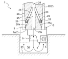
- a first fluid discharge hole provided between the plurality of cartridges on the distal end surface, the fluid passage for conveying the cutting fluid in the direction of the rotation axis of the tool body.
- a second discharge hole provided on the outer peripheral portion of the tool main body and facing the cutting edge of the cutting blade.
- the cutting fluid discharge hole is composed of the first discharge hole provided in the tip surface of the tool body and the second discharge hole provided in the outer peripheral portion of the tool body
- the first discharge is performed.
- the cutting fluid can be discharged toward the hole bottom of a workpiece at the time of inner surface processing of a blind hole.
- the cutting fluid discharged from the first discharge hole is reflected at the bottom of the hole and rises along the inner wall of the hole to form a flow toward the opening.
- the chips are discharged from the periphery of the tool body without accumulating at the hole bottom.
- the cutting edge is cooled by the cutting fluid discharged from the second discharge hole toward the cutting edge, and the adhesion of chips to the cutting edge is prevented.
- the boring tool of this configuration it is possible to supply the cutting fluid in the direction of the rotation axis of the tool body through the first discharge holes and supply the cutting fluid to the cutting edge through the second discharge holes. That is, the cutting fluid can be supplied from both the first discharge hole and the second discharge hole toward the perforated part. As a result, it is possible to enhance the chip discharging effect and the blade edge cooling effect and suppress wear of the cutting blade.
- Another characteristic configuration of the present invention is that an adjusting mechanism for adjusting a discharge amount of the cutting fluid is provided in the first discharge hole and the second discharge hole.
- the internal machining of the tool body can be minimized, and the amount of the cutting fluid discharged from the first discharge hole and the second discharge hole can be easily changed according to the processing conditions of the drilled portion with a simple configuration.
- the discharge of cutting fluid from the first discharge hole is adjusted to give priority to chip discharge, or the cutting fluid discharge from the second discharge hole is increased to give priority to cooling of the cutting edge.
- Another feature of the present invention is that at least one of the plurality of cartridges is provided with a flow portion through which the cutting fluid discharged from the first discharge hole flows regardless of the position of the adjustable cartridge. It is in.
- the cartridge is adjusted in the radial direction on the tip surface of the tool body according to the diameter of the inner surface. For this reason, the cartridge whose position is adjusted with respect to the supply direction of the cutting fluid discharged from the first discharge holes may interfere.
- the flow passage is provided with the cutting fluid regardless of the position of the cartridge that can be adjusted, the cutting fluid is surely supplied to the perforated portion to be processed by the flow portion. be able to.
- FIG. 3 is an exploded perspective view of a boring tool.
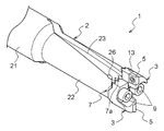
- FIG. 3 is a perspective view of a boring tool.
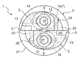
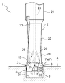
- FIG. 3 is a front view of the tip side of the boring tool. These are figures which show the state which is giving the inner surface process to the blind hole. These are the fragmentary sectional views of the boring tool in the state where inner surface processing is given to the blind hole.
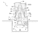
- FIG. 3 is a partial cross-sectional view of a boring tool. These are the fragmentary sectional views of the boring tool in the state where inner surface processing is given to the penetration hole. These are the fragmentary sectional views of the boring tool in the state where inner surface processing is given to the blind hole.
- FIG. 1 to 3 show a boring tool 1 according to the present invention.
- the boring tool 1 includes a tool body 2 mounted on a spindle (not shown) of a rotary machine tool, and a cartridge 3 having a cutting edge 5.
- the two cartridges 3 are attached to the front end surface 7 of the tool main body 2 in an offset state by approximately 180 degrees, and the position can be adjusted in the radial direction.
- the cutting blade 5 is attached to each of the cartridges 3 by fastening screws 8 and is configured to be replaceable.
- the cartridge 3 is mounted on the tool body 2 by a clamp screw 9.
- the front end surface 7 is entirely subjected to serration processing (a serration portion 7a), and the mounting surface 10 of the cartridge 3 is also subjected to uneven processing corresponding to the serration portion 7a.
- the front end surface 7 is provided with two screw holes 11 into which the clamp screws 9 are inserted.
- the clamp screw 9 is inserted into the screw hole 11 through an oval hole 12 provided in the cartridge 3. If the clamp screw 9 is loosened, the cartridge 3 can be individually adjusted in the radial direction within the range allowed by the oval hole 12.
- a through hole 13 is formed in a radial direction from the outer wall portion along the outer periphery of the distal end surface 7 toward the oval hole 12.
- the through hole 13 is provided in a direction along the serration portion 7 a of the distal end surface 7, and an adjustment screw 14 is housed in the through hole 13.
- the adjustment screw 14 changes the relative position between the clamp screw 9 and the cartridge 3 and is formed of, for example, a holoset.
- the adjusting screw 14 is rotated, for example, clockwise from the outside of the through hole 13, the tip of the adjusting screw 14 is exposed from the through hole 13 toward the clamp screw 9 inserted into the oval hole 12, and the clamp screw is exposed. 9 is pressed. That is, the adjustment screw 14 is located between the clamp screw 9 and the inner peripheral surface of the oval hole 12 of the cartridge 3. As a result, the cartridge 3 moves relatively radially away from the clamp screw 9 along the serration portion 7a of the tip surface 7.
- the adjusting screw 14 When the adjusting screw 14 is rotated, for example, counterclockwise, the tip of the adjusting screw 14 exposed from the through hole 13 is retracted. Thus, the radial position of the cartridge 3 can be changed by operating the adjustment screw 14.
- the tool body 2 includes a shank portion 21 and a body portion 22 that is continuous with the tip end side of the shank portion 21. Both the shank part 21 and the main body part 22 are formed in a cylindrical shape, and the main body part 22 has a smaller diameter.
- a groove portion 23 is formed on the outer peripheral portion of the main body portion 22 so as to continue from the distal end side of the shank portion 21 toward the distal end surface 7.
- the groove 23 has a wide shape through which chips can pass and is inclined clockwise from the direction along the axis of rotation, and the tip side (tip surface 7 side) of the groove 23 faces the lower side of the cutting blade 5. .
- the groove 23 facilitates the discharge of chips to the outside. By making the groove 23 as deep as possible, chips are easily discharged from the groove 23.
- the tool body 2 is provided with a fluid passage 24 for conveying the cutting fluid in the direction of the rotation axis.
- a first discharge hole 25 is formed in the center of the tip surface 7 of the tool body 2
- a second discharge hole 26 is formed in the outer peripheral portion of the body portion 22 of the tool body 2.
- the second discharge hole 26 is formed in the groove 23 and is provided at a position close to the tip surface 7. Both the first discharge hole 25 and the second discharge hole 26 communicate with the liquid passage 24.
- the first discharge hole 25 is disposed between the two cartridges 3 and supplies the cutting fluid toward the bottom of the drilled part to be processed.
- a concave portion is formed in the inward side portion facing the first discharge hole 25 as a flow portion 27 through which the cutting fluid discharged from the first discharge hole 25 flows.
- the position of the cartridge 3 is adjusted in the radial direction on the distal end surface 7 of the tool body 2 in accordance with the diameter to be processed on the inner surface.
- the circulation part (recessed part) 27 is configured in such a shape that the cutting fluid discharged from the first discharge hole 25 flows regardless of the position of the adjustable cartridge 3.
- the second discharge holes 26 are provided one by one for the cartridge 3 and supply cutting fluid toward the cutting edge.
- the boring tool 1 is provided with an adjustment mechanism that allows the discharge amount of the cutting fluid to be adjusted in the first discharge hole 25 and the second discharge hole 26.
- a female screw portion 25 a is formed on the inner surface of the first discharge hole 25, and a female screw portion 26 a is formed on the inner surface of the second discharge hole 26.
- the adjusting mechanism includes female screw portions 25a and 26a and a screw member 28 that can be screwed into the female screw portions 25a and 26a.
- the screw member 28 has a through hole with an arbitrary diameter.
- the discharge of cutting fluid from the first discharge hole 25 is adjusted to give priority to chip discharge, or the cutting fluid discharge amount from the second discharge hole 26 is given priority to cooling of the cutting edge. It can be adjusted to increase.
- the adjusting mechanism (the female screw portions 25a and 26a and the screw member 28) may be configured to be able to block the discharge of the cutting fluid from the first discharge hole 25 and the second discharge hole 26, respectively.
- the discharge of the cutting fluid from the first discharge hole 25 and the second discharge hole 26 can be blocked separately. Accordingly, the cutting fluid is supplied to one of the blade tip and the bottom portion 31 of the drilling portion 30 and the cutting fluid to both the blade tip and the bottom portion 31 of the punching portion 30 according to the processing conditions of the drilling portion 30 with a simple configuration. Can be easily switched to the mode of supplying the.
- the first discharge hole 25 and the second discharge hole 26 are opened.
- the cutting fluid is supplied from the first discharge hole 25 toward the bottom 31 of the perforated portion 30 of the workpiece A, and the cutting fluid is supplied from the second discharge hole 26 toward the cutting edge of the cutting blade 5.
- the cutting fluid discharged from the first discharge holes 25 is reflected on the bottom 31 of the punched portion 30 of the workpiece A, and rises along the inner wall surface of the punched portion 30 to form a flow toward the opening.
- chips are discharged from the periphery of the tool body 2 to the outside without accumulating on the bottom 31.
- the cutting blade 5 is cooled by the cutting fluid supplied from the second discharge hole 26, and the attachment of chips to the cutting blade 5 is also prevented.
- the boring tool 1 according to the present invention may include a connecting shaft instead of the shank portion 21.
- the concave portion is formed as the flow portion 27 through which the cutting fluid discharged from the first discharge hole 25 flows in the cartridge 3
- the distribution unit 27 may be provided only in a part of the plurality of cartridges 3. Further, when the discharge region of the first discharge hole 25 is secured in a state where a plurality of cartridges 3 are mounted, the cartridge 3 may not be provided with the flow portion 27.
- the boring tool 1 shields the second discharge hole 26 with the screw member 28 when machining the inner surface of the blind hole, and only supplies the cutting fluid in the direction of the rotation axis through the first discharge hole 25. You may comprise so that it may perform (FIG. 8).
- the adjustment mechanism for adjusting the discharge amount of the cutting fluid is configured by the female screw portions 25a and 26a and the screw member 28 .
- the adjustment mechanism may be configured to shield part or all of the first discharge hole 25 and the second discharge hole 26 with a cover body or the like, for example.
Landscapes
- Engineering & Computer Science (AREA)
- Mechanical Engineering (AREA)
- Cutting Tools, Boring Holders, And Turrets (AREA)
- Drilling Tools (AREA)
- Drilling And Boring (AREA)
Abstract
Description
本構成のボーリング工具であれば、このように第1吐出孔による工具本体の回転軸方向への切削液の供給と、第2吐出孔による刃先への切削液の供給とを行うことができる。すなわち、穿孔部に向けて第1吐出孔と第2吐出孔との両方から切削液を供給することができる。その結果、切屑の排出効果及び刃先の冷却効果を高めて切刃の摩耗を抑制することができる。
そこで、本構成では、第1吐出孔及び第2吐出孔に切削液の吐出量を調整する調整機構を設けている。これにより、工具本体の内部加工を必要最小限にでき、簡単な構成にて穿孔部の加工条件に応じて、第1吐出孔及び第2吐出孔から吐出される切削液の吐出量を容易に調整することができる。その結果、例えば切屑の排出を優先して第1吐出孔からの切削液の吐出量が増すよう調整したり、刃先の冷却を優先して第2吐出孔からの切削液の吐出量が増すよう調整することができる。
図1~図3に、本発明によるボーリング工具1を示す。ボーリング工具1は、回転工作機械の主軸(図示しない)に装着される工具本体2と、切刃5を有するカートリッジ3とを備える。2つのカートリッジ3が、工具本体2の先端面7に略180度オフセットされた状態で取付けられており、径方向に位置調整が可能である。切刃5は、締付けネジ8によってカートリッジ3の各々に取付けられており、交換可能に構成されている。
(1)本発明によるボーリング工具1は、シャンク部21に代えて、連結軸を備えるものであってもよい。
2 工具本体
3 カートリッジ
5 切刃
7 先端面
9 クランプねじ
12 長円形孔
13 貫通孔
14 調整ねじ
21 シャンク部
22 本体部
24 通液路
25 第1吐出孔
26 第2吐出孔
27 流通部
28 ねじ部材
30 穿孔部
Claims (3)
- 回転工作機械の主軸に装着される工具本体と、
前記工具本体の先端面に取付けられ、切刃を有し径方向に位置調整可能な複数のカートリッジと、を備え、
前記工具本体にその回転軸方向に切削液を搬送する通液路を備え、
前記切削液の吐出孔が、前記先端面において前記複数のカートリッジの間に設けられた第1吐出孔と、前記工具本体の外周部に設けられ前記切刃の刃先に向く第2吐出孔とによって構成してあるボーリング工具。 - 前記第1吐出孔及び前記第2吐出孔に前記切削液の吐出量を調整する調整機構を設けた請求項1に記載のボーリング工具。
- 前記複数のカートリッジの少なくとも1つに調整可能な当該カートリッジの位置に係わりなく前記第1吐出孔から吐出される前記切削液が流通する流通部が設けてある請求項1又は2に記載のボーリング工具。
Priority Applications (7)
| Application Number | Priority Date | Filing Date | Title |
|---|---|---|---|
| PCT/JP2014/062401 WO2015170390A1 (ja) | 2014-05-08 | 2014-05-08 | ボーリング工具 |
| US15/306,920 US10086439B2 (en) | 2014-05-08 | 2014-05-08 | Boring tool |
| JP2016517767A JP6293876B2 (ja) | 2014-05-08 | 2014-05-08 | ボーリング工具 |
| EP14891200.9A EP3141325B1 (en) | 2014-05-08 | 2014-05-08 | Boring tool |
| CN201480078281.0A CN106457416B (zh) | 2014-05-08 | 2014-05-08 | 镗削工具 |
| KR1020167028489A KR101974846B1 (ko) | 2014-05-08 | 2014-05-08 | 보링 공구 |
| TW104114131A TWI656926B (zh) | 2014-05-08 | 2015-05-04 | 搪孔工具 |
Applications Claiming Priority (1)
| Application Number | Priority Date | Filing Date | Title |
|---|---|---|---|
| PCT/JP2014/062401 WO2015170390A1 (ja) | 2014-05-08 | 2014-05-08 | ボーリング工具 |
Publications (1)
| Publication Number | Publication Date |
|---|---|
| WO2015170390A1 true WO2015170390A1 (ja) | 2015-11-12 |
Family
ID=54392259
Family Applications (1)
| Application Number | Title | Priority Date | Filing Date |
|---|---|---|---|
| PCT/JP2014/062401 Ceased WO2015170390A1 (ja) | 2014-05-08 | 2014-05-08 | ボーリング工具 |
Country Status (7)
| Country | Link |
|---|---|
| US (1) | US10086439B2 (ja) |
| EP (1) | EP3141325B1 (ja) |
| JP (1) | JP6293876B2 (ja) |
| KR (1) | KR101974846B1 (ja) |
| CN (1) | CN106457416B (ja) |
| TW (1) | TWI656926B (ja) |
| WO (1) | WO2015170390A1 (ja) |
Cited By (2)
| Publication number | Priority date | Publication date | Assignee | Title |
|---|---|---|---|---|
| US20230058499A1 (en) * | 2019-10-07 | 2023-02-23 | Muri Invest & Management Ug | Zerspanungswerkzeug und Verfahren zur spanabhebenden Bearbeitung sowie Bearbeitungskopf fuer ein Zerspanungswerkzeug |
| JP7340168B1 (ja) | 2022-12-21 | 2023-09-07 | 株式会社タンガロイ | 切削工具とそのボディ |
Families Citing this family (9)
| Publication number | Priority date | Publication date | Assignee | Title |
|---|---|---|---|---|
| US11154936B2 (en) * | 2016-09-29 | 2021-10-26 | Kyocera Corporation | Cutting tool and method of manufacturing machined product using them |
| KR200490934Y1 (ko) * | 2018-01-08 | 2020-01-23 | (주)엠케이트레이딩 | 볼링공의 스위치 그립용 아웃터 슬리브 커터 |
| CN108247302B (zh) * | 2018-04-04 | 2024-02-27 | 四川华都核设备制造有限公司 | 一种控制棒驱动机构盲孔棒行程套管加工方法及装置 |
| CN110496976B (zh) * | 2018-05-17 | 2024-12-06 | 昆山科森科技股份有限公司 | 用于电子笔杆加工的刀柄和刀粒机构 |
| JP7207983B2 (ja) * | 2018-12-10 | 2023-01-18 | 株式会社Subaru | ドリル、穿孔ユニット及び被穿孔品を製作する方法 |
| CN110935897B (zh) * | 2019-12-13 | 2020-12-04 | 河南理工大学 | 一种旋转式多刀片切换装置 |
| JP7223298B2 (ja) * | 2021-07-20 | 2023-02-16 | 株式会社タンガロイ | シャンクおよびこれを備えた切削工具 |
| DE202022000109U1 (de) | 2022-01-06 | 2023-04-17 | Nsh Technology Gmbh | Drehwerkzeug zur spanenden Bearbeitung von unrunden Profilen |
| CN116652687B (zh) * | 2023-07-21 | 2023-10-20 | 江苏竣昌科技有限公司 | 一种镁合金工件镗削用加工面冷却设备 |
Citations (5)
| Publication number | Priority date | Publication date | Assignee | Title |
|---|---|---|---|---|
| US4168925A (en) * | 1977-04-25 | 1979-09-25 | Cri-Dan | Device for boring out tubes with coolant liquid injection |
| JPH0596444A (ja) * | 1991-03-29 | 1993-04-20 | Tama Seimitsu Kk | バイトホルダー |
| JPH0825111A (ja) * | 1994-07-08 | 1996-01-30 | Toshiba Tungaloy Co Ltd | 旋削工具 |
| JPH10166219A (ja) * | 1996-12-09 | 1998-06-23 | Unisia Jecs Corp | 孔開け用切削工具 |
| JP2008221400A (ja) * | 2007-03-13 | 2008-09-25 | Hitachi Constr Mach Co Ltd | 切削加工装置 |
Family Cites Families (32)
| Publication number | Priority date | Publication date | Assignee | Title |
|---|---|---|---|---|
| US3037264A (en) * | 1959-09-08 | 1962-06-05 | Carl W Mossberg | Coolant type milling cutter |
| US3625624A (en) * | 1970-01-13 | 1971-12-07 | Galaxy Wedgebore Corp | Cutting assembly |
| US3782849A (en) * | 1970-12-01 | 1974-01-01 | S Mizoguchi | Boring head |
| US3795454A (en) * | 1971-10-01 | 1974-03-05 | S Elchyshyn | Adjustable boring bar with lubricant passages |
| DE7523920U (de) * | 1975-07-26 | 1977-01-20 | Komet Stahlhalter- Und Werkzeugfabrik Robert Breuning Gmbh, 7122 Besigheim | Bohrstange o.dgl. |
| DE3204923C2 (de) | 1982-02-12 | 1987-04-23 | Stellram GmbH, 6056 Heusenstamm | Werkzeug zum Aufbohren von Bohrungen |
| DE3204922C2 (de) * | 1982-02-12 | 1987-02-12 | Stellram GmbH, 6056 Heusenstamm | Werkzeug zum Aufbohren von Bohrungen |
| DE3622638A1 (de) | 1985-09-16 | 1987-03-26 | Koyemann Werkzeuge Gmbh | Bohrkopf mit vorkopf liegenden schneiden |
| DE8526482U1 (de) * | 1985-09-16 | 1985-11-14 | Koyemann Werkzeuge Gmbh, 4006 Erkrath | Bohrkopf mit vorkopf liegenden Schneiden |
| CH672605A5 (ja) * | 1987-10-12 | 1989-12-15 | Philippe Audemars | |
| SU1685618A2 (ru) * | 1989-11-13 | 1991-10-23 | Ленинградский механический институт им.Маршала Советского Союза Устинова Д.Ф. | Расточна головка |
| SE504313C2 (sv) * | 1992-02-24 | 1997-01-13 | Sandvik Ab | Uppborrningsverktyg |
| DE4224772C2 (de) * | 1992-07-27 | 1995-01-12 | Koyemann Werkzeuge Gmbh | Werkzeugkopf |
| DE19719893A1 (de) * | 1997-03-03 | 1998-11-19 | Maier Kg Andreas | Reib- und Senk-Schneidwerkzeug mit Kühlmittelzufuhr |
| AU7716098A (en) * | 1997-06-05 | 1998-12-21 | Gregory S. Antoun | Tool holder with integral coolant passage and replaceable nozzle |
| TW402977U (en) * | 1999-05-20 | 2000-08-21 | Tsai Shr Shiung | Improved double-blade boring cutter structure |
| DE19944851C2 (de) * | 1999-09-18 | 2001-10-04 | Koyemann Werkzeuge Gmbh | Bohrkopf mit Verstellschraube |
| SE518154C2 (sv) * | 1999-12-21 | 2002-09-03 | Sandvik Ab | Borr bestående av borrspetsparti som är löstagbart förenat med ett borrskaft |
| TW478418U (en) * | 2000-08-31 | 2002-03-01 | Kuen-Chi Luo | Structure improvement for holes tapping tool |
| TW582321U (en) * | 2001-03-01 | 2004-04-01 | Ann Way Machine Tools Co Ltd | Tool chuck for holes tapping and cutting tools capable of guarding coolant |
| TW542026U (en) * | 2002-06-06 | 2003-07-11 | Shr-Shiung Tsai | Ultra fine tuning structure for precision boring device |
| CN2573122Y (zh) * | 2002-09-20 | 2003-09-17 | 昆山力捷塑胶五金有限公司 | 搪孔刀座调整结构 |
| DE102004044267A1 (de) * | 2004-09-10 | 2006-03-16 | Robert Koch GmbH Präzisionswerkzeuge | Spannmutter als Werkzeughalterteil für ein Werkzeug |
| JP2008200801A (ja) | 2007-02-20 | 2008-09-04 | Hitachi Constr Mach Co Ltd | 切削工具 |
| US9004827B2 (en) * | 2007-06-07 | 2015-04-14 | Allied Machine & Engineering Corp. | Adjustable indexable drill and modular system and holder |
| CN201136073Y (zh) * | 2008-01-11 | 2008-10-22 | 中国石化集团胜利石油管理局井下作业公司 | 一种加工工件内螺纹的复合刀具 |
| CN201231325Y (zh) * | 2008-06-23 | 2009-05-06 | 漳州升源机械工业有限公司 | 搪孔刀头 |
| JP5287426B2 (ja) * | 2008-09-01 | 2013-09-11 | 三菱マテリアル株式会社 | 切削工具 |
| TWM432483U (en) * | 2012-02-14 | 2012-07-01 | chun-cai Zhang | Hole boring tool structure for preventing deflected sliding |
| CN103121121B (zh) * | 2013-02-28 | 2015-06-10 | 常州东风农机集团有限公司 | 可转位钻镗倒角复合刀具 |
| CN203371056U (zh) * | 2013-07-29 | 2014-01-01 | 成都成林数控刀具有限公司 | 一种新型的双刃镗刀冷却孔结构 |
| DE202013104099U1 (de) * | 2013-09-10 | 2013-09-24 | Good-Tec Co., Ltd. | Bearbeitungswerkzeughalter mit Fähigkeit zur Vibrationsunterdrückung und Schmierungs-Funktion |
-
2014
- 2014-05-08 EP EP14891200.9A patent/EP3141325B1/en active Active
- 2014-05-08 JP JP2016517767A patent/JP6293876B2/ja active Active
- 2014-05-08 KR KR1020167028489A patent/KR101974846B1/ko active Active
- 2014-05-08 CN CN201480078281.0A patent/CN106457416B/zh active Active
- 2014-05-08 US US15/306,920 patent/US10086439B2/en active Active
- 2014-05-08 WO PCT/JP2014/062401 patent/WO2015170390A1/ja not_active Ceased
-
2015
- 2015-05-04 TW TW104114131A patent/TWI656926B/zh active
Patent Citations (5)
| Publication number | Priority date | Publication date | Assignee | Title |
|---|---|---|---|---|
| US4168925A (en) * | 1977-04-25 | 1979-09-25 | Cri-Dan | Device for boring out tubes with coolant liquid injection |
| JPH0596444A (ja) * | 1991-03-29 | 1993-04-20 | Tama Seimitsu Kk | バイトホルダー |
| JPH0825111A (ja) * | 1994-07-08 | 1996-01-30 | Toshiba Tungaloy Co Ltd | 旋削工具 |
| JPH10166219A (ja) * | 1996-12-09 | 1998-06-23 | Unisia Jecs Corp | 孔開け用切削工具 |
| JP2008221400A (ja) * | 2007-03-13 | 2008-09-25 | Hitachi Constr Mach Co Ltd | 切削加工装置 |
Cited By (3)
| Publication number | Priority date | Publication date | Assignee | Title |
|---|---|---|---|---|
| US20230058499A1 (en) * | 2019-10-07 | 2023-02-23 | Muri Invest & Management Ug | Zerspanungswerkzeug und Verfahren zur spanabhebenden Bearbeitung sowie Bearbeitungskopf fuer ein Zerspanungswerkzeug |
| JP7340168B1 (ja) | 2022-12-21 | 2023-09-07 | 株式会社タンガロイ | 切削工具とそのボディ |
| JP2024088890A (ja) * | 2022-12-21 | 2024-07-03 | 株式会社タンガロイ | 切削工具とそのボディ |
Also Published As
| Publication number | Publication date |
|---|---|
| EP3141325A1 (en) | 2017-03-15 |
| JP6293876B2 (ja) | 2018-03-14 |
| US10086439B2 (en) | 2018-10-02 |
| EP3141325B1 (en) | 2021-04-14 |
| JPWO2015170390A1 (ja) | 2017-04-20 |
| TW201607647A (zh) | 2016-03-01 |
| CN106457416B (zh) | 2018-11-27 |
| EP3141325A4 (en) | 2017-12-27 |
| KR101974846B1 (ko) | 2019-05-03 |
| KR20160130499A (ko) | 2016-11-11 |
| TWI656926B (zh) | 2019-04-21 |
| US20170043407A1 (en) | 2017-02-16 |
| CN106457416A (zh) | 2017-02-22 |
Similar Documents
| Publication | Publication Date | Title |
|---|---|---|
| JP6293876B2 (ja) | ボーリング工具 | |
| KR102362020B1 (ko) | 디스크 밀링 커터 및 그러한 디스크 밀링 커터를 포함하는 키트 | |
| US9676043B2 (en) | Slot milling disc and a rotatable mounting shaft for such a milling disc | |
| RU2525880C2 (ru) | Фрезерный инструмент с устройством непрерывной подачи жидкости | |
| RU2615967C2 (ru) | Режущий инструмент | |
| US10835968B2 (en) | Machining tool | |
| CN107000067A (zh) | 车刀 | |
| JP2020500721A (ja) | 加工工具 | |
| KR102495442B1 (ko) | 드릴, 천공 유닛 및 천공 방법 | |
| CN105312652A (zh) | 带有喷淋帽的切削工具 | |
| JPWO2012117817A1 (ja) | ガイドパッド、切削工具本体および切削工具 | |
| JP2010142889A (ja) | 工具保持具、工具保持具用切削液供給プレート及び切削加工方法 | |
| US7357607B2 (en) | Tool holder | |
| JP2008221400A (ja) | 切削加工装置 | |
| JP4966717B2 (ja) | 穴加工工具 | |
| JP2003136322A (ja) | 穴加工工具 | |
| JP2020055086A (ja) | 切屑搬送式切削工具 | |
| JP2014012308A (ja) | 刃先交換式切削工具 | |
| JP4876650B2 (ja) | 穴加工工具 | |
| JP2005034954A (ja) | 油穴付き切削工具および切削加工方法 | |
| JP2014012309A (ja) | 刃先交換式切削工具 | |
| JP6569403B2 (ja) | 刃先交換式切削工具 | |
| KR200488778Y1 (ko) | 인덱서블 드릴의 툴 바디 | |
| TW201605565A (zh) | 捨棄式鉸刀 | |
| JP2013018062A (ja) | クーラント穴付き穴加工工具 |
Legal Events
| Date | Code | Title | Description |
|---|---|---|---|
| 121 | Ep: the epo has been informed by wipo that ep was designated in this application |
Ref document number: 14891200 Country of ref document: EP Kind code of ref document: A1 |
|
| ENP | Entry into the national phase |
Ref document number: 2016517767 Country of ref document: JP Kind code of ref document: A |
|
| ENP | Entry into the national phase |
Ref document number: 20167028489 Country of ref document: KR Kind code of ref document: A |
|
| WWE | Wipo information: entry into national phase |
Ref document number: 15306920 Country of ref document: US |
|
| REEP | Request for entry into the european phase |
Ref document number: 2014891200 Country of ref document: EP |
|
| WWE | Wipo information: entry into national phase |
Ref document number: 2014891200 Country of ref document: EP |
|
| NENP | Non-entry into the national phase |
Ref country code: DE |