WO2015170431A1 - Système de climatisation - Google Patents
Système de climatisation Download PDFInfo
- Publication number
- WO2015170431A1 WO2015170431A1 PCT/JP2014/084498 JP2014084498W WO2015170431A1 WO 2015170431 A1 WO2015170431 A1 WO 2015170431A1 JP 2014084498 W JP2014084498 W JP 2014084498W WO 2015170431 A1 WO2015170431 A1 WO 2015170431A1
- Authority
- WO
- WIPO (PCT)
- Prior art keywords
- refrigerant
- indoor unit
- type indoor
- refrigerant pipe
- air conditioner
- Prior art date
- Legal status (The legal status is an assumption and is not a legal conclusion. Google has not performed a legal analysis and makes no representation as to the accuracy of the status listed.)
- Ceased
Links
Images


Classifications
-
- F—MECHANICAL ENGINEERING; LIGHTING; HEATING; WEAPONS; BLASTING
- F25—REFRIGERATION OR COOLING; COMBINED HEATING AND REFRIGERATION SYSTEMS; HEAT PUMP SYSTEMS; MANUFACTURE OR STORAGE OF ICE; LIQUEFACTION SOLIDIFICATION OF GASES
- F25B—REFRIGERATION MACHINES, PLANTS OR SYSTEMS; COMBINED HEATING AND REFRIGERATION SYSTEMS; HEAT PUMP SYSTEMS
- F25B13/00—Compression machines, plants or systems, with reversible cycle
-
- F—MECHANICAL ENGINEERING; LIGHTING; HEATING; WEAPONS; BLASTING
- F24—HEATING; RANGES; VENTILATING
- F24F—AIR-CONDITIONING; AIR-HUMIDIFICATION; VENTILATION; USE OF AIR CURRENTS FOR SCREENING
- F24F13/00—Details common to, or for air-conditioning, air-humidification, ventilation or use of air currents for screening
- F24F13/30—Arrangement or mounting of heat-exchangers
-
- F—MECHANICAL ENGINEERING; LIGHTING; HEATING; WEAPONS; BLASTING
- F24—HEATING; RANGES; VENTILATING
- F24F—AIR-CONDITIONING; AIR-HUMIDIFICATION; VENTILATION; USE OF AIR CURRENTS FOR SCREENING
- F24F3/00—Air-conditioning systems in which conditioned primary air is supplied from one or more central stations to distributing units in the rooms or spaces where it may receive secondary treatment; Apparatus specially designed for such systems
- F24F3/06—Air-conditioning systems in which conditioned primary air is supplied from one or more central stations to distributing units in the rooms or spaces where it may receive secondary treatment; Apparatus specially designed for such systems characterised by the arrangements for the supply of heat-exchange fluid for the subsequent treatment of primary air in the room units
- F24F3/065—Air-conditioning systems in which conditioned primary air is supplied from one or more central stations to distributing units in the rooms or spaces where it may receive secondary treatment; Apparatus specially designed for such systems characterised by the arrangements for the supply of heat-exchange fluid for the subsequent treatment of primary air in the room units with a plurality of evaporators or condensers
-
- F—MECHANICAL ENGINEERING; LIGHTING; HEATING; WEAPONS; BLASTING
- F24—HEATING; RANGES; VENTILATING
- F24F—AIR-CONDITIONING; AIR-HUMIDIFICATION; VENTILATION; USE OF AIR CURRENTS FOR SCREENING
- F24F5/00—Air-conditioning systems or apparatus not covered by F24F1/00 or F24F3/00, e.g. using solar heat or combined with household units such as an oven or water heater
- F24F5/0089—Systems using radiation from walls or panels
-
- F—MECHANICAL ENGINEERING; LIGHTING; HEATING; WEAPONS; BLASTING
- F28—HEAT EXCHANGE IN GENERAL
- F28D—HEAT-EXCHANGE APPARATUS, NOT PROVIDED FOR IN ANOTHER SUBCLASS, IN WHICH THE HEAT-EXCHANGE MEDIA DO NOT COME INTO DIRECT CONTACT
- F28D1/00—Heat-exchange apparatus having stationary conduit assemblies for one heat-exchange medium only, the media being in contact with different sides of the conduit wall, in which the other heat-exchange medium is a large body of fluid, e.g. domestic or motor car radiators
- F28D1/02—Heat-exchange apparatus having stationary conduit assemblies for one heat-exchange medium only, the media being in contact with different sides of the conduit wall, in which the other heat-exchange medium is a large body of fluid, e.g. domestic or motor car radiators with heat-exchange conduits immersed in the body of fluid
- F28D1/04—Heat-exchange apparatus having stationary conduit assemblies for one heat-exchange medium only, the media being in contact with different sides of the conduit wall, in which the other heat-exchange medium is a large body of fluid, e.g. domestic or motor car radiators with heat-exchange conduits immersed in the body of fluid with tubular conduits
- F28D1/047—Heat-exchange apparatus having stationary conduit assemblies for one heat-exchange medium only, the media being in contact with different sides of the conduit wall, in which the other heat-exchange medium is a large body of fluid, e.g. domestic or motor car radiators with heat-exchange conduits immersed in the body of fluid with tubular conduits the conduits being bent, e.g. in a serpentine or zig-zag
- F28D1/0477—Heat-exchange apparatus having stationary conduit assemblies for one heat-exchange medium only, the media being in contact with different sides of the conduit wall, in which the other heat-exchange medium is a large body of fluid, e.g. domestic or motor car radiators with heat-exchange conduits immersed in the body of fluid with tubular conduits the conduits being bent, e.g. in a serpentine or zig-zag the conduits being bent in a serpentine or zig-zag
-
- F—MECHANICAL ENGINEERING; LIGHTING; HEATING; WEAPONS; BLASTING
- F28—HEAT EXCHANGE IN GENERAL
- F28F—DETAILS OF HEAT-EXCHANGE AND HEAT-TRANSFER APPARATUS, OF GENERAL APPLICATION
- F28F1/00—Tubular elements; Assemblies of tubular elements
- F28F1/10—Tubular elements and assemblies thereof with means for increasing heat-transfer area, e.g. with fins, with projections, with recesses
- F28F1/12—Tubular elements and assemblies thereof with means for increasing heat-transfer area, e.g. with fins, with projections, with recesses the means being only outside the tubular element
- F28F1/14—Tubular elements and assemblies thereof with means for increasing heat-transfer area, e.g. with fins, with projections, with recesses the means being only outside the tubular element and extending longitudinally
- F28F1/20—Tubular elements and assemblies thereof with means for increasing heat-transfer area, e.g. with fins, with projections, with recesses the means being only outside the tubular element and extending longitudinally the means being attachable to the element
-
- F—MECHANICAL ENGINEERING; LIGHTING; HEATING; WEAPONS; BLASTING
- F25—REFRIGERATION OR COOLING; COMBINED HEATING AND REFRIGERATION SYSTEMS; HEAT PUMP SYSTEMS; MANUFACTURE OR STORAGE OF ICE; LIQUEFACTION SOLIDIFICATION OF GASES
- F25B—REFRIGERATION MACHINES, PLANTS OR SYSTEMS; COMBINED HEATING AND REFRIGERATION SYSTEMS; HEAT PUMP SYSTEMS
- F25B2313/00—Compression machines, plants or systems with reversible cycle not otherwise provided for
- F25B2313/006—Compression machines, plants or systems with reversible cycle not otherwise provided for two pipes connecting the outdoor side to the indoor side with multiple indoor units
-
- F—MECHANICAL ENGINEERING; LIGHTING; HEATING; WEAPONS; BLASTING
- F25—REFRIGERATION OR COOLING; COMBINED HEATING AND REFRIGERATION SYSTEMS; HEAT PUMP SYSTEMS; MANUFACTURE OR STORAGE OF ICE; LIQUEFACTION SOLIDIFICATION OF GASES
- F25B—REFRIGERATION MACHINES, PLANTS OR SYSTEMS; COMBINED HEATING AND REFRIGERATION SYSTEMS; HEAT PUMP SYSTEMS
- F25B2313/00—Compression machines, plants or systems with reversible cycle not otherwise provided for
- F25B2313/023—Compression machines, plants or systems with reversible cycle not otherwise provided for using multiple indoor units
- F25B2313/0232—Compression machines, plants or systems with reversible cycle not otherwise provided for using multiple indoor units with bypasses
-
- F—MECHANICAL ENGINEERING; LIGHTING; HEATING; WEAPONS; BLASTING
- F25—REFRIGERATION OR COOLING; COMBINED HEATING AND REFRIGERATION SYSTEMS; HEAT PUMP SYSTEMS; MANUFACTURE OR STORAGE OF ICE; LIQUEFACTION SOLIDIFICATION OF GASES
- F25B—REFRIGERATION MACHINES, PLANTS OR SYSTEMS; COMBINED HEATING AND REFRIGERATION SYSTEMS; HEAT PUMP SYSTEMS
- F25B2313/00—Compression machines, plants or systems with reversible cycle not otherwise provided for
- F25B2313/023—Compression machines, plants or systems with reversible cycle not otherwise provided for using multiple indoor units
- F25B2313/0234—Compression machines, plants or systems with reversible cycle not otherwise provided for using multiple indoor units in series arrangements
-
- F—MECHANICAL ENGINEERING; LIGHTING; HEATING; WEAPONS; BLASTING
- F25—REFRIGERATION OR COOLING; COMBINED HEATING AND REFRIGERATION SYSTEMS; HEAT PUMP SYSTEMS; MANUFACTURE OR STORAGE OF ICE; LIQUEFACTION SOLIDIFICATION OF GASES
- F25B—REFRIGERATION MACHINES, PLANTS OR SYSTEMS; COMBINED HEATING AND REFRIGERATION SYSTEMS; HEAT PUMP SYSTEMS
- F25B2500/00—Problems to be solved
- F25B2500/01—Geometry problems, e.g. for reducing size
-
- F—MECHANICAL ENGINEERING; LIGHTING; HEATING; WEAPONS; BLASTING
- F28—HEAT EXCHANGE IN GENERAL
- F28F—DETAILS OF HEAT-EXCHANGE AND HEAT-TRANSFER APPARATUS, OF GENERAL APPLICATION
- F28F2215/00—Fins
- F28F2215/06—Hollow fins; fins with internal circuits
-
- F—MECHANICAL ENGINEERING; LIGHTING; HEATING; WEAPONS; BLASTING
- F28—HEAT EXCHANGE IN GENERAL
- F28F—DETAILS OF HEAT-EXCHANGE AND HEAT-TRANSFER APPARATUS, OF GENERAL APPLICATION
- F28F2275/00—Fastening; Joining
- F28F2275/08—Fastening; Joining by clamping or clipping
- F28F2275/085—Fastening; Joining by clamping or clipping with snap connection
Definitions
- the present invention relates to an air conditioner. More specifically, the present invention relates to an apparatus provided with a convection type indoor unit and a radiation type indoor unit that prevents damage to the compressor and prevents deterioration of the reliability of the compressor.
- An air conditioner having a refrigerant pipe connecting a compressor, an outdoor heat exchanger, an expansion valve, a convection indoor unit, and these devices is generally used.
- cooled or heated air is blown by a fan into a room which is an air conditioning target space, and air is conditioned by circulating or convection in the room.
- air conditioning is also performed to cool or heat indoor air, which is a space to be air-conditioned, through a refrigerant in a radiant indoor unit.
- Patent Document 1 An air conditioner in which a radiation type indoor unit is added to an air conditioner equipped with a convection type indoor unit has already been proposed in Patent Document 1 by the present inventor.
- the present inventor has conducted experiments toward practical use of an air conditioner in which a radiant indoor unit is added to an air conditioner equipped with a convection type indoor unit, and refrigerant tubes of the radiant type indoor unit are arranged in parallel in the vertical direction.
- a plurality of straight pipes and connection pipes connecting between the upper end and the lower end of adjacent straight pipes are formed in a meandering shape (hereinafter, the refrigerant pipe is referred to as a “meander pipe”), It has been found that an oil reservoir is formed in the lower part of the refrigerant pipe.
- the refrigerant of the air conditioner partially circulates in the refrigerant pipe as a two-phase refrigerant of gas and liquid, and this refrigerant contains the lubricating oil of the compressor.
- the pool is thought to be the separation of the lubricating oil in the refrigerant. If the lubricating oil in the refrigerant is separated and lost, the compressor becomes insufficient in lubricating oil, and an excessive load is applied to the compressor, which may cause a failure.
- the cause of the separation of the lubricating oil in the refrigerant is not well understood, but may be considered as follows. That is, when a radiation type indoor unit is added to an air conditioner equipped with a convection type indoor unit, it can be considered in the same manner as when the refrigerant pipe becomes long.
- the capacity of the compressor is determined by a design that does not take into account the expansion of the radiant indoor unit. As a result, the capacity of the compressor is insufficient, and the flow rate of the refrigerant is reduced, which causes the radiant indoor unit to be reduced. It seems that an oil sump has occurred in the lower part of the refrigerant pipe.
- This measure can be solved by increasing the capacity of the compressor, but when adding a radiant indoor unit to an existing air conditioner, replace the existing compressor with a compressor with higher capacity. Is difficult in terms of cost. Further, in the case of a newly manufactured air conditioner, it is likely to increase the cost to increase the compression capacity by planning the deployment of a radiation type indoor unit that is not used or not.
- the present inventor has conducted extensive research on the solution of this problem on the side of the radiant indoor unit, and pays attention to the problem of oil sump unless the flow rate of the refrigerant flowing through the radiant indoor unit is reduced.
- the present invention has been completed.
- the present invention has been made to solve the above-mentioned problems, and in an air conditioner equipped with a convection type indoor unit and a radiation type indoor unit, it prevents separation of lubricating oil in the refrigerant and thus prevents damage to the compressor.
- the first object of the present invention is to provide an air conditioner that can prevent a reduction in the reliability of the compressor.
- a second object is to provide an air conditioner that prevents the flow rate of the refrigerant from decreasing even when the radiation type indoor unit is enlarged.
- the present invention includes at least an outdoor unit having a compressor, an outdoor heat exchanger and an expansion valve, an air conditioner having a convection type indoor unit and a refrigerant pipe connecting these devices, the convection type indoor unit, An air conditioner including a radiation-type indoor unit that is provided between the outdoor unit and has a refrigerant pipe having an inner diameter smaller than that of the refrigerant pipe for connecting the convection type indoor unit and the outdoor unit. .
- the inner diameter and length of the refrigerant pipe of the radiant indoor unit can be arbitrarily determined within the design range in which the air conditioner functions, as described below and in the embodiment.
- the inner diameter of the refrigerant pipe is too small, the flow rate of the refrigerant is increased, but the pressure loss due to the resistance increases, and the load on the compressor is increased, which seems to deteriorate the efficiency.
- the refrigerant pipe of an air conditioner [inner diameter 7.92 ⁇ (49.2mm 2 )] is a refrigerant pipe of a radiant indoor unit composed of two meandering pipes [inner diameter 4.75 ⁇ (17.7mm 2 )] To branch into two systems.
- the straight pipe part of the meandering pipe is arranged in the vertical direction.
- Total cross-sectional area of the refrigerant tube having an inner diameter 4.75 ⁇ (17.7mm 2) (35.4mm 2 ) is about 72% compared to the inside diameter of the refrigerant pipe 7.92 ⁇ (49.2mm 2), the inside diameter of the refrigerant pipe than the refrigerant pipe Therefore, the flow rate of the refrigerant in the refrigerant pipe is small.
- the number of heat generating elements of the radiation type indoor unit including the refrigerant pipe is six per one meandering pipe, and the number of the two meandering pipes, that is, the number of heat radiation plates of one unit is 12, which is the same as that of one radiation type indoor unit.
- a reference unit was used. The experiment was conducted with this reference unit.
- the refrigerant pipe of the refrigerant flowing through the refrigerant pipe of an air conditioner mm Inside diameter 11.1 ⁇ (96.7mm 2)] the radiation type indoor unit constituted by serpentine tubes of two systems [inner diameter 7.92Fai (49.2 mm 2 )] To branch into two systems.
- the straight pipe part of the meandering pipe is arranged in the vertical direction.
- Total cross-sectional area of the refrigerant tube having an inner diameter 7.92 ⁇ (49.2mm 2) (98.4mm 2 ) is 101.7% compared to the inside diameter of the refrigerant pipe 11.1 ⁇ (96.7mm 2), the flow rate of the refrigerant is substantially identical.
- the radiation type indoor unit constituted by serpentine tubes of two systems [inner diameter 6.4 ⁇ (32.2mm 2 Branches into two refrigerant piping systems.
- the straight pipe part of the meandering pipe is arranged in the vertical direction. If 4 lines are juxtaposed serpentine tube of two systems (two radiation type indoor unit), the total cross-sectional area of the refrigerant tube having an inner diameter of 6.4 ⁇ (32.2mm 2) (128.8mm 2 ) has an inner diameter of the refrigerant pipe Compared to the area of 13.88 ⁇ (151.2mm 2 ), it is 85.1%, and the flow velocity is faster.
- the refrigerant pipe becomes longer. Since the refrigerant moves from the vicinity of the inlet of the refrigerant pipe to the outlet while gradually radiating heat, there is a temperature difference between the vicinity of the inlet and the vicinity of the outlet, and the capability of the heating element of the radiation type indoor unit may not be sufficiently exhibited. That is, there arises a situation in which the heat dissipating ability of the heat generating element cannot be sufficiently exhibited due to uneven temperature of the heat generating element. In addition, the flow rate of the refrigerant is slowed down, causing oil accumulation.
- the radiant indoor unit has a branching part that branches the refrigerant flow into a plurality of parts, and a refrigerant branched by the branching part. And a collecting portion for collecting. If the inside diameter of the refrigerant pipe is reduced within the design range in which the air conditioner functions and a plurality of radiant indoor units are installed, the thermal efficiency of the radiant indoor unit as a whole can be increased.
- the refrigerant pipe of the radiant indoor unit has a plurality of straight pipes arranged in parallel in the vertical direction, and a connecting pipe that connects between the upper ends and lower ends of adjacent straight pipes, and is formed in a meandering shape. Is preferable from the viewpoint of smoothing the flow of the refrigerant.
- the plurality of straight pipes are covered with an elliptical heat radiating portion in which the outer surface of the opposing wall bulges outward, and the heat radiating portion is arranged in a broken line shape in which the end portions of the adjacent heat radiating portions are not continuous.
- the bulging portions of the heat radiating portion are arranged facing each other, the temperature difference in the vertical direction of the radiation type indoor unit becomes large. This is presumably because warming and cooling of the air is promoted by facing the bulging portions of the heat radiation part.
- the bulging part of a thermal radiation part is arrange
- a plurality of radiation type indoor units can be connected in series to the refrigerant circuit.
- a route through which some refrigerant flows to the outdoor unit and the convective indoor unit without passing through the radiant indoor unit If it is ensured, the pressure loss of the refrigerant caused by the radiation type indoor unit can be prevented, and the operation can be performed without applying a load to the compressor.
- the refrigerant pipe of the radiant type indoor unit is made smaller than the refrigerant pipe of the air conditioner, so that the flow velocity of the refrigerant flowing through the refrigerant pipe is reduced. It is possible to prevent the oil pool phenomenon that occurs in the refrigerant pipe of the radiation type indoor unit.
- the inner diameter of the refrigerant pipe of the radiation type indoor unit is made smaller than that of the refrigerant pipe of the air conditioner. It is possible to provide an air-conditioning apparatus that can prevent oil from being separated, thereby preventing damage to the compressor and preventing deterioration in the reliability of the compressor.
- the radiation type indoor unit is provided with a branching part that branches the flow of the refrigerant flowing through the refrigerant pipe into a plurality of parts and a collecting part that collects the refrigerant branched by the branching part. Even if it does, it can prevent that the flow velocity of the refrigerant
- FIG. 4 is a schematic explanatory diagram viewed from the AA direction in FIG. 3.
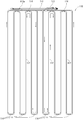
- FIG. 2 is a schematic plan view illustrating the structure of a refrigerant pipe of a radiant indoor unit, in which the refrigerant flow during heating is indicated by arrows.
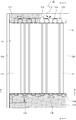
- FIG. 6 is a schematic front view illustrating the structure of the refrigerant pipe of the radiation type indoor unit illustrated in FIG.
- FIG. 5 is a schematic front view illustrating the structure of a refrigerant pipe in a modification of the radiation type indoor unit of the present invention.
- the air conditioner 100 includes a single outdoor unit 1 and two indoor units connected in series to the outdoor unit 1.
- One of the two indoor units is a general convection type indoor unit 2, and the other is a radiation type indoor unit 10.
- the convection type indoor unit 2 and the radiation type indoor unit 10 are installed in a room or the like having an air conditioning target area, and have a function of cooling or heating the air conditioning target area.
- the convection type indoor unit 2 and the radiant type indoor unit 10 are connected by a refrigerant pipe 7 for communication. Therefore, the convection type indoor unit 2 and the radiant type indoor unit 10 of the air conditioner 100 form part of the refrigerant circuit, and the refrigerant can be circulated through the refrigerant circuit, thereby enabling a cooling operation or a heating operation. It has become.
- each of the outdoor unit, the convection type indoor unit 2 and the radiation type indoor unit 10 has a single configuration, but is not limited to the illustrated number.
- the outdoor unit 1 has a known structure including a compressor 3, an outdoor heat exchanger 4, and an expansion valve 5.
- the convection type indoor unit 2 has a known structure including an indoor heat exchanger 6 and a blower fan (not shown) that sends air to the indoor heat exchanger 6.
- the indoor heat exchanger 6 functions as an evaporator during cooling operation, and functions as a condenser (heat radiator) during heating operation, and performs heat exchange between air supplied from a blower such as a fan (not shown) and the refrigerant. Then, heating air or cooling air to be supplied to the air conditioning target area is created.
- the devices are connected by a refrigerant pipe 7 and constitute a part of the refrigeration cycle (refrigerant circuit) of the air conditioner 100.
- the refrigeration cycle of the air conditioner 100 is provided with a radiation type indoor unit 10.
- the radiant indoor unit 10 includes a heating element 11 and a frame 12 that fixes and supports the heating element 11.
- the frame 12 includes vertical frames 12a and 12b that are erected in parallel in the vertical direction on both the left and right sides.
- a metal such as wood, synthetic resin, or aluminum can be adopted.
- the frame 12 includes a back plate serving as a reflective material or a heat insulating material that reflects radiant heat, but may have a structure without a back plate.
- a heating element 11 is disposed between the vertical frames 12a and 12b.
- the heating element 11 has a straight pipe 112 in which the longitudinal direction is arranged in the vertical direction and a plurality of pipes are arranged in parallel in the lateral direction, and a connecting pipe 114 that connects between the upper end and the lower end of the adjacent straight pipes 112.
- the refrigerant pipe 110 is formed by arranging the whole shape in a meandering manner. As shown in FIG. 3 in the refrigerant pipe 110, the straight pipe 112 is surrounded by a heat radiating area expanding member 111, and the heating element 11 is configured.
- the refrigerant pipe 110 may be made of a metal such as aluminum or copper, or other materials as required.
- a branch portion 113 that branches into a plurality of refrigerant flows through the refrigerant pipe 7, and in this embodiment, a branch portion 113, and a collecting portion 115 that collects the refrigerant branched by the branch portion 113,
- the connection port of the branch part 113 and the connection port of the concentration part 115 are each connected to the refrigerant pipe 7, and the radiation type indoor unit 10 is incorporated in the refrigerant circuit.
- the branch part 113 and the concentration part 115 are arrange
- FIG. As shown in a modification of the radiation type indoor unit), the branching portion 113 and the concentrating portion 115 may be arranged below the heating element 11.
- the branch part 113 includes branch pipes 113a and 113b.
- the refrigerant is divided by the branch pipes 113a and 113b, so that two refrigerant flows are obtained.
- the arrows in FIG. 6 indicate the flow of the refrigerant, and one flow by the branch pipe 113a flows through the six straight pipes 112 on the right side of FIG. 6 (second heating element 11b), and by the branch pipe 113b.
- the other flow flows in the six straight pipes 112 on the left side in FIG. 6 (first heating element 11a).
- These refrigerants merge at the collecting portion 115 and flow from the collecting portion 115 to the refrigerant circuit 7.
- the refrigerant flow indicated by the arrows is the refrigerant flow during heating.
- the flow of the refrigerant during cooling is the reverse of the flow during heating (the direction of the arrow is reversed).
- the reason for this setting is that, particularly during heating, when the refrigerant flowing in the heating element 11 flows from the center side to the outside side (that is, the refrigerant enters from the direction of the branch portion 113 and flows out toward the concentration portion 115). This is because the heat dissipation efficiency is better.
- the reason for this is as follows. That is, the temperature of the refrigerant is highest near the inlet of the refrigerant during heating, and gradually decreases as the temperature approaches the vicinity of the outlet as heat is dissipated, but the refrigerant inlet is outside the heating element 11.
- the heat is shielded by the vertical frames 12a and 12b (in other words, the outermost heat generation) due to the structure of the radiation type indoor unit 10 in the present embodiment.
- the body is in the shadow of the vertical frame), and it is difficult to say that the heat dissipation efficiency is the best.
- the inlet of the refrigerant is on the center side of the heating element 11, there is nothing to block the heat dissipation like the vertical frames 12a and 12b, so that the heat dissipation efficiency is the best.
- the vertical frames 12a and 12b are provided from the viewpoint of safety and device (especially heating element) protection, but the vertical frames 12a and 12b are not provided.
- the refrigerant flowing in the heating element 11 flows from the outside side to the center side during heating (that is, the refrigerant enters from the direction of the collecting portion 115). In other words, it may be a flow that flows out in the direction of the branching portion 113, or a reverse flow during cooling).
- the lengths of the refrigerant tubes of the first heating element 11a and the second heating element 11b are the same, and are approximately 6 m.
- Refrigerant pipe inner diameter 7.92 ⁇ (49.2mm 2) is branched into the refrigerant pipes 2 systems of internal diameter 4.75 ⁇ (17.7mm 2).
- the flow rate of the refrigerant in the heating element 11 between the branching portion 113 and the concentrating portion 115 is faster than the flow rate in the refrigerant pipe 7, and separation of the lubricating oil in the two-phase refrigerant can be prevented.
- each straight pipe 112 is surrounded by an elliptical heat radiation area expanding member 111 in which the outer surface of the opposing wall bulges outward.
- the heat radiating area expanding member 111 is made of, for example, aluminum, so that the straight pipe 112 expands the heat radiating area for heat exchange in the indoor space.
- the heat dissipating area expanding member 111 is composed of two parts 111a and 111b, and is joined from both sides of the straight pipe 112 by fitting a contact portion with the straight pipe 112 interposed therebetween. Further, the pressure contact between the straight pipe 112 and the heat radiating area expanding member 111 has such a strength that the heat radiating area expanding member 111 can rotate around the straight pipe 112. Thereby, the direction of the heat radiation surface of the heat radiation area expanding member 111 can be changed. In addition, it can also be made not to rotate.
- a drain pan 116 which is a bowl-shaped water collecting member whose upper side is opened, is fixed at both ends between the vertical frames 12 a and 12 b below the heating element 11.
- a drain pipe is connected to one end side of the bottom of the drain pan 116.
- Reference numeral 117 denotes a blindfolded decorative board.
- Fig. 2 (a) When the air-conditioning apparatus 100 performs the cooling operation, the four-way valve 8 is switched so that the refrigerant discharged from the compressor 3 flows into the outdoor heat exchanger 4, and the compressor 3 is driven.
- the refrigerant sucked into the compressor 3 is discharged in a high-pressure and high-temperature gas state by the compressor 3 and flows into the outdoor heat exchanger 4 through the four-way valve 8.
- the refrigerant that has flowed into the outdoor heat exchanger 4 is cooled while dissipating heat to air supplied from a blower (not shown), and flows out of the outdoor heat exchanger 4 as a low-pressure and high-temperature liquid refrigerant.
- the refrigerant flowing into the convection indoor unit 2 becomes a two-phase refrigerant.
- This low-pressure two-phase refrigerant flows into the indoor heat exchanger 6 and is evaporated and gasified by absorbing heat from air supplied from a blower (not shown). At this time, cooling air is supplied to an air conditioning target space such as a room, and cooling operation of the air conditioning target space is realized.
- the refrigerant that has flowed into the radiant indoor unit 10 releases radiant heat through the refrigerant pipe 110 of the heating element 11 to warm the atmosphere of the air-conditioning target space such as the room.
- the refrigerant flowing out from the radiation type indoor unit 10 flows into the indoor heat exchanger 6 of the convection type indoor unit 2.
- the refrigerant that has flowed into the indoor heat exchanger 6 is cooled while dissipating heat to air supplied from a blower (not shown), and becomes a liquid refrigerant. At this time, heating air is supplied to an air conditioning target space such as a room, and a heating operation of the air conditioning target space is realized.
- the liquid refrigerant that has flowed out of the indoor heat exchanger 6 is decompressed by the expansion valve 5 and becomes a low-pressure two-phase refrigerant.
- This low-pressure two-phase refrigerant flows into the outdoor heat exchanger 4 of the outdoor unit 1.
- the low-pressure two-phase refrigerant that has flowed into the outdoor heat exchanger 4 is evaporated and gasified by absorbing heat from air supplied from a blower (not shown).
- the low-pressure gas refrigerant flows out of the outdoor heat exchanger 4, passes through the four-way valve 8, and is sucked into the compressor 3 again.
- a heating operation is performed by repeating the above refrigerant cycle.
Landscapes
- Engineering & Computer Science (AREA)
- General Engineering & Computer Science (AREA)
- Mechanical Engineering (AREA)
- Physics & Mathematics (AREA)
- Thermal Sciences (AREA)
- Combustion & Propulsion (AREA)
- Chemical & Material Sciences (AREA)
- Life Sciences & Earth Sciences (AREA)
- Sustainable Development (AREA)
- Geometry (AREA)
- Other Air-Conditioning Systems (AREA)
- Air Filters, Heat-Exchange Apparatuses, And Housings Of Air-Conditioning Units (AREA)
- Air Conditioning Control Device (AREA)
- Devices For Blowing Cold Air, Devices For Blowing Warm Air, And Means For Preventing Water Condensation In Air Conditioning Units (AREA)
- Heat-Exchange Devices With Radiators And Conduit Assemblies (AREA)
Abstract
Priority Applications (9)
| Application Number | Priority Date | Filing Date | Title |
|---|---|---|---|
| SG11201501227WA SG11201501227WA (en) | 2014-05-09 | 2014-12-26 | Air conditioning system |
| JP2016517798A JP6304783B2 (ja) | 2014-05-09 | 2014-12-26 | 空気調和装置 |
| HK16106808.1A HK1218949A1 (zh) | 2014-05-09 | 2014-12-26 | 空调装置 |
| US14/419,526 US20160047577A1 (en) | 2014-05-09 | 2014-12-26 | Air conditioning system |
| EP14835685.0A EP3141824B1 (fr) | 2014-05-09 | 2014-12-26 | Système de climatisation |
| AU2014393532A AU2014393532B2 (en) | 2014-05-09 | 2014-12-26 | Air conditioning system |
| CN201480002160.8A CN105264296A (zh) | 2014-05-09 | 2014-12-26 | 空调装置 |
| MYPI2015700312A MY184976A (en) | 2014-05-09 | 2014-12-26 | Air conditioning system |
| PH12015500378A PH12015500378B1 (en) | 2014-05-09 | 2015-02-20 | Air conditioning system |
Applications Claiming Priority (2)
| Application Number | Priority Date | Filing Date | Title |
|---|---|---|---|
| JP2014097916 | 2014-05-09 | ||
| JP2014-097916 | 2014-05-09 |
Publications (1)
| Publication Number | Publication Date |
|---|---|
| WO2015170431A1 true WO2015170431A1 (fr) | 2015-11-12 |
Family
ID=54392296
Family Applications (1)
| Application Number | Title | Priority Date | Filing Date |
|---|---|---|---|
| PCT/JP2014/084498 Ceased WO2015170431A1 (fr) | 2014-05-09 | 2014-12-26 | Système de climatisation |
Country Status (10)
| Country | Link |
|---|---|
| US (1) | US20160047577A1 (fr) |
| EP (1) | EP3141824B1 (fr) |
| JP (1) | JP6304783B2 (fr) |
| CN (1) | CN105264296A (fr) |
| AU (1) | AU2014393532B2 (fr) |
| HK (1) | HK1218949A1 (fr) |
| MY (1) | MY184976A (fr) |
| PH (1) | PH12015500378B1 (fr) |
| SG (1) | SG11201501227WA (fr) |
| WO (1) | WO2015170431A1 (fr) |
Families Citing this family (4)
| Publication number | Priority date | Publication date | Assignee | Title |
|---|---|---|---|---|
| US10948208B2 (en) * | 2018-01-21 | 2021-03-16 | Daikin Industries, Ltd. | System and method for heating and cooling |
| WO2019159721A1 (fr) * | 2018-02-19 | 2019-08-22 | ダイキン工業株式会社 | Appareil de climatisation |
| CN108489027B (zh) * | 2018-03-23 | 2021-01-15 | 陈旸 | 一种对流和辐射自适应供给暖通系统的控制方法 |
| CN111535726A (zh) * | 2020-05-08 | 2020-08-14 | 广东工业大学 | 一种湿式辐射对流调温门窗 |
Citations (10)
| Publication number | Priority date | Publication date | Assignee | Title |
|---|---|---|---|---|
| JPS6317975U (fr) * | 1986-07-21 | 1988-02-05 | ||
| JPS63185023U (fr) * | 1987-05-21 | 1988-11-28 | ||
| JPH0379079U (fr) * | 1990-11-09 | 1991-08-12 | ||
| JPH04371735A (ja) * | 1991-06-19 | 1992-12-24 | Daiken Trade & Ind Co Ltd | 輻射冷房用材 |
| JP2008275201A (ja) * | 2007-04-26 | 2008-11-13 | Mitsubishi Electric Corp | 冷凍空調装置 |
| JP2010243127A (ja) * | 2009-04-09 | 2010-10-28 | Asahi Kasei Homes Co | 輻射パネル装置 |
| JP2011027359A (ja) * | 2009-07-28 | 2011-02-10 | Aoki Jutaku Kizai Hanbai Kk | 天井輻射システム |
| JP2013040720A (ja) * | 2011-08-17 | 2013-02-28 | Asahi Kasei Homes Co | 輻射パネル装置 |
| JP5285179B1 (ja) | 2012-11-07 | 2013-09-11 | 株式会社 エコファクトリー | 空気調和機 |
| JP2013245832A (ja) * | 2012-05-23 | 2013-12-09 | Sharp Corp | 輻射式空気調和機 |
Family Cites Families (20)
| Publication number | Priority date | Publication date | Assignee | Title |
|---|---|---|---|---|
| CA1252272A (fr) * | 1983-05-09 | 1989-04-11 | Satoshi Tanno | Fabrication d'echangeurs thermiques a tubulure ailetee |
| EP0269282B1 (fr) * | 1986-10-30 | 1992-09-30 | Kabushiki Kaisha Toshiba | Installation de conditionnement d'air |
| US5036909A (en) * | 1989-06-22 | 1991-08-06 | General Motors Corporation | Multiple serpentine tube heat exchanger |
| US5189887A (en) * | 1989-12-29 | 1993-03-02 | Kool-Fire Research & Development | Heat condensing furnace with de-intensifier tubes |
| FR2689215B1 (fr) * | 1992-03-30 | 1994-07-01 | Sari | Installation de traitement d'air. |
| JPH06307705A (ja) * | 1993-04-20 | 1994-11-01 | Toshiba Corp | 空気調和機の湿度制御方法 |
| US5647225A (en) * | 1995-06-14 | 1997-07-15 | Fischer; Harry C. | Multi-mode high efficiency air conditioning system |
| US5752389A (en) * | 1996-10-15 | 1998-05-19 | Harper; Thomas H. | Cooling and dehumidifying system using refrigeration reheat with leaving air temperature control |
| JPH11316067A (ja) * | 1997-12-16 | 1999-11-16 | Matsushita Electric Ind Co Ltd | 可燃性冷媒を用いた空気調和装置 |
| US5937665A (en) * | 1998-01-15 | 1999-08-17 | Geofurnace Systems, Inc. | Geothermal subcircuit for air conditioning unit |
| FR2776757B1 (fr) * | 1998-03-24 | 2000-05-12 | Electricite De France | Climatiseur assurant le chauffage et le refroidissement |
| JP2002130704A (ja) * | 2000-10-23 | 2002-05-09 | Sanyo Electric Co Ltd | 暖房用放熱器 |
| DE10233506B4 (de) * | 2002-07-24 | 2004-12-09 | Bayer Technology Services Gmbh | Mischer/Wärmeaustauscher |
| IT1397613B1 (it) * | 2009-07-16 | 2013-01-18 | Termal Srl | Dispositivo di riscaldamento ad irraggiamento |
| JP2011058648A (ja) * | 2009-09-07 | 2011-03-24 | Tokyo Gas Co Ltd | 暖房用ラジエータ |
| JP2012017967A (ja) * | 2010-06-09 | 2012-01-26 | Best-Thermal Co Ltd | 空調装置 |
| US20120012292A1 (en) * | 2010-07-16 | 2012-01-19 | Evapco, Inc. | Evaporative heat exchange apparatus with finned elliptical tube coil assembly |
| JP2012083011A (ja) * | 2010-10-08 | 2012-04-26 | Daikin Industries Ltd | 空気調和機 |
| JP2012141114A (ja) * | 2011-01-06 | 2012-07-26 | Tabuchi Corp | 輻射パネル式冷暖房機 |
| US8640474B2 (en) * | 2011-12-31 | 2014-02-04 | Richard Ackner | System and method for increasing the efficiency of a solar heating system |
-
2014
- 2014-12-26 MY MYPI2015700312A patent/MY184976A/en unknown
- 2014-12-26 WO PCT/JP2014/084498 patent/WO2015170431A1/fr not_active Ceased
- 2014-12-26 SG SG11201501227WA patent/SG11201501227WA/en unknown
- 2014-12-26 US US14/419,526 patent/US20160047577A1/en not_active Abandoned
- 2014-12-26 JP JP2016517798A patent/JP6304783B2/ja active Active
- 2014-12-26 CN CN201480002160.8A patent/CN105264296A/zh active Pending
- 2014-12-26 EP EP14835685.0A patent/EP3141824B1/fr active Active
- 2014-12-26 AU AU2014393532A patent/AU2014393532B2/en active Active
- 2014-12-26 HK HK16106808.1A patent/HK1218949A1/zh unknown
-
2015
- 2015-02-20 PH PH12015500378A patent/PH12015500378B1/en unknown
Patent Citations (10)
| Publication number | Priority date | Publication date | Assignee | Title |
|---|---|---|---|---|
| JPS6317975U (fr) * | 1986-07-21 | 1988-02-05 | ||
| JPS63185023U (fr) * | 1987-05-21 | 1988-11-28 | ||
| JPH0379079U (fr) * | 1990-11-09 | 1991-08-12 | ||
| JPH04371735A (ja) * | 1991-06-19 | 1992-12-24 | Daiken Trade & Ind Co Ltd | 輻射冷房用材 |
| JP2008275201A (ja) * | 2007-04-26 | 2008-11-13 | Mitsubishi Electric Corp | 冷凍空調装置 |
| JP2010243127A (ja) * | 2009-04-09 | 2010-10-28 | Asahi Kasei Homes Co | 輻射パネル装置 |
| JP2011027359A (ja) * | 2009-07-28 | 2011-02-10 | Aoki Jutaku Kizai Hanbai Kk | 天井輻射システム |
| JP2013040720A (ja) * | 2011-08-17 | 2013-02-28 | Asahi Kasei Homes Co | 輻射パネル装置 |
| JP2013245832A (ja) * | 2012-05-23 | 2013-12-09 | Sharp Corp | 輻射式空気調和機 |
| JP5285179B1 (ja) | 2012-11-07 | 2013-09-11 | 株式会社 エコファクトリー | 空気調和機 |
Also Published As
| Publication number | Publication date |
|---|---|
| JPWO2015170431A1 (ja) | 2017-05-25 |
| HK1218949A1 (zh) | 2017-03-17 |
| AU2014393532B2 (en) | 2018-09-27 |
| MY184976A (en) | 2021-04-30 |
| EP3141824A4 (fr) | 2017-12-27 |
| CN105264296A (zh) | 2016-01-20 |
| PH12015500378A1 (en) | 2015-09-28 |
| US20160047577A1 (en) | 2016-02-18 |
| PH12015500378B1 (en) | 2019-02-22 |
| EP3141824A1 (fr) | 2017-03-15 |
| JP6304783B2 (ja) | 2018-04-04 |
| EP3141824B1 (fr) | 2020-09-16 |
| AU2014393532A1 (en) | 2017-01-05 |
| SG11201501227WA (en) | 2015-12-30 |
Similar Documents
| Publication | Publication Date | Title |
|---|---|---|
| JP6351494B2 (ja) | 空気調和機 | |
| US10101091B2 (en) | Heat exchanger and refrigeration cycle apparatus using the same heat exchanger | |
| ES2747048T3 (es) | Bobina modular para enfriadores enfriados por aire | |
| US10941985B2 (en) | Heat exchanger | |
| JP6304783B2 (ja) | 空気調和装置 | |
| CN108027181B (zh) | 热交换器 | |
| WO2018131309A1 (fr) | Climatiseur | |
| JP2014126322A (ja) | 空気調和装置及びそれに用いられる室外熱交換器 | |
| JP2004069228A (ja) | 熱交換器 | |
| JP5627635B2 (ja) | 空気調和機 | |
| JP6104378B2 (ja) | 空気調和装置 | |
| JP5681572B2 (ja) | 車両用空調装置 | |
| JP6298992B2 (ja) | 空気調和機 | |
| JP2006284133A (ja) | 熱交換器 | |
| JP5864030B1 (ja) | 熱交換器、及び、この熱交換器を備えた冷凍サイクル装置 | |
| JP3918284B2 (ja) | クロスフィンチューブ型熱交換器 | |
| JP4902625B2 (ja) | ヒートポンプ給湯機及び冷凍機器 | |
| JPWO2018037452A1 (ja) | 空気調和装置 | |
| JP2021032428A (ja) | ヒートポンプ式冷凍サイクル用室外熱交換器 | |
| JP6921323B2 (ja) | 熱交換器、熱交換器ユニット、及び冷凍サイクル装置 | |
| JP2015087038A (ja) | 熱交換器及び冷凍サイクル装置 | |
| JP2020199955A (ja) | 車両用空調装置 | |
| JP2007210376A (ja) | 車両用空調装置 | |
| JP5849697B2 (ja) | 室外ユニット | |
| KR20130086454A (ko) | 히트 펌프 |
Legal Events
| Date | Code | Title | Description |
|---|---|---|---|
| WWE | Wipo information: entry into national phase |
Ref document number: 201480002160.8 Country of ref document: CN |
|
| WWE | Wipo information: entry into national phase |
Ref document number: 14419526 Country of ref document: US |
|
| REEP | Request for entry into the european phase |
Ref document number: 2014835685 Country of ref document: EP |
|
| WWE | Wipo information: entry into national phase |
Ref document number: 2014835685 Country of ref document: EP |
|
| WWE | Wipo information: entry into national phase |
Ref document number: 12015500378 Country of ref document: PH Ref document number: PH12015500378 Country of ref document: PH |
|
| 121 | Ep: the epo has been informed by wipo that ep was designated in this application |
Ref document number: 14835685 Country of ref document: EP Kind code of ref document: A1 |
|
| NENP | Non-entry into the national phase |
Ref country code: DE |
|
| ENP | Entry into the national phase |
Ref document number: 2014393532 Country of ref document: AU Date of ref document: 20141226 Kind code of ref document: A |
|
| ENP | Entry into the national phase |
Ref document number: 2016517798 Country of ref document: JP Kind code of ref document: A |