WO2015170731A1 - Outil de fixation d'un accessoire pour tête de sprinkler - Google Patents
Outil de fixation d'un accessoire pour tête de sprinkler Download PDFInfo
- Publication number
- WO2015170731A1 WO2015170731A1 PCT/JP2015/063264 JP2015063264W WO2015170731A1 WO 2015170731 A1 WO2015170731 A1 WO 2015170731A1 JP 2015063264 W JP2015063264 W JP 2015063264W WO 2015170731 A1 WO2015170731 A1 WO 2015170731A1
- Authority
- WO
- WIPO (PCT)
- Prior art keywords
- sprinkler head
- main body
- head accessory
- hole
- mounting tool
- Prior art date
- Legal status (The legal status is an assumption and is not a legal conclusion. Google has not performed a legal analysis and makes no representation as to the accuracy of the status listed.)
- Ceased
Links
Images




Classifications
-
- A—HUMAN NECESSITIES
- A62—LIFE-SAVING; FIRE-FIGHTING
- A62C—FIRE-FIGHTING
- A62C35/00—Permanently-installed equipment
- A62C35/58—Pipe-line systems
- A62C35/68—Details, e.g. of pipes or valve systems
Definitions
- the present invention relates to an attachment tool for attaching a sprinkler head cover, a sealing plate, and an escutcheon, which are accessories of a sprinkler head, to the sprinkler head.
- the sprinkler head is installed on a ceiling surface or a wall surface in a building, has a nozzle that can be connected to a pipe connected to a water supply source at one end, and a heat-sensitive operation unit at the other end.
- the heat-sensitive operating part supports a valve body that closes the nozzle.
- the sprinkler head there is a conshielded sprinkler head that is installed in a state of being embedded in a ceiling surface or a wall surface, and the sprinkler head is covered with a sprinkler head cover.
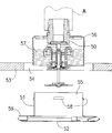
- the conshielded sprinkler head shown in FIG. 7 includes a sprinkler head 50 and a sprinkler head cover 51 attached to the sprinkler head.
- the sprinkler head 50 is installed behind the ceiling, and the sprinkler head 50 is covered with a sprinkler head cover 51 in a normal state so that only the cover plate 52 can be seen from the room.
- the sprinkler head cover 51 is attached to the sprinkler head 50 in the following procedure.
- a sprinkler head 50 is connected to the pipe A on the back of the ceiling, and only the tip portion of the sprinkler head 50 is exposed from a hole 54 formed in the ceiling board 53.
- a sprinkler head cover 51 is attached to the sprinkler head 50.
- the cylindrical portion 55 of the sprinkler head cover 51 is inserted into a cylindrical support cup 56 installed outside the sprinkler head 50.
- a spiral groove 57 is engraved on the side surface of the support cup 56, and a claw 58 that can be engaged with the spiral groove 57 is formed on the cylindrical portion 55 of the sprinkler head cover 51.
- the claw 58 can be elastically deformed, and when the cylinder portion 55 is moved to the pipe A side, the claw 58 is elastically deformed to overcome the spiral groove 57 and the cylinder portion 55 can be moved to the pipe A side.
- a sprinkler head cover mounting tool is used when performing the above-described sprinkler head cover mounting operation (see, for example, Patent Document 1).
- the surface of the sprinkler head cover can be prevented from becoming dirty with work gloves, and the sprinkler head cover can be prevented from being deformed by using an installation tool without the operator holding the sprinkler head cover directly. Can do.
- the sprinkler head accessory mounting tool of Patent Document 1 has a main body and a gripping rod, and has a main body shape that can accommodate a plurality of types of sprinkler head accessories.
- the shape of the sprinkler head accessory varies slightly from manufacturer to manufacturer, so preparing a body that fits those details can be quite a variety.
- the present invention is an attachment tool for attaching a sprinkler head accessory to a sprinkler head, and an object thereof is to provide a sprinkler head accessory attachment tool having high versatility.
- the first invention of the present application is a cylindrical body on which a sprinkler head accessory is placed, a gripping rod having one end inserted through the body and the other end serving as a gripping operation portion,
- the diameter of the first hole of the main body through which one end side of the gripping rod is inserted is smaller than the diameter of the second hole on the opposite side, and the sprinkler head accessory is on the second hole side.
- a sprinkler which is supported and has an inner flange between the first hole and the second hole, and has a holding member which contacts and holds the collar portion installed on one end side of the gripping rod with the inner flange of the main body.
- a sprinkler head accessory mounting tool is provided in which when the head accessory is attached to the sprinkler head, the collar portion is separated from the inner flange and the sprinkler head accessory can be moved to the outside of the main body at the collar portion.
- the sprinkler head accessory is accommodated and placed inside the main body. Thereby, even if the height of the cover plate which is an accessory of the sprinkler head is different, the cover plate can be supported by the inner peripheral surface of the main body.
- the grip rod is operated to move the sprinkler head accessory to the vicinity of the sprinkler head.
- the grip rod is moved in the direction of the sprinkler head with the center axis of the sprinkler head and the center axis of the sprinkler head accessory as the same axis, the sprinkler head accessory is pressed on one end side of the grip rod and attached to the sprinkler head.
- the second invention of the present application has a main body having a first hole in a plane and provided with an upright portion at an edge of the plane, and a sprinkler head placed on the plane of the main body.
- a pusher that moves the sprinkler head accessory away from the main body and has a tray on which the accessory is placed, and the end on the main body side is connected to the pusher, and is elongated at the end opposite to the end on the main body side
- a holding member that always keeps the pusher plate and the flat surface of the main body in contact with each other.
- the plate Provided is a sprinkler head accessory mounting tool that is movable in a direction away from a plane.
- the sprinkler head accessory since the sprinkler head accessory is placed on the push-up body installed inside the main body, the sprinkler head accessory is not restricted by the shape and size of the sprinkler head accessory, and further, The sprinkler head accessory is housed inside the standing part to prevent the sprinkler head accessory from falling off.
- the sprinkler head accessory is accommodated in the main body and is placed, so that it can be applied to various sprinkler head accessories. More specifically, for example, in the case of a structure in which the main body and the sprinkler head accessory are engaged and held, the engaging portion is specified according to the shape of the sprinkler head accessory. Since the head accessory is accommodated and placed, it can be prevented from being restricted by the shape and size of the sprinkler head accessory.
- the hole of the main body can be configured as a mortar shape whose diameter is increased from the side of the first hole through which the gripping rod is inserted toward the side of the second hole. According to this, even if there are a plurality of types of cover plate sizes, the cover plate can be supported in the main body.
- the central axis of the main body and the central axis of the sprinkler head accessory are formed. Can be supported in parallel.
- the hole of the main body can be configured to be capable of supporting a plurality of types of sprinkler head accessories having different contour shapes. According to this, for example, when the cover plate has a circular shape and a rectangular shape, it is possible to cope with both shapes.
- the holding member is an elastic body that urges the main body in the direction of the buttocks or the push-up body. It is also possible to form the elastic body by forming it on a part of the main body or the connecting material.
- the standing portion can be configured as a cylinder or a plurality of pins formed on the plane of the main body.
- this standing part is formed of a transparent member, the visibility of the internal sprinkler head accessory is improved.
- the sprinkler can be operated even if the gripping rod connected to the buttocks or push-up body is slightly tilted with respect to the ceiling board
- the head accessory can be attached to the sprinkler head. As a result, the work burden on the operator can be reduced.
- the sprinkler head accessory is limited by the size and shape of the sprinkler head accessory by placing the sprinkler head accessory on the inner peripheral surface of the hole of the main body or inside the standing part. It is possible to provide a sprinkler head accessory mounting tool that is difficult and versatile.
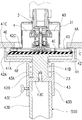
- Sectional drawing of the sprinkler head accessory attachment tool of 1st Embodiment The top view of the sprinkler head accessory attachment tool of FIG. Procedure for attaching the sprinkler head accessory to the sprinkler head. Sectional drawing of 2nd Embodiment. The top view of 3rd Embodiment. Sectional drawing of 4th Embodiment. Sectional drawing of the conventional sprinkler head and sprinkler head accessories. Sectional drawing of 5th Embodiment. Sectional drawing at the time of use of the sprinkler head accessory attachment tool of FIG. Sectional drawing of the modification of 5th Embodiment.
- a sprinkler head accessory mounting tool (hereinafter referred to as “mounting tool”) 100 includes a main body 1 and a gripping rod 2. If these are formed of a lightweight material such as resin or aluminum alloy, the burden of mounting work is reduced.
- the main body 1 has a cylindrical shape, and a gripping rod 2 is inserted on the lower end side in the figure.
- the lower end side of the hole 1A has a smaller diameter than the upper end side of the main body 1, and the hole 1A increases in diameter from the lower end side toward the upper end side.
- a sprinkler head cover 4 which is a sprinkler head accessory, is accommodated on the upper end side of the main body 1, and the cover plate 4 ⁇ / b> A of the sprinkler head cover 4 is supported on the inner surface on the upper end side of the main body 1. Since the hole 1A has a mortar shape, the cover plate 4A can be supported by the inner peripheral surface of the main body 1 even when the height and thickness of the cover plate 4A of the sprinkler head cover 4 are different.
- An inner flange 11 is formed at the lower end of the main body 1 so as to protrude inward, and a hole 12 is formed at the center thereof.
- the inner flange 11 locks the flange portion 21 formed at the upper end of the grip portion 2.
- the material of the main body 1 is formed of a member that can be seen through, the state of the internal sprinkler head cover 4 can be easily seen and the operability of the mounting tool 100 is improved.
- a transparent resin material can be used as the material of the main body 1.
- an opening or notch may be formed on the side surface of the main body 1 so that the internal sprinkler head cover 4 can be viewed.
- the grip rod 2 is a long and narrow bar, and the flange portion 21 at the upper end is locked to the inner flange 11 of the main body 1 as described above.
- a flange 22 is formed at a position slightly away from the flange 21, and a coil spring 23 is placed on the flange 22.
- the outer diameter of the gripping bar 2 is slightly smaller than the inner diameter of the hole 12 at the lower end of the main body 1, and there is a slight gap between the gripping bar 2 and the hole 12.
- the inner flange 11 of the main body 1 is placed on the upper end of the coil spring 23.
- the coil spring 23 has an action of urging the main body 1 toward the upper end side of the gripping rod 2 and maintaining a state where the flange portion 21 of the gripping rod 2 and the inner flange 11 of the main body 1 are locked. Therefore, the repulsive force of the coil spring 23 may be such a force that the spring 23 is not crushed in a state where the sprinkler head cover 4 is accommodated in the main body 1.
- the locking structure between the inner flange 11 of the main body 1 and the flange portion 21 of the gripping rod 2 functions as an anchoring portion that prevents the gripping rod 2 from coming off the main body 1.
- the coil spring 23 functions as a holding member that holds the gripping rod 2 on the lower end side of the main body 1.
- the lower end side of the grip rod 2 is a grip operation section 24 that is gripped and operated by an operator.
- the length of the gripping operation unit 24 is preferably 1 to 2 m when the worker performs installation work while standing on the floor. In addition to this, when the worker performs the mounting work on a scaffold such as a stepladder or work table, it is preferable to use a gripping operation unit 24 having a shorter length.
- the sprinkler head 3 is connected to a pipe on the back of the ceiling drawn by a two-dot chain line, and the lower part is disposed on the indoor side through the hole of the ceiling board C.
- the sprinkler head cover 4 is connected to the support cup 31 of the sprinkler head 3. First, the sprinkler head cover 4 is inserted into the main body 1 from the upper end side of the attachment tool 100.
- the cover plate 4 ⁇ / b> A of the sprinkler head cover 4 is placed on the inner peripheral surface of the main body 1.
- the cylinder portion 4B of the sprinkler head cover 4 is moved to the vicinity of the sprinkler head 3 by holding the grip operation portion 24 by hand. Subsequently, the position is adjusted so that the central axis of the cylindrical portion 4B and the central axis of the sprinkler head 3 are coaxial. At this time, if the main body 1 is made of a transparent material, the operator can easily grasp the positions of the sprinkler head 3 and the sprinkler head cover 4.
- the grip operation unit 24 is operated to move the sprinkler head cover 4 in the direction of the sprinkler head 3. Even when the main body 1 is slightly shaken by the movement, the sprinkler head cover 4 is housed inside the main body 1, so that the sprinkler head cover 4 can be prevented from falling off.
- the cylindrical portion 4B is inserted into the support cup 31. Then, the claw 4 ⁇ / b> C formed on the outer periphery of the cylindrical portion 4 ⁇ / b> B comes into contact with the groove 32 in the support cup 31.
- a mounting tool 200 according to the second embodiment shown in FIG. 4 has a stepped step portion 15 formed in the hole of the main body 1.
- the front surface 41 of the cover plate 4 ⁇ / b> A of the sprinkler head cover 4 accommodated in the main body 1 can be set perpendicular to the central axis of the main body 1.
- the sprinkler head cover 4 can be set in the main body 1 so that the central axis of the cylindrical portion 4B and the main body 1 are parallel to each other.
- the mounting tool 300 according to the third embodiment shown in FIG. 5 is capable of supporting a plurality of types of sprinkler head covers having different contour shapes of the holes 16 of the main body 1. Specifically, as shown in FIG. 5, the shape of the hole 16 is a contour shape when a circle and a rectangle are overlapped.
- the diameter of the hole 16 is increased from the lower end toward the upper end on the side where the gripping rod 2 is installed, and the inside of the main body 1 can be obtained even if the height and thickness of the cover plate 4A of the sprinkler head cover 4 are different as in the first embodiment.
- the cover plate 4A can be supported on the peripheral surface. In addition to this, the cover plate 4A can be used in a circular or rectangular shape.
- a mounting tool 400 according to the fourth embodiment shown in FIG. 6 uses a ring member as an anchoring portion for preventing the gripping rod 2 from coming off the main body 1.
- a ring member 25 such as a stop ring or an O-ring can be used on the side surface on the upper end side of the gripping rod 2. Since the outer diameter of the ring member 25 is slightly larger than the inner peripheral diameter of the inner flange 11 of the main body 1, the ring member 25 can be locked while the ring member 25 and the inner flange 11 are in contact with each other.
- step portion 11 ⁇ / b> A formed on the inner peripheral surface of the inner flange 11 and the ring member 25 are engaged, whereby the main body 1 and the gripping rod 2 maintain the engaged state.
- the push plate 26 is placed on the upper end of the gripping rod 2. As described in the first embodiment, when the gripping rod 2 is moved upward when the sprinkler head cover 4 is attached, the push plate 26 also moves upward and contacts the cover plate 4A. When the gripping rod 2 is moved further upward, the sprinkler head cover 4 can be pushed out of the main body 1 by the push plate 26.
- the upper end surface of the gripping bar 2 and the push plate 26 can be formed with an engagement structure 27 for preventing the push plate 26 from shifting or moving when the gripping bar 2 is operated.
- a hole 27 ⁇ / b> A was formed in the center of the upper end surface of the gripping rod 2, and a projection 27 ⁇ / b> B corresponding to the hole 27 ⁇ / b> A was formed at the center of the push plate 26. There is a slight gap between the hole 27A and the protrusion 27B.
- the ring member 25 also has a function as a holding member that holds the gripping rod 2 on the lower end side of the main body 2.
- an O-ring can be used as the ring member 25.
- the main body 1 and the gripping rod 2 can maintain the engaged state by the frictional resistance between the outer peripheral surface of the O-ring and the inner peripheral surface of the inner flange 11.
- the function as a mooring part and a holding member can be provided by installing a magnet instead of the ring member 25 and providing a member that can be connected to the inner peripheral surface of the inner flange 11 of the main body 1 by a magnetic force such as iron. .
- the mounting tool of the present invention can be applied to other than the sprinkler head accessory having the structure described above.
- the cover plate described in Japanese Patent Application Laid-Open No. 2005-270155 has a bowl shape, or the sealing plate described in Japanese Patent Application Laid-Open No. 2011-234911.
- the attachment tool 500 of 5th Embodiment shown to FIG. 8, 9 is comprised from the main body 41, the raising body 42, the connection material 43, and the holding member (spring 23).
- the attachment tool 500 of the fifth embodiment has a sufficiently large inner peripheral diameter of the main body 41, and can accommodate sprinkler head covers of various sizes and shapes. Thereby, the height dimension of the main body 41 can be suppressed as compared with the mounting tools of the first to fourth embodiments. Furthermore, a single attachment tool can be used for a variety of sprinkler head covers.
- the main body 41 has a hole 41B at the center of a disk-shaped plane 41A.
- the plane 41A corresponds to the inner flange 11 of the first embodiment.
- the lower surface of the flat surface 41 ⁇ / b> A is placed on the spring 23.
- a cylindrical upright portion 41C extended in a direction intersecting the plane 41A is provided at the periphery of the plane 41A. Since the tip of the standing portion 41C contacts the ceiling board C, it is possible to prevent the ceiling board C from being damaged if the corners are rounded.
- the size of the flat surface 41A is larger than the outer diameter of the sprinkler head cover 4, and the sprinkler head cover 4 is accommodated inside the standing portion 41C.
- the standing portion 41C is formed of a transparent member, the visibility of the internal sprinkler head cover 4 is improved. Or you may comprise the main body 41 with a transparent member.
- the push-up body 42 includes a dish 42A and a support post 42B.
- the dish 42 is placed on the flat surface 41A, and the outer diameter thereof is smaller than the inner diameter of the standing portion 41C.
- the dish 42 corresponds to the flange 21 provided at the upper end of the gripping rod 2 in the first embodiment.
- the sprinkler head cover 4 is placed on the tray 42A.
- a gap is provided between the plate 42 ⁇ / b> A and the standing portion 41 ⁇ / b> C, and the tilt of the plate 42 ⁇ / b> A is allowed with respect to the main body 41.
- a material softer than a metal such as sponge, rubber, or resin can be installed on the upper surface of the plate 42A.
- the inclination of the sprinkler head cover 4 can be absorbed by using a material having elasticity.
- sponge rubber 42C having elasticity is installed as an example. If the sponge rubber 42C is made of a soft material rather than a hard material, the cover plate 4A can be prevented from being deformed by an excessive force when the sprinkler head cover 4 is attached. The sprinkler head cover 4 is placed on the dish 42A via a sponge rubber 42C. Note that the material softer than the metal such as sponge, rubber, or resin can be applied to the end face of the flange portion 21 of the first to fourth embodiments.
- the support 42B is formed to hang downward from the center of the plate 42A.
- the support column 42B is inserted into the hole 41B, and a gap is provided between the outer peripheral surface of the support column 42B and the inner peripheral surface of the hole 41B so that the support column 42B can be slightly inclined.
- the standing portion 41C of the main body 41 is in contact with the ceiling board C, it is possible to prevent the attachment tool 500 from being damaged and to reduce the work burden on the operator by allowing the push-up body 42 to be slightly inclined.
- the lower end is fixedly connected to the connecting member 43 by a screw 42D.
- a screw 42D For the fixed connection with the connecting member 43, in addition to this, an adhesive or a male screw is formed at the lower end of the support post 42B, and a female screw is formed on the corresponding inner peripheral surface of the connecting member 43 and screwed together. Is also possible.
- the connecting member 43 has a cylindrical shape, and a flat surface 43C that partitions the inside of the connecting member 43 into an upper space 43A and a lower space 43B is provided.
- a support column 42B is inserted into the upper space 43A of the connecting member 43, and the flat surface 43C and the lower end surface of the support column 24B are fixedly connected as described above.
- a spring 23 is installed between the inner peripheral surface of the upper space 43A and the support column 42B. The spring 23 is installed between the flat surface 43C and the lower end surface of the main body 41, and urges the main body 41 upward in the figure.
- the flat surface 41A of the main body 41 and the plate 42A of the push-up body 42 are always kept in contact with each other.
- the repulsive force of the spring 23 can maintain the contact state between the flat surface 41A and the plate 42A when the sprinkler head cover 4 is placed on the plate 42A. Use a repulsive force that is not too strong.
- the spring 23 is housed inside the connecting member 43 and prevents dust from adhering to the spring 23 and damage due to external force.
- the pipe material 43D is inserted into the lower space 43B.
- the pipe material 43D corresponds to the grip operation unit 24 of the first embodiment.
- a female screw is formed on the inner periphery of the hole extending from the outer peripheral surface of the connecting member 43 to the lower space 43B.
- the screw 43E is screwed into the female screw from the outer peripheral side of the connecting member 43, and the pipe material is formed by the tip of the screw 43E.
- the pipe member 43D is fixedly connected to the connecting member 43 by pressing 43D.
- the procedure for attaching the sprinkler head cover 4 to the sprinkler head 3 using the attachment tool 500 is substantially the same as the attachment tool 100 of the first embodiment.
- the attachment state of the sprinkler head cover 4 is shown in FIG. In FIG. 9, the tip of the standing portion 41 ⁇ / b> C is in contact with the ceiling board C, and the dish 42 ⁇ / b> A moves away from the flat surface 41 ⁇ / b> A of the main body 41 toward the sprinkler head 3.
- the inclination of the dish 42A is absorbed by the gap 48 between the flat surface 41A of the main body 41 and the upper end of the connecting member 43, and the tip of the standing portion 41C of the main body 41 extends along the ceiling board C. Touched.
- the push-up body 42 and the main body 41 are prevented from interfering with the inclination of the mounting tool 500 due to the gap between the standing portion 41C and the plate 42A and the gap between the hole 41B and the column 42B.
- FIG. 10 shows a configuration in which the standing portion 41C is configured by a plurality of pins 45 installed on the periphery of the flat surface 41A.
- the number of pins 45 is six, but is not limited to this and may be three to eight.
- a plurality of notches may be formed in the standing portion 41C. This also reduces the contact area with the ceiling board C in the standing portion 41C so that the ceiling board C is not damaged. Further, when the sprinkler head cover 4 having a rectangular cover plate 4A is used, it is possible to install the cover plate by protruding the corners of the cover plate between the pins 45 or notches.
- a magnet 46 in the dish 42A as shown by a dotted line in FIG. If the legs 4E connecting the cylindrical portion 4B of the sprinkler head cover 4 and the cover plate 4A are made of iron, the magnets 46 and the legs 4E are attracted by the magnetic force, and the sprinkler head cover 4 can be prevented from falling off.
- the magnets 46 can be installed at locations corresponding to the legs 4E of the flat surface 41A, or more than the number of legs 4E.
- a ring 47 can be installed on the upper surface of the dish 42A.
- the mounting tool of the present invention to a sprinkler head cover in which the central portion of the cover plate 4A protrudes in a dome shape or a sealing plate described in Japanese Patent Application Laid-Open No. 2011-234911. Become.
- the attachment tool of the present invention can be applied to a wide variety of sprinkler head accessories because the sprinkler head accessory is placed on the main body.
- the sprinkler head accessory is housed inside the main unit to prevent the sprinkler head accessory from falling off the main unit when the main unit is close to the ceiling when installing the sprinkler head accessory. Work can be done smoothly.
Landscapes
- Health & Medical Sciences (AREA)
- Public Health (AREA)
- Business, Economics & Management (AREA)
- Emergency Management (AREA)
- Fire-Extinguishing By Fire Departments, And Fire-Extinguishing Equipment And Control Thereof (AREA)
Abstract
Le problème selon l'invention est de proposer un outil de fixation d'un accessoire pour tête de sprinkler permettant d'installer un accessoire pour tête de sprinkler sur une tête de sprinkler, ledit outil étant hautement adaptable. La solution selon l'invention consiste en un outil de fixation d'un accessoire pour tête de sprinkler comprenant : un corps principal (1) en forme de tube et sur lequel un accessoire pour tête de sprinkler (4) est chargé ; et une tige de préhension (2), dont une extrémité traverse l'intérieur du corps principal (1), tandis que l'autre sert de pièce de manipulation permettant la préhension (24). Le diamètre d'un premier trou (12) du corps principal est plus petit que le diamètre d'un second trou (1A) situé du côté opposé au premier. L'accessoire pour tête de sprinkler (4) est supporté du côté du second trou (1A) et une bride située du côté intérieur (11) est prévue entre le premier trou (12) et le second trou (1A). Un élément de retenue (23) est en outre prévu pour retenir une partie de bride (21) de la tige de préhension (2), de manière à ce qu'elle soit en contact avec la bride située du côté intérieur (11) du corps principal. Lors du montage de l'accessoire pour tête de sprinkler (4) sur la tête de sprinkler (3), la pièce de bride (21) se sépare de la bride située du côté intérieur (11), ce qui permet à l'accessoire pour tête de sprinkler (4) de se déplacer à l'extérieur du corps principal (1).
Applications Claiming Priority (2)
| Application Number | Priority Date | Filing Date | Title |
|---|---|---|---|
| PCT/JP2014/062304 WO2015170379A1 (fr) | 2014-05-08 | 2014-05-08 | Outil de fixation d'un accessoire pour tête de sprinkler |
| JPPCT/JP2014/062304 | 2014-05-08 |
Publications (1)
| Publication Number | Publication Date |
|---|---|
| WO2015170731A1 true WO2015170731A1 (fr) | 2015-11-12 |
Family
ID=54392249
Family Applications (2)
| Application Number | Title | Priority Date | Filing Date |
|---|---|---|---|
| PCT/JP2014/062304 Ceased WO2015170379A1 (fr) | 2014-05-08 | 2014-05-08 | Outil de fixation d'un accessoire pour tête de sprinkler |
| PCT/JP2015/063264 Ceased WO2015170731A1 (fr) | 2014-05-08 | 2015-05-08 | Outil de fixation d'un accessoire pour tête de sprinkler |
Family Applications Before (1)
| Application Number | Title | Priority Date | Filing Date |
|---|---|---|---|
| PCT/JP2014/062304 Ceased WO2015170379A1 (fr) | 2014-05-08 | 2014-05-08 | Outil de fixation d'un accessoire pour tête de sprinkler |
Country Status (1)
| Country | Link |
|---|---|
| WO (2) | WO2015170379A1 (fr) |
Citations (7)
| Publication number | Priority date | Publication date | Assignee | Title |
|---|---|---|---|---|
| JPS5574984U (fr) * | 1978-11-14 | 1980-05-23 | ||
| JPS596286U (ja) * | 1982-06-30 | 1984-01-14 | 鈴木 豊重 | 火災報知装置用感知器の脱着器 |
| JPH02143688U (fr) * | 1989-04-25 | 1990-12-05 | ||
| JP2003311643A (ja) * | 2002-04-23 | 2003-11-05 | Kyudenko Corp | シーリングプレート取付け工具 |
| JP2004272389A (ja) * | 2003-03-05 | 2004-09-30 | Matsushita Electric Works Ltd | 感知器着脱工具 |
| JP2012166081A (ja) * | 2012-06-12 | 2012-09-06 | Senju Sprinkler Kk | スプリンクラーヘッド付属品着脱工具 |
| WO2013125341A1 (fr) * | 2012-02-22 | 2013-08-29 | 千住スプリンクラー株式会社 | Gabarit de montage d'une fixation d'une tête d'arrosage |
Family Cites Families (4)
| Publication number | Priority date | Publication date | Assignee | Title |
|---|---|---|---|---|
| JPS6063367U (ja) * | 1983-10-07 | 1985-05-04 | 千住金属工業株式会社 | シ−リンングプレ−ト取付装置 |
| US4795211A (en) * | 1987-12-11 | 1989-01-03 | Cine Coasters, Inc. | Universal container holder |
| JP3805071B2 (ja) * | 1997-07-25 | 2006-08-02 | 能美防災株式会社 | 火災感知器の着脱器 |
| JP5061174B2 (ja) * | 2009-12-10 | 2012-10-31 | 千住スプリンクラー株式会社 | スプリンクラーヘッド付属品着脱工具 |
-
2014
- 2014-05-08 WO PCT/JP2014/062304 patent/WO2015170379A1/fr not_active Ceased
-
2015
- 2015-05-08 WO PCT/JP2015/063264 patent/WO2015170731A1/fr not_active Ceased
Patent Citations (7)
| Publication number | Priority date | Publication date | Assignee | Title |
|---|---|---|---|---|
| JPS5574984U (fr) * | 1978-11-14 | 1980-05-23 | ||
| JPS596286U (ja) * | 1982-06-30 | 1984-01-14 | 鈴木 豊重 | 火災報知装置用感知器の脱着器 |
| JPH02143688U (fr) * | 1989-04-25 | 1990-12-05 | ||
| JP2003311643A (ja) * | 2002-04-23 | 2003-11-05 | Kyudenko Corp | シーリングプレート取付け工具 |
| JP2004272389A (ja) * | 2003-03-05 | 2004-09-30 | Matsushita Electric Works Ltd | 感知器着脱工具 |
| WO2013125341A1 (fr) * | 2012-02-22 | 2013-08-29 | 千住スプリンクラー株式会社 | Gabarit de montage d'une fixation d'une tête d'arrosage |
| JP2012166081A (ja) * | 2012-06-12 | 2012-09-06 | Senju Sprinkler Kk | スプリンクラーヘッド付属品着脱工具 |
Also Published As
| Publication number | Publication date |
|---|---|
| WO2015170379A1 (fr) | 2015-11-12 |
Similar Documents
| Publication | Publication Date | Title |
|---|---|---|
| US9267518B2 (en) | Holder mechanism | |
| US8096516B2 (en) | Tool storage device | |
| JP5061174B2 (ja) | スプリンクラーヘッド付属品着脱工具 | |
| WO2015170731A1 (fr) | Outil de fixation d'un accessoire pour tête de sprinkler | |
| CN108972487B (zh) | 一种智能制造业便于对零部件进行防护的放置架 | |
| JP6063441B2 (ja) | スプリンクラーヘッド付属品取付工具 | |
| JP2016048082A (ja) | 吸盤 | |
| JP6165220B2 (ja) | 係合具 | |
| JP2016087773A (ja) | ソケットレンチ及びソケットレンチアダプター。 | |
| JP6553842B2 (ja) | ロボットハンドの爪交換方法及び爪交換システム | |
| JP3187796U (ja) | スプリンクラーヘッド付属品着脱工具 | |
| JP2012024308A (ja) | スプリンクラーヘッド付属品装着工具 | |
| JP2012166081A (ja) | スプリンクラーヘッド付属品着脱工具 | |
| JP2012024308A5 (fr) | ||
| JP3185691U (ja) | スプリンクラーヘッド付属品装着工具 | |
| GB2552578A (en) | Socket holding frame | |
| JP3155095U (ja) | 携帯型吊下げ具 | |
| JP4638387B2 (ja) | 照明器具の壁面取付構造 | |
| JP3217342U (ja) | スプリンクラーヘッド付属品取付工具 | |
| JP3139262U (ja) | 保持具 | |
| WO2015064224A1 (fr) | Outil de fixation de raccord de tête de sprinkler | |
| JP2018084269A (ja) | 支持具と脱着操作治具及び支持具取付け方法 | |
| TWM517069U (zh) | 棘輪扳手結構 | |
| JP3191630U (ja) | キャップホルダー | |
| JP4855907B2 (ja) | 保持具 |
Legal Events
| Date | Code | Title | Description |
|---|---|---|---|
| 121 | Ep: the epo has been informed by wipo that ep was designated in this application |
Ref document number: 15789049 Country of ref document: EP Kind code of ref document: A1 |
|
| NENP | Non-entry into the national phase |
Ref country code: DE |
|
| NENP | Non-entry into the national phase |
Ref country code: JP |
|
| 122 | Ep: pct application non-entry in european phase |
Ref document number: 15789049 Country of ref document: EP Kind code of ref document: A1 |