WO2015170944A1 - Mécanismes concernant une attribution de ressources, découverte et signalisation dans des systèmes d2d - Google Patents
Mécanismes concernant une attribution de ressources, découverte et signalisation dans des systèmes d2d Download PDFInfo
- Publication number
- WO2015170944A1 WO2015170944A1 PCT/KR2015/004693 KR2015004693W WO2015170944A1 WO 2015170944 A1 WO2015170944 A1 WO 2015170944A1 KR 2015004693 W KR2015004693 W KR 2015004693W WO 2015170944 A1 WO2015170944 A1 WO 2015170944A1
- Authority
- WO
- WIPO (PCT)
- Prior art keywords
- resource
- dru
- data
- rpt
- transmission
- Prior art date
- Legal status (The legal status is an assumption and is not a legal conclusion. Google has not performed a legal analysis and makes no representation as to the accuracy of the status listed.)
- Ceased
Links
Images




Classifications
-
- H—ELECTRICITY
- H04—ELECTRIC COMMUNICATION TECHNIQUE
- H04W—WIRELESS COMMUNICATION NETWORKS
- H04W72/00—Local resource management
- H04W72/20—Control channels or signalling for resource management
-
- H—ELECTRICITY
- H04—ELECTRIC COMMUNICATION TECHNIQUE
- H04L—TRANSMISSION OF DIGITAL INFORMATION, e.g. TELEGRAPHIC COMMUNICATION
- H04L5/00—Arrangements affording multiple use of the transmission path
- H04L5/003—Arrangements for allocating sub-channels of the transmission path
- H04L5/0044—Allocation of payload; Allocation of data channels, e.g. PDSCH or PUSCH
-
- H—ELECTRICITY
- H04—ELECTRIC COMMUNICATION TECHNIQUE
- H04L—TRANSMISSION OF DIGITAL INFORMATION, e.g. TELEGRAPHIC COMMUNICATION
- H04L5/00—Arrangements affording multiple use of the transmission path
- H04L5/0001—Arrangements for dividing the transmission path
- H04L5/0003—Two-dimensional division
- H04L5/0005—Time-frequency
-
- H—ELECTRICITY
- H04—ELECTRIC COMMUNICATION TECHNIQUE
- H04W—WIRELESS COMMUNICATION NETWORKS
- H04W8/00—Network data management
- H04W8/005—Discovery of network devices, e.g. terminals
-
- H—ELECTRICITY
- H04—ELECTRIC COMMUNICATION TECHNIQUE
- H04W—WIRELESS COMMUNICATION NETWORKS
- H04W72/00—Local resource management
- H04W72/20—Control channels or signalling for resource management
- H04W72/23—Control channels or signalling for resource management in the downlink direction of a wireless link, i.e. towards a terminal
-
- H—ELECTRICITY
- H04—ELECTRIC COMMUNICATION TECHNIQUE
- H04W—WIRELESS COMMUNICATION NETWORKS
- H04W76/00—Connection management
- H04W76/10—Connection setup
- H04W76/14—Direct-mode setup
-
- H—ELECTRICITY
- H04—ELECTRIC COMMUNICATION TECHNIQUE
- H04W—WIRELESS COMMUNICATION NETWORKS
- H04W88/00—Devices specially adapted for wireless communication networks, e.g. terminals, base stations or access point devices
- H04W88/02—Terminal devices
-
- H—ELECTRICITY
- H04—ELECTRIC COMMUNICATION TECHNIQUE
- H04W—WIRELESS COMMUNICATION NETWORKS
- H04W88/00—Devices specially adapted for wireless communication networks, e.g. terminals, base stations or access point devices
- H04W88/08—Access point devices
Definitions
- the present disclosure relates to resource allocation, discovery, and signaling schemes in device-to-device (D2D) networks. More particularly, the present disclosure relates to resource allocation, discovery, and signaling schemes in Long Term Evolution (LTE) network-based D2D systems.
- LTE Long Term Evolution
- the 5G or pre-5G communication system is also called a ‘Beyond 4G Network’ or a ‘Post LTE System’.
- the 5G communication system is considered to be implemented in higher frequency (mmWave) bands, e.g., 60GHz bands, so as to accomplish higher data rates.
- mmWave e.g., 60GHz bands
- MIMO massive multiple-input multiple-output
- FD-MIMO Full Dimensional MIMO
- array antenna an analog beam forming, large scale antenna techniques are discussed in 5G communication systems.
- RANs Cloud Radio Access Networks
- D2D device-to-device
- wireless backhaul moving network
- cooperative communication Coordinated Multi-Points (CoMP), reception-end interference cancellation and the like.
- CoMP Coordinated Multi-Points
- Hybrid FSK and QAM Modulation FQAM
- SWSC sliding window superposition coding
- ACM advanced coding modulation
- FBMC filter bank multi carrier
- NOMA non-orthogonal multiple access
- SCMA sparse code multiple access
- an evolved Node B dynamically allocates resources to a user equipment (UE) on a per-sub-frame basis. If semi-persistent scheduling (SPS) is activated, the UE is granted to periodically use resources allocated based on predetermined settings until the SPS is released.
- SPS semi-persistent scheduling
- FIG. 1 is a view illustrating an example of an LTE network-based device-to-device (D2D) system according to the related art.
- D2D device-to-device
- the LTE network-based D2D system may come in two communication modes.
- the two communication modes include in-coverage D2D communication mode and out-of-coverage D2D communication mode.
- UEs 102, 104 and 106 are in-coverage mode UEs, and UEs 112 and 114 are out-of-coverage mode UEs.
- UEs 108 and 110 are partial in-coverage mode UEs.
- in-coverage mode the resources used for the UE 102 to transmit data and control information are directly scheduled by an eNB 100.
- out-of-coverage mode the resources used for the UE 112 to transmit data and control information are selected by the UE 112 from a resource pool.
- FIG. 2 is a view illustrating an example of a structure of a communication frame in a D2D communication system according to the related art.
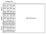
- a D2D frame 200 may be divided into a scheduling assignment (SA) region 202 and a data region 204.
- the SA region 202 is a region where control information is transmitted and may contain multiple control units (resource units used for controlling).
- the UE may transmit an SA indicating a resource to be used for transmission in the data region 204.
- the data region 204 typically has a length of tens of sub-frames or more. For example, the data region 204 may be 40ms to 160ms long.
- the resource allocation scheme in LTE cannot be directly applied to D2D communication. Accordingly, a need exists for designing a resource allocation mechanism and signaling for LTE network-based D2D systems.
- an aspect of the present disclosure is to provide a resource allocation scheme and a signaling scheme corresponding to the resource allocation scheme based on the characteristics of device-to-device (D2D) communication.
- D2D device-to-device
- Another aspect of the present disclosure is to provide a flexible resource allocation method for device discovery in D2D systems to efficiently address problems with, e.g., half duplex and in-band emission.
- a method for performing D2D communication by an in-coverage user equipment (UE) in a cellular communication system includes receiving a scheduling grant through a downlink control channel from a base station evolved Node B (eNB) and transmitting a scheduling assignment (SA) message in an SA region of a D2D communication frame and data in a data region of the D2D communication frame, based on the scheduling grant, wherein the scheduling grant indicates a resource pattern for transmission (RPT) corresponding to a set of resource units or a subset of a resource unit in a time domain and a frequency domain that is used for transmission of the data.
- RTT resource pattern for transmission
- a method for performing D2D communication by an out-of-coverage UE in a cellular communication system includes monitoring an SA region and a data region of a D2D communication frame based on a preset resource pool, determining an unused SA unit and RPT respectively in the SA region and the data region, and transmitting an SA message and data respectively in the determined unused SA unit and RPT, wherein the SA message indicates the RPT corresponding to a set of resource units or a subset of a resource unit in a time domain and a frequency domain that is used for transmission of the data.
- an in-coverage UE performing D2D communication in a cellular communication system includes a transceiver configured to receive a scheduling grant through a downlink control channel from an eNB and to transmit an SA message in an SA region of a D2D communication frame and data in a data region of the D2D communication frame, based on the scheduling grant, wherein the scheduling grant indicates an RPT corresponding to a set of resource units or a subset of a resource unit in a time domain and a frequency domain that is used for transmission of the data.
- an out-of-coverage UE performing D2D communication in a cellular communication system includes a controller configured to monitor an SA region and a data region of a D2D communication frame based on a preset resource pool, and to determine an unused SA unit and RPT respectively in the SA region and the data region, and a transceiver configured to transmit an SA message and data respectively in the determined unused SA unit and RPT, wherein the SA message indicates a RPT corresponding to a set of resource units or a subset of a resource unit in a time domain and a frequency domain that is used for transmission of the data.
- a method for performing D2D discovery by a UE in a cellular communication system includes receiving, from an eNB, discovery resource pool information and at least one of linkage pattern information on a discovery resource unit (DRU) pair, information on a count of transmission of discovery messages in a unit discovery period, and information on a hopping interval of the DRU pair, obtaining information on a resource allocated for transmission of the discovery messages based on the received at least one information, and transmitting the discovery messages in M discovery periods based on at least one of a rule of DRU hopping and a rule of DRU pair hopping, wherein the DRU hopping is used in each of the M discovery periods, and the DRU pair hopping is used once in the M discovery periods.
- DRU discovery resource unit
- FIG. 1 is a view illustrating an example of a Long Term Evolution (LTE) network-based device-to-device (D2D) system according to the related art;
- LTE Long Term Evolution
- D2D device-to-device
- FIG. 2 is a view illustrating an example of a structure of a communication frame in a D2D communication system according to the related art
- FIG. 3 is a view illustrating an example of a resource pattern design according to an embodiment of the present disclosure
- FIG. 4 is a view illustrating an example of semi-explicit signaling resource allocation according to an embodiment of the present disclosure
- FIG. 5 is a view illustrating an example of a resource allocation and signaling procedure in a D2D system according to an embodiment of the present disclosure
- FIG. 6 is a view illustrating an example of a method for obtaining and transmitting scheduling assignment (SA)/resource pattern for transmission (RPT) information by an in-coverage mode D2D transmission user equipment (UE) according to an embodiment of the present disclosure;
- SA scheduling assignment
- RPT resource pattern for transmission
- FIG. 7 is a view illustrating an example of a method for obtaining and transmitting SA/RPT information by an out-of-coverage D2D transmission UE with the aid of an in-coverage UE according to an embodiment of the present disclosure
- FIG. 8 is a view illustrating an example of an operation of a D2D reception UE according to an embodiment of the present disclosure
- FIG. 9 is a view illustrating an example of resource allocation to address a half-duplex issue according to an embodiment of the present disclosure.
- FIG. 10 is a view illustrating an example of a configuration of a D2D UE according to an embodiment of the present disclosure
- FIG. 11 is a view illustrating an example of a D2D system enabling discovery and communication between UEs according to an embodiment of the present disclosure
- FIG. 12 is a view illustrating an example of a D2D discovery frame structure in a D2D system according to an embodiment of the present disclosure
- FIG. 14 is a view illustrating examples of SA patterns to avoid half-duplex limitation according to an embodiment of the present disclosure
- FIGS. 15A and 15B are views illustrating an example of a D2D discovery resource hopping method according to an embodiment of the present disclosure
- FIG. 16 is a view illustrating an example of a D2D discovery resource hopping method in case only discovery resource unit (DRU) pair hopping applies according to an embodiment of the present disclosure
- FIG. 17 is a view illustrating an example of a periodic shuffling method to address hidden UE issues according to an embodiment of the present disclosure
- FIG. 20 is a view illustrating an example of a DRU pair linkage pattern applied to SA transmission according to an embodiment of the present disclosure
- FIG. 21 is a view illustrating an example of D2D discovery resource hopping to which a hopping pattern applies according to an embodiment of the present disclosure
- FIG. 22 is a view illustrating an example of a procedure in which a UE receives a resource allocation from an evolved Node B (eNB) and transmits an initial discovery message according to an embodiment of the present disclosure
- eNB evolved Node B
- FIG. 23 is a view illustrating an example of a discovery resource access procedure when a UE transmits a discovery message in a next discovery period according to an embodiment of the present disclosure
- FIG. 24 is a view illustrating an example of d discovery message receiving procedure by a UE according to an embodiment of the present disclosure
- FIGS. 25A, 25B, 25C, and 25D are views illustrating examples of linkage between two SAs used by one UE according to various embodiments of the present disclosure
- FIG. 27 is a view illustrating an example of a method in which an in-coverage UE transmitter operates in mode 1 and mode 2 according to an embodiment of the present disclosure
- FIG. 28 is a view illustrating an example of a method in which an in-coverage UE receiver operates in different modes of an SA pool and a data pool according to an embodiment of the present disclosure
- FIG. 29 is a view illustrating an example of a procedure in which an in-coverage UE transmitter obtains time domain RPT (T-RPT) bitmap repetition information when the number of transmission medium access control (MAC) protocol data units (PDUs) is set by a system information block (SIB) for mode 1 according to an embodiment of the present disclosure;
- T-RPT time domain RPT
- MAC transmission medium access control
- SIB system information block
- FIG. 30 is a view illustrating an example of a procedure in which an in-coverage UE receiver obtains T-RPT bitmap repetition information when the number of transmission MAC PDUs is set by an SIB for mode 1 according to an embodiment of the present disclosure.
- FIG. 31 is a view illustrating an example of an operation of a UE in case the UE receives a scheduling grant but has no data to transmit according to an embodiment of the present disclosure.
- a base station is an entity communicating with a user equipment (UE) and may be denoted as BS, Node B (NB), evolved Node B (eNB), or Access Point (AP).
- BS Node B
- eNB evolved Node B
- AP Access Point
- the user equipment is an entity communicating with a BS, and may be denoted as UE, mobile station (MS), mobile equipment (ME), device, or terminal.
- UE mobile station
- ME mobile equipment
- the device-to-device (D2D) frame may be transmitted through uplink (UL) resources of Long Term Evolution (LTE) resources.
- UL uplink
- LTE Long Term Evolution
- D2D communication in the LTE network aims to enable broadcast communication between UEs.
- the UE in D2D communication is not designated in resource allocation or not explicitly controlled. Transmission of control information and data between UEs is one-way transmission with no feedback for data broadcasting.
- FIG. 11 is a view illustrating an example of a D2D system enabling discovery and communication between UEs according to an embodiment of the present disclosure.
- a material characteristic of the D2D system is that neighbor UEs (i.e., D2D devices) 1105 may discover each other with the aid of an eNB 1100 or even without the aid of the eNB 1100.
- the UE 1105 may discover a UE 1115 in the same cell as well as a UE 1110 in a neighbor cell.
- FIG. 12 is a view illustrating an example of a D2D discovery frame structure in a D2D system according to an embodiment of the present disclosure.
- a particular period 1200 with an arbitrary length in each cell may be periodically allocated for D2D discovery.
- one discovery period 1200 may include multiple discovery resource units (DRUs) 1210.
- DRUs discovery resource units
- One DRU 1210 may take up one transmission time interval (TTI) 1215 (e.g., one sub-frame) in the time domain and one or more resource blocks 1220 in the frequency domain.
- TTI transmission time interval
- One DRU 1210 is generally used in transmitting one UE discovery message, and accordingly, the size of one DRU may be influenced by the size of the discovery message.
- each discovery period may have a total of (Nt*Nf) DRUs, and each DRU may be denoted in DRU ⁇ nt, nf>, where nt is a TTI index (or time index) and nf is a frequency index.
- the eNB may allocate DRUs used for a particular UE in each discovery period. Or, the UE may randomly select DRUs for transmitting a discovery message.
- a D2D resource pool for transmission of control information and data of the D2D UE 102 may be scheduled by the eNB 100 through a broadcast channel (BCH).
- BCH broadcast channel
- the eNB 100 transmits a D2D_Grant (i.e., a scheduling grant) for a scheduling assignment (SA) and/or data to the D2D UE 102.
- the D2D UE 102 may transmit an SA in an SA resource allocated by the eNB 100 or transmit data in a data transmission resource allocated by the eNB 100.
- the D2D UEs 104 and 106 read the SA in the SA region 202 and check if the target identifier (ID) matches the D2D UEs. If the target ID of the SA matches the D2D UEs 104 and 106, the D2D UEs 104 and 106 may implicitly or explicitly receive data from the resource linked to the SA.
- ID target identifier
- a D2D resource pool for control information and data may be preset.
- the D2D UE 112 selects an SA and/or data resource for transmission to another D2D UE 114 based on a monitoring SA (or data) resource pool.
- the D2D UE 112 may transmit an SA with an intended target ID in the selected SA resource or transmit data in the selected data resource.
- the other D2D UE 114 checks the SA in the SA region 202 for whether there is a target ID matching the D2D UE. If the target ID of the SA matches the other D2D UE 114, the other D2D UE 114 may implicitly or explicitly receive data from the resource linked to the SA.
- the overall procedure by a partial in-coverage UE in case an SA is not scrambled with a target ID is described with reference to FIGS. 1 and 2, as follows.
- the scrambling may be, e.g., that an SA is cyclic redundancy check (CRC)-masked with the target ID.
- CRC cyclic redundancy check
- data as well as the SA may be scrambled and transferred.
- a D2D resource pool for transmission of control information and data of the first D2D UE 108 may be scheduled by the eNB 100 through a BCH.
- the eNB 100 transmits a D2D_Grant for an SA and/or data to the first D2D UE 108.
- the first D2D UE 108 may transmit an SA with an intended target ID in an SA resource allocated by the eNB 100 or transmit data in a data transmission resource allocated by the eNB 100.
- the second D2D UE 110 decodes the SA signal from the first D2D UE 108 and selects an unused SA and data resource for a next SA period.
- the second D2D UE 110 may transmit an SA with an intended target ID in the selected SA resource or transmit data in the selected data resource.
- Another neighbor D2D UE checks if the target ID of the SA matches the D2D UE, and if the SA matches the D2D UE, may implicitly or explicitly receive data in the resource linked to the SA.
- a D2D resource pool for transmission of control information and data of the first D2D UE 108 may be scheduled by the eNB 100 through a BCH.
- the eNB 100 transmits a D2D_Grant for an SA and/or data to the first D2D UE 108.
- the first D2D UE 108 may transmit an SA with an intended target ID in an SA resource allocated by the eNB 100 or transmit data in a data transmission resource allocated by the eNB 100.
- the second D2D UE 110 Since the SA is scrambled with the target ID, the second D2D UE 110 cannot decode the SA and merely senses a signal from the first D2D UE 108 to select an unused SA and data resource for a next SA period.
- the second D2D UE 110 may transmit an SA with an intended target ID in the selected SA resource or transmit data in the selected data resource.
- Another neighbor D2D UE checks if the target ID of the SA matches the D2D UE, and if the SA matches the D2D UE, may implicitly receive data in the resource linked to the SA.
- a D2D resource pool for transmission of control information and data of the first D2D UE 108 may be scheduled by the eNB 100 through a BCH.
- the eNB 100 transmits a D2D_Grant for an SA and/or data to the first D2D UE 108.
- the first D2D UE 108 may transmit an SA with an intended target ID in an SA resource allocated by the eNB 100 or transmit data in a data transmission resource allocated by the eNB 100.
- the second D2D UE 110 cannot decode the SA from the first D2D UE 108 and merely senses a signal from the first D2D UE 108 to select an unused SA and data resource for a next SA period.
- the second D2D UE 110 may transmit an SA with an intended target ID in the selected SA resource or transmit data in the selected data resource.
- the second D2D UE 110 may decode the SA signal from the first D2D UE 108 and selects an unused SA and data resource for a next SA period.
- the second D2D UE 110 may transmit an SA with an intended target ID in the selected SA resource or transmit data in the selected data resource.
- Another neighbor D2D UE checks if the target ID of the SA matches the D2D UE, and if the SA matches the D2D UE, may implicitly or explicitly receive data in the resource linked to the SA.
- the linkage between the SA and data may be implicit.
- the D2D UE may have an SA-data linkage table for scrambled SA reception. Based on the SA-data linkage table for scrambled SA reception, the D2D UE may be aware of data resources even without decoding the SA when sensing the SA and the location of the SA resource.
- the SA signal may include one-bit information to indicate whether to be a scrambled SA or not. The D2D UE may be aware of the implicit or explicit mapping policy using the one-bit information and exactly discover unused data resources.
- the UE may operate in two modes (i.e., mode 1 or mode 2).
- mode 1 the eNB schedules corresponding resources for data transmission in the UE.
- mode 2 each UE selects resources in a resource pool for data transmission.
- the in-coverage UE may operate in the two modes both. That is, the in-coverage UE, if allocated resources by the eNB, may operate in mode 1, or if selecting resources on its own, operate in mode 2.
- the out-of-coverage UE cannot communicate with the eNB, and thus, the out-of-coverage UE may operate only in mode 2.
- the out-of-coverage UE itself may select resources from a preset resource pool for data transmission.
- the UEs 102, 104, and 106 may operate in mode 1 or mode 2, but the UEs 112, 114, 108, and 110 may operate only in mode 2.
- FIG. 3 is a view illustrating an example of a resource pattern design according to an embodiment of the present disclosure.
- One RPT may include a set (collection) of resource units in the time domain and frequency domain.
- One RPT may correspond to one resource set.
- the resource set may have consecutive resource units in the time domain, and the resource units on different time units may have different frequency positions from each other.
- One RPT may correspond only to a subset of the resource set.
- the subset may be a set of periodic resource units in the time domain or a set of consecutive resource units in multiple time units.
- the RPT design may include various patterns supporting different types of traffic, such as voice traffic, burst traffic, file transfer protocol (FTP) traffic, or video streams.
- traffic such as voice traffic, burst traffic, file transfer protocol (FTP) traffic, or video streams.
- FTP file transfer protocol
- One resource set starts from one resource unit of a first time unit.
- Resource units in subsequent time units may be derived (determined) by a particular rule.
- the particular rule may be a predetermined frequency hopping pattern.
- a subset of one resource set may be derived by a time hopping rule.
- one resource unit may be a resource block (RB) or an RB pair.
- the RB may correspond to a time unit that is one time slot, and the RB pair may correspond to a time unit of one sub-frame.
- Two resource sets may start from a resource unit 350 with index #1 and a resource unit 360 with index #6 in the first time unit, and resource units 352, 362, 354, and 364 in a subsequent time unit may be determined based on a predetermined frequency hopping pattern.
- Each resource set may be divided into four resource subsets based on a predetermined time hopping rule.
- resource units to be used may be explicitly indicated to generate a new RPT.
- one resource unit may be one RB, one RB pair, or multiple RB pairs. Accordingly, the information of resource set may be jointly determined by the size of resource unit, frequency index of resource unit, and frequency hopping rule. For time domain RPTs in one resource set, each RPT may be represented with a transmission period, repetition count, and subset index.
- the transmission period defines an interval between transmissions for multiple medium access control (MAC) protocol data unit (PDUs), the repetition count is the number of times that transmission is performed per MAC PDU, and each transmission per MAC PDU may be a repeated or duplicate version of the initial transmission.
- the subset index is a predefined index to indicate resources to be used.
- the resource allocation signaling method may include 1) implicit signaling, 2) explicit signaling, and 3) semi-explicit signaling.
- each SA may be directly linked to one or more resource patterns.
- the rule of linkage may be predetermined or preset by the network.
- a possible linkage rule is that each SA is linked to a predetermined RPT (i.e., resource subset). If there are LxK SAs (in case the SA region is present over L time units and K frequency units), the SA with time unit l and frequency index k, SA(l,k), may be linked to the lth subset of the kth resource set (i.e., predetermined RPT #k-l).
- SA1 340 is linked to a predetermined RPT #1-1 (subset 1 of resource set 1), and SA2 342 is linked to a predetermined RPT #1-2 (subset 2 of resource set 1).
- the number (L) of time slots of the SA region may be the same as the number of subsets of one resource set (i.e., the number of resource patterns of one resource set).
- the eNB signals a scheduling grant to the UE, only indicating the index of the SA is required, and the resource pattern may be implicitly linked to the UE.
- the index of the SA may be indicated based on a predetermined indexing rule.
- the indexing rule is to number SA indexes in order or to combine frequency indexes and time indexes.
- resources to be used are explicitly indicated, and resources for SAs and data may be distinctly indicated. In this case, there is no linkage between the SA and RPT.
- SA1 340 may be indicated for SA transmission
- predefined RPT #6-1 may be indicated for data transmission.
- a new RPT to be used may be explicitly indicated instead of indicating predefined resource patterns by the eNB.
- a limited number of SAs may be linked to a limited number of resource patterns.
- One possible method is to, in case predetermined RPTs are used, limit SA (l,k) with time unit l in frequency index k to be used only for RPTs (e.g., RPT #k-n ( )) in resource set k.
- RPTs e.g., RPT #k-n ( )
- SA1 340, SA2 342, SA3 344, and SA4 346 are limited to be used only for the RPTs of the first resource set.
- the UE may be aware of available RPTs. Additional information regarding exact resource usage may be indicated in the data grant.
- the semi-explicitly signaling method may achieve more flexible resource indication than explicitly signaling by using the same number of bits, and this is why it is needed to indicate resource usage from a limited number of resource patterns rather than all the resource patterns.
- FIG. 4 is a view illustrating an example of semi-explicit signaling resource allocation according to an embodiment of the present disclosure.
- FIG. 4 an example of semi-explicitly signaling is shown.
- Two SAs 410 and 420 in the upper end of the SA region are linked to a resource set #1 (412, 422).
- a resource set #1 (412, 422).
- one SA 400 corresponding to the resource set 402 is granted.
- two SAs 410 and 420 are granted, and respectively corresponds to a resource subset #1-1 (412) and resource subset #1-2 (422).
- Another possible semi-explicitly signaling method is to limit SA(l,k) in time unit l and frequency index k to be used only for RPTs (i.e., predetermined RPT #m-l ( )) corresponding to subset l of each resource set.
- the above-described signaling method is to explicitly or implicitly indicate the RPT subset index for data transmission in the time domain, together with a period value and a repetition value.
- a bitmap-based method may be used to explicitly indicate a resource subset to be used.
- a bitmap (N,k) has a length of N bits, and among the N bits, k bits are 1's, and the remainder are 0's.
- the bitmap (N,k) means that among the N sub-frames, k sub-frames indicated (indicated with bits that are 1's) are used for data transmission.
- RPT_Bitmap_ID basis bitmap
- RPT_Bitmap_Repetition_Num bitmap repetition count
- a frequency hopping method according to the present disclosure is described.
- the frequency hopping method (both Types 1 and 2) used in the LTE system may be recycled for D2D communication.
- a one-bit hopping flag may be used to indicate whether frequency hopping is used or not.
- bandwidths similarly to the N_UL_hop parameter in the LTE system, one bit or two bits may be used to indicate specific hopping types and parameters.
- mode 1 communication of D2D system most of the parameters used in the LTE system may be recycled.
- mode 2 communication of D2D system some of the hopping rules and some of the parameters used in the LTE system need to be modified.
- frequency resources in the D2D resource pool have contiguous resource blocks.
- the type 2 predetermined hopping pattern is first described.
- the frequency hopping pattern used in transmission of time slot n s in the data region of the D2D frame may be given by the scheduling grant with a predetermined pattern according to the following Equation.
- slot number n s is defined as a slot number consecutively re-indexed in the D2D resource pool. Similar to the current LTE system, the slot number may be obtained from the modulo-20 operation.
- D2D PUSCH D2D Physical uplink shared channel
- the number of subbands, may be given by higher layer signaling, and the D2D bandwidth, , may be obtained from system information.
- the parameter, ‘ D2D-Hopping-mode, ’ provided by higher layer signaling determines whether the hopping is inter-subframe hopping or intra/inter-subframe hopping.
- the function, determines a hopping number, and the function, , determines whether mirroring is used or not.
- the functions may be given as follows.
- ‘CURRENT_TX_NB’ indicates the transmission number of the transmission block transmitted in time slot n s .
- ‘CURRENT_TX_NB’ may be set to a sub-frame index in the D2D resource pool.
- the generator of the random sequence may be initialized by .
- the parameter provided by a higher layer may be preset for a frequency hopping pattern.
- a frequency hopping pattern may be a fixed value or may be preset for out-of-coverage communication (for example, may be fixed to ‘510’) because the UEs in the out-of-coverage communication are not located in any cell.
- some parameters may be preset to simplify the hopping pattern.
- the parameters may be preset to always use inter-subframe hopping.
- the type 1 hopping pattern may be described in the following way.
- the RB index allocated to sub-frame i may be obtained as follows.
- a 1/2, 1/4, or -1/4, and may be indicated by N_UL_hop.
- parameter a may be fixed or selected from a preset set.
- hopping rules for type 1 and type 2 may differ a little bit.
- the type 1 and type 2 hopping may be immediately used. Otherwise, hopping exists in each group. That is, is set in one RB group, and in the other RB group.
- an uplink scheduling grant of downlink control information (DCI) format 0 may be recycled in a D2D scheduling grant.
- the D2D scheduling grant may be differentiated by performing CRC masking with a UE-specific D2D Radio Network Temporary Identifier (RNTI). Further, the settings of semi-explicitly scheduling may be recycled for supporting semi-persistent D2D data transmission.
- the UE-specific D2D SPS RNTI may be used for CRC masking.
- Table 1 describes an example of the DCI format 0 field for a D2D grant.
- the SA and data resource allocation are signaled in a single grant.
- RRC radio resource control
- the ‘SA resource block assignment’ field in Table 2 may have six bits and may indicate only 64 values. If the number of SA indexes is smaller than 64, mapping of the SA indexes may be fixed to an explicit indication scheme. If the number of SA indexes is larger than 64, a problem arises in indicating all the SA indexes used. In this case, additional bits from the higher layer may be used to expand the index indication. For example, one additional bit may be signaled from the higher layer, and the additional bit may be treated as most significant bit (MSB). Accordingly, a total of seven bits (one MSB + six bits) may be used to indicate 128 values. If more bits are higher layer signaled, the values indicated may be further expanded. Such approach may be treated as a method for signaling an SA index offset value from the higher layer. The exact SA index is to be calculated by adding the SA index offset to the six-bit index value.
- MSB most significant bit
- the six bits may indicate only the frequency domain index of the SA, and the time domain index may be signaled from the higher layer to the UE.
- the SA time domain index may be derived from the UE time when the UE receives the DCI.
- the SA time domain index may be calculated by adding a preset offset to the UE time when the UE receives the DCI.
- An exact SA index may be obtained by combining the SA time domain index and the frequency domain index.
- the number of SAs belonging to the SA pool should be guaranteed to be less than 64.
- the maximum number of the SAs in the frequency domain should be considered to set the size of the SA pool in the time domain. Assuming that the number of SAs in the frequency domain, the number of sub-frames in an SA in the time domain should be not more than 64/SA_Nf.
- a setting may be made so that the first 64 SAs may be used for mode 1, and the other SAs may be used for mode 2. By doing so, SA usage in mode 1 and mode 2 may be implicitly distinguished (or differentiated).
- Option 1 is an explicit indication method. As described above in connection with Table 2, if it is possible to include the repetition count parameter (‘RPT_Bitmap_Repetition_Num’ field) of RPT bitmap in the DCI, explicitly indicating the parameter is the most straightforward method. Otherwise, the repetition count of RPT bitmap may be indicated by higher layer signaling as well.
- RPT_Bitmap_Repetition_Num the repetition count parameter
- Option 2 is an implicit indication method.
- the repetition count of RPT bitmap may be implicitly indicated as well. If a data pool size is given, the RPT bitmap may be repeated to the end of the data pool. That is, the RPT bitmap may be spanned to reach the overall data pool in the time domain. Unless the data pool size is given (for example, if only a start time is given), the RPT bitmap may be repeated until the start time of a next SA pool arrives. For example, when a mode 1 SA pool and a mode 2 SA pool are multiplexed in the frequency domain, (if there is no collision with the mode 2 data pool), the mode 1 data RPT bitmap may be repeated to a next mode 1 SA pool.
- the mode 1 data RPT bitmap may be repeated to the mode 2 data pool to avoid collision.
- the mode 1 data RPT bitmap may be repeated to a next mode 2 SA pool.
- the SA needs to indicate resource usage for the target UE receiver. Examples of SA fields are shown in Table 3.
- the information in the D2D grant should be delivered in SA contents.
- a flag for indicating SPS-based resource usage “Flag for SPS Indication,” may be used. It may be assumed that if the SPS flag is enabled, the resource is endlessly and repeatedly (or persistently) used until the resource is released.
- the SPS indication indicates that the resource is to be used at least in the next transmission interval, and is thus useful as well. Accordingly, other UEs desiring data transmission may be aware that the resource is used, and in order to avoid collision, might not select the resource.
- the UE which is in communication mode 1, may transmit data along with a UL timing (i.e., timing advance (TA)), it needs to indicate a TA value allowing other UEs to receive data at proper timings.
- TA timing advance
- the SA pool is jointly used in mode 1 and mode 2
- it is necessary and useful to indicate the mode to the UE receiver (the “Mode Indication” field in Table 3). This is why data pools of mode 1 and mode 2 differ from each other, and usage of parameters (such as, e.g., hopping parameters for data resource allocation) may be different as well.
- Such explicit mode indication enables the UE to identify the communication mode that allows the receiver to perform a proper operation.
- a particular TA value may be used to identify mode 1 or mode 2.
- 0 may be used to indicate the mode 2 case. The reason for this is that mode 1 UEs usually have a valid TA value (a value other than 0) and mode 2 UEs not.
- RPT bitmap repetition count may be implicitly indicated.
- FIG. 5 is a view illustrating an example of a resource allocation and signaling procedure in a D2D system according to an embodiment of the present disclosure.
- FIG. 5 illustrates a DL spectrum 500 and a UL spectrum 502 as resources available in the LTE system.
- LTE UL resources may be used in D2D communication, and the UL spectrum 502 may recursively include D2D frames 506 and regions 504 for LTE cellular devices.
- resources for SAs and data both are granted by the eNB.
- Out-of-coverage UEs if resource pool information is available (e.g., if transferred by the in-coverage UEs), select transmission resources on their own.
- UE1, UE2, UE3, and UE4 are in-coverage UEs.
- UE5 is an out-of-coverage UE.
- implicit signaling is used for UE1.
- the eNB transmits a single SA-data grant indicating usage of an SA1 512 and a linked RPT #1-1 514 at operation 510.
- the eNB transmits an SA grant indicating an SA resource SA3 522 at operation 518 and may separately transmit a data grant indicating usage of a predetermined RPT #4-1 524 at operation 520.
- the eNB transmits an SA grant indicating an SA resource SA2 532 (implicitly indicating usage of resource set 2) at operation 528 and transmits a data grant explicitly indicating an exact subset index at operation 530, finally indicating usage of RPT #2-2 534.
- the eNB transmits an SA grant indicating an SA resource SA6 546 (implicitly indicating usage of the subset of index 4) at operation 542 and transmits a data grant explicitly indicating an exact subset index at operation 544, finally indicating usage of RPT #2-4 548.
- UE5 may monitor usage of the channel and may select an unused SA/RPT for transmission based on implicit signaling. For example, UE5 may select SA5 536 and RPT #4-2 538 as an unused SA and an unused RPT, respectively.
- FIG. 6 is a view illustrating an example of a method for obtaining and transmitting SA/RPT information by an in-coverage mode D2D transmission UE according to an embodiment of the present disclosure.
- the in-coverage D2D UE may send a buffer report or scheduling request to the eNB at operation 600.
- the D2D UE checks the downlink control channel (e.g., physical downlink control channel (PDCCH)) for whether there is a D2D grant at operation 605.
- the downlink control channel e.g., physical downlink control channel (PDCCH)
- the D2D UE may examine the PDCCH again.
- the D2D UE may decode the D2D grant at operation 610.
- the D2D UE checks whether the D2D grant is an SA-data combined grant or not at operation 615.
- the D2D UE obtains SA/RPT information at operation 630, transmits data in the granted RPT of the next D2D frame, and transmits an SA at operation 645.
- the D2D UE checks whether the D2D grant is a grant only for data at operation 620.
- the D2D grant is a grant only for data
- the D2D grant is a grant only for SAs
- the D2D UE obtains SA information at operation 635 and may store the SA information and go to operation 605 to examine the PDCCH and wait until it matches the data grant at operation 640.
- the D2D UE may obtain RPT information, and based on the prior SA, combine the SA and RPT at operation 625, and may then transmit data in the granted RPT of the next D2D frame and transmit the SA at operation 645.
- FIG. 31 is a view illustrating an example of an operation of a UE in case the UE receives a D2D grant but has no data to transmit according to an embodiment of the present disclosure.
- the UE transmitter may operate one of the following options.
- the first option is that the UE does not transmit an SA message.
- the second option is that the UE transmits an SA message and indicates that there is no data to transmit.
- the third option is that the UE transmits an SA message and indicates allocated data resource indexes (data RB index and T-RPT index). In a corresponding data resource, the UE abstains from data transmission until new data arrives. If the data arrives, the UE transmits the data from a predetermined next available resource for each MAC PDU.
- the UE-A 3100 receives a D2D grant from the eNB at operation 3102, the UE-A 3100 has no data to transmit at the time of SA message transmission at operation 3104. New data arrives in the UE-A 3100 in about 20ms at operation 3106. In such case, the UE-A 3100 transmits the SA, but until before the new data arrives, does not transmit data. If the new data arrives, the UE-A 3100 transmits one MAC PDU in a set of four transmission opportunities 3122, 3124, 3126, and 3128 within the next resource 3120 for one MAC PDU. This scheme may reduce transmission delay of data packets.
- the UE abandons the transmission opportunity within the current transmission interval 3110. That is, in the first option and the second option, if new data is created within the transmission interval 3110, the created data cannot be transmitted. This is why in the first option and second option, the UE should wait for a new D2D grant to transmit the created data.
- FIG. 7 is a view illustrating an example of a method for obtaining and transmitting SA/RPT information by an out-of-coverage D2D transmission UE with the aid of an in-coverage UE according to an embodiment of the present disclosure.
- the out-of-coverage D2D UE may obtain D2D-related i from the in-coverage UE at operation 700.
- the out-of-coverage D2D UE synchronizes D2D frames using the D2D-related information at operation 705.
- the out-of-coverage D2D UE decodes the SA and obtains information on the RPT being used at operation 710.
- the "Flag for SPS Indication” field in the SA contents may be used to determine the availability of the SA and data RPT. If the “Flag for SPS Indication” field is 1, the SA and RPT would also be used for the next D2D frame, and thus, it is regarded that the SA and RPT are unavailable (for other purposes). If the “Flag for SPS Indication” field is 0, the SA and RPT are considered to be available resources.
- the out-of-coverage D2D UE checks if there are an unused SA and RPT at operation 715.
- the out-of-coverage D2D UE switches to sleep mode at operation 720 and may go to operation 710 to check the next SA region.
- the out-of-coverage D2D UE checks if there is an SA-RPT pair with a predetermined implicit mapping rule at operation 725.
- the out-of-coverage D2D UE selects one SA-RPT pair at operation 730. In other words, the out-of-coverage D2D UE may select an SA-RPT pair through implicit signaling.
- the out-of-coverage D2D UE selects one SA and one RPT each at operation 735. In other words, the out-of-coverage D2D UE may select an SA-RPT pair through explicit or semi-explicit signaling.
- the out-of-coverage D2D UE transmits the SA and RPT in the SA-RPT of the next D2D frame using the selected SA-RPT at operation 740.
- FIG. 8 is a view illustrating an example of an operation of a D2D reception UE according to an embodiment of the present disclosure.
- the D2D UE synchronizes D2D frames using the obtained D2D-related information at operation 800.
- the D2D UE checks the SA region for whether there is its interested SA at operation 805.
- the D2D UE switches to sleep mode at operation 820 and may go to operation 805 to check the next SA region.
- the D2D UE may decode the interested SA to obtain RPT information and transmission parameters at operation 810, and based on the RPT information in the data region of the D2D frame, may decode the data at operation 815.
- the 'Mode Indication' field in the SA contents (Table 3 or Table 4) may be used to differentiate between the mode 1 case and the mode 2 case.
- the UE, at operation 815 may decode data while performing a proper operation in the data pool corresponding to mode 1 or mode 2 differentiated.
- FIG. 27 is a view illustrating a method in which an in-coverage UE transmitter operates in mode 1 and mode 2 according to an embodiment of the present disclosure.
- the in-coverage UE transmitter obtains the SA pool information or data pool information from the system information block (SIB) (received from the eNB) at operation 2700.
- SIB system information block
- the UE transmitter sends, to the eNB, a D2D scheduling request (SR) or buffer status report (BSR) at operation 2702.
- SR D2D scheduling request
- BSR buffer status report
- the UE transmitter checks if a D2D grant is received from the eNB under a predetermined condition at operation 2704.
- the UE transmitter may operate in mode 1. In this case, the UE transmitter obtains allocated SA information or data RPT information from the D2D grant at operation 2706. The UE transmitter obtains T-RPT bitmap repetition information at operation 2708. The UE transmitter transmits an SA in the following mode 1 SA pool at operation 2710. The UE transmitter transmits data based on the obtained RPT after the mode 1 SA pool at operation 2712. That is, the UE transmitter, in mode 1, may transmit data immediately after the mode 1 SA pool.
- the UE transmitter may abandon reception of a D2D grant from the eNB and fall back to mode 2 at operation 2714.
- the UE transmitter decodes the SA in the mode 2 SA pool at operation 2716.
- the UE transmitter selects one SA and selects a data RPT for data transmission at operation 2718.
- the UE transmitter transmits the SA in the mode 2 SA pool at operation 2720.
- the UE transmitter may transmit data based on the RPT in the mode 2 data pool at operation 2722.
- FIG. 28 is a view illustrating an example of a method in which an in-coverage UE receiver operates in different modes of an SA pool and a data pool according to an embodiment of the present disclosure.
- the in-coverage UE receiver obtains the SA pool information or data pool information from the SIB at operation 2800.
- the UE receiver synchronizes each SA pool to receive data at operation 2802.
- the UE receiver determines whether the SA pool to use is the mode 1 SA pool, mode 2 SA pool, or a common SA pool for mode 1 and mode 2, using the obtained SA pool information. Specifically, as an example, the UE receiver may perform, in order, at least one of the operation of checking whether the SA pool to use is the mode 1 SA pool at operation 2804, the operation of checking whether the SA pool to use is the mode 2 SA pool at operation 2806, and the operation of checking whether the SA pool to use is the common SA pool for mode 1 and mode 2 at operation 2808. However, the order in which the operations are performed may be arbitrarily changed.
- the UE receiver decodes the SA and obtains an interested SA resource or data RPT at operation 2810. In this case, the UE receiver may obtain T-RPT bitmap repetition information at operation 2812. The UE receiver may receive data based on the RPT after the mode 1 SA pool at operation 2814.
- the UE receiver decodes the SA and obtains an interested SA resource or data RPT at operation 2820.
- the UE receiver may receive data based on the RPT in the mode 2 data pool at operation 2822.
- the UE receiver decodes the SA and obtains an interested SA resource or data RPT at operation 2830. In this case, the UE receiver may identify whether the decoded SA is of mode 1 or mode 2 at operation 2832. The UE receiver checks whether the decoded SA is a mode 1 SA at operation 2834. If it is checked at operation 2834 that the decoded SA is of mode 1, the UE receiver receives data based on the RPT after the SA pool at operation 2836. Unless it is checked at operation 2834 that the decoded SA is of mode 1, the UE determines that it is of mode 2 at operation 2838 and receiver receives data based on the RPT in the mode 2 data pool at operation 2840.
- FIG. 29 is a view illustrating an example of a procedure in which an in-coverage UE transmitter obtains T-RPT bitmap repetition information when the number of transmission MAC PDUs is set by an SIB for mode 1 according to an embodiment of the present disclosure.
- the procedure shown therein may be a detailed procedure of operation 2708 of FIG. 27.
- the in-coverage UE transmitter obtains the number M of transmission MAC PDUs from the SIB at operation 2900.
- the UE transmitter obtains a T-RPT bitmap (N,k) from the D2D grant at operation 2902.
- the UE transmitter transmits data in resources using the derived information at operation 2906.
- FIG. 30 is a view illustrating an example of a procedure in which an in-coverage UE receiver obtains T-RPT bitmap repetition information when the number of transmission MAC PDUs is set by an SIB for mode 1 according to an embodiment of the present disclosure.
- the procedure shown therein may be a detailed procedure of operation 2812 of FIG. 28.
- the in-coverage UE receiver obtains the number M of transmission MAC PDUs from the SIB at operation 3000.
- the UE receiver obtains a T-RPT bitmap (N,k) from the SA at operation 3002.
- the UE receiver receives data in resources using the derived information at operation 3006.
- FIG. 9 is a view illustrating an example of resource allocation to address a half-duplex issue according to an embodiment of the present disclosure.
- additional information for D2D communication scheduling may be considered as a reference.
- the eNB may allocate different SA/resource patterns to prevent an overlap in the time domain.
- the resource pattern may be determined so that UE1 uses a sub region 910 as a transmission region and UE2 uses the sub region 910 as a reception region.
- the resource pattern may be determined so that UE1 uses a sub region 920 as a reception region and UE2 uses the sub region 920 as a transmission region.
- SAs 900 and 902 for UE1 and UE2 in the SA region are linked to a resource set #1 (912) and a resource set #5 (922), respectively.
- UE1 and UE2 may receive signals (here) therebetween using the resource pattern scheduled so, and thus, the problem with half-duplex may be addressed.
- the transmitting UE may favor selecting a resource pattern that does not overlap, in the time domain, a resource pattern selected by another UE in the same group.
- FIG. 14 is a view illustrating examples of SA patterns to avoid half-duplex limitation according to an embodiment of the present disclosure.
- each SA may be repeated several times by a preset pattern.
- UE1 uses SA1's 1400 and 1402, and UE2 uses SA3's 1410 and 1412.
- UE1 and UE2 respectively transmit SAs 1400 and 1410 and thus do not hear each other.
- UE1 and UE2 may hear their respective second SAs 1402 and 1412 because the second SAs 1402 and 1412 are not simultaneously transmitted.
- the second SAs 1402 and 1412 are transmitted in different time units. This is useful when UE1 and UE1 are in the same group and need to hear each other.
- the SA resource pool has Nf resource blocks in the frequency domain and Nt sub-frames in the time domain. Each SA occupies one sub-frame in the time domain and one RB in the frequency domain.
- the resource index of the second SA may be derived from the resource index of the first SA.
- the time index of the second SA may be derived from the time index of the first SA with any offset
- the frequency index of the second SA may be derived from the frequency index of the first SA with any offset or frequency hopping pattern.
- the time and frequency index of the second SA may be derived from a function for both the time and frequency index of the first SA.
- linkage between two SAs used in one UE may have a number of options.
- FIGS. 25A, 25B, 25C, and 25D are views illustrating examples of linkage between two SAs used by one UE according to various embodiments of the present disclosure.
- the two SAs used by the same UE remain contiguous in the time domain.
- the first SA transmission is always in sub-frames with even-numbered indexes (e.g. 0, 2, 4, ...), and the second SA transmission (repetition of the first SA transmission) is always in the subsequent sub-frames (e.g., indexes are 1, 3, 5, ).
- the linkage between the 0th SA (initial transmission) of the UE and the first SA (repetition) may be linkage between resource block A 2500 of the 0th sub-frame and resource block A' 2502 of the first sub-frame.
- a frequency hopping rule may be further considered in determining the linkage between the two SAs.
- the above-described data frequency hopping rules (type 1 and type 2) may be used for SA frequency hopping as well.
- option 2 may have an additional time diversity over option 1.
- the second SA has a time domain offset from the first SA used by the same UE.
- the linkage between the 0th SA (initial transmission) of the same UE and the first SA (repetition) may be linkage between resource block A 2510 of the 0th sub-frame and resource block A' 2512 of the fourth sub-frame.
- the time domain offset is 4.
- the first SA is always in the first half of the time domain, and the second SA is in the second half of the time domain.
- the linkage between the 0th SA (initial transmission) of the same UE and the first SA (repetition) may be linkage between resource block A 2520 of the 0th sub-frame and resource block A' 2522 of the fourth sub-frame.
- the resources by which the first SA may be transmitted take up a half of all the resources, which may be shaped as a triangle. Further, the second SA occupies the remaining half shaped as a triangle.
- the linkage between the 0th SA (initial transmission) of the same UE and the first SA (repetition) may be linkage between resource block A 2530 of the 0th sub-frame and resource block A' 2532 of the first sub-frame.
- nt0 denotes a sub-frame in the time domain
- nf0 denotes a resource block (RB) in the frequency domain.
- the index (nt1, nf1) of the second SA may be defined as follows.
- a, b, c, and d are predefined parameters and are cell-specific.
- Nt denotes the number of sub-frames in the time domain
- Nf denotes the number of resource blocks in the frequency domain in the SA resource pool.
- the index (nt1, nf1) of the second SA may be defined as follows.
- a, b, and c are predefined parameters and are cell-specific.
- the index (nt1, nf1) of the second SA may be defined as follows.
- a, b, c, and d are predefined parameters and are cell-specific.
- D2D UEs may transmit discovery messages in one or multiple DRUs in each discovery period. If multiple DRUs are used by one UE, repetitive transmission of discovery messages is useful to increase discovery coverage, and particularly when a power control technique applies, it is useful to UEs performing low-power transmission.
- the number of DRUs used for repetitive transmission may be preset by the network depending on the size of network, density of UEs, and transmission environments. If the number (e.g., K) of DRUs for repetitive transmission is given, the indexes of DRUs used in the same UE may be predefined or derived by a deterministic linkage rule.
- the DRUs for the same UE may be denoted DRU pair or linked DRU pair. If the UE transmits discovery messages in the DRUs of any discovery period, the indexes of DRUs used for transmission in the subsequent discovery period may be derived by the resource hopping rule.
- the resource hopping rule may include a DRU hopping pattern and a DRU pair hopping pattern.
- the DRU hopping pattern defines a hopping rule for deriving the index of a DRU to be used by the UE in the subsequent discovery period. If the UE uses the DRUs belonging to the same predefined DRU pair in any discovery period, the DRUs used by the UE in the subsequent discovery period might not in the predefined DRU pair. In such case, the DRUs that are used by the UE and not present in the same predefined DRU pair may be denoted a virtual DRU pair.
- the DRU pair hopping pattern defines a hopping rule for deriving the index of a DRU pair used in the UE in the subsequent discovery period. That is, the DRUs belonging to the same predefined DRU pair may be used by the same UE. As per the frequency hopping rule, only DRU hopping may be used, only DRU pair hopping may be used, or a combination of DRU hopping and DRU pair hopping may be used.
- FIGS. 15A and 15B are views illustrating an example of a D2D discovery resource hopping method according to various embodiments of the present disclosure.
- the squares (e.g., reference numeral 1500) denoted in As are DRUs used for the UE-A to transmit discovery messages, and the squares (e.g., reference numeral 1502) denoted in A's are DRUs used for the UE-A to transmit repetitions of discovery messages.
- the solid lines (e.g., reference numeral 1510) between the squares 1500 denoted in As and the squares 1502 denotes in A's are preset DRU pair (e.g., reference numeral 1520) lines used by the same UE-A, and the dashed lines (e.g., reference numeral 1512) between the squares denoted in As and the squares denoted in A's are virtual DRU pair (1522) lines used by the same UE.
- Each DRU may be denoted with a joint index of time and frequency domains, e.g., ⁇ nt, nf> (0 ⁇ nt ⁇ 5, 0 ⁇ nf ⁇ 7).
- the UE-A is hopped to use a predefined DRU pair 1 1530.
- DRU pairs to be used for other UEs are changed likewise. By doing so, resource hopping goes on based on DRU hopping and DRU pair hopping rules.
- FIG. 16 is a view illustrating an example of a D2D discovery resource hopping method in case only DRU pair hopping applies according to an embodiment of the present disclosure.
- the hopping pattern may be generalized as follows.
- FIG. 17 is a view illustrating an example of a periodic shuffling method to address hidden UE issues according to an embodiment of the present disclosure.
- periodic shuffling 1710 is used together with arbitrary hopping 1700 and 1720.
- the periodic shuffling 1710 may periodically randomize the DRU array to enhance discovery performance.
- the shuffling period may be determined based on the discovery size and hopping function. In some scenarios, shuffling may enable two hidden UEs (or DRUs) to hear each other quickly. This allows for avoidance of endlessly repeated (persistent) hopping patterns.
- the DRU linkage pattern is associated with the count of transmission of discovery messages and the size of discovery resource pool.
- the DRU linkage pattern may be designed in various manners. For example, two consecutive DRUs are always configured in one DRU pair.
- a joint DRU pair linkage pattern may be used by different cells. Further, the different cells may have different linkage patterns.
- the DRUs in one DRU pair have always the same frequency index, the DRUs have different time indexes (consecutive or non-consecutive DRUs).
- the design shown in FIG. 18 is simple, the UEs using th8e DRU pairs located in the TTIs cannot hear each other.
- the UE-A since the UE-A uses a DRU pair 1800, the UE-A cannot hear the UEs, i.e., UE-B, UE-C, UE-D, UE-E, and UE-F, using the DRU pairs 1802, 1804, 1806, 1808 and 1810 located in the same TTI as the DRU pair 1800.
- the DRU linkage pattern may be more flexibly designed to link the DRUs having different time indexes and different frequency indexes as exemplified with the different linkage patterns 1820 and 1830 shown in FIG. 18.
- Another efficient design when the number of sub-frames in the discovery period and the number of DRUs used in a single UE are given is to combine all possible cases of K DRUs having different time indexes.
- the DRUs in the same pair may use different frequency indexes, allowing different linkage patterns to be used for different cells.
- six UEs, each may detect at least one DRU from the other UE, thus partially mitigating the half-duplex issue.
- the UE-1A using the (1A, 1A') DRU pair only the UE-2A using the (2A, 2A') DRU pair (1940) becomes a hidden UE.
- the UE-1A cannot hear discovery transmission only from the UE-2A and can hear discovery transmission from the other UEs.
- FIG. 20 is a view illustrating an example of a DRU pair linkage pattern applied to SA transmission according to an embodiment of the present disclosure.
- the linkage pattern may apply also to SA transmission patterns in order to avoid the half-duplex issue.
- the pattern may apply to each of different UE groups, so that the UEs belonging to the same group may hear discovery therebetween.
- the pattern design may be influenced by the number of sub-frames for SA transmission.
- the SA linkage pattern shown in FIG. 25 may apply to DRU pair linkage patterns as well, which is exemplified in FIG. 26.
- FIGS. 26A to 26C exemplify the DRU linkage pattern corresponding to the SA linkage pattern shown in FIG. 25. It may be assumed that, when a DRU pair is given, the initial DRU transmission has an index (nt_0,nf_0). Here, nt_0 denotes the DRU index in the time domain, and nf_0 denotes the DRU index in the frequency domain. The kth repetitive DRU transmission in the same DRU pair is derived from the index of the initial DRU transmission.
- the DRUs by the same UE always remain contiguous in the time domain.
- the linkages of the 0th DRU, first DRU, and second DRU of the UE may be linkages of resource block A 2600 of the 0th sub-frame, resource block A' 2602 of the first sub-frame, and resource block A'' 2604 of the second sub-frame.
- time and frequency index (nt_k, nf_k) of the kth DRU may be defined as follows.
- a, b, and c are predefined parameters, which can be common to all cells or can be cell-specific.
- the 0th DRU transmission by the same UE uses the resources in the 0th transmission interval 2610, the first DRU transmission the resources in the first transmission interval 2612, and the second DRU transmission the resources in the second transmission interval 2614.
- the linkages of the 0th DRU, first DRU, and second DRU of the UE may be linkages of resource block A 2620 of the 0th sub-frame, resource block A' 2622 of the second sub-frame, and resource block A'' 2624 of the fourth sub-frame.
- the index (nt_k, nf_k) of the kth DRU may be defined as follows.
- a, b, c, and d are predefined parameters and are cell-specific.
- the 0th DRU transmission by the same UE uses the resources in the 0th transmission interval 2630, the first DRU transmission the resources in the first transmission interval 2632, and the second DRU transmission the resources in the second transmission interval 2634.
- the linkages of the 0th DRU, first DRU, and second DRU of the UE, respectively may be linkages of resource block B 2640 of the 0th sub-frame, resource block B' 2642 of the third sub-frame, and resource block B'' 2644 of the fifth sub-frame.
- the index of the kth DRU, (nt_k, nf_k), may be derived from the index of the (k-1)th DRU as follows.
- a, b, and c are predefined parameters and are cell-specific.
- a hopping pattern to address the half-duplex issue may be used.
- the DRU hopping pattern defines a DRU to be used by the UE in the subsequent discovery period, i.e., DRU ⁇ nt_next,nf_next>. Any hopping pattern to address the half-duplex issue may be put to use. DRU hopping attempts to address the half-duplex issue at a DRU level. In other words, DRU hopping enables detection of at least one DRU of a UE previously hidden (in the prior discovery period) in each discovery period.
- the DRU pair hopping pattern aims to address the half-duplexing issue at a DRU pair level.
- the DRU pair hopping pattern defines a rule to derive the DRU pair p_next to be used by the UE in the next discovery period.
- the DRUs in the predefined DRU pair p_next may be used for transmission of discovery messages.
- FIG. 21 is a view illustrating D2D discovery resource hopping to which a hopping pattern applies according to an embodiment of the present disclosure.
- the DRU hopping rule is a sort of block interleaving style in which, e.g., reading is made from a column 2100, and writing is made to a row 2102.
- the DRU pair hopping rule may also be a kind of block interleaving style, but may enable pair-by-pair reading and writing. For example, an A-A' pair 2110 and a B-B' pair 2112 may be read, and an A-A' pair 2120 and a B-B' pair 2122 may be written.
- the hopping pattern for the first DRU transmission may be described as follows.
- nt denotes the logical time index of the first transmission in one discovery period
- nf denotes the frequency index of the first transmission in one discovery period.
- a, b, and c are predefined parameters and are cell-specific.
- the hopping case may be signaled by a higher layer. For example, two bits may be used to indicate the hopping case. For example, '00' denotes frequency and time hopping, '01' time hopping only, '10' frequency hopping only, and '11' no hopping.
- DRU pair hopping may be used.
- the UE selects a DRU pair to access in one discovery period, and may select another DRU pair in the subsequent discovery period. The following options may be used in selecting DRUs.
- the UE selects first DRUs with the same probability from among all the first DRUs, and the other DRUs in the same DRU pair are derived from the DRU linkage pattern. This is like selecting DRU pairs with the same probability from among all the DRU pairs.
- the UE selects first DRUs with the same probability from among first DRUs of a low power level (e.g., having power lower than X dBm), and the other DRUs in the same DRU pair are derived from the DRU linkage pattern.
- a low power level e.g., having power lower than X dBm
- the UE selects first DRUs with the lowest power level, and the other DRUs in the same DRU pair are derived from the DRU linkage pattern.
- the UE selects DRU pairs with the same probability from among DRUs with a low power level (i.e., the average power of the DRUs belonging to the same DRU pair is lower than X dBm).
- the UE selects the DRU pair with the lowest power level.
- a discovery method by a UE is now described with reference to FIGS. 22 to 24.
- a proposed method may apply to make a design in different manners.
- parameters e.g., DRU linkage pattern, DRU hopping pattern, DRU pair hopping pattern, and DRU pair hopping interval.
- DRU linkage pattern and the DRU hopping pattern may be common to each cell
- the DRU pair hopping pattern is cell-specific
- the DRU pair hopping interval may also be cell-specific.
- different hopping patterns may be designed.
- FIG. 22 is a view illustrating an example of a procedure in which a UE receives a resource allocation from an eNB and transmits an initial discovery message according to an embodiment of the present disclosure.
- the UE obtains discovery resource pool and relevant discovery parameters from system information at operation 2200.
- the UE may obtain, as examples of the parameters, at least one of a DRU pair linkage pattern, a transmission count (K), and a DRU pair hopping interval (M).
- the UE obtains information on resources allocated by the eNB at operation 2202.
- the UE may obtain a DRU pair index (p) as an example of the resource information.
- the UE performs synchronization in a subsequent discovery period at operation 2204.
- the UE may perform synchronization using index dt.
- the UE checks if the remainder obtained by dividing dt by M is 0 at operation 2206.
- the UE may transmit a discovery message in the DRUs of the p-th predefined DRU pair and receive a discovery message in other DRU pairs of other TTIs at operation 2208.
- the UE derives the virtual linkage of each DRU pair in the current discovery period as per the DRU hopping rule at operation 2210.
- the UE transmits a discovery message in the DRUs of the p-th virtual DRU pair and receives a discovery message in other DRU pairs of other TTIs at operation 2212.
- the UE combines the DRUs belonging to the same DRU pair and decodes the discovery message at operation 2214.
- the UE updates the information of discovered UEs at operation 2216.
- the UE transmits discovery messages in subsequent discovery periods based on the resource hopping rule at operation 2218.
- FIG. 23 is a view illustrating an example of a discovery resource access procedure when a UE transmits a discovery message in a next discovery period according to an embodiment of the present disclosure.
- the UE transmits discovery messages in the DRUs of the p-th DRU pair (or virtual DRU pair) in discovery period dt at operation 2300.
- the UE performs synchronization in the subsequent discovery period and increases dt by one at operation 2302.
- the UE checks if the remainder obtained by dividing dt by M is 0 at operation 2304.
- the UE updates index p of the DRU pair to be used for transmission of a discovery message in the current discovery period as per the DRU pair hopping rule at operation 2306.
- the UE may transmit a discovery message in the DRUs of the p-th predefined DRU pair and receive a discovery message in other DRU pairs of other TTIs at operation 2308.
- the UE derives the virtual linkage of each DRU pair in the current discovery period as per the DRU hopping rule at operation 2310.
- the UE may transmit a discovery message in the DRUs of the p-th virtual DRU pair and receive a discovery message in other DRU pairs of other TTIs at operation 2312.
- the UE may combine the DRUs belonging to the same DRU pair and decode the discovery message at operation 2314.
- the UE updates the information of discovered UEs at operation 2316.
- the UE checks if the discovery is terminated by the eNB at operation 2318.
- the UE stops transmitting discovery messages from the next discovery period at operation 2320.
- FIG. 24 is a view illustrating an example of d discovery message receiving procedure by a UE according to an embodiment of the present disclosure.
- the UE obtains discovery resource pool and relevant discovery parameters from system information at operation 2400.
- the UE may obtain, as examples of the parameters, at least one of a DRU linkage pattern, a transmission count (K), and a DRU pair hopping interval (M).
- the UE performs synchronization in a subsequent discovery period at operation 2402.
- the UE checks if the remainder obtained by dividing dt by M is 0 at operation 2404.
- the UE receives the discovery message of each predetermined DRU pair at operation 2406.
- the UE may derive the virtual linkage of each DRU pair in the current discovery period as per the DRU hopping rule at operation 2408 and receive the discovery message of each virtual DRU pair at operation 2410.
- the UE may combine the DRUs belonging to the same DRU pair and decode the discovery message at operation 2412.
- the UE may update the information of discovered UEs at operation 2414 and may perform the operation from operation 2402 in order to perform the operation in the subsequent discovery period.
- FIG. 10 is a view illustrating an example of a configuration of a D2D UE according to an embodiment of the present disclosure.
- the D2D UE 1000 may include a communicating unit 1010 that enables communication with an eNB or other D2D UEs and a controller 1420 for controlling the communication unit 1010.
- the communication unit 1010 and the controller 1020 may be implemented in one device.
- the controller 1020 is a component that implements acquisition of resource allocation information of the D2D UE and signal transmission as described above. In other words, all the operations of the UE described above in connection with FIGS. 3 to 30 may be appreciated to be performed by the controller 1420.
- the above-described operations may be realized by equipping a memory device retaining their corresponding codes in the eNB of the communication system or any component of the UE. That is, the controller in the eNB or UE may execute the above-described operations by reading and executing the program codes stored in the memory device by a processor or central processing unit (CPU).
- a processor or central processing unit CPU
- various components or modules in the entity, function, eNB, load manager, or UE may be operated using a hardware circuit, e.g., a complementary metal oxide semiconductor-based logic circuit, firmware, software, and/or using a hardware circuit such as a combination of hardware, firmware, and/or software embedded in a machine-readable medium.
- a hardware circuit e.g., a complementary metal oxide semiconductor-based logic circuit, firmware, software, and/or using a hardware circuit such as a combination of hardware, firmware, and/or software embedded in a machine-readable medium.
- various electric structures and methods may be executed using electric circuits such as transistors, logic gates, or application-specific integrated circuits (ASICs).
- resource allocation may be efficiently performed for D2D UEs in various manners, and flexible resource allocation signaling may be implemented.
- a D2D discovery resource allocation method may enable neighbor UEs to discover each other as fast as possible and allow for discovery of as many UEs as possible.
Landscapes
- Engineering & Computer Science (AREA)
- Signal Processing (AREA)
- Computer Networks & Wireless Communication (AREA)
- Databases & Information Systems (AREA)
- Mobile Radio Communication Systems (AREA)
Abstract
La présente invention concerne un système de communication de 5ème génération (5G) ou de génération antérieure prévu pour prendre en charge des débits de données supérieurs au-delà d'un système de communication de 4ème génération (4G) tel qu'un système d'évolution à long terme (LTE). L'invention concerne également un procédé pour la mise en œuvre d'une communication de dispositif à dispositif (D2D) par un équipement utilisateur (UE) dans la couverture dans un système de communication cellulaire. Le procédé comprend la réception d'une autorisation de planification par l'intermédiaire d'un canal de commande en liaison descendante à partir d'une station de base (nœud B évolué (eNB)) et l'émission d'un message d'affectation de planification (SA) dans une région SA d'une trame de communication D2D et des données dans une région de données de la trame de communication D2D, en se basant sur l'autorisation de planification, l'autorisation de planification indiquant un motif de ressources pour une émission (RPT) correspondant à un ensemble d'unités de ressources ou à un sous-ensemble d'une unité de ressources dans un domaine temporel et un domaine fréquentiel qui est utilisé pour l'émission des données.
Applications Claiming Priority (8)
| Application Number | Priority Date | Filing Date | Title |
|---|---|---|---|
| KR20140055981 | 2014-05-09 | ||
| KR10-2014-0055981 | 2014-05-09 | ||
| KR10-2014-0109236 | 2014-08-21 | ||
| KR1020140109236A KR20150128515A (ko) | 2014-05-09 | 2014-08-21 | D2d 시스템에서 자원할당, 디스커버리 및 시그널링 관련 기법 |
| KR1020140128401A KR20150128521A (ko) | 2014-05-09 | 2014-09-25 | D2d 시스템에서 자원할당, 디스커버리 및 시그널링 관련 기법 |
| KR10-2014-0128401 | 2014-09-25 | ||
| KR1020140153553A KR102251056B1 (ko) | 2014-05-09 | 2014-11-06 | D2d 시스템에서 자원할당, 디스커버리 및 시그널링 관련 기법 |
| KR10-2014-0153553 | 2014-11-06 |
Publications (1)
| Publication Number | Publication Date |
|---|---|
| WO2015170944A1 true WO2015170944A1 (fr) | 2015-11-12 |
Family
ID=54369097
Family Applications (1)
| Application Number | Title | Priority Date | Filing Date |
|---|---|---|---|
| PCT/KR2015/004693 Ceased WO2015170944A1 (fr) | 2014-05-09 | 2015-05-11 | Mécanismes concernant une attribution de ressources, découverte et signalisation dans des systèmes d2d |
Country Status (2)
| Country | Link |
|---|---|
| US (1) | US10051610B2 (fr) |
| WO (1) | WO2015170944A1 (fr) |
Cited By (4)
| Publication number | Priority date | Publication date | Assignee | Title |
|---|---|---|---|---|
| US10375675B2 (en) | 2014-08-06 | 2019-08-06 | Nec Corporation | Method and system for device-to-device communication |
| US10791553B2 (en) | 2016-04-11 | 2020-09-29 | Zte Corporation | Communication interval configuration method and device, storage medium, and apparatus |
| AU2020202937B2 (en) * | 2014-09-26 | 2021-09-23 | Sun Patent Trust | Improved resource allocation for device to device (d2d) communication |
| CN113543145A (zh) * | 2021-06-07 | 2021-10-22 | 北京邮电大学 | Noma系统用户配对和功率分配联合优化方法及装置 |
Families Citing this family (57)
| Publication number | Priority date | Publication date | Assignee | Title |
|---|---|---|---|---|
| JP6353077B2 (ja) * | 2014-04-18 | 2018-07-04 | 華為技術有限公司Huawei Technologies Co.,Ltd. | リソース割り当て方法、リソースコンテンション方法、および関連する装置 |
| WO2015170923A1 (fr) * | 2014-05-08 | 2015-11-12 | 엘지전자 주식회사 | Procédé de traitement d'une pluralité de signaux dans un système de communication prenant en charge une communication directe entre des terminaux, et appareil associé |
| KR102255032B1 (ko) | 2014-05-09 | 2021-05-24 | 주식회사 아이티엘 | D2d 통신에서 데이터를 전송하는 방법 및 장치 |
| JP6391056B2 (ja) | 2014-05-16 | 2018-09-19 | サン パテント トラスト | 通信装置、通信方法及び集積回路 |
| US10334591B2 (en) * | 2014-05-27 | 2019-06-25 | Lg Electronics Inc. | Data transmission method and apparatus by device terminal in wireless communication system |
| KR102404359B1 (ko) * | 2014-07-07 | 2022-06-02 | 엘지전자 주식회사 | 무선 통신 시스템에서 d2d(device-to-device) 통신을 위한 신호 송신 방법 및 이를 위한 장치 |
| EP2966919A1 (fr) * | 2014-07-11 | 2016-01-13 | Innovative Sonic Corporation | Procédé et appareil permettant de mettre en oeuvre un service dispositif-à-dispositif (d2d) dans un système de communication sans fil |
| US10523267B2 (en) * | 2014-07-31 | 2019-12-31 | Lg Electronics Inc. | Method and apparatus for transmitting signal in a wireless communication system |
| US9980281B2 (en) * | 2014-08-06 | 2018-05-22 | Lg Electronics Inc. | Method for performing transmission power control in wireless communication system and device therefor |
| KR101884354B1 (ko) | 2014-08-07 | 2018-08-01 | 엘지전자 주식회사 | D2d 통신에서의 단말의 송신 자원 블록 풀의 결정 방법 및 이를 위한 장치 |
| WO2016028059A1 (fr) * | 2014-08-18 | 2016-02-25 | 엘지전자(주) | Procédé de communication de dispositif à dispositif dans un système de communication sans fil et appareil correspondant |
| WO2016048037A1 (fr) * | 2014-09-23 | 2016-03-31 | 엘지전자 주식회사 | Procédé et dispositif par lequel un terminal de dispositif à dispositif émet un signal de découverte dans un système de communication sans fil |
| US10334644B2 (en) | 2014-11-07 | 2019-06-25 | Sk Telecom Co., Ltd. | Apparatus and method for transmitting device to device communication channel in wireless communication system |
| JP6448156B2 (ja) * | 2015-01-30 | 2019-01-09 | テレフオンアクチーボラゲット エルエム エリクソン(パブル) | 複数のチャネル品質情報値を構成するための、無線ノード、ワイヤレスデバイス及びそれらにおける方法 |
| CN106162511B (zh) * | 2015-04-08 | 2020-01-24 | 电信科学技术研究院 | 一种d2d中继节点的确定、使用方法及装置 |
| US10470210B2 (en) * | 2015-05-11 | 2019-11-05 | Lg Electronics Inc. | Method for performing RLC retransmission based on contention-based PUSCH in a wireless communication system and a device therefor |
| WO2016186995A1 (fr) * | 2015-05-15 | 2016-11-24 | Kyocera Corporation | Établissement d'exploitation de relais de données entre un dispositif d'équipement utilisateur relais (relais-ue) et un dispositif d'équipement utilisateur (ue) hors-couverture |
| CN106257958B (zh) * | 2015-06-30 | 2019-10-15 | 北京智谷睿拓技术服务有限公司 | 消息发送方法、消息接收方法及其装置 |
| CN106470096B (zh) | 2015-08-14 | 2021-03-23 | 索尼公司 | 用于无线通信的基站侧和用户设备侧的装置及方法 |
| WO2017028300A1 (fr) * | 2015-08-20 | 2017-02-23 | Telefonaktiebolaget Lm Ericsson (Publ) | Optimisation sur une allocation de ressource de liaison montante (ul) dans un relais de service de proximité (prose) |
| US20190075546A1 (en) * | 2015-11-05 | 2019-03-07 | Ntt Docomo, Inc. | User apparatus, base station, signal transmission method, and resource allocation method |
| US10517107B2 (en) | 2015-11-13 | 2019-12-24 | Sony Corporation | Methods, base station, infrastructure node and communications terminal |
| CN106255032B (zh) * | 2015-11-30 | 2020-09-29 | 北京智谷技术服务有限公司 | 设备间通信方法、资源分配方法、及其装置 |
| CN106921461B (zh) * | 2015-12-24 | 2020-03-27 | 上海诺基亚贝尔股份有限公司 | 用于车辆间通信的数据传输的方法和装置 |
| US9769873B2 (en) | 2015-12-29 | 2017-09-19 | At&T Intellectual Property I, L.P. | Access node architecture for 5G radio and other access networks |
| CA3012395C (fr) | 2016-01-27 | 2020-10-27 | Huawei Technologies Co., Ltd. | Methode de communication et appareil de communication |
| US10827475B2 (en) * | 2016-01-29 | 2020-11-03 | Panasonic Intellectual Property Corporation Of America | Communication apparatus and wireless communication method for semi persistent scheduling |
| CN107041001B (zh) * | 2016-02-04 | 2023-07-14 | 中兴通讯股份有限公司 | 通信资源的确定方法及装置 |
| KR102614052B1 (ko) | 2016-02-05 | 2023-12-13 | 광동 오포 모바일 텔레커뮤니케이션즈 코포레이션 리미티드 | 통신 방법, 단말 장치 및 네트워크 장치 |
| WO2017132995A1 (fr) * | 2016-02-05 | 2017-08-10 | 广东欧珀移动通信有限公司 | Procédé et dispositif de transmission de service |
| WO2017140337A1 (fr) * | 2016-02-15 | 2017-08-24 | Huawei Technologies Co., Ltd. | Communication en duplex intégral de dispositif à dispositif |
| DE102016103027B3 (de) | 2016-02-22 | 2017-07-06 | Technische Universität Ilmenau | Sendeempfänger, Verfahren und Computerprogramm zur Funkressourcenverteilung |
| WO2017146757A1 (fr) * | 2016-02-26 | 2017-08-31 | Intel IP Corporation | Protocole de couche physique et structures de sous-trame pour dispositifs portables d'équipements utilisateurs |
| US10757550B2 (en) * | 2016-04-07 | 2020-08-25 | Lg Electronics Inc. | Method for performing sensing during terminal-specific sensing period in wireless communication system, and terminal using same |
| US10383137B2 (en) | 2016-07-28 | 2019-08-13 | Qualcomm Incorporated | Mechanisms for signaling out-of-coverage sidelink devices in wireless communication |
| BR112019002362A2 (pt) * | 2016-08-11 | 2019-06-18 | Huawei Tech Co Ltd | método, dispositivo e sistema de transmissão de informação de atribuição de agendamento |
| US11595948B2 (en) | 2016-09-23 | 2023-02-28 | Qualcomm Incorporated | Resource allocation patterns for scheduling services in a wireless network |
| EP3565336B1 (fr) * | 2016-12-29 | 2022-06-15 | LG Electronics Inc. | Procédé d'émission et de réception de signal dans un système de communication sans fil, et appareil associé |
| US11343770B2 (en) * | 2017-02-06 | 2022-05-24 | Lg Electronics Inc. | Method and device for receiving signal through T-RPT in wireless communication system |
| WO2018201448A1 (fr) | 2017-05-05 | 2018-11-08 | Motorola Mobility Llc | Indication d'informations de commande de liaison latérale |
| CN110999447B (zh) * | 2017-07-21 | 2022-08-16 | 中兴通讯股份有限公司 | 用于分配网络资源的系统和方法 |
| SG11202000700UA (en) * | 2017-08-04 | 2020-02-27 | Guangdong Oppo Mobile Telecommunications Corp Ltd | Method for device-to-device communication, terminal device, and network device |
| RU2747701C1 (ru) * | 2017-09-15 | 2021-05-13 | Гуандун Оппо Мобайл Телекоммьюникейшнс Корп., Лтд. | Способ и устройство для выбора ресурсов |
| CN109586880B (zh) * | 2017-09-29 | 2021-11-02 | 株式会社Kt | 用于在新无线电中发送跟踪参考信号的方法和设备 |
| CN111165045B (zh) * | 2017-11-02 | 2025-03-18 | Oppo广东移动通信有限公司 | 用于配置资源的方法、终端设备和网络设备 |
| KR102616557B1 (ko) * | 2018-02-13 | 2023-12-26 | 삼성전자 주식회사 | 무선 통신 시스템에서 데이터 및 제어 정보 송수신 방법 및 장치 |
| US20210058914A1 (en) * | 2018-04-13 | 2021-02-25 | Lg Electronics Inc. | Method for transmitting/receiving synchronous beam discovery signal for device-to-device communication in wireless communication system |
| US11191101B2 (en) * | 2018-05-29 | 2021-11-30 | Qualcomm Incorporated | Group control channel update for SPS grant |
| US11457434B2 (en) * | 2018-06-22 | 2022-09-27 | Sharp Laboratories Of America, Inc. | User equipments, base stations and methods for time-domain resource allocation |
| WO2020009509A1 (fr) * | 2018-07-04 | 2020-01-09 | 엘지전자 주식회사 | Procédé pour l'exécution d'une transmission de liaison montante dans un système de communication sans fil, et appareil associé |
| US10863450B2 (en) * | 2018-07-25 | 2020-12-08 | Qualcomm Incorporated | Power control in NR-NR dual connectivity |
| KR102293380B1 (ko) | 2018-08-10 | 2021-08-25 | 아서스테크 컴퓨터 인코포레이션 | 무선 통신 시스템에서 다수의 장치 대 장치 리소스 풀을 위한 리소스 할당의 방법 및 장치 |
| EP3879734A4 (fr) * | 2018-11-08 | 2022-06-29 | Beijing Xiaomi Mobile Software Co., Ltd. | Procédé d'envoi d'informations de commande, procédé et appareil de réception, et support de stockage |
| WO2020222265A1 (fr) * | 2019-04-30 | 2020-11-05 | 株式会社Nttドコモ | Dispositif d'utilisateur et procédé de communication |
| CN114258716B (zh) * | 2019-08-16 | 2025-10-31 | 华为技术有限公司 | 一种资源的指示方法和通信设备 |
| US20220255690A1 (en) * | 2021-02-09 | 2022-08-11 | Mediatek Singapore Pte. Ltd. | Signaling For UL TB PPDU With Distributed-Tone Resource Units In 6GHz Low-Power Indoor Systems |
| WO2023279348A1 (fr) * | 2021-07-08 | 2023-01-12 | 北京小米移动软件有限公司 | Procédé et appareil de saut de fréquence, équipement d'utilisateur, station de base et support de stockage |
Citations (2)
| Publication number | Priority date | Publication date | Assignee | Title |
|---|---|---|---|---|
| WO2013138985A1 (fr) * | 2012-03-19 | 2013-09-26 | Nokia Corporation | Appareil et procédé de gestion de brouillage entre des réseaux cellulaires et locaux |
| EP2685779A1 (fr) * | 2012-07-09 | 2014-01-15 | Industrial Technology Research Institute | Procédé et appareil pour communication de dispositif à dispositif |
Family Cites Families (8)
| Publication number | Priority date | Publication date | Assignee | Title |
|---|---|---|---|---|
| US8601156B2 (en) * | 2007-07-06 | 2013-12-03 | Qualcomm Incorporated | Methods and apparatus related to peer discovery and/or paging in peer to peer wireless communications |
| US8121097B2 (en) * | 2008-11-04 | 2012-02-21 | Qualcomm Incorporated | Transmission with hopping for peer-peer communication |
| US9055576B2 (en) | 2009-10-08 | 2015-06-09 | Qualcomm Incorporated | Uplink resource allocation for LTE advanced |
| US9237434B2 (en) * | 2011-07-13 | 2016-01-12 | Qualcomm Incorporated | Network-assisted peer discovery with network coding |
| US9084073B2 (en) * | 2012-05-08 | 2015-07-14 | Qualcomm Incorporated | Methods and apparatus for index based peer discovery |
| US9843986B2 (en) * | 2012-08-23 | 2017-12-12 | Interdigital Patent Holdings, Inc. | Method and apparatus for performing device-to-device discovery |
| US9706481B2 (en) * | 2013-03-15 | 2017-07-11 | Futurewei Technologies, Inc. | System and method for time-power frequency hopping for D2D discovery |
| US9942742B2 (en) * | 2014-09-26 | 2018-04-10 | Nokia Solutions And Networks Oy | Signal transmission for proximity-based services wireless communications |
-
2015
- 2015-05-08 US US14/707,294 patent/US10051610B2/en active Active
- 2015-05-11 WO PCT/KR2015/004693 patent/WO2015170944A1/fr not_active Ceased
Patent Citations (2)
| Publication number | Priority date | Publication date | Assignee | Title |
|---|---|---|---|---|
| WO2013138985A1 (fr) * | 2012-03-19 | 2013-09-26 | Nokia Corporation | Appareil et procédé de gestion de brouillage entre des réseaux cellulaires et locaux |
| EP2685779A1 (fr) * | 2012-07-09 | 2014-01-15 | Industrial Technology Research Institute | Procédé et appareil pour communication de dispositif à dispositif |
Non-Patent Citations (3)
| Title |
|---|
| ERICSSON: "On Scheduling Assignments and Receiver Behaviour", R1-141391, 3GPP TSG-RAN WG1 MEETING #76BIS, 21 March 2014 (2014-03-21), China, XP050787061, Retrieved from the Internet <URL:http://www.3gpp.org/ftp/tsg_ran/WG1_RL1/TSGR1_76b/Docs/R1-141391.zip> * |
| QUALCOMM INCORPORATED: "eNB resource allocation for D2D broadcast communica tion", R1-141451, 3GPP TSG RAN WG1 MEETING #76BIS, 22 March 2014 (2014-03-22), China, XP050787120, Retrieved from the Internet <URL:h ttp://www.3gpp.org/ftp/tsg_ran/WG1_RL1/TSGR1_76b/Docs/R1-141451.zip> * |
| SAMSUNG: "Mode 1 resource allocation for D2D broadcast communication", R1-141307, 3GPP TSG RAN WG1 MEETING #76BIS, 22 March 2014 (2014-03-22), Shenzen, P. R. China, XP050786979, Retrieved from the Internet <URL:http://www.3gpp.org/ftp/tsg_ran/WG1_RL1/TSGR1_76b/Docs/R1-141307.zip> * |
Cited By (8)
| Publication number | Priority date | Publication date | Assignee | Title |
|---|---|---|---|---|
| US10375675B2 (en) | 2014-08-06 | 2019-08-06 | Nec Corporation | Method and system for device-to-device communication |
| US10542523B2 (en) | 2014-08-06 | 2020-01-21 | Nec Corporation | Method and system for device-to-device communication |
| AU2020202937B2 (en) * | 2014-09-26 | 2021-09-23 | Sun Patent Trust | Improved resource allocation for device to device (d2d) communication |
| US11528698B2 (en) | 2014-09-26 | 2022-12-13 | Sun Patent Trust | Resource allocation for device to device (D2D) communication |
| US11864203B2 (en) | 2014-09-26 | 2024-01-02 | Sun Patent Trust | Resource allocation for device to device (D2D) communication |
| US12171010B2 (en) | 2014-09-26 | 2024-12-17 | Sun Patent Trust | Resource allocation for device to device (D2D) communication |
| US10791553B2 (en) | 2016-04-11 | 2020-09-29 | Zte Corporation | Communication interval configuration method and device, storage medium, and apparatus |
| CN113543145A (zh) * | 2021-06-07 | 2021-10-22 | 北京邮电大学 | Noma系统用户配对和功率分配联合优化方法及装置 |
Also Published As
| Publication number | Publication date |
|---|---|
| US20150327315A1 (en) | 2015-11-12 |
| US10051610B2 (en) | 2018-08-14 |
Similar Documents
| Publication | Publication Date | Title |
|---|---|---|
| WO2015170944A1 (fr) | Mécanismes concernant une attribution de ressources, découverte et signalisation dans des systèmes d2d | |
| WO2020167019A1 (fr) | Procédé, dispositif terminal, station de base, support lisible par ordinateur pour mesurer une interférence de liaison croisée, et procédés et appareils pour attribution, détermination, et transmission de données, de préambule d'accès aléatoire | |
| WO2020166878A1 (fr) | Procédé d'émission et de réception de signaux pour la communication sur bande sans licence et appareil associé | |
| WO2018030710A1 (fr) | Procédé et appareil de programmation de données de liaison montante dans un système de communications mobiles | |
| WO2019093823A1 (fr) | Procédé de transmission/réception de données dans un système de communication sans fil, et appareil correspondant | |
| WO2018062967A2 (fr) | Procédé et appareil permettant de déterminer un groupe de ressources | |
| WO2021066441A1 (fr) | Procédé et appareil permettant de transmettre et de recevoir des signaux dans un système de communication sans fil | |
| WO2019074267A1 (fr) | Procédé permettant de transmettre et recevoir un srs et dispositif de communication associé | |
| WO2017135674A1 (fr) | Procédé de communication dans un réseau prenant en charge des bandes sous licence et sans licence | |
| WO2020067816A1 (fr) | Procédé et dispositif pour réalisation d'une opération harq pour système v2x nr | |
| WO2019050323A1 (fr) | Procédé et système de gestion de surveillance de liaison radio (rlm) à l'aide de configurations de partie de bande passante (bwp) | |
| WO2021162397A1 (fr) | Procédé et dispositif pour déterminer des ressources devant être détectées pour une communication de dispositif à dispositif dans un système de communication sans fil | |
| WO2018143771A1 (fr) | Procédé d'émission et de réception de signaux entre un terminal et une station de base dans un système de communication sans fil, et appareil pour prendre en charge celui-ci | |
| EP3744142A1 (fr) | Procédé et appareil de transmission d'informations de liaison montante | |
| WO2018143689A9 (fr) | Procédé d'indication d'informations de ressources préoccupées et dispositif correspondant | |
| WO2017030310A1 (fr) | Procédé de fonctionnement d'un nœud de communication dans un réseau prenant en charges des bandes sous licence et sans licence | |
| WO2018021819A1 (fr) | Appareil et procédé de retransmission dans un système de communication sans fil | |
| WO2018030858A1 (fr) | Procédé destiné à un terminal de transmission d'informations de commande de liaison montante et terminal utilisant ce procédé | |
| WO2014051356A1 (fr) | Procédé de signalisation d'informations de commande pour transmission coordonnée multipoint dans un système de communication sans fil | |
| WO2023211259A1 (fr) | Procédé de configuration de sous-bande dans un système de communication sans fil, et dispositif associé | |
| WO2019027180A1 (fr) | Procédé permettant de transmettre et de recevoir un signal de synchronisation dans un système de communication | |
| WO2019074237A1 (fr) | Procédé de réception d'un signal de référence de suivi de phase par un terminal dans un système de communication sans fil et appareil le prenant en charge | |
| WO2022019480A1 (fr) | Procédé et dispositif de détection partielle pour une communication de dispositif à dispositif dans un système de communication sans fil | |
| WO2019156527A1 (fr) | Procédé et appareil de transmission d'informations de liaison montante | |
| WO2019194589A1 (fr) | Procédé et appareil de transmission en liaison montante dans un système de communication |
Legal Events
| Date | Code | Title | Description |
|---|---|---|---|
| 121 | Ep: the epo has been informed by wipo that ep was designated in this application |
Ref document number: 15789097 Country of ref document: EP Kind code of ref document: A1 |
|
| NENP | Non-entry into the national phase |
Ref country code: DE |
|
| 122 | Ep: pct application non-entry in european phase |
Ref document number: 15789097 Country of ref document: EP Kind code of ref document: A1 |