WO2015173849A1 - 後施工アンカー、後施工アンカーの施工方法、後施工アンカーシステムおよび回転止め治具 - Google Patents
後施工アンカー、後施工アンカーの施工方法、後施工アンカーシステムおよび回転止め治具 Download PDFInfo
- Publication number
- WO2015173849A1 WO2015173849A1 PCT/JP2014/004315 JP2014004315W WO2015173849A1 WO 2015173849 A1 WO2015173849 A1 WO 2015173849A1 JP 2014004315 W JP2014004315 W JP 2014004315W WO 2015173849 A1 WO2015173849 A1 WO 2015173849A1
- Authority
- WO
- WIPO (PCT)
- Prior art keywords
- anchor
- post
- cone
- pieces
- main body
- Prior art date
- Legal status (The legal status is an assumption and is not a legal conclusion. Google has not performed a legal analysis and makes no representation as to the accuracy of the status listed.)
- Ceased
Links
Images



Classifications
-
- E—FIXED CONSTRUCTIONS
- E04—BUILDING
- E04B—GENERAL BUILDING CONSTRUCTIONS; WALLS, e.g. PARTITIONS; ROOFS; FLOORS; CEILINGS; INSULATION OR OTHER PROTECTION OF BUILDINGS
- E04B1/00—Constructions in general; Structures which are not restricted either to walls, e.g. partitions, or floors or ceilings or roofs
- E04B1/38—Connections for building structures in general
- E04B1/388—Separate connecting elements
-
- B—PERFORMING OPERATIONS; TRANSPORTING
- B23—MACHINE TOOLS; METAL-WORKING NOT OTHERWISE PROVIDED FOR
- B23B—TURNING; BORING
- B23B51/00—Tools for drilling machines
- B23B51/0018—Drills for enlarging a hole
- B23B51/0045—Drills for enlarging a hole by expanding or tilting the toolhead
-
- E—FIXED CONSTRUCTIONS
- E04—BUILDING
- E04B—GENERAL BUILDING CONSTRUCTIONS; WALLS, e.g. PARTITIONS; ROOFS; FLOORS; CEILINGS; INSULATION OR OTHER PROTECTION OF BUILDINGS
- E04B1/00—Constructions in general; Structures which are not restricted either to walls, e.g. partitions, or floors or ceilings or roofs
- E04B1/38—Connections for building structures in general
- E04B1/41—Connecting devices specially adapted for embedding in concrete or masonry
-
- E—FIXED CONSTRUCTIONS
- E04—BUILDING
- E04B—GENERAL BUILDING CONSTRUCTIONS; WALLS, e.g. PARTITIONS; ROOFS; FLOORS; CEILINGS; INSULATION OR OTHER PROTECTION OF BUILDINGS
- E04B1/00—Constructions in general; Structures which are not restricted either to walls, e.g. partitions, or floors or ceilings or roofs
- E04B1/38—Connections for building structures in general
- E04B1/58—Connections for building structures in general of bar-shaped building elements
- E04B1/5825—Connections for building structures in general of bar-shaped building elements with a closed cross-section
-
- F—MECHANICAL ENGINEERING; LIGHTING; HEATING; WEAPONS; BLASTING
- F16—ENGINEERING ELEMENTS AND UNITS; GENERAL MEASURES FOR PRODUCING AND MAINTAINING EFFECTIVE FUNCTIONING OF MACHINES OR INSTALLATIONS; THERMAL INSULATION IN GENERAL
- F16B—DEVICES FOR FASTENING OR SECURING CONSTRUCTIONAL ELEMENTS OR MACHINE PARTS TOGETHER, e.g. NAILS, BOLTS, CIRCLIPS, CLAMPS, CLIPS OR WEDGES; JOINTS OR JOINTING
- F16B13/00—Dowels or other devices fastened in walls or the like by inserting them in holes made therein for that purpose
- F16B13/002—Dowels or other devices fastened in walls or the like by inserting them in holes made therein for that purpose self-cutting
-
- F—MECHANICAL ENGINEERING; LIGHTING; HEATING; WEAPONS; BLASTING
- F16—ENGINEERING ELEMENTS AND UNITS; GENERAL MEASURES FOR PRODUCING AND MAINTAINING EFFECTIVE FUNCTIONING OF MACHINES OR INSTALLATIONS; THERMAL INSULATION IN GENERAL
- F16B—DEVICES FOR FASTENING OR SECURING CONSTRUCTIONAL ELEMENTS OR MACHINE PARTS TOGETHER, e.g. NAILS, BOLTS, CIRCLIPS, CLAMPS, CLIPS OR WEDGES; JOINTS OR JOINTING
- F16B13/00—Dowels or other devices fastened in walls or the like by inserting them in holes made therein for that purpose
- F16B13/04—Dowels or other devices fastened in walls or the like by inserting them in holes made therein for that purpose with parts gripping in the hole or behind the reverse side of the wall after inserting from the front
- F16B13/06—Dowels or other devices fastened in walls or the like by inserting them in holes made therein for that purpose with parts gripping in the hole or behind the reverse side of the wall after inserting from the front combined with expanding sleeve
- F16B13/063—Dowels or other devices fastened in walls or the like by inserting them in holes made therein for that purpose with parts gripping in the hole or behind the reverse side of the wall after inserting from the front combined with expanding sleeve by the use of an expander
-
- F—MECHANICAL ENGINEERING; LIGHTING; HEATING; WEAPONS; BLASTING
- F16—ENGINEERING ELEMENTS AND UNITS; GENERAL MEASURES FOR PRODUCING AND MAINTAINING EFFECTIVE FUNCTIONING OF MACHINES OR INSTALLATIONS; THERMAL INSULATION IN GENERAL
- F16B—DEVICES FOR FASTENING OR SECURING CONSTRUCTIONAL ELEMENTS OR MACHINE PARTS TOGETHER, e.g. NAILS, BOLTS, CIRCLIPS, CLAMPS, CLIPS OR WEDGES; JOINTS OR JOINTING
- F16B13/00—Dowels or other devices fastened in walls or the like by inserting them in holes made therein for that purpose
- F16B13/04—Dowels or other devices fastened in walls or the like by inserting them in holes made therein for that purpose with parts gripping in the hole or behind the reverse side of the wall after inserting from the front
- F16B13/08—Dowels or other devices fastened in walls or the like by inserting them in holes made therein for that purpose with parts gripping in the hole or behind the reverse side of the wall after inserting from the front with separate or non-separate gripping parts moved into their final position in relation to the body of the device without further manual operation
-
- F—MECHANICAL ENGINEERING; LIGHTING; HEATING; WEAPONS; BLASTING
- F16—ENGINEERING ELEMENTS AND UNITS; GENERAL MEASURES FOR PRODUCING AND MAINTAINING EFFECTIVE FUNCTIONING OF MACHINES OR INSTALLATIONS; THERMAL INSULATION IN GENERAL
- F16B—DEVICES FOR FASTENING OR SECURING CONSTRUCTIONAL ELEMENTS OR MACHINE PARTS TOGETHER, e.g. NAILS, BOLTS, CIRCLIPS, CLAMPS, CLIPS OR WEDGES; JOINTS OR JOINTING
- F16B13/00—Dowels or other devices fastened in walls or the like by inserting them in holes made therein for that purpose
- F16B13/04—Dowels or other devices fastened in walls or the like by inserting them in holes made therein for that purpose with parts gripping in the hole or behind the reverse side of the wall after inserting from the front
- F16B13/08—Dowels or other devices fastened in walls or the like by inserting them in holes made therein for that purpose with parts gripping in the hole or behind the reverse side of the wall after inserting from the front with separate or non-separate gripping parts moved into their final position in relation to the body of the device without further manual operation
- F16B13/0833—Dowels or other devices fastened in walls or the like by inserting them in holes made therein for that purpose with parts gripping in the hole or behind the reverse side of the wall after inserting from the front with separate or non-separate gripping parts moved into their final position in relation to the body of the device without further manual operation with segments or fingers expanding or tilting into an undercut hole
-
- E—FIXED CONSTRUCTIONS
- E04—BUILDING
- E04B—GENERAL BUILDING CONSTRUCTIONS; WALLS, e.g. PARTITIONS; ROOFS; FLOORS; CEILINGS; INSULATION OR OTHER PROTECTION OF BUILDINGS
- E04B1/00—Constructions in general; Structures which are not restricted either to walls, e.g. partitions, or floors or ceilings or roofs
- E04B1/38—Connections for building structures in general
- E04B1/58—Connections for building structures in general of bar-shaped building elements
- E04B2001/5887—Connections for building structures in general of bar-shaped building elements using connectors with sockets
-
- F—MECHANICAL ENGINEERING; LIGHTING; HEATING; WEAPONS; BLASTING
- F16—ENGINEERING ELEMENTS AND UNITS; GENERAL MEASURES FOR PRODUCING AND MAINTAINING EFFECTIVE FUNCTIONING OF MACHINES OR INSTALLATIONS; THERMAL INSULATION IN GENERAL
- F16B—DEVICES FOR FASTENING OR SECURING CONSTRUCTIONAL ELEMENTS OR MACHINE PARTS TOGETHER, e.g. NAILS, BOLTS, CIRCLIPS, CLAMPS, CLIPS OR WEDGES; JOINTS OR JOINTING
- F16B13/00—Dowels or other devices fastened in walls or the like by inserting them in holes made therein for that purpose
- F16B13/14—Non-metallic plugs or sleeves; Use of liquid, loose solid or kneadable material therefor
- F16B13/141—Fixing plugs in holes by the use of settable material
Definitions
- the present invention relates to a post-construction anchor that is anchored in an anchor hole drilled in a concrete body or the like, a post-construction anchor construction method, a post-construction anchor system, and a rotation stopper jig.
- a post-construction anchor (hereinafter referred to as “anchor”) used when a suspended object such as a ceiling board is fixed to a frame such as a concrete slab is known (Patent Literature). 1).
- This anchor is driven into a specially prepared pilot hole.
- the pilot hole is composed of a general lower hole part, a tapered hole part having an enlarged diameter connected to the general lower part part, and a general lower hole part connected to the tapered hole part. And a straight hole portion having a smaller diameter than the portion.
- the anchor includes a large-diameter shaft portion on the base side, a plug connected to the large-diameter shaft portion, and a sleeve attached to the plug.
- the plug has an annular protrusion and a tapered surface connected to the annular protrusion, and the sleeve has a fitting groove and an extended portion corresponding to the annular protrusion and the tapered surface. And if an anchor is thrown into a lower hole, the lower end of an extended part will contact
- the expanded portion that has been pushed open is pressed against the tapered hole portion, whereby the sleeve is anchored (fixed) to the housing.
- the annular protrusion fitted in the fitting groove is in a retaining state, and the sleeve, the plug, and the large-diameter shaft are integrated in the drawing direction.
- the sleeve is formed of a separate member with respect to the large-diameter shaft portion and the plug, and when the sleeve is anchored, the sleeve is in a state of being prevented from being detached from the plug. For this reason, when the press-contact state of the expansion portion with respect to the tapered surface of the lower hole becomes loose due to manufacturing errors of each member, or when the fitting state of the plug with respect to the sleeve becomes loose, the pullout strength decreases and the anchor easily falls out of the lower hole. Become.
- the structure is such that the annular protrusion of the plug is fitted into the fitting groove of the sleeve by driving the large-diameter shaft, so when the annular protrusion exceeds the edge of the fitting groove (first time), and annular When the protrusion is completely fitted in the fitting groove (second time), the driving load increases. For this reason, the first driving load may be mistaken for the second driving load, and the driving operation may be terminated. In such a case, the anchor easily falls out of the pilot hole.
- the present invention provides a post-construction anchor, a post-construction anchor construction method, a post-construction anchor system, and a rotation stopper jig that can reliably maintain high pull-out strength and can perform anchoring operations stably.
- the challenge is to do.
- the post-construction anchor of the present invention is a post-construction anchor that is anchored to an anchor hole having a diameter-expanded portion at a predetermined depth position, and the anchor main body inserted into the anchor hole and the diameter-expanded portion.
- a plurality of spreading pieces slidably provided on the anchor main body so as to open, and a cone portion that slides the plurality of spreading pieces outward, respectively.
- the plurality of expanding pieces are configured to be slidable so as to expand toward the enlarged diameter portion, when the plurality of expanding pieces are slid outward by the cone portion, The plurality of expanded pieces protrude from the anchor main body and are pressed and locked to the enlarged diameter portion of the anchor hole. Since each spreading piece is provided on the anchor main body as a separate body and is slidable, the spreading piece can be reliably spread only by applying a small force to the cone portion. That is, the anchoring work can be stably performed regardless of the skill level of the worker. Moreover, since the several expanded piece which protruded is latched so that it may catch on an enlarged diameter part, high extraction strength can be maintained reliably.
- the cone portion may be a driving type or a screw tightening type.
- each spreading piece is provided so as to be slidable in the radial direction with respect to the anchor body.
- the spread structure of a plurality of spread pieces by the cone portion can be simplified. Moreover, since the expansion structure is simple, the expansion structure can be easily applied to a narrow anchor body.
- the plurality of spread pieces are composed of two spread pieces arranged at 180 ° point symmetrical positions.
- the expanded piece that is press-fitted to the expanded portion of the anchor hole receives a shearing force against the pulling force.
- the area of the portion that receives the shearing force of the expanded piece is increased. be able to.
- each expanding piece is slidably provided in a guide opening formed in the anchor body and is formed in a complementary shape with respect to the guide opening.
- the main component of the drawing strength can be the shear strength of the plurality of spread pieces. Therefore, high drawing strength can be maintained.
- each spreading piece is formed in an arc surface that follows the outer peripheral surface of the anchor body.
- the entire area of the tip of each expanded piece can be locked so as to be caught by the expanded diameter portion.
- each spreading piece is temporarily fixed to the anchor body so that the front end portion on the locking side is not projected from the outer peripheral surface of the anchor body.
- the temporary fixing is preferably partial adhesion, adhesive tape fixing, or the like.
- the cone portion includes a cone portion main body that moves a plurality of spread pieces outward in the radial direction, a male screw portion that is screwed into a female screw portion formed on an inner peripheral surface of the anchor main body, and pushes the cone portion main body. It is preferable to have.
- the cone portion main body is pushed in by a screw-in type, if the tightening torque of the male screw portion is made constant by a driver drill or the like, the pressure contact force to the enlarged portion of the plurality of expanded pieces is also made constant. be able to. Further, since the male screw portion is screwed into the female screw portion, the cone portion main body can be prevented from loosening (disengagement) even if the plurality of expanding pieces receive a strong reaction force from the enlarged diameter portion.
- the internal thread part formed in the anchor main body extends the screw hole for a suspension bolt or a connecting bolt, or forms it separately from this screw hole.
- the suspension bolt and the connecting bolt are screwed to a position where they are in contact with the male screw portion (preventing loosening of the male screw portion).
- the cone portion main body includes a tapered portion formed in a tapered shape, and the cone portion main body and the male screw portion are integrally formed.
- the cone portion can be easily manufactured as one part. Further, the cone portion can be easily incorporated into the anchor body.
- the surface on the inner end side of the spreading piece that contacts the tapered portion is an inclined surface having a shape complementary to the inclination of the tapered portion.
- the cone part body includes a wedge part having a plurality of inclined surfaces corresponding to a plurality of spread pieces, and the cone part body and the male screw part are formed separately.
- each of the spreading pieces can be smoothly and smoothly slid by the inclined surface of the wedge portion. Further, if the tightening torque of the male screw portion is made constant, the pressure contact force to the enlarged diameter portions of the plurality of expanded pieces can be made constant.
- the surface of the inner end side of each spreading piece that contacts the wedge portion is an inclined surface that is complementary to the inclined surface of the wedge portion.
- the cone part is supported by a cone part body that moves a plurality of spread pieces outward in the radial direction and a head part rotatably on the inner peripheral surface of the anchor body, and is screwed in the axial direction with respect to the cone part body. It is preferable to have a bolt part to be joined.
- the plurality of spread pieces can be easily slid outward in the radial direction by rotating the bolt portion and pulling (or pushing in) the cone portion main body.
- the cone part main body is pulled (pushed) by a screw-in type, if the tightening torque of the bolt part is made constant by a driver drill or the like, the pressure contact force to the enlarged diameter part of the plurality of expanded pieces is also increased. Can be constant.
- the cone part main body is screwed into the bolt part, even if a plurality of expanded pieces receive a strong reaction force from the enlarged diameter part, loosening of the cone part main body can be suppressed.
- an anti-rotation projection for preventing the anchor body from rotating along with the tightening of the cone portion protrudes from the tip of the anchor body.
- the post-construction anchor construction method of the present invention is the above-described post-construction anchor construction method, a drilling step of drilling a pilot hole portion of an anchor hole, and a diameter expansion step of forming a diameter expansion portion in the pilot hole portion,
- the post-installed anchor includes an insertion step of inserting the anchor into the anchor hole, and an anchoring step of expanding a plurality of spread pieces by the cone portion.
- an anchor hole is first formed through a drilling step and a diameter expanding step.
- a post-construction anchor is inserted into the anchor hole, a plurality of spread pieces are expanded by the cone portion.
- a plurality of spread pieces are expanded by the cone portion.
- the post-installed anchor can not only be mechanically fixed (anchored) to the anchor hole, but also chemically fixed by an adhesive. Therefore, the post-construction anchor can be firmly fixed (prevention of glare) to the anchor hole. In addition, loosening of the cone portion can be prevented by the adhered adhesive in the fixed state.
- the post-construction anchor system of the present invention includes the post-construction anchor described above, and a drill bit for diameter expansion having a cutting edge portion that forms the diameter-expanded portion in the anchor hole at the tip portion.
- the length of the cutting edge is formed longer than the length of the expanded piece, and the distance from the distal end of the post-installed anchor to the base end of each expanded piece, and the distal end of the diameter expanding drill bit to the cutting edge The distance to the base end is substantially the same.
- the post-construction anchor can be anchored by a simple operation so that the plurality of expanded pieces are caught by the enlarged diameter portion.
- the anti-rotation jig of the present invention is an anti-rotation jig that prevents the anchor main body from being rotated along with the tightening of the cone portion with respect to the post-installed anchor in which the engagement concave portion is formed at the base end portion of the anchor main body.
- a cylindrical jig main body having an engagement convex portion that engages with the engagement concave portion at the front end portion and having an insertion hole for a tool for tightening the cone portion on the inner side; And a jig holder formed in a funnel shape while holding the tool body.
- the jig holder holding the jig main body is handled, and the engaging convex part of the jig main body is engaged with the engaging concave part of the anchor main body inserted into the anchor hole. Thereby, useless rotation of the anchor body is prevented.
- a tool for tightening the cone part to the cone part via the jig body is applied and the cone part is tightened. That is, the cone portion can be rotated in a state where the anchor body is a rotation stop.
- the jig main body and the jig holder may be formed integrally or separately.
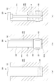
- sectional drawing (a) showing the drilling process in the construction method of the post-construction anchor concerning 1st Embodiment, sectional drawing (b) showing the diameter-expansion process, and sectional drawing (c) showing the injection
- the post-construction anchor is a so-called metal expansion anchor provided to support a structure, equipment, or the like with respect to a concrete frame such as a slab, an outer wall, or an inner wall, or a concrete foundation.
- the post-installed anchor according to the present embodiment can prevent poor driving, and can maintain high pullout strength in cooperation with an anchor hole having an enlarged diameter portion.
- the post-installed anchor system is a system of post-installed anchors and a drill bit for expanding the diameter to form this specially shaped anchor hole. Therefore, before explaining the post-installed anchor in detail, the diameter-expanding drill bit for forming the anchor hole and the diameter-enlarged portion of the anchor hole will be briefly described.
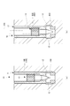
- Fig. 1 shows anchor holes formed in a concrete frame.
- the anchor hole 100 is formed in a straight-shaped prepared hole portion 102 drilled in the housing 101 and at a deeper diameter than the prepared hole portion 102 on the back side (front end side) of the prepared hole portion 102.
- the enlarged diameter portion 103 is provided.
- the enlarged diameter portion 103 is configured by a cylindrical portion that protrudes outward from the pilot hole portion 102 with two annular stepped portions 104.
- the pilot hole part 102 has the long opening side hole part 102a by the side of an opening part on both sides of the enlarged diameter part 103, and the short bottom side hole part 102b by the side of a hole bottom.
- the prepared hole portion 102 and the enlarged diameter portion 103 are formed using different drill bits.
- FIG. 2 shows a diameter expansion device including a diameter expansion drill bit.
- the diameter expansion device 200 includes an electric drill 201 as a power source, a coolant attachment 202 attached to the electric drill 201, and a diameter expansion drill bit 203 attached to the coolant attachment 202.
- a coolant supply device (not shown) is connected to the coolant attachment 202, and the coolant is supplied from the coolant supply device to the diameter-expansion drill bit 203 via the coolant attachment 202.
- the diameter-expanding drill bit 203 includes a bit portion 211 that expands the diameter of the pilot hole portion 102 at the distal end portion, and a shaft portion 212 that is detachably attached to the coolant attachment 202 on the proximal end side.
- the bit part 211 includes two cutting edge parts 221 that grind the pilot hole part 102 to form the enlarged diameter part 103, a cutting edge holding part 222 that holds the two cutting edge parts 221 in a radial direction, And a shank portion 223 that supports the two cutting edge portions 221 via the cutting edge holding portion 222.
- the shank part 223 and the shaft part 212 are integrally formed.
- the cutting edge portion 221 is constituted by a diamond cutting edge or a cemented carbide cutting edge having a circular arc cross section.
- the two cutting edge portions 221 come into contact with the inner surface of the prepared hole portion 102 and are ground, so that the enlarged diameter portion 103 is formed in the prepared hole portion 102.
- the tip end of the cutting edge holding part 222 slightly protrudes from the cutting edge part 221, and this protruding part becomes the bottom hole 102b.
- the depth of cut of the enlarged diameter portion 103 is sufficient if the post-installed anchor 10 described later is locked in the drawing direction, and is preferably about 0.5 to 1.0 mm.
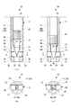
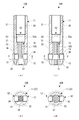
- FIG. 3 is a structural diagram of the post-installed anchor according to the first embodiment
- FIG. 4 is a cross-sectional structural diagram in a state where FIG. 3 is rotated by 90 °.
- this post-installed anchor 10 includes a cylindrical anchor body 11 inserted into the anchor hole 100, and a plurality of (two in the embodiment) provided on the distal end side of the anchor body 11.
- the expansion piece 12 and the cone part 13 which expands the some expansion piece 12 from an inner side are provided.
- the post-installed anchor 10 has a plurality of slidably supporting a plurality of expanded pieces 12 at positions corresponding to the diameter-expanded portions 103 of the anchor body 11 when the anchor body 11 is inserted into the anchor hole 100 (implementation).
- the embodiment is provided with two guide openings 14.
- two guide openings 14 are formed in the lower part of the anchor body 11 corresponding to the enlarged diameter portion 103 so as to be orthogonal to the axial direction of the anchor body 11, and two expanded openings are formed in the two guide openings 14.
- the open piece 12 is slidably supported.
- the anchor main body 11 and the two expanded pieces 12 are formed separately, and these and the cone portion 13 are also formed separately.
- the anchor main body 11, the two expanded pieces 12 and the cone portion 13 are made of soft steel, stainless steel or the like, and constitute a so-called metal expansion anchor.
- the anchor main body 11 has a stepped inner peripheral surface and is formed in a cylindrical shape.
- the anchor main body 11 has a base end side bolt support portion 21 to which a connecting bolt 26 described later is attached, and a front end side fixed to the concrete frame 101. It is integrally formed with the housing fixing part 22 (see FIG. 3).
- the bolt support portion 21 has a female screw portion 25 on its inner peripheral surface, and a male screw portion 42 of a cone portion 13 to be described later is screwed into the female screw portion 25.
- a connecting bolt 26 (generally, a full screw bolt) such as a connecting bolt is screwed in. That is, the cone portion 13 is screwed into the female screw portion 25, and the anchor body 11 is fixed (anchored) to the anchor hole 100, and then the connecting bolt 26 is attached.
- a loose insertion hole 31 is formed on the inner peripheral surface of the housing fixing portion 22 and is connected to the female screw portion 25 and into which a cone portion body 41 of the cone portion 13 described later is loosely inserted.
- the two guide opening portions 14 are formed in the housing fixing portion 22 so as to be orthogonal to the axial direction thereof.
- the two guide openings 14 are arranged at positions corresponding to the enlarged diameter portion 103 when the post-construction anchor 10 (anchor body 11) is inserted into the anchor hole 100.
- the two expanding pieces 12 that are locked to the enlarged diameter portion 103 are held in the two guide openings 14 so as to be slidable in the radial direction.
- Each guide opening 14 is formed so as to penetrate in the radial direction of the housing fixing part 22, and the two guide openings 14 are arranged at 180 ° point symmetrical positions. That is, the two guide openings 14 extend in the diameter direction (direction orthogonal to the axis) of the housing fixing portion 22 with the loose insertion hole 31 interposed therebetween. Accordingly, the two expanding pieces 12 held in the respective guide openings 14 slide and move in opposite directions when expanding.
- Each guide opening 14 is configured by a straight hole having a rectangular cross section.
- the width of the guide opening portion 14 is formed to be the same as the diameter of the loose insertion hole 31 in consideration of the thickness of the housing fixing portion 22 in this portion.
- the height of the guide opening part 14 is formed in the dimension corresponding to the expansion piece 12 which considered the shear resistance.
- two notches 32 are formed at the distal end of the housing fixing portion 22, that is, at the distal end of the anchor main body 11.
- Each notch 32 is formed so as to be cut into a rectangle from the front end of the housing fixing portion 22, and the two notches 32 are located at the same position as the two guide openings 14 in the circumferential direction of the housing fixing portion 22. It is arrange
- the distal end portion of the anchor body 11 has a concavo-convex shape in the circumferential direction, and when a rotational force acts on the anchor body 11, a frictional force against the rotational force is formed between the anchor hole 100 (the bottom thereof). It comes to work. That is, the two notches 32 can prevent the anchor body 11 from being rotated when the cone portion 13 is screwed.
- the post-installed anchor 10 (anchor main body 11) of the present embodiment is a fit that is inserted by lightly striking the anchor hole 100 (the pilot hole 102). For this reason, basically (in terms of design), the anchor main body 11 is not rotated by the screwing of the cone portion 13. However, when the fitting is loose due to an error in manufacturing the post-installed anchor 10 or a drilling error in the anchor hole 100, the accompanying rotation of the anchor main body 11 is prevented by the uneven shape of the tip.
- a fitting portion that fits into the opening of the anchor hole 100 may be provided on the outer peripheral surface of the proximal end portion of the anchor main body 11.
- the shape and number of the notches 32 are arbitrary.
- the shape of the notch 32 is a triangle or an inverted trapezoid.
- the number of the notches 32 is 1 or 3 or more.
- the two spread pieces 12 are slidably held in the guide openings 14 respectively. For this reason, the two expanded pieces 12 are disposed at a 180 ° point-symmetrical position, and at a position corresponding to the enlarged diameter portion 103 when the post-construction anchor 10 (anchor body 11) is inserted into the anchor hole 100. It is arranged.
- Each spreading piece 12 is formed in a rectangular cross section that is complementary to the guide opening 14 having a rectangular cross section. In this case, the expansion piece 12 is a fit that slides smoothly with respect to the guide opening 14 without rattling.
- each spreading piece 12 has a cross-sectional area that can withstand this shearing force.
- the width of the spread piece 12 depends on the width of the guide opening 14, the height of the spread piece 12 ensures a cross-sectional area that can withstand shearing force.
- the length of the axial direction of the diameter expansion part 103 is formed longer than the height of the expansion piece 12 so that the expansion piece 12 at the time of anchoring may be reliably latched by the diameter expansion part 103. .
- each cone portion 13 of each spreading piece 12 has an inclined surface 35 (same angle) following the taper angle of the cone portion 13 (see FIGS. 4A and 4C). ). Since the inner end of the spread piece 12 is formed with a flat slope (see FIG. 4B), the cone portion 13 comes into contact with the spread piece 12 in one line, and this is the diameter. Slide it out of the direction. In addition, you may form the inner end of the expansion piece 12 in planar view "V" shape. In this case, the cone portion 13 comes into linear contact with the spread piece 12 at two locations.
- each expanded piece 12 has an arc surface 36 that follows the outer peripheral surface of the anchor body 11 (the housing fixing portion 22) ( (Refer FIG.4 (b)).
- Each spread piece 12 is temporarily fixed to the anchor body 11 so as not to protrude from the outer peripheral surface of the anchor body 11.
- the expanding piece 12 of the present embodiment is arranged so that the arc surface 36 is flush with the outer peripheral surface of the anchor body 11, and in this state, the expanding piece 12 is weakly bonded (temporarily fixed) to the guide opening 14 with an adhesive. Yes.
- the expanded piece 12 is provided so as to match the depth position of the expanded diameter portion 103 when the post-construction anchor 10 is inserted into the anchor hole 100. Moreover, the expansion piece 12 is formed in the dimension shorter than the diameter expansion part 103 in an axial direction. Although details will be described later, the tip of the post-installed anchor 10 (anchor body 11) is abutted against the bottom of the anchor hole 100 when the cone portion 13 is driven. On the other hand, the position of the enlarged diameter portion 103 from the hole bottom is defined in relation to the aforementioned enlarged diameter device 200 (see FIGS. 5B and 6A).
- the distance to the base end (right end in FIG. 2) is designed to be the same.
- the length of the cutting edge 221 is formed longer than the height of the spread piece 12. That is, the expanded piece 12 of the post-installed anchor 10 anchored in the anchor hole 100 can be easily aligned with the enlarged diameter portion 103 formed by the cutting edge portion 221.
- the cone portion 13 includes a cone portion main body 41 that slides the two expanded pieces 12 outward in the radial direction, and a male screw portion 42 that is screwed into the female screw portion 25 and that pushes the cone portion main body 41 into. ing.
- the cone part main body 41 and the male screw part 42 are integrally formed. When the male screw part 42 is screwed in, the cone part main body 41 advances while rotating and is pushed between the two expanding pieces 12. .
- the male screw portion 42 is formed of a male screw with a hexagonal hole, for example.
- a driver bit 320 is attached to a driver drill and the male screw portion 42 is screwed (see FIG. 6B).
- the torque clutch of the driver drill is set to a predetermined torque value in advance, and the male screw portion 42 is screwed. Thereby, it becomes possible to press-contact the two expansion pieces 12 to the inner peripheral surface of the enlarged diameter portion 103 with a predetermined force without causing individual differences among workers.
- the cone part main body 41 has a body part 45 that is continuous with the male screw part 42 and a tapered part 46 that is continuous with the body part 45.
- the tapered portion 46 is formed in an inverted truncated cone shape whose tip portion is chamfered in a crown sphere shape, that is, in a tapered shape.
- the taper angle of the taper portion 46 is to move each spread piece 12 from the steady position to the pressure contact position, and is formed at a relatively steep angle.
- the male screw portion 42 is screwed by the driver drill, the two spread pieces 12 slide and move outward in the radial direction.
- the tip of each expanded piece 12 abuts against the inner peripheral surface of the enlarged diameter portion 103, it is grasped that the driver drill is idle and the driving of the cone portion 13 is completed by the “click” sound.
- a drilling step (FIG. 5A) for drilling the prepared hole portion 102 using the drilling device 300 and the enlarged diameter portion 103 are formed in the prepared hole portion 102 using the diameter expanding device 200 described above.
- Diameter expansion step (FIG. 5B), injection step (FIG. 5C) for injecting adhesive A into anchor hole 100 using injection device 310, and post-installed anchor 10 is inserted into anchor hole 100
- the injection step can be omitted.
- a drilling device 300 having a diamond core bit 301 attached to an electric drill (not shown) is used to drill the pilot hole 102 having a depth corresponding to the length of the post-installed anchor 10.
- the diamond core bit 301 is used in which the diameter (diameter) of the prepared hole portion 102 is about 0.3 mm thicker than the diameter (outer diameter) of the post-construction anchor 10.
- the cooling liquid can be supplied to the diamond core bit 301 as in the case of the above-described diameter expanding apparatus 200.
- a diamond non-core bit may be used, or drilling may be performed with a vibration drill or a hammer drill (concrete drill bit).
- the above-described diameter expansion apparatus 200 equipped with the diameter expansion drill bit 203 is used.
- the diameter-expanding drill bit 203 is inserted into the prepared hole portion 102 so as to abut against the hole bottom, and the diameter-expanding portion 103 is ground by rotating the diameter-expanding drill bit 203 with the electric drill 201.
- the anchor hole 100 having the enlarged diameter portion 103 at a predetermined depth position of the prepared hole portion 102 is formed.
- the coolant is also supplied to the pair of cutting blade portions 221 in this diameter-expanding drill bit 203.
- supply of a cooling fluid is continued for a short time, and the anchor hole 100 is wash
- an injection device 310 including a pump part (not shown) and a nozzle part 311 is used.
- the nozzle part 311 is inserted into the anchor hole 100 so as to abut against the hole bottom, and the adhesive A is injected from the innermost part of the anchor hole 100 by pumping of the pump part.
- the adhesive A for example, a two-pack type epoxy resin type is used.
- the injection amount of the adhesive A is set such that the adhesive A does not protrude from the anchor hole 100 when the post-construction anchor 10 is inserted into the anchor hole 100 (insertion step), and the adhesive A expands. It is preferable to adhere to the piece 12 or the cone part 13.
- the process proceeds to an insertion step and an anchoring step. The insertion step and the anchoring step are completed before the adhesive A is cured.
- the post-installed anchor 10 is inserted into the anchor hole 100 so as to abut against the hole bottom.
- the post-construction anchor 10 is lightly tapped with a hammer or the like and inserted into the anchor hole 100.
- the post-construction anchor 10 is submerged in the anchor hole 100, and the expanded piece 12 of the post-construction anchor 10 is in a state where it matches the diameter-expanded portion 103 of the anchor hole 100.
- the cone portion 13 is screwed with a constant torque (driving the cone portion 13) using a driver drill or the like equipped with a driver bit 320.
- the two expanded pieces 12 are expanded (moved) radially outward and are pressed against the expanded portion 103 of the anchor hole 100.
- the operator confirms the idling of the driver drill and ends the anchoring process.
- the adhesive A waits for curing (curing).
- the cone 13 is screwed with a relatively small torque. Only the spread pieces 12 can be easily slid in the radial direction. That is, the anchoring work can be performed easily and stably regardless of the skill level of the worker. Moreover, since the two expanded pieces 12 which protruded are latched so that it may catch on the enlarged diameter part 103, high extraction strength can be maintained reliably.
- the cone portion main body 41 is pushed in by a screw-in type using the male screw portion 42, the diameter-enlarged portions 103 of the two expanded pieces 12 can be obtained by fixing the tightening torque of the male screw portion 42 by a driver drill or the like.
- the pressure contact force can also be made constant.
- the male screw portion 42 is screwed into the female screw portion 25, the cone portion main body 41 can be prevented from loosening even if the two expanding pieces 12 receive a strong reaction force from the enlarged diameter portion 103.
- the spread piece 12 and the cone portion 13 are fixed by the adhesive A, also in this respect, the loosening of the cone portion main body 41 can be prevented.
- the number of the spreading pieces 12 and the guide openings 14 may be three or more. However, it is preferable that the three or more spread pieces 12 and the guide openings 14 are equally arranged in the circumferential direction. Further, the cross-sectional shapes of the spreading piece 12 and the guide opening 14 may be a circle, an inverted triangle, an inverted trapezoid, or the like. Further, the enlarged diameter portion 103 may have a tapered outer peripheral surface.
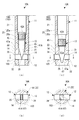
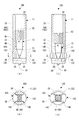
- the female thread portion 25 of the bolt support portion 21 in the anchor body 11 is composed of a first female thread portion 25a for the connecting bolt 26 and a second female thread portion 25b for the cone portion 13.
- the 2nd internal thread part 25b is formed in the small diameter with respect to the 1st internal thread part 25a.
- the cone portion 13 includes a cone portion main body 41A and a male screw portion 42A as in the first embodiment, but the cone portion main body 41A of the second embodiment is formed in a wedge shape. Accordingly, unlike the cone portion 13 of the first embodiment, the cone portion main body 41A and the male screw portion 42A are formed separately. That is, since the male screw portion 42A is screwed into the second female screw portion 25b, the male screw portion 42A moves forward by being screwed in. However, the cone portion main body 41A is pressed by the male screw portion 42A, and thus between the two spread pieces 12. Is pushed into.
- the cone part main body 41 is formed by cutting one half of a cylindrical body into a wedge shape, and is integrally formed by a trunk part 45 at the base end side half and a wedge part 47 at the tip end side half. Also in this case, the inner end surface of each spreading piece 12 is an inclined surface 35 having a shape complementary to the wedge inclined surface 47 a of the wedge portion 47.
- each of the expanded pieces 12 can be smoothly and smoothly slid by the wedge slope 47a of the wedge portion 47. Further, if the tightening torque of the male screw portion 42A is made constant, the pressure contact force to the enlarged diameter portion 103 of the plurality of expanded pieces 12 can also be made constant.
- the cone part main body 41A may be obtained by cutting one half of the prismatic body into a wedge shape.
- a post-construction anchor 10B according to the third embodiment will be described with reference to FIG.
- the cone portion 13 is supported rotatably on the inner peripheral surface of the anchor body 11 and the cone portion main body 51 for sliding the two spread pieces 12 outward in the radial direction.
- a bolt portion 52 that is screwed in the axial direction with respect to the cone portion main body 51.
- the bolt part 52 has a head part 52 a with a hexagonal hole, and the head part 52 a is formed between the female screw part 25 (corresponding to the first female screw part 25 a described above) and the loose insertion hole 31.
- the attached hole 53 is rotatably supported.
- the shaft portion 52 b of the bolt portion 52 in which the male screw is formed extends to a position near the tip of the anchor body 11.
- the shaft portion 52b is screwed into the cone portion main body 51 in which a female screw is formed in the shaft center portion. For this reason, when the bolt part 52 is rotated forward and backward, the cone part main body 51 advances and retreats.
- the cone part main body 51 is formed in a truncated cone shape, and is engaged with the two spread pieces 12 from the distal end side of the anchor main body 11.
- the cone part main body 51 is attracted and the two spread pieces 12 slide and move outward in the radial direction.
- the two expanding pieces 12 are expanded by attracting the cone main body 51 by the bolt 52.
- the tightening torque of the bolt part 52 is made constant by a driver drill or the like, the pressure contact force of the plurality of expanded pieces 12 to the enlarged diameter part 103 can be made constant.
- the cone portion main body 51 is screwed into the bolt portion 52, the cone portion main body 51 can be prevented from loosening even if the expanded piece 12 receives a strong reaction force from the enlarged diameter portion 103.
- the cone body 51 may be wedge-shaped as in the second embodiment. Moreover, in said embodiment, although the cone part main body 51 is attracted
- the post-construction anchor 10C is different from the first embodiment in the shapes of the expanded piece 12C and the guide opening 14C.
- two anti-rotation protrusions 61 are provided at the distal end of the anchor main body 11 for preventing the rotation in place of the two notches 32 described above.
- the male screw portion 42 is provided with a single character hole (minus screwdriver) in place of the tool hexagon hole (hexagon wrench).
- Each of the expanding pieces 12C of this embodiment has a radially leading end side half formed in a fan shape in a plan view.
- the distal end side half of the spread piece 12 ⁇ / b> C is formed such that the opening angle forms an angle of 90 ° from the center of the anchor body 11.
- the guide opening 14 ⁇ / b> C is also formed at an angle of 90 ° from the center of the anchor body 11.
- 90 ° ⁇ 2 180 ° in the circumferential direction of the anchor main body 11 becomes the guide opening 14C, and the cross-sectional area of the portion excluding the guide opening 14C and the cross-sectional relationship of the fan-shaped portions of the two expanded pieces 12C. Is the same.
- This also increases the catching length of the expanded piece 12C with respect to the enlarged diameter portion 103 as much as possible.
- the two rotation stop projections 61 are provided so as to protrude from the tip of the anchor body 11 at a 180 ° point symmetrical position.
- Each rotation stop protrusion 61 is formed by a protrusion having a sharp tip at the front side in the rotation direction of the male screw portion 42 as a vertical side and the rear side as an inclined side.
- the frictional resistance between the rotation stop projection 61 of the anchor main body 11 and the bottom of the anchor hole 100 becomes extremely larger than the frictional resistance when the male threaded portion 42 is rotated. It is possible to prevent the anchor body 11 from being accompanied by the tightening of the cone portion 13).
- each of the expanding pieces 12C can be smoothly expanded without difficulty by the cone portion 13. Further, if the tightening torque of the male screw portion 42 is made constant, the pressure contact force to the enlarged diameter portion 103 of the plurality of expanded pieces 12C can be made constant. Furthermore, the pull-out strength can be increased by the fan-shaped spread piece 12C.
- the cone portion 13 is driven by a screw-in type. That is, the cone part 13 is composed of cone part main bodies 41, 41A, 51 and male screw parts (bolt parts) 42, 42A, 52.
- the male screw portions (bolt portions) 42, 42A, 52 can be omitted, and the cone portion 13 can be configured only by members corresponding to the cone portion main bodies 41, 41A, 51 (not shown).
- the cone portion 13 is driven toward the two spread pieces 12 and 12C using a driving rod inserted into the anchor main body 11 (in the third embodiment, the anchor main body 11 is driven).
- the two spread pieces 12 and 12C can be appropriately spread with a relatively small driving force.
- At least one of the contact portions between the cone body 41, 41A, 51 and the spread pieces 12, 12C may be an inclined surface (tapered surface). Furthermore, the guide openings 14 and 14C may have an upward slope.
- a post-construction anchor 10D according to the fifth embodiment will be described with reference to FIG.
- the cone portion 13D is configured to slide the two spread pieces 12 outward in the radial direction by simply rotating 90 °.
- the expansion piece 12 and the guide opening part 14 have the same basic form as 4th Embodiment.
- the cone portion 13D is integrally formed with a head portion 91 with a hexagonal hole that is rotatably supported on the inner peripheral surface of the anchor body 11, and a cam portion 92 that is continuous with the head portion 91.
- the cam portion 92 is formed in a substantially rhombus shape in cross section, and comes into contact with the two spread pieces 12 on the outer peripheral surface thereof.
- a split slit 93 is formed in the cam portion 92 so as to divide the major axis direction into two. The split slit 93 allows the cam portion 92 to exhibit a spring property in the major axis direction.
- the state in which the two short-diameter tip portions 92a of the cam portion 92 are in contact with the two expanding pieces 12 is the non-expanding state of the two expanding pieces 12, and the cam portion 92 starts to rotate from this state.
- the two spread pieces 12 gradually expand.
- the cam portion 92 rotates 90 °, the two long-diameter tip portions 92b of the cam portion 92 come into contact with both the expanded pieces 12 with spring properties, and the two expanded pieces 12 are in the expanded state.
- a small V-groove 12a is formed on the base end face of each expanding piece 12 to engage with each long-diameter distal end 92b of the cam 92 rotated 90 °.
- the cam portion 92 rotates 90 ° and the two expanded pieces 12 are in the expanded state, the long-diameter leading end portion 92b of the cam portion 92 falls into the V-groove 12a, and the expanded state of the two expanded pieces 12 is confirmed. Is done.
- each of the expanding pieces 12 can be expanded smoothly without difficulty by simply rotating the cone portion 13D by 90 °.
- the cam portion 92 may be formed in an elliptical cross section.
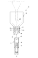
- a rotation stopping jig 80 for preventing the anchor main body 11 from being rotated is prepared.
- the rotation stopping jig 80 includes a steel jig main body 81 and an aluminum jig holder 82 with the jig main body 81 attached to the tip.
- the anchor main body 11 of the post-construction anchor 10 is formed with a pair of engagement recesses 83 at the base end portion (the illustrated one illustrates the post-construction anchor 10 of the first embodiment).
- the jig body 81 is provided with a cylindrical fixing portion 85 in which a tool insertion hole 85a for tightening the cone portion 13 is formed on the inner side thereof, and protrudes from the distal end portion of the fixing portion 85. And a pair of engaging convex portions 86 that engage with each other. Further, a male screw 85 b for screwing the jig main body 81 to the jig holder 82 is formed on the outer peripheral surface of the fixed portion 85.
- the jig holder 82 is entirely formed in a funnel shape, and a female screw 82a into which the jig main body 81 is screwed is formed at the tip.
- the fixing portion 85 of the jig main body 81 is submerged in the front end of the jig holder 82, and only a pair of engaging convex portions 86 are projected.
- the inside of the jig holder 82 and the insertion hole 85a of the jig main body 81 communicate with each other.
- the anti-rotation jig 80 configured as described above handles the jig holder 82 holding the jig main body 81, and the engagement protrusion 86 of the jig main body 81 is inserted into the anchor hole 100. Engage with the engaging recess 83. Thereby, useless rotation of the anchor main body 11 is prevented.
- a tool for example, a driver bit 320 for tightening this to the cone portion 13 is inserted through the insertion hole 85a, and the cone portion 13 is tightened.
Landscapes
- Engineering & Computer Science (AREA)
- General Engineering & Computer Science (AREA)
- Mechanical Engineering (AREA)
- Architecture (AREA)
- Physics & Mathematics (AREA)
- Electromagnetism (AREA)
- Civil Engineering (AREA)
- Structural Engineering (AREA)
- Joining Of Building Structures In Genera (AREA)
- Dowels (AREA)
- Foundations (AREA)
- Earth Drilling (AREA)
Abstract
Description
アンカーは、基部側の大径軸部と、大径軸部に連なるプラグと、プラグに装着されたスリーブとを備えている。プラグは、環状突起部およびこれに連なるテーパー面を有し、スリーブは、この環状突起部およびテーパー面に対応して嵌合溝および拡張部を有している。そして、アンカーを下孔に投入すると、拡張部の下端がテーパー孔部の底に当接する。
この状態で、大径軸部を打ち込むと、プラグのテーパー面がスリーブの拡張部を押し開くと同時に、プラグの環状突起部がスリーブの嵌合溝に嵌合する。押し開かれた拡張部はテーパー孔部に圧接され、これによりスリーブが躯体にアンカリング(定着)される。また、嵌合溝に嵌合した環状突起部は抜止め状態となり、引抜き方向において、スリーブ、プラグおよび大径軸部が一体化する。
また、大径軸部の打ち込みにより、プラグの環状突起部をスリーブの嵌合溝に嵌合させる構造であるため、環状突起部が嵌合溝の縁部を越えるとき(1回目)、および環状突起部が嵌合溝に完全に嵌合したとき(2回目)に、打込み負荷が大きくなる。このため、1回目の打込み負荷を2回目の打込み負荷と勘違いし、打込み作業を終了してしまうおそれがあった。かかる場合には、アンカーは、下孔から簡単に抜け落ちてしまう。
この後施工アンカー10Aでは、アンカー本体11におけるボルト支持部21の雌ねじ部25が、連結ボルト26用の第1雌ねじ部25aと、コーン部13用の第2雌ねじ部25bとで構成されている。そして、第1雌ねじ部25aに対し第2雌ねじ部25bは小径に形成されている。
この後施工アンカー10Bでは、コーン部13が、2つの拡開片12を半径方向の外方にスライドさせるコーン部本体51と、頭部52aをアンカー本体11の内周面に回転自在に支持され、コーン部本体51に対し軸方向に螺合するボルト部52と、を有している。
この後施工アンカー10Cは、拡開片12Cおよびガイド開口部14Cの形状が、第1実施形態と異なるものとなっている。また、アンカー本体11の先端部には、上記の2つの切欠き部32に代えて、連れ回り防止用の2つの回転止め突起61が設けられている。さらに、雄ねじ部42には、工具用の六角穴(六角レンチ)に代えて一文字穴(マイナスドライバー)が設けられている。
この後施工アンカー10Dでは、コーン部13Dが、単純に90°回転することにより、2つの拡開片12を半径方向の外方にスライドさせる構成になっている。また、拡開片12およびガイド開口部14は、第4実施形態と同様の基本形態を有している。
Claims (15)
- 所定の深さ位置に拡径部を有するアンカー穴にアンカリングされる後施工アンカーであって、
前記アンカー穴に挿入されるアンカー本体と、
前記拡径部に向かって拡開するように、前記アンカー本体にスライド自在に設けられた複数の拡開片と、
前記複数の拡開片を外方にそれぞれスライドさせるコーン部と、を備えたことを特徴とする後施工アンカー。 - 前記各拡開片は、前記アンカー本体に対し半径方向にスライド自在に設けられていることを特徴とする請求項1に記載の後施工アンカー。
- 前記複数の拡開片は、180°点対称位置に配設された2つの前記拡開片で構成されていることを特徴とする請求項2に記載の後施工アンカー。
- 前記各拡開片は、前記アンカー本体に形成されたガイド開口部にスライド自在に設けられ、且つ前記ガイド開口部に対し相補的形状に形成されていることを特徴とする請求項2または3に記載の後施工アンカー。
- 前記各拡開片の先端面は、前記アンカー本体の外周面に倣った円弧面に形成されていることを特徴とする請求項1ないし4のいずれか一項に記載の後施工アンカー。
- 前記各拡開片は、係止側先端部が前記アンカー本体の外周面に対し非突出状態となるように、前記アンカー本体に仮固定されていることを特徴とする請求項1ないし5のいずれか一項に記載の後施工アンカー。
- 前記コーン部は、前記複数の拡開片を半径方向の外方に移動させるコーン部本体と、
前記アンカー本体の内周面に形成された雌ねじ部に螺合し、前記コーン部本体を押し込む雄ねじ部と、を有していることを特徴とする請求項1ないし6のいずれか一項に記載の後施工アンカー。 - 前記コーン部本体は、テーパー形状に形成されたテーパー部を含み、
前記コーン部本体と前記雄ねじ部とは、一体に形成されていることを特徴とする請求項7に記載の後施工アンカー。 - 前記コーン部本体は、前記複数の拡開片に対応する複数の傾斜面を有する楔部を含み、
前記コーン部本体と前記雄ねじ部とは、別体に形成されていることを特徴とする請求項7に記載の後施工アンカー。 - 前記コーン部は、前記複数の拡開片を半径方向の外方に移動させるコーン部本体と、
頭部を前記アンカー本体の内周面に回転自在に支持され、前記コーン部本体に対し軸方向に螺合するボルト部と、を有していることを特徴とする請求項1ないし6のいずれか一項に記載の後施工アンカー。 - 前記アンカー本体の先端部には、前記コーン部の締め込みに伴う前記アンカー本体の連れ回りを阻止する回転止め突起が突設されていることを特徴とする請求項8ないし10のいずれか一項に記載の後施工アンカー。
- 請求項1ないし11のいずれか一項に記載の後施工アンカーの施工方法であって、
前記アンカー穴の下穴部を穿孔する穿孔工程と、
前記下穴部に前記拡径部を形成する拡径工程と、
前記後施工アンカーを、前記アンカー穴に挿入する挿入工程と、
前記コーン部により、前記複数の拡開片を拡開させるアンカリング工程と、を備えたことを特徴とする後施工アンカーの施工方法。 - 前記拡径工程と前記挿入工程との間に、前記アンカー穴に接着剤を注入する注入工程を、更に備えたことを特徴とする請求項12に記載の後施工アンカーの施工方法。
- 請求項1ないし11のいずれか一項に記載の後施工アンカーと、
先端部に、前記アンカー穴に前記拡径部を形成する切刃部を有する拡径用ドリルビットと、を備え、
軸方向において、前記各拡開片の長さに対し前記切刃部の長さが長く形成され、且つ前記後施工アンカーの先端から前記各拡開片の基端までの距離と、前記拡径用ドリルビットの先端から前記切刃部の基端までの距離と、が略同一であることを特徴とする後施工アンカーシステム。 - 前記アンカー本体の基端部に係合凹部を形成した請求項7ないし11のいずれか一項に記載の後施工アンカーに対し、前記コーン部の締め込みに伴う前記アンカー本体の連れ回りを阻止する回転止め治具であって、
先端部に前記係合凹部に係合する係合凸部を有すると共に、内側に前記コーン部を締め込むための工具用の挿通孔を形成した円筒状の治具本体と、
先端部で前記治具本体を保持すると共に、ロート状に形成された治具ホルダーと、を備えたことを特徴とする回転止め治具。
Priority Applications (7)
| Application Number | Priority Date | Filing Date | Title |
|---|---|---|---|
| RU2016141060A RU2016141060A (ru) | 2014-05-15 | 2014-08-21 | Устанавливаемый анкер, способ установки устанавливаемого анкера, система устанавливаемого анкера и предотвращающее вращение приспособление |
| EP14892038.2A EP3085973A4 (en) | 2014-05-15 | 2014-08-21 | Post-installed anchor, post-installed anchor implementation method, post-installed anchor system and rotation-stopping tool |
| CN201480074157.7A CN105934591A (zh) | 2014-05-15 | 2014-08-21 | 后施工锚、后施工锚的施工方法、后施工锚系统以及止转夹具 |
| US15/304,334 US20170044756A1 (en) | 2014-05-15 | 2014-08-21 | Post-installed anchor, method for installing post-installed anchor, post-installed anchor system, and rotation preventing jig |
| SG11201608641WA SG11201608641WA (en) | 2014-05-15 | 2014-08-21 | Post-installed anchor, post-installed anchor implementation method, post-installed anchor system and rotation-stopping tool |
| KR1020167017311A KR101946896B1 (ko) | 2014-05-15 | 2014-08-21 | 후시공 앵커, 후시공 앵커의 시공 방법, 후시공 앵커 시스템 및 회전 방지 지그 |
| JP2016518655A JP6404335B2 (ja) | 2014-05-15 | 2014-08-21 | 後施工アンカーおよび後施工アンカーの施工方法 |
Applications Claiming Priority (2)
| Application Number | Priority Date | Filing Date | Title |
|---|---|---|---|
| JP2014-101198 | 2014-05-15 | ||
| JP2014101198 | 2014-05-15 |
Publications (1)
| Publication Number | Publication Date |
|---|---|
| WO2015173849A1 true WO2015173849A1 (ja) | 2015-11-19 |
Family
ID=54479425
Family Applications (1)
| Application Number | Title | Priority Date | Filing Date |
|---|---|---|---|
| PCT/JP2014/004315 Ceased WO2015173849A1 (ja) | 2014-05-15 | 2014-08-21 | 後施工アンカー、後施工アンカーの施工方法、後施工アンカーシステムおよび回転止め治具 |
Country Status (8)
| Country | Link |
|---|---|
| US (1) | US20170044756A1 (ja) |
| EP (1) | EP3085973A4 (ja) |
| JP (1) | JP6404335B2 (ja) |
| KR (1) | KR101946896B1 (ja) |
| CN (1) | CN105934591A (ja) |
| RU (1) | RU2016141060A (ja) |
| SG (1) | SG11201608641WA (ja) |
| WO (1) | WO2015173849A1 (ja) |
Cited By (4)
| Publication number | Priority date | Publication date | Assignee | Title |
|---|---|---|---|---|
| JP2017113889A (ja) * | 2015-12-21 | 2017-06-29 | Fsテクニカル株式会社 | 整形用ドリルビットおよび複合ドリルビット |
| CN112049848A (zh) * | 2020-10-01 | 2020-12-08 | 庞长青 | 一种可重复利用的膨胀螺栓 |
| JP2023074018A (ja) * | 2019-05-30 | 2023-05-26 | Fsテクニカル株式会社 | 螺合治具 |
| KR102931730B1 (ko) * | 2023-12-20 | 2026-02-25 | 한국수력원자력 주식회사 | 후설치 앵커 |
Families Citing this family (11)
| Publication number | Priority date | Publication date | Assignee | Title |
|---|---|---|---|---|
| KR20160095012A (ko) * | 2014-11-20 | 2016-08-10 | 에프에스 테크니칼 코포레이션 | 앵커 구멍의 형성 방법 및 확경 장치 |
| CN106286522A (zh) * | 2016-11-03 | 2017-01-04 | 徐州工程学院 | 一种自粘式锚固钉 |
| CN109723707A (zh) * | 2017-10-27 | 2019-05-07 | 河南奔马股份有限公司 | 孔用连接装置 |
| CN109356922A (zh) * | 2018-12-10 | 2019-02-19 | 重庆大学 | 一种单面螺栓 |
| CN110513373B (zh) * | 2019-07-02 | 2024-03-15 | 青岛海尔洗衣机有限公司 | 一种洗涤设备安装组件、安装方法及壁挂式洗涤设备 |
| KR102089552B1 (ko) * | 2019-09-10 | 2020-05-26 | 주식회사 에스에스팀버 | 볼트 조립체 |
| CN115315344B (zh) * | 2020-03-31 | 2025-11-25 | 株式会社宫永 | 穿孔装置 |
| WO2021230405A1 (ko) * | 2020-05-15 | 2021-11-18 | 조남현 | 스트롱 앵커 |
| KR102325946B1 (ko) * | 2020-11-30 | 2021-11-15 | 주식회사 태원건설 | 확장형 네일링 및 앵커 시공방법 |
| CN113001307B (zh) * | 2021-03-02 | 2022-03-25 | 上汽大众汽车有限公司 | 一种曲轴孔去毛刺装置 |
| KR102700655B1 (ko) * | 2023-12-29 | 2024-08-28 | 박태영 | 사방확산 지압형 앵커조립체 |
Citations (6)
| Publication number | Priority date | Publication date | Assignee | Title |
|---|---|---|---|---|
| JPS5149358A (en) * | 1974-10-25 | 1976-04-28 | Hitachi Ltd | Ankaa boruto |
| JPS5551113A (en) * | 1978-10-06 | 1980-04-14 | Sanchez Velasco Vicente | Fixing device for element being to support on completed structure |
| JPS5771947A (en) * | 1980-10-20 | 1982-05-06 | Hitoshi Sakurai | Hole-in anchor |
| JPS629717U (ja) * | 1985-07-03 | 1987-01-21 | ||
| JPS63186017A (ja) * | 1987-01-28 | 1988-08-01 | 弥生スチール株式会社 | アンカ− |
| JPH02114207U (ja) * | 1989-03-01 | 1990-09-12 |
Family Cites Families (13)
| Publication number | Priority date | Publication date | Assignee | Title |
|---|---|---|---|---|
| DE3128610A1 (de) * | 1981-07-20 | 1983-01-27 | Hilti AG, 9494 Schaan | Spreizduebel |
| DE3325800A1 (de) * | 1983-07-16 | 1985-01-31 | Heinrich 6102 Pfungstadt Liebig | Klebeanker |
| CN85105233A (zh) * | 1985-04-17 | 1986-10-22 | 莫诺格拉姆工业有限公司 | 一种改进了的用于自动插入和抽出工具的强制松脱钢丝轴销型夹具 |
| JP2003159704A (ja) * | 2001-11-28 | 2003-06-03 | Hitachi Building Systems Co Ltd | アンカーボルト用穿孔の製作方法と穿孔装置 |
| US7150596B2 (en) * | 2002-02-07 | 2006-12-19 | Carroll Diaz | Toggle bolt device |
| US20050183380A1 (en) | 2002-02-21 | 2005-08-25 | Yoshinori Sato | Post-construction anchor, and drill bit for drilling prepared holes therefor |
| JP3779981B2 (ja) * | 2004-02-27 | 2006-05-31 | 寛治 ▲魚▼谷 | アンカーとその仮固定方法及びそれを用いた仮固定構造並びにアンカー取付用治具 |
| EP1602428A1 (de) * | 2004-06-03 | 2005-12-07 | A & M Electric Tools GmbH | Handgeführtes Elektrowerkzeug |
| JP5067892B2 (ja) * | 2006-10-31 | 2012-11-07 | 株式会社ライセンス&プロパティコントロール | アンカーとその固定方法及びそれを用いた固定構造 |
| WO2010130185A1 (zh) * | 2009-05-14 | 2010-11-18 | 福建鹏坤实业有限公司 | 一种锚栓 |
| WO2012070272A1 (ja) * | 2010-11-25 | 2012-05-31 | 株式会社ハマ・システム | ボルト |
| AU2012367292B2 (en) * | 2012-01-26 | 2016-09-22 | Empire Technology Development Llc | Expanding fastener |
| US9028184B2 (en) * | 2012-10-19 | 2015-05-12 | Dennis Bone | Protrusion anchor assembly |
-
2014
- 2014-08-21 RU RU2016141060A patent/RU2016141060A/ru unknown
- 2014-08-21 CN CN201480074157.7A patent/CN105934591A/zh active Pending
- 2014-08-21 US US15/304,334 patent/US20170044756A1/en not_active Abandoned
- 2014-08-21 WO PCT/JP2014/004315 patent/WO2015173849A1/ja not_active Ceased
- 2014-08-21 KR KR1020167017311A patent/KR101946896B1/ko active Active
- 2014-08-21 SG SG11201608641WA patent/SG11201608641WA/en unknown
- 2014-08-21 EP EP14892038.2A patent/EP3085973A4/en not_active Withdrawn
- 2014-08-21 JP JP2016518655A patent/JP6404335B2/ja active Active
Patent Citations (6)
| Publication number | Priority date | Publication date | Assignee | Title |
|---|---|---|---|---|
| JPS5149358A (en) * | 1974-10-25 | 1976-04-28 | Hitachi Ltd | Ankaa boruto |
| JPS5551113A (en) * | 1978-10-06 | 1980-04-14 | Sanchez Velasco Vicente | Fixing device for element being to support on completed structure |
| JPS5771947A (en) * | 1980-10-20 | 1982-05-06 | Hitoshi Sakurai | Hole-in anchor |
| JPS629717U (ja) * | 1985-07-03 | 1987-01-21 | ||
| JPS63186017A (ja) * | 1987-01-28 | 1988-08-01 | 弥生スチール株式会社 | アンカ− |
| JPH02114207U (ja) * | 1989-03-01 | 1990-09-12 |
Non-Patent Citations (1)
| Title |
|---|
| See also references of EP3085973A4 * |
Cited By (5)
| Publication number | Priority date | Publication date | Assignee | Title |
|---|---|---|---|---|
| JP2017113889A (ja) * | 2015-12-21 | 2017-06-29 | Fsテクニカル株式会社 | 整形用ドリルビットおよび複合ドリルビット |
| JP2023074018A (ja) * | 2019-05-30 | 2023-05-26 | Fsテクニカル株式会社 | 螺合治具 |
| JP7427297B2 (ja) | 2019-05-30 | 2024-02-05 | Fsテクニカル株式会社 | 螺合治具 |
| CN112049848A (zh) * | 2020-10-01 | 2020-12-08 | 庞长青 | 一种可重复利用的膨胀螺栓 |
| KR102931730B1 (ko) * | 2023-12-20 | 2026-02-25 | 한국수력원자력 주식회사 | 후설치 앵커 |
Also Published As
| Publication number | Publication date |
|---|---|
| KR20160095013A (ko) | 2016-08-10 |
| CN105934591A (zh) | 2016-09-07 |
| RU2016141060A3 (ja) | 2018-06-15 |
| EP3085973A1 (en) | 2016-10-26 |
| SG11201608641WA (en) | 2016-12-29 |
| KR101946896B1 (ko) | 2019-02-12 |
| RU2016141060A (ru) | 2018-06-15 |
| US20170044756A1 (en) | 2017-02-16 |
| JPWO2015173849A1 (ja) | 2017-04-20 |
| EP3085973A4 (en) | 2017-07-26 |
| JP6404335B2 (ja) | 2018-10-10 |
Similar Documents
| Publication | Publication Date | Title |
|---|---|---|
| JP6404335B2 (ja) | 後施工アンカーおよび後施工アンカーの施工方法 | |
| US10837480B2 (en) | Hollow wall anchor | |
| US20090103999A1 (en) | Toggle bolt assembly | |
| US9028184B2 (en) | Protrusion anchor assembly | |
| JP5946202B1 (ja) | あと施工アンカー | |
| US20150316088A1 (en) | Screwcon | |
| NO179685B (no) | Selvborende anker | |
| JPWO2015118702A1 (ja) | 緩み止め機能を備えたボルト | |
| CA2630089A1 (en) | Self-drilling wall anchor device | |
| JP5771337B1 (ja) | 後施工アンカー、後施工アンカーの施工方法および後施工アンカーシステム | |
| WO2016080107A1 (ja) | アンカー穴の形成方法および拡径装置 | |
| JPH109233A (ja) | セルフドリリングアンカー | |
| JP5334427B2 (ja) | 壁材への固定構造、およびアンカーボルト | |
| JP2014218876A (ja) | 後施工アンカー、後施工アンカーの施工方法および後施工アンカーシステム | |
| US1769591A (en) | Tool | |
| TW201712193A (zh) | 附防逆轉機構的錨栓 | |
| JPS63254211A (ja) | アンカー止め部材 | |
| JP7236732B2 (ja) | あと施工アンカーおよびあと施工アンカーの施工方法 | |
| JP2016113762A (ja) | 後施工アンカー、後施工アンカーの施工方法および後施工アンカーシステム | |
| JP6664934B2 (ja) | アンカー | |
| JP6378764B2 (ja) | アンカ装置の設置方法およびかかる方法を実行するための装置 | |
| WO2016092675A1 (ja) | 後施工アンカー、後施工アンカーの施工方法および後施工アンカーシステム | |
| JP2016223116A (ja) | 後施工アンカーおよび後施工アンカーの施工方法 | |
| JP2016199967A (ja) | 後施工アンカー、後施工アンカーの施工方法および後施工アンカーシステム | |
| JP7339789B2 (ja) | アンカー及びアンカー施工方法 |
Legal Events
| Date | Code | Title | Description |
|---|---|---|---|
| 121 | Ep: the epo has been informed by wipo that ep was designated in this application |
Ref document number: 14892038 Country of ref document: EP Kind code of ref document: A1 |
|
| ENP | Entry into the national phase |
Ref document number: 2016518655 Country of ref document: JP Kind code of ref document: A |
|
| ENP | Entry into the national phase |
Ref document number: 20167017311 Country of ref document: KR Kind code of ref document: A |
|
| REEP | Request for entry into the european phase |
Ref document number: 2014892038 Country of ref document: EP |
|
| WWE | Wipo information: entry into national phase |
Ref document number: 2014892038 Country of ref document: EP |
|
| WWE | Wipo information: entry into national phase |
Ref document number: 15304334 Country of ref document: US |
|
| NENP | Non-entry into the national phase |
Ref country code: DE |
|
| ENP | Entry into the national phase |
Ref document number: 2016141060 Country of ref document: RU Kind code of ref document: A |