WO2015173861A1 - キャリブレーション装置 - Google Patents
キャリブレーション装置 Download PDFInfo
- Publication number
- WO2015173861A1 WO2015173861A1 PCT/JP2014/062600 JP2014062600W WO2015173861A1 WO 2015173861 A1 WO2015173861 A1 WO 2015173861A1 JP 2014062600 W JP2014062600 W JP 2014062600W WO 2015173861 A1 WO2015173861 A1 WO 2015173861A1
- Authority
- WO
- WIPO (PCT)
- Prior art keywords
- signal
- frequency domain
- frequency
- arrival
- signals
- Prior art date
- Legal status (The legal status is an assumption and is not a legal conclusion. Google has not performed a legal analysis and makes no representation as to the accuracy of the status listed.)
- Ceased
Links
Images

Classifications
-
- H—ELECTRICITY
- H04—ELECTRIC COMMUNICATION TECHNIQUE
- H04B—TRANSMISSION
- H04B17/00—Monitoring; Testing
- H04B17/20—Monitoring; Testing of receivers
- H04B17/21—Monitoring; Testing of receivers for calibration; for correcting measurements
- H04B17/22—Monitoring; Testing of receivers for calibration; for correcting measurements for calibration of the receiver components
- H04B17/221—Monitoring; Testing of receivers for calibration; for correcting measurements for calibration of the receiver components of receiver antennas, e.g. as to amplitude or phase
-
- H—ELECTRICITY
- H04—ELECTRIC COMMUNICATION TECHNIQUE
- H04B—TRANSMISSION
- H04B1/00—Details of transmission systems, not covered by a single one of groups H04B3/00 - H04B13/00; Details of transmission systems not characterised by the medium used for transmission
- H04B1/06—Receivers
-
- H—ELECTRICITY
- H04—ELECTRIC COMMUNICATION TECHNIQUE
- H04B—TRANSMISSION
- H04B7/00—Radio transmission systems, i.e. using radiation field
- H04B7/02—Diversity systems; Multi-antenna system, i.e. transmission or reception using multiple antennas
-
- H—ELECTRICITY
- H04—ELECTRIC COMMUNICATION TECHNIQUE
- H04B—TRANSMISSION
- H04B7/00—Radio transmission systems, i.e. using radiation field
- H04B7/02—Diversity systems; Multi-antenna system, i.e. transmission or reception using multiple antennas
- H04B7/04—Diversity systems; Multi-antenna system, i.e. transmission or reception using multiple antennas using two or more spaced independent antennas
Definitions
- the present invention relates to a calibration apparatus that compensates for amplitude / phase errors of a plurality of antennas constituting an array antenna that receives radio waves, light waves, sound waves, and the like.
- a calibration device has been developed to compensate for the amplitude error and phase error.
- a calibration signal is injected from between each antenna and the receiving unit, and a calibration signal output from each receiving unit is extracted.
- a calibration method is used to estimate the amplitude error and phase error of each antenna by comparing these calibration signals.
- this calibration method cannot eliminate the error of the antenna body.
- a mechanism for periodically injecting and comparing calibration signals is required.
- Non-Patent Document 2 discloses a technique for performing calibration using a radiation source whose direction of arrival is unknown as a method for solving the above-described problem.
- the received signal is multiplied by the array error matrix expressed by the dimension of the number of array elements x the number of array elements. And calibrate by estimating the array error matrix.
- the array error matrix is a diagonal matrix.
- Non-Patent Document 1 states that the above assumption does not hold in a complex reflection environment around the sensor. It has been.
- the conventional calibration apparatus is configured as described above, if a plurality of radiation sources with known arrival directions are not prepared, the amplitude error and phase error of the plurality of antennas constituting the array antenna are estimated. There was a problem that could not be done.
- the above error estimation process is periodically performed separately from the process of estimating the arrival direction of the signal radiated from the unknown radiation source. There was an issue that had to be repeated.
- the present invention has been made in order to solve the above-described problems.
- a plurality of antennas are used.
- An object of the present invention is to obtain a calibration device capable of estimating an amplitude error and a phase error.
- a calibration apparatus includes an array antenna that receives a signal whose direction of arrival is unknown, a signal conversion unit that converts reception signals of a plurality of element antennas constituting the array antenna into a frequency domain signal, and a signal Of the plurality of frequency domain signals converted by the conversion means, a frequency domain signal related to any one of the element antennas or a frequency spectrum of an unknown signal acquired in advance is set as a reference signal, and the reference signal Using a reference signal normalizing unit that normalizes signals in a plurality of frequency domains, and a signal having a reference frequency included in the signals in the plurality of frequency domains normalized by the reference signal normalizing unit A reference frequency normalizing means for normalizing signals in a plurality of frequency regions normalized by the reference signal normalizing means, and a reference frequency normalizing means.
- An arrival direction estimation means for estimating the arrival direction of an unknown signal using a plurality of normalized frequency domain signals is provided, and the amplitude phase error estimation means refers to the arrival direction estimated by the arrival direction estimation means.
- the amplitude error and phase error of a plurality of antennas are estimated using signals in a plurality of frequency domains normalized by the signal normalization means.
- the frequency domain signal related to any one of the element antennas or the frequency spectrum of an unknown signal acquired in advance is used as the reference signal.
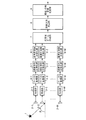
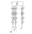
- FIG. 1 is a block diagram showing a calibration apparatus according to Embodiment 1 of the present invention.
- a radiation source 1 is a signal source that emits a signal whose direction of arrival ⁇ is unknown, or a reflector that reflects a signal emitted from another radiation source.
- the receiving antennas 2-1 to 2-M are element antennas constituting an array antenna, and receive a signal whose arrival direction ⁇ is unknown.
- the receiving units 3-1 to 3-M perform various signal processing (for example, signal amplification processing, band-pass filter processing, frequency conversion processing) on the RF signals that are reception signals of the receiving antennas 2-1 to 2-M.
- a baseband complex signal that is a digital signal and output the baseband complex signal to the Fourier transform units 4-1 to 4-M.
- the digital signal obtained by the receiving units 3-1 to 3-M is an IF actual signal
- a baseband complex signal is obtained by performing Hilbert transform or digital quadrature detection on the IF actual signal. May be.
- the Fourier transform units 4-1 to 4 -M perform FFT (Fast Fourier Transform) on the baseband complex signal output from the reception units 3-1 to 3 -M so that the baseband complex signal is frequency-converted.
- a process of converting into a domain signal (hereinafter referred to as a “frequency domain signal”) is performed.
- the signal conversion means is constituted by the receiving units 3-1 to 3-M and the Fourier transform units 4-1 to 4-M.
- the baseband complex signal is subjected to FFT, but the processing is not limited to FFT as long as the process converts the baseband complex signal into a frequency domain signal.
- the baseband complex signal is converted to DFT (Discrete Fourier Transform: (Discrete Fourier transform).
- the reference signal normalization units 5-1 to 5-M set the frequency domain signal related to any one of the reception antennas 2 among the frequency domain signals converted by the Fourier transform units 4-1 to 4-M as reference signals. Then, a process for normalizing the frequency domain signal is performed by dividing the frequency domain signal converted by the Fourier transform units 4-1 to 4-M by the reference signal. Note that the reference signal normalizing units 5-1 to 5-M constitute reference signal normalizing means.
- the frequency domain signal related to any one of the reception antennas 2 is set as the reference signal. However, when the frequency spectrum of the signal radiated from the radiation source 1 is acquired in advance, the frequency spectrum is obtained. May be set as a reference signal.
- the reference frequency normalization units 6-1 to 6-M use the reference frequency signals included in the frequency domain signals normalized by the reference signal normalization units 5-1 to 5-M to use the reference signals. Processing for normalizing the frequency domain signals normalized by the normalizing units 5-1 to 5-M is performed.
- the reference frequency normalization units 6-1 to 6-M constitute reference frequency normalization means.
- the broadband beam forming unit 7 performs processing for forming a broadband beam pattern using the frequency domain signals normalized by the reference frequency normalizing units 6-1 to 6-M.
- the arrival direction estimation unit 8 performs processing for estimating the arrival direction ⁇ of the signal radiated from the radiation source 1 by detecting the peak of the beam pattern formed by the broadband beam forming unit 7.
- the wideband beam forming unit 7 and the arrival direction estimation unit 8 constitute arrival direction estimation means.
- the amplitude / phase error estimator 9 uses the arrival direction ⁇ estimated by the arrival direction estimator 8 and the frequency domain signal normalized by the reference signal normalizers 5-1 to 5 -M to use the receiving antenna 2-1. A process for estimating an amplitude error and a phase error of ⁇ 2-M is performed.
- the amplitude / phase error estimator 9 constitutes an amplitude / phase error estimator.
- the receiving antennas 2-1 to 2-M, the receiving units 3-1 to 3-M, the Fourier transform units 4-1 to 4-M, and the reference signal normalizing unit which are components of the calibration apparatus
- Each of the 5-1 to 5-M, the reference frequency normalization units 6-1 to 6-M, the wideband beam forming unit 7, the arrival direction estimation unit 8, and the amplitude / phase error estimation unit 9 is configured by dedicated hardware.
- the components other than the receiving antennas 2-1 to 2-M and the receiving units 3-1 to 3-M are a semiconductor integrated circuit on which a CPU is mounted, or one A part of the calibration apparatus may be configured with a computer).
- Fourier transform units 4-1 to 4-M when components other than the receiving antennas 2-1 to 2-M and the receiving units 3-1 to 3-M are configured by a computer, Fourier transform units 4-1 to 4-M, a reference signal normalizing unit 5- 1 to 5-M, reference frequency normalization units 6-1 to 6-M, wideband beam forming unit 7, arrival direction estimation unit 8 and amplitude / phase error estimation unit 9 are stored in a computer program. What is necessary is just to make it memorize
- the receiving antennas 2-1 to 2-M constituting the array antenna receive a signal whose direction of arrival ⁇ is radiated from the radiation source 1 and is unknown.
- the receiving units 3-1 to 3-M perform various types of signal processing (for example, signal amplification processing, band-pass filter processing, frequency conversion) on the RF signals that are reception signals of the receiving antennas 2-1 to 2-M.
- the baseband complex signal that is a digital signal is obtained by performing the processing, A / D conversion processing, and the like, and the baseband complex signal is output to the Fourier transform units 4-1 to 4-M.
- the Fourier transform units 4-1 to 4-M When receiving the baseband complex signal from the receiving units 3-1 to 3-M, the Fourier transform units 4-1 to 4-M perform FFT on the baseband complex signal to convert the baseband complex signal in the frequency domain. The signal is converted into a signal, and the frequency domain signal is output to the reference signal normalization units 5-1 to 5-M.
- the reference signal normalization units 5-1 to 5 -M receive the frequency domain signal from the Fourier transform units 4-1 to 4 -M
- the reference signal normalization units 5-1 to 5 -M remove the influence of the frequency spectrum of the radiation source 1.
- the frequency domain signal related to any one of the receiving antennas 2 is set as a reference signal, and the Fourier transform units 4-1 to 4- By dividing the frequency domain signal transformed by M, the frequency domain signal is normalized.
- the frequency domain signal related to any one of the reception antennas 2 is set as the reference signal.
- the frequency spectrum of the signal radiated from the radiation source 1 is acquired in advance, the frequency spectrum is obtained. May be set as a reference signal, and the frequency domain signal may be normalized by dividing the frequency domain signal converted by the Fourier transform units 4-1 to 4-M by the reference signal.
- the frequency domain signal x [m, k] normalized by the reference signal normalization units 5-1 to 5-M is expressed by the following equation (1).
- ⁇ m (f) is a complex amplitude of the m-th receiving antenna 2-m at the frequency f, and means an amplitude error and a phase error of the receiving antenna 2-m.
- f c is the center frequency of the signal radiated from the radiation source 1
- d is the element spacing of the receiving antennas 2-1 ⁇ 2-M
- c is the speed of light
- theta is the direction of arrival of the signal radiated from the radiation source 1
- n [ m, k] is a receiver noise included in the received signal of the m-th receiving antenna 2-m at the frequency index k.
- the element intervals d of the receiving antennas 2-1 to 2-M are equal and the receiving antennas 2-1 to 2-M are arranged on a straight line.
- the element intervals of the receiving antennas 2-1 to 2-M may be unequal, or the receiving antennas 2-1 to 2-M may be two-dimensionally arranged. .
- the reference frequency normalization units 6-1 to 6-M receive the normalized frequency domain signal x [m, k] from the reference signal normalization units 5-1 to 5-M, the reception antennas 2-1 to 2-1
- the frequency domain signal x [m, k] is a reference frequency signal included in the frequency domain signal x [m, k].
- the frequency domain signal is normalized by dividing.
- the complex amplitude ⁇ m (f) is constant in the band of the frequency domain signal x [m, k]
- equation (1) can be expressed as the following equation (2). Is done.
- x tilde [m, k] represents a frequency domain signal after normalization by the reference frequency normalization units 6-1 to 6-M.
- the symbol “ ⁇ ” cannot be added on the letter because of the electronic application, and therefore, it is expressed as x tilde.
- Equation (3) the first term on the right side of Equation (3) is referred to as a “normalized steering vector”.
- the influence of the complex amplitude and the phase error of the receiving antennas 2-1 to 2-M is removed, and the unknown parameter is only the arrival direction ⁇ of the signal radiated from the radiation source 1. .
- the broadband beam forming unit 7 forms a broadband beam pattern using the frequency domain signal x tilde [m, k] normalized by the reference frequency normalizing units 6-1 to 6-M. That is, as shown in the following equation (4), the broadband beam forming unit 7 uses the normalized steering vector (the first term on the right side of the equation (3)) and changes the arrival direction ⁇ to change the broadband beam. Form a pattern.
- P ( ⁇ tilde) means a wide-band beam pattern
- vec ( ⁇ ) means an operation of rearranging the matrix in ( ⁇ ) in the column direction and vectorizing it.
- a tilde m, k ( ⁇ ) means a normalized steering vector
- H means a complex conjugate transpose.
- the arrival direction estimation unit 8 detects the peak (maximum value) of the beam pattern P ( ⁇ tilde) when the broadband beam forming unit 7 forms the broadband beam pattern P ( ⁇ tilde).
- the arrival direction estimation unit 8 detects the peak of the beam pattern P ( ⁇ tilde)
- it specifies the direction corresponding to the peak, and the direction corresponding to the peak is set as the arrival direction ⁇ of the signal radiated from the radiation source 1.
- the amplitude / phase error estimation unit 9 normalizes the arrival direction ⁇ by the reference signal normalization units 5-1 to 5 -M.
- the amplitude error and phase error which are the complex amplitudes ⁇ m (f) of the receiving antennas 2-1 to 2-M, are estimated.
- a least square method is applied to estimate the complex amplitude ⁇ m (f). It is possible to estimate the amplitude error from the absolute value of the complex amplitude gamma m (f), also can be estimated phase error from the complex amplitude gamma phase of m (f).
- the frequency domain signal related to any one of the receiving antennas 2 is referred to among the frequency domain signals transformed by the Fourier transform units 4-1 to 4-M.
- the reference frequency normalization units 6-1 to 6-M for normalizing [m, k] are provided, an unknown signal can be generated without preparing a radiation source with a known direction of arrival in advance. While estimating the direction of arrival ⁇ with high accuracy, An effect that can estimate the amplitude and phase errors of Shin antennas 2-1 ⁇ 2-M.
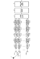
- Embodiment 2 the case where the amplitude error and phase error of the reception antennas 2-1 to 2-M are constant within the band of the reception signal of the reception antennas 2-1 to 2-M has been described. In some cases, the amplitude error and phase error of the receiving antennas 2-1 to 2-M are not constant within the band of the received signal. In the second embodiment, even when the amplitude error and phase error of the reception antennas 2-1 to 2-M are not constant within the band of the reception signal of the reception antennas 2-1 to 2-M, the reception antenna 2-1 A calibration apparatus capable of estimating the amplitude error and phase error of ⁇ 2-M with high accuracy will be described.
- the band dividing units 11-1 to 11-M are composed of, for example, a semiconductor integrated circuit mounting a CPU or a one-chip microcomputer, and are normalized by the reference signal normalizing units 5-1 to 5-M.
- the frequency domain signal x [m, k] is divided into a plurality of bands.
- the band dividing units 11-1 to 11-M constitute band dividing means.
- the reference frequency normalization units 12-1 to 12-M are composed of, for example, a semiconductor integrated circuit mounting a CPU or a one-chip microcomputer, and are divided by the band dividing units 11-1 to 11-M. For each band, processing for normalizing the frequency domain signal in the band is performed using a signal having a reference frequency included in the frequency domain signal in the band.
- the reference frequency normalization units 12-1 to 12-M constitute reference frequency normalization means.
- Band division units 11-1 to 11-M are frequencies obtained by converting reference signal normalization units 5-1 to 5-M by Fourier transform units 4-1 to 4-M, as in the first embodiment.
- the frequency domain signal x [m, k] is divided into a plurality of bands.
- the width of the band for dividing the frequency domain signal x [m, k] differs depending on the actual system, and the amplitude error and phase error of the reception antennas 2-1 to 2-M and the reception units 3-1 to 3-M Determined by frequency characteristics.
- a method of actually injecting an analog signal and measuring it can be considered.
- the reference frequency normalization units 12-1 to 12-M determine a reference frequency (for example, the center frequency of the divided bands) for each band divided by the band dividing units 11-1 to 11-M. .
- the reference frequency normalization units 12-1 to 12-M use signals of the determined reference frequency for each band divided by the band division units 11-1 to 11-M.
- the frequency domain signal in the division band is normalized by dividing the frequency domain signal in the division band.
- the broadband beam forming unit 7 forms a broadband beam pattern using the frequency domain signals of each divided band normalized by the reference frequency normalizing units 6-1 to 6-M. Since the subsequent processing contents are the same as those in the first embodiment, detailed description thereof is omitted.
- the frequency domain signal x [m, k] normalized by the reference signal normalizing units 5-1 to 5-M is divided into a plurality of bands.
- Dividing units 11-1 to 11-M are provided, and the reference frequency normalizing units 12-1 to 12-M perform frequency regions within the band for each band divided by the band dividing units 11-1 to 11-M. Since the frequency domain signal in the band is normalized by using the reference frequency signal included in the signal, the received signal band of the receiving antennas 2-1 to 2-M Even if the amplitude error and the phase error of the receiving antennas 2-1 to 2-M are not constant, the amplitude error and the phase error of the receiving antennas 2-1 to 2-M can be estimated with high accuracy.
- the receiving units 3-1 to 3-M obtain the baseband complex signal from the received signals of the receiving antennas 2-1 to 2-M, and the Fourier transform units 4-1 to 4-M Converts the baseband complex signal into a frequency domain signal by performing FFT on the baseband complex signal. If the SNR (signal-to-noise power ratio) of the received signal is low, the frequency domain signal is It cannot be obtained with high accuracy. Further, when the reference signal normalization units 5-1 to 5 -M normalize the frequency domain signal, if the frequency spectrum of the signal radiated from the radiation source 1 includes a component close to 0, the noise component May be amplified. Therefore, in the second embodiment, a calibration apparatus capable of obtaining the frequency domain signal with high accuracy by increasing the SNR of the reception signals of the reception antennas 2-1 to 2-M will be described.
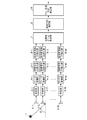
- the cross-correlation calculation units 13-1 to 13-M are composed of, for example, a semiconductor integrated circuit mounting a CPU or a one-chip microcomputer, and the baseband output from the reception units 3-1 to 3-M Of the complex signals, the baseband complex signal related to any one of the receiving antennas 2 is set as a reference signal, and the cross-correlation between the baseband complex signal output from the receiving units 3-1 to 3-M and the reference signal And the SNR improvement process for increasing the SNR of the baseband complex signal output from the receivers 3-1 to 3-M is performed using the cross-correlation result, and the baseband complex signal after the SNR improvement process is calculated.
- the cross-correlation calculating units 13-1 to 13-M constitute a cross-correlation calculating unit.
- the baseband complex signal related to any one of the receiving antennas 2 is set as the reference signal, but when the baseband complex signal of the signal radiated from the radiation source 1 is acquired in advance, The baseband complex signal may be set as a reference signal.
- the cross-correlation calculating units 13-1 to 13-M are associated with any one of the receiving antennas 2 when the receiving units 3-1 to 3-M output baseband complex signals.
- the baseband complex signal is set as a reference signal, and the cross-correlation between the baseband complex signal output from the receiving units 3-1 to 3-M and the reference signal is calculated.
- This cross-correlation may be calculated by a convolution operation in the time domain, but may be calculated as a multiplication in the frequency domain in order to reduce the amount of calculation.
- the baseband complex signal related to any one of the receiving antennas 2 is set as the reference signal, but when the baseband complex signal of the signal radiated from the radiation source 1 is acquired in advance, The baseband complex signal may be set as a reference signal.
- the cross-correlation calculating units 13-1 to 13-M calculate the cross-correlation between the baseband complex signal output from the receiving units 3-1 to 3-M and the reference signal, the absolute correlation peak ( The signal radiated from the radiation source 1 is detected.
- the cross-correlation calculating units 13-1 to 13-M detect the peak of the absolute value of the cross-correlation value, the signals around the peak (high SNR signal) in the baseband complex signal are converted into Fourier transform units 4-1 to 4- Output to M. Note that a configuration may be adopted in which the number of frequency points is increased by performing zero padding after extracting the peak periphery.
- the cross-correlation calculating units 13-1 to 13-M can select any of the baseband complex signals output from the receiving units 3-1 to 3-M.
- a baseband complex signal related to one receiving antenna 2 is set as a reference signal, and a cross-correlation between the baseband complex signal output from the receiving units 3-1 to 3-M and the reference signal is calculated.
- an SNR improvement process for increasing the SNR of the baseband complex signal output from the reception units 3-1 to 3-M is performed, and the baseband complex signal after the SNR improvement process is converted into a Fourier transform unit 4-1.
- the frequency domain signal can be obtained with high accuracy even when the SNR of the reception signals of the receiving antennas 2-1 to 2-M is low.
- the reference signal normalization units 5-1 to 5-M can normalize the frequency domain signals. There is an effect that the amplification of the generated noise can be suppressed.
- Embodiment 4 FIG.
- a signal with an unknown arrival direction ⁇ radiated from one radiation source 1 is received, and the amplitude error and phase error of the arrival direction ⁇ and the receiving antennas 2-1 to 2-M.
- the arrival direction ⁇ of the signals radiated from the plurality of radiation sources 1 is estimated, and the amplitude error of the receiving antennas 2-1 to 2-M and the arrival direction ⁇ of each signal are estimated.
- the phase error may be estimated.
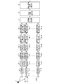
- the array error matrix estimation unit 14 is composed of, for example, a semiconductor integrated circuit on which a CPU is mounted or a one-chip microcomputer, and the arrival directions ⁇ of a plurality of unknown signals estimated by the arrival direction estimation unit 8 and the reference Estimated by the number M of reception antennas 2-1 to 2-M ⁇ arrival direction estimation unit 8 using frequency domain signals x [m, k] normalized by signal normalization units 5-1 to 5-M
- An array error matrix C having a dimension of the number M of arriving directions is calculated, and the amplitude error and phase error of the receiving antennas 2-1 to 2-M are calculated from the array error matrix C for each arrival direction ⁇ of each signal.
- the process which estimates is carried out.
- the array error matrix estimation unit 14 constitutes amplitude phase error estimation means.
- the arrival direction estimation unit 8 estimates the arrival direction ⁇ of unknown signals in the same manner as in the first embodiment, but in this fourth embodiment, the arrival direction ⁇ of M tilde unknown signals can be estimated. It shall be.
- the array error matrix estimation unit 14 and the reference signal normalization units 5-1 to 5 An array error matrix C having a dimension of M ⁇ M tilde is calculated using the frequency domain signal x [m, k] normalized by ⁇ M.
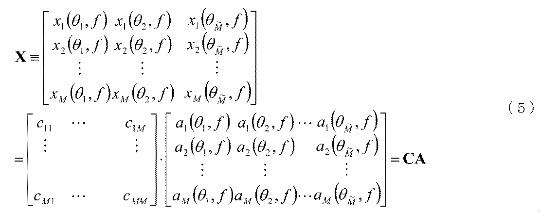
- the frequency domain signal x can be modeled as the following equation (5).
- the array error matrix C can be calculated as follows. After calculating the array error matrix C, the array error matrix estimation unit 14 calculates the amplitude error and phase error of the receiving antennas 2-1 to 2-M from the array error matrix C for each arrival direction ⁇ of each signal.
- the array error matrix estimation unit 14 determines the arrival directions ⁇ of the plurality of unknown signals estimated by the arrival direction estimation unit 8 and the reference signal normalization unit 5-
- the number M of reception antennas 2-1 to 2-M ⁇ the number of arrival directions estimated by the arrival direction estimation unit 8 using the frequency domain signal x [m, k] normalized by 1 to 5-M
- An array error matrix C having a dimension of M tilde is calculated, and the amplitude error and phase error of the receiving antennas 2-1 to 2-M are estimated from the array error matrix C for each arrival direction ⁇ of each signal.
- the arrival direction ⁇ of M tilde unknown signals is estimated by the arrival direction estimation unit 8
- the amplitude error and phase error of the receiving antennas 2-1 to 2-M are calculated for each arrival direction ⁇ of each signal. There is an effect that can be estimated.
- Embodiment 5 FIG.
- the arrival directions ⁇ of the plurality of unknown signals may be estimated.
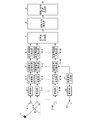
- FIG. 5 is a block diagram showing a calibration apparatus according to Embodiment 5 of the present invention.
- Correlation matrix calculation units 15-1 to 15-M are composed of, for example, a semiconductor integrated circuit mounting a CPU or a one-chip microcomputer, and are normalized by reference signal normalization units 5-1 to 5-M. A process of extracting a plurality of frequency data from the frequency domain signal x [m, k] thus performed and calculating a correlation matrix R of the plurality of frequency data is performed.
- the correlation matrix calculation units 15-1 to 15-M constitute a correlation matrix calculation unit.
- the eigenvector calculation units 16-1 to 16-M are constituted by, for example, a semiconductor integrated circuit mounted with a CPU or a one-chip microcomputer, and the correlation calculated by the correlation matrix calculation units 15-1 to 15-M. From the matrix R, eigenvectors corresponding to a plurality of unknown signals having different directions of arrival received by the receiving antennas 2-1 to 2-M are specified, and the eigenvectors are normalized by the reference signal normalizing units 5-1 to 5-M. A process of outputting the normalized frequency domain signal x [m, k] to the reference frequency normalization units 6-1 to 6-M is performed.
- the eigenvector calculation units 16-1 to 16-M constitute eigenvector specifying means.
- Correlation matrix calculation sections 15-1 to 15-M when the reference signal normalization sections 5-1 to 5-M normalize the frequency domain signals, as in the first embodiment, K tilde frequency data is extracted from x [m, k].
- the correlation matrix calculation units 15-1 to 15-M extract K tilde pieces of frequency data
- the correlation matrix calculation units 15-1 to 15-M calculate a correlation matrix of the frequency data.
- the correlation matrix R xx, m, l of the l-th frequency data can be calculated as in the following equation (7).
- the correlation matrix R xx, m after averaging in the frequency direction can be calculated as in the following equation (8).
- the eigenvector calculation units 16-1 to 16-M expand the eigenvalues of the averaged correlation matrix Rxx, m when the correlation matrix calculation units 15-1 to 15-M average the correlation matrix Rxx, m, l L times.
- the N eigenvectors correspond to the frequency domain signal related to the N-wave received signal.
- the eigenvector calculation units 16-1 to 16-M identify N eigenvectors corresponding to the top N eigenvalues
- the N eigenvectors are normalized by the reference signal normalization units 5-1 to 5-M.
- the frequency domain signal x [m, k] is output to the reference frequency normalization units 6-1 to 6-M.
- the eigenvectors are specified independently for each receiving antenna 2, and eigenvectors having close eigenvalues are associated between the respective receiving antennas 2, thereby estimating the frequency domain signal related to the same direction of arrival ⁇ at each receiving antenna 2. Can do.
- a plurality of frequency data is extracted from the frequency domain signal x [m, k] normalized by the reference signal normalizing units 5-1 to 5-M.
- the correlation matrix calculation units 15-1 to 15-M for calculating the correlation matrix R of a plurality of frequency data and the correlation matrix R of the frequency domain signals calculated by the correlation matrix calculation units 15-1 to 15-M Eigenvectors corresponding to a plurality of unknown signals with different arrival directions received by the receiving antennas 2-1 to 2-M are identified, and the plurality of eigenvectors are normalized by the reference signal normalization units 5-1 to 5-M Since the eigenvector calculation units 16-1 to 16-M output to the reference frequency normalization units 6-1 to 6-M as the frequency domain signal x [m, k] are provided, the plurality of radiation sources 1 Of the radiated unknown signal An effect that it is possible to estimate the coming direction theta.
- Embodiment 6 FIG. In the above first to fifth embodiments, an example is shown in which a signal whose direction of arrival ⁇ is unknown is radiated from the radiation source 1, but the calibration device may have a radar form that radiates a signal itself. .
- the transmission signal generator 21 generates a baseband signal (for example, a linear frequency modulation signal, a code modulation signal, a CW signal, etc.) generally used in radar.
- the transmission unit 22 performs various types of signal processing (for example, signal amplification processing, band-pass filter processing, frequency conversion processing, etc.) on the baseband signal generated by the transmission signal generation unit 21 to generate an RF signal ( This is a transmitter that obtains a transmission signal and outputs the RF signal to the transmission antenna 23.
- the transmission signal generation unit 21 and the transmission unit 22 constitute a signal generation unit.
- the transmission antenna 23 radiates the RF signal output from the transmission unit 22 into space.
- the transmission signal generation unit 21 generates a baseband signal generally used in radar, and outputs the baseband signal to the transmission unit 22. Further, the transmission signal generation unit 21 converts the baseband signal into a frequency domain signal by performing FFT on the baseband signal, and sends the frequency domain signal to the reference signal normalization units 5-1 to 5-M. Output.
- the reference signal normalizing units 5-1 to 5 -M receive any one of the reception antennas 2 out of the frequency domain signals converted by the Fourier transform units 4-1 to 4 -M. However, the frequency domain signal output from the transmission signal generator 21 may be set as the reference signal.
- the transmission unit 22 When receiving the baseband signal from the transmission signal generation unit 21, the transmission unit 22 obtains an RF signal by performing various signal processing on the baseband signal, and outputs the RF signal to the transmission antenna 23. To do. As a result, an RF signal is radiated from the transmitting antenna 23 into space. The RF signal radiated to the space is reflected by a reflector existing in the space and then received by the receiving antennas 2-1 to 2-M. Since the subsequent processing contents are the same as those in the first embodiment, detailed description thereof is omitted.
- the arrival direction estimation unit 8 detects the peak of the beam pattern P ( ⁇ tilde) formed by the broadband beam forming unit 7 so that the signal radiated from the radiation source 1 arrives.
- the amplitude / phase error estimator 9 calculates the arrival direction ⁇ estimated by the arrival direction estimator 8 and the frequency domain signal x normalized by the reference signal normalizers 5-1 to 5-M.
- the estimation of the amplitude error and phase error of the receiving antennas 2-1 to 2-M using [m, k] has been shown, the arrival direction ⁇ of the signal radiated from the radiation source 1 and the receiving antenna 2-
- the amplitude error and the phase error of 1 to 2-M may be estimated simultaneously.
- the iterative calculation units 31-1 to 31-M are composed of, for example, a semiconductor integrated circuit mounted with a CPU or a one-chip microcomputer, and are normalized by the reference signal normalization units 5-1 to 5-M.
- the iterative calculation units 31-1 to 31-M constitute amplitude phase error estimation means.
- the arrival direction averaging unit 32 is composed of, for example, a semiconductor integrated circuit on which a CPU is mounted or a one-chip microcomputer, and the average of the arrival directions ⁇ repeatedly calculated by the iterative calculation units 31-1 to 31-M. Perform the requested process.
- the iterative calculation units 31-1 to 31-M are frequency regions in which the reference signal normalization units 5-1 to 5-M are transformed by the Fourier transform units 4-1 to 4-M.
- the normalized frequency domain signal x [m, k] the steering direction determined by the unknown signal arrival direction ⁇ and the positions of the receiving antennas 2-1 to 2-M, and the steering vector Using the differential value differentiated by the arrival direction ⁇ , a linear equation as shown in the following equation (9) is generated.
- a m ( ⁇ 0 , f) and a m ( ⁇ 0 , f + ⁇ f) in a 2 ⁇ 2 matrix on the right side are steering vectors, and ⁇ a m ( ⁇ 0 , f) / ⁇ ⁇ and ⁇ a m ( ⁇ 0 , f + ⁇ f) / ⁇ are differential values obtained by differentiating the steering vector in the direction of arrival ⁇ .
- the iterative calculation units 31-1 to 31-M When the iterative calculation units 31-1 to 31-M generate a linear equation, the iterative calculation is performed, whereby the arrival direction ⁇ of the unknown signal and the complex amplitudes ⁇ m (f of the receiving antennas 2-1 to 2-M are calculated. ) Amplitude error and phase error are estimated simultaneously.
- the arrival direction averaging unit 32 obtains the average of the arrival directions ⁇ .
- the iterative calculation units 31-1 to 31-M perform the frequency domain signal x [normalized by the reference signal normalization units 5-1 to 5-M. m, k], a steering vector determined from the arrival direction ⁇ of the unknown signal and the position of the receiving antennas 2-1 to 2-M, and a differential value obtained by differentiating the steering vector by the arrival direction ⁇ .
- the configuration is such that iterative calculation of the amplitude error and the phase error that are the complex amplitudes ⁇ m (f) of the receiving antennas 2-1 to 2-M together with the direction ⁇ is performed, as in the first embodiment, Estimate amplitude error and phase error of multiple receiving antennas 2-1 to 2-M while accurately estimating arrival direction ⁇ of unknown signal without preparing radiation sources with known arrival directions in advance The effect which can be done is produced.
- This invention is a calibration that needs to compensate for the amplitude error and phase error without preparing a radiation source whose direction of arrival is known in advance, even if the amplitude error and phase error of each antenna change over time. Suitable for equipment.
Landscapes
- Engineering & Computer Science (AREA)
- Computer Networks & Wireless Communication (AREA)
- Signal Processing (AREA)
- Physics & Mathematics (AREA)
- Electromagnetism (AREA)
- Variable-Direction Aerials And Aerial Arrays (AREA)
- Radio Transmission System (AREA)
Abstract
Description
以下の非特許文献1に開示されているキャリブレーション装置では、各アンテナと受信部の間からキャリブレーション用の信号を注入して、各受信部から出力されたキャリブレーション用の信号を抽出し、それらのキャリブレーション用の信号を比較することで、各アンテナの振幅誤差と位相誤差を推定するキャリブレーション方法を用いている。
しかし、このキャリブレーション方法では、アンテナ本体が有する誤差を排除することができない。また、各アンテナの振幅誤差や位相誤差は経年変化するため、定期的にキャリブレーション用の信号を注入して比較する仕組みが必要になる。
しかし、このキャリブレーション方法では、到来方向が既知である放射源を複数用意する必要がある。また、各アンテナの振幅誤差や位相誤差の経年変化に対処するには、定期的に上記の推定処理を繰り返し実施する必要がある。
この手法では、各アンテナの振幅誤差や位相誤差が角度依存性を持たないという前提の下で、アレー素子数×アレー素子数の次元で表されるアレー誤差行列が受信信号に乗算されているモデルを生成し、そのアレー誤差行列を推定することでキャブレーションを実施している。
しかし、この手法では、アレー誤差行列が対角行列であるという仮定をおいており、実際には、センサ周辺の複雑な反射環境下では、上記の仮定が成立しないことが非特許文献1で述べられている。
また、各アンテナの振幅誤差や位相誤差の経年変化に対処するには、未知の放射源から放射される信号の到来方向を推定する処理とは別個に、上記の誤差の推定処理を定期的に繰り返す必要がある課題があった。
実施の形態1.
図1はこの発明の実施の形態1によるキャリブレーション装置を示す構成図である。
図1において、放射源1は到来方向θが未知の信号を放射している信号源、あるいは、他の放射源から放射された信号を反射している反射体である。
受信アンテナ2-1~2-Mはアレーアンテナを構成している素子アンテナであり、到来方向θが未知の信号を受信する。
受信部3-1~3-Mは受信アンテナ2-1~2-Mの受信信号であるRF信号に対して、各種の信号処理(例えば、信号の増幅処理、帯域通過フィルタ処理、周波数変換処理、A/D変換処理など)を実施することで、デジタル信号であるベースバンド複素信号を得て、そのベースバンド複素信号をフーリエ変換部4-1~4-Mに出力する受信機である。
なお、受信部3-1~3-Mにより得られたデジタル信号がIF実信号である場合、そのIF実信号に対するヒルベルト変換やデジタル直交検波を実施することで、ベースバンド複素信号を得る構成にしてもよい。
なお、受信部3-1~3-M及びフーリエ変換部4-1~4-Mから信号変換手段が構成されている。
ここでは、ベースバンド複素信号をFFTしているが、ベースバンド複素信号を周波数領域信号に変換する処理であれば、FFTに限るものではなく、例えば、ベースバンド複素信号をDFT(Discrete Fourier Transform:離散フーリエ変換)するようにしてもよい。
ここでは、いずれか1つの受信アンテナ2に係る周波数領域信号を参照信号に設定しているが、放射源1から放射される信号の周波数スペクトルを事前に取得している場合には、その周波数スペクトルを参照信号に設定するようにしてもよい。
到来方向推定部8は広帯域ビーム形成部7により形成されたビームパターンのピークを検出することで、放射源1から放射された信号の到来方向θを推定する処理を実施する。
なお、広帯域ビーム形成部7及び到来方向推定部8から到来方向推定手段が構成されている。
例えば、受信アンテナ2-1~2-Mと受信部3-1~3-Mを除く構成要素をコンピュータで構成する場合、フーリエ変換部4-1~4-M、参照信号正規化部5-1~5-M、基準周波数正規化部6-1~6-M、広帯域ビーム形成部7、到来方向推定部8及び振幅・位相誤差推定部9の処理内容を記述しているプログラムをコンピュータのメモリに格納し、当該コンピュータのCPUが当該メモリに格納されているプログラムを実行するようにすればよい。
アレーアンテナを構成している受信アンテナ2-1~2-Mは、放射源1から放射された到来方向θが未知の信号を受信する。
受信部3-1~3-Mは、受信アンテナ2-1~2-Mの受信信号であるRF信号に対して、各種の信号処理(例えば、信号の増幅処理、帯域通過フィルタ処理、周波数変換処理、A/D変換処理など)を実施することで、デジタル信号であるベースバンド複素信号を得て、そのベースバンド複素信号をフーリエ変換部4-1~4-Mに出力する。
参照信号正規化部5-1~5-Mは、フーリエ変換部4-1~4-Mから周波数領域信号を受けると、放射源1の周波数スペクトルの影響を除去するため、フーリエ変換部4-1~4-Mにより変換されたM個の周波数領域信号のうち、いずれか1つの受信アンテナ2に係る周波数領域信号を参照信号に設定し、その参照信号でフーリエ変換部4-1~4-Mにより変換された周波数領域信号を除算することで、その周波数領域信号を正規化する。
ここでは、いずれか1つの受信アンテナ2に係る周波数領域信号を参照信号に設定しているが、放射源1から放射される信号の周波数スペクトルを事前に取得している場合には、その周波数スペクトルを参照信号に設定し、その参照信号でフーリエ変換部4-1~4-Mにより変換された周波数領域信号を除算することで、その周波数領域信号を正規化するようにしてもよい。

また、γm(f)は周波数fにおけるm番目の受信アンテナ2-mの複素振幅であり、受信アンテナ2-mの振幅誤差と位相誤差を意味する。
fcは放射源1から放射された信号の中心周波数、dは受信アンテナ2-1~2-Mの素子間隔、cは光速、θは放射源1から放射された信号の到来方向、n[m,k]は周波数インデックスkにおけるm番目の受信アンテナ2-mの受信信号に含まれている受信機雑音である。
ここでは説明の簡略化のために、受信アンテナ2-1~2-Mの素子間隔dが等間隔であって、受信アンテナ2-1~2-Mが直線上に並んでいることを想定しているが、受信アンテナ2-1~2-Mの素子間隔が不等間隔であってもよいし、受信アンテナ2-1~2-Mが2次元に配置されているものであってもよい。
ここで、周波数領域信号x[m,k]の帯域内において、複素振幅γm(f)が一定であるとすれば、上記の式(1)は、下記の式(2)のように表される。


なお、明細書の文書中では、電子出願の関係上、文字の上に“~”の記号を付することができないので、xチルダのように表記している。
以下、式(3)の右辺第一項を「正規化ステアリングベクトル」と称する。式(3)では、受信アンテナ2-1~2-Mの複素振幅と位相誤差の影響が除去されており、未知パラメータは放射源1から放射されている信号の到来方向θだけとなっている。
即ち、広帯域ビーム形成部7は、下記の式(4)に示すように、正規化ステアリングベクトル(式(3)の右辺第一項)を利用し、到来方向θを変化させることで広帯域のビームパターンを形成する。

また、aチルダm,k(θ)は正規化ステアリングベクトル、Hは複素共役転置を意味する。
到来方向推定部8は、ビームパターンP(θチルダ)のピークを検出すると、そのピークに対応する方向を特定し、そのピークに対応する方向を放射源1から放射された信号の到来方向θとして振幅・位相誤差推定部9に出力する。
なお、複素振幅γm(f)の推定には、例えば、最小二乗法等が適用される。複素振幅γm(f)の絶対値から振幅誤差を推定することができ、また、複素振幅γm(f)の位相から位相誤差を推定することができる。
上記実施の形態1では、受信アンテナ2-1~2-Mの受信信号の帯域内で、受信アンテナ2-1~2-Mの振幅誤差と位相誤差が一定であるものについて説明しているが、その受信信号の帯域内で、受信アンテナ2-1~2-Mの振幅誤差と位相誤差が一定でない場合もある。
この実施の形態2では、受信アンテナ2-1~2-Mの受信信号の帯域内で、受信アンテナ2-1~2-Mの振幅誤差と位相誤差が一定でない場合でも、受信アンテナ2-1~2-Mの振幅誤差と位相誤差を高精度に推定することができるキャリブレーション装置について説明する。
帯域分割部11-1~11-Mは例えばCPUを実装している半導体集積回路、あるいは、ワンチップマイコンなどから構成されており、参照信号正規化部5-1~5-Mにより正規化された周波数領域信号x[m,k]を複数の帯域に分割する処理を実施する。なお、帯域分割部11-1~11-Mは帯域分割手段を構成している。
基準周波数正規化部12-1~12-Mは例えばCPUを実装している半導体集積回路、あるいは、ワンチップマイコンなどから構成されており、帯域分割部11-1~11-Mにより分割された帯域毎に、当該帯域内の周波数領域信号に含まれている基準となる周波数の信号を用いて、当該帯域内の周波数領域信号を正規化する処理を実施する。なお、基準周波数正規化部12-1~12-Mは基準周波数正規化手段を構成している。
帯域分割部11-1~11-Mは、上記実施の形態1と同様にして、参照信号正規化部5-1~5-Mがフーリエ変換部4-1~4-Mにより変換された周波数領域信号を正規化して、正規化後の周波数領域信号x[m,k]を出力すると、その周波数領域信号x[m,k]を複数の帯域に分割する。
周波数領域信号x[m,k]を分割する帯域の幅は、実際のシステム毎に異なり、受信アンテナ2-1~2-M及び受信部3-1~3-Mにおける振幅誤差及び位相誤差の周波数特性によって決定される。分割する帯域の幅は、事前のシミュレーション計算で求める方法のほか、実際にアナログ信号を注入して計測する方法などが考えられる。
基準周波数正規化部12-1~12-Mは、基準となる周波数を決定すると、帯域分割部11-1~11-Mにより分割された帯域毎に、その決定した基準となる周波数の信号で、当該分割帯域内の周波数領域信号を除算することで、当該分割帯域内の周波数領域信号を正規化する。
広帯域ビーム形成部7は、基準周波数正規化部6-1~6-Mにより正規化された各分割帯域の周波数領域信号を用いて、広帯域のビームパターンを形成する。
以降の処理内容は、上記実施の形態1と同様であるため詳細な説明を省略する。
上記実施の形態1,2では、受信部3-1~3-Mが受信アンテナ2-1~2-Mの受信信号からベースバンド複素信号を得て、フーリエ変換部4-1~4-Mがベースバンド複素信号をFFTすることで、そのベースバンド複素信号を周波数領域信号に変換しているが、その受信信号のSNR(信号対雑音電力比)が低い場合には、その周波数領域信号を高精度に求めることができない。
また、参照信号正規化部5-1~5-Mが周波数領域信号を正規化する際、放射源1から放射された信号の周波数スペクトル内に、0に近い成分が含まれる場合には雑音成分が増幅されることがある。
そこで、この実施の形態2では、受信アンテナ2-1~2-Mの受信信号のSNRを高めて、周波数領域信号を高精度に求めることができるキャリブレーション装置について説明する。
相互相関算出部13-1~13-Mは例えばCPUを実装している半導体集積回路、あるいは、ワンチップマイコンなどから構成されており、受信部3-1~3-Mから出力されたベースバンド複素信号のうち、いずれか1つの受信アンテナ2に係るベースバンド複素信号を基準信号に設定して、受信部3-1~3-Mから出力されたベースバンド複素信号と前記基準信号の相互相関を算出し、その相互相関結果を用いて、受信部3-1~3-Mから出力されたベースバンド複素信号のSNRを高めるSNR改善処理を実施し、SNR改善処理後のベースバンド複素信号をフーリエ変換部4-1~4-Mに出力する処理を実施する。なお、相互相関算出部13-1~13-Mは相互相関算出手段を構成している。
ここでは、いずれか1つの受信アンテナ2に係るベースバンド複素信号を基準信号に設定しているが、放射源1から放射される信号のベースバンド複素信号を事前に取得している場合には、そのベースバンド複素信号を基準信号に設定するようにしてもよい。
相互相関算出部13-1~13-Mは、上記実施の形態1と同様にして、受信部3-1~3-Mがベースバンド複素信号を出力すると、いずれか1つの受信アンテナ2に係るベースバンド複素信号を基準信号に設定し、受信部3-1~3-Mから出力されたベースバンド複素信号と前記基準信号の相互相関を算出する。
この相互相関は、時間領域における畳み込み演算で計算してもよいが、演算量の低減のために、周波数領域における乗算として計算するようにしてもよい。
ここでは、いずれか1つの受信アンテナ2に係るベースバンド複素信号を基準信号に設定しているが、放射源1から放射される信号のベースバンド複素信号を事前に取得している場合には、そのベースバンド複素信号を基準信号に設定するようにしてもよい。
相互相関算出部13-1~13-Mは、相互相関値の絶対値のピークを検出すると、ベースバンド複素信号におけるピーク周辺の信号(高SNRの信号)をフーリエ変換部4-1~4-Mに出力する。
なお、ピーク周辺を抽出した後に0詰めを行って周波数ポイント数を増加させる構成としてもよい。
また、フーリエ変換部4-1~4-Mにより変換される周波数領域信号を平滑化することができるため、参照信号正規化部5-1~5-Mが周波数領域信号を正規化する際に生じる雑音の増幅を抑圧することができる効果を奏する。
上記実施の形態1~3では、1つの放射源1から放射された到来方向θが未知の信号を受信して、その到来方向θと受信アンテナ2-1~2-Mの振幅誤差及び位相誤差を推定するものを示したが、複数の放射源1から放射された信号の到来方向θを推定するとともに、各信号の到来方向θ毎に、受信アンテナ2-1~2-Mの振幅誤差及び位相誤差を推定するようにしてもよい。
アレー誤差行列推定部14は例えばCPUを実装している半導体集積回路、あるいは、ワンチップマイコンなどから構成されており、到来方向推定部8により推定された複数の未知信号の到来方向θと、参照信号正規化部5-1~5-Mにより正規化された周波数領域信号x[m,k]とを用いて、受信アンテナ2-1~2-Mの本数M×到来方向推定部8により推定された到来方向の数Mチルダの次元を有するアレー誤差行列Cを算出し、各信号の到来方向θ毎に、そのアレー誤差行列Cから受信アンテナ2-1~2-Mの振幅誤差及び位相誤差を推定する処理を実施する。なお、アレー誤差行列推定部14は振幅位相誤差推定手段を構成している。
到来方向推定部8は、上記実施の形態1と同様の方法で、未知信号の到来方向θを推定するが、この実施の形態4では、Mチルダ個の未知信号の到来方向θを推定できているものとする。
アレー誤差行列推定部14は、到来方向推定部8がMチルダ個の未知信号の到来方向θを推定すると、Mチルダ個の未知信号の到来方向θと、参照信号正規化部5-1~5-Mにより正規化された周波数領域信号x[m,k]とを用いて、M×Mチルダの次元を有するアレー誤差行列Cを算出する。

上記実施の形態1~3では、フーリエ変換部4-1~4-Mがベースバンド複素信号をFFTする時間の範囲内で、到来方向θを推定する未知の信号が1波だけ入射される例を説明しているが、到来方向θを推定する未知の信号が複数波入射される場合、複数の未知の信号の到来方向θを推定するようにしてもよい。
相関行列算出部15-1~15-Mは例えばCPUを実装している半導体集積回路、あるいは、ワンチップマイコンなどから構成されており、参照信号正規化部5-1~5-Mにより正規化された周波数領域信号x[m,k]から複数の周波数データを抽出して、複数の周波数データの相関行列Rを算出する処理を実施する。なお、相関行列算出部15-1~15-Mは相関行列算出手段を構成している。
相関行列算出部15-1~15-Mは、上記実施の形態1と同様に、参照信号正規化部5-1~5-Mが周波数領域信号を正規化すると、正規化後の周波数領域信号x[m,k]から、例えばKチルダ個の周波数データを抽出する。
相関行列算出部15-1~15-Mは、Kチルダ個の周波数データを抽出すると、それらの周波数データの相関行列を算出する。
例えば、l番目の周波数データの相関行列Rxx,m,lは、下記の式(7)のように算出することができる。

周波数方向平均後の相関行列Rxx,mは、下記の式(8)のように算出することができる。

例えば、N波の受信信号が同時に入射されている状況下では、平均後の相関行列Rxx,mの固有値の中で、値が大きい上位N個の固有値を特定して、上位N個の固有値に対応するN個の固有ベクトルを特定する。N個の固有ベクトルは、N波の受信信号に係る周波数領域信号に対応している。
固有ベクトル算出部16-1~16-Mは、上位N個の固有値に対応するN個の固有ベクトルを特定すると、N個の固有ベクトルを参照信号正規化部5-1~5-Mにより正規化された周波数領域信号x[m,k]として基準周波数正規化部6-1~6-Mに出力する。
なお、固有ベクトルの特定は、受信アンテナ2毎に独立に行い、固有値が近い固有ベクトルを各受信アンテナ2の間で対応させることで、各受信アンテナ2で同じ到来方向θに関する周波数領域信号を推定することができる。
上記実施の形態1~5では、放射源1から到来方向θが未知の信号を放射される例を示しているが、キャリブレーション装置が自ら信号を放射するレーダの形態を有していてもよい。
送信信号生成部21はレーダで一般的に用いられるベースバンド信号(例えば、線形周波数変調信号、符号変調信号、CW信号など)を生成する。
送信部22は送信信号生成部21により生成されたベースバンド信号に対して、各種の信号処理(例えば、信号の増幅処理、帯域通過フィルタ処理、周波数変換処理など)を実施することでRF信号(送信信号)を得て、そのRF信号を送信アンテナ23に出力する送信機である。なお、送信信号生成部21及び送信部22から信号生成手段が構成されている。
送信アンテナ23は送信部22から出力されたRF信号を空間に放射する。
送信信号生成部21は、レーダで一般的に用いられるベースバンド信号を生成し、そのベースバンド信号を送信部22に出力する。
また、送信信号生成部21は、そのベースバンド信号をFFTすることで、そのベースバンド信号を周波数領域の信号に変換し、その周波数領域信号を参照信号正規化部5-1~5-Mに出力する。
参照信号正規化部5-1~5-Mは、上記実施の形態1と同様に、フーリエ変換部4-1~4-Mにより変換された周波数領域信号のうち、いずれか1つの受信アンテナ2に係る周波数領域信号を参照信号に設定するようにしてもよいが、送信信号生成部21から出力された周波数領域信号を参照信号に設定するようにしてもよい。
これにより、送信アンテナ23からRF信号が空間に放射される。空間に放射されたRF信号は、空間に存在している反射体に反射されたのち、受信アンテナ2-1~2-Mで受信される。
以降の処理内容は、上記実施の形態1と同様であるため詳細な説明を省略する。
上記実施の形態1~6では、到来方向推定部8が、広帯域ビーム形成部7により形成されたビームパターンP(θチルダ)のピークを検出することで、放射源1から放射された信号の到来方向θを推定したのち、振幅・位相誤差推定部9が、到来方向推定部8により推定された到来方向θと参照信号正規化部5-1~5-Mにより正規化された周波数領域信号x[m,k]を用いて、受信アンテナ2-1~2-Mの振幅誤差及び位相誤差を推定するものを示したが、放射源1から放射された信号の到来方向θと受信アンテナ2-1~2-Mの振幅誤差及び位相誤差を同時に推定するようにしてもよい。
反復計算部31-1~31-Mは例えばCPUを実装している半導体集積回路、あるいは、ワンチップマイコンなどから構成されており、参照信号正規化部5-1~5-Mにより正規化された周波数領域信号x[m,k]と、未知の信号の到来方向θと受信アンテナ2-1~2-Mの位置から決まるステアリングベクトルと、そのステアリングベクトルを到来方向θで微分した微分値とを用いて、その到来方向θと一緒に受信アンテナ2-1~2-Mの複素振幅γm(f)である振幅誤差及び位相誤差の反復計算を実施する。なお、反復計算部31-1~31-Mは振幅位相誤差推定手段を構成している。
到来方向平均部32は例えばCPUを実装している半導体集積回路、あるいは、ワンチップマイコンなどから構成されており、反復計算部31-1~31-Mにより反復計算された到来方向θの平均を求める処理を実施する。
反復計算部31-1~31-Mは、上記実施の形態1と同様に、参照信号正規化部5-1~5-Mがフーリエ変換部4-1~4-Mにより変換された周波数領域信号を正規化すると、正規化後の周波数領域信号x[m,k]と、未知の信号の到来方向θと受信アンテナ2-1~2-Mの位置から決まるステアリングベクトルと、そのステアリングベクトルを到来方向θで微分した微分値とを用いて、下記の式(9)に示すような線形方程式を生成する。

到来方向平均部32は、反復計算部31-1~31-Mが未知の信号の到来方向θを推定すると、それらの到来方向θの平均を求める。
Claims (7)
- 到来方向が未知の信号を受信するアレーアンテナと、
前記アレーアンテナを構成している複数の素子アンテナの受信信号を周波数領域の信号に変換する信号変換手段と、
前記信号変換手段により変換された複数の周波数領域の信号のうち、いずれか1つの素子アンテナに係る周波数領域の信号又は事前に取得している前記未知の信号の周波数スペクトルを参照信号に設定し、前記参照信号を用いて、前記複数の周波数領域の信号を正規化する参照信号正規化手段と、
前記参照信号正規化手段により正規化された複数の周波数領域の信号に含まれている基準となる周波数の信号を用いて、前記参照信号正規化手段により正規化された複数の周波数領域の信号を正規化する基準周波数正規化手段と、
前記基準周波数正規化手段により正規化された複数の周波数領域の信号を用いて、前記未知の信号の到来方向を推定する到来方向推定手段と、
前記到来方向推定手段により推定された到来方向と前記参照信号正規化手段により正規化された複数の周波数領域の信号を用いて、前記複数のアンテナの振幅誤差及び位相誤差を推定する振幅位相誤差推定手段と
を備えたキャリブレーション装置。 - 前記参照信号正規化手段により正規化された複数の周波数領域の信号を複数の帯域に分割する帯域分割手段を備え、
前記基準周波数正規化手段は、前記帯域分割手段により分割された帯域毎に、当該帯域内の周波数領域の信号に含まれている基準となる周波数の信号を用いて、当該帯域内の周波数領域の信号を正規化することを特徴とする請求項1記載のキャリブレーション装置。 - 前記複数の素子アンテナの受信信号のうち、いずれか1つの受信信号又は事前に取得している前記未知の信号を基準信号に設定して、前記複数の素子アンテナの受信信号と前記基準信号の相互相関を算出し、その相互相関結果を用いて、前記受信信号の信号対雑音電力比を高めるSNR改善処理を実施し、SNR改善処理後の受信信号を前記信号変換手段に出力する相互相関算出手段を備えたことを特徴とする請求項1記載のキャリブレーション装置。
- 前記到来方向推定手段は、前記アレーアンテナにより受信された到来方向が異なる複数の未知信号の到来方向を推定し、
前記振幅位相誤差推定手段は、前記到来方向推定手段により推定された複数の未知信号の到来方向と前記参照信号正規化手段により正規化された複数の周波数領域の信号を用いて、前記アレーアンテナを構成している素子アンテナの数×前記到来方向推定手段により推定された到来方向の数の次元を有するアレー誤差行列を算出し、前記アレー誤差行列から前記複数のアンテナの振幅誤差及び位相誤差を推定することを特徴とする請求項1記載のキャリブレーション装置。 - 前記参照信号正規化手段により正規化された周波数領域の信号から複数の周波数データを抽出して、前記複数の周波数データの相関行列を算出する相関行列算出手段と、
前記相関行列算出手段により算出された相関行列から、前記アレーアンテナにより受信された到来方向が異なる複数の未知信号に対応する固有ベクトルを特定し、前記固有ベクトルを前記参照信号正規化手段により正規化された周波数領域の信号として前記基準周波数正規化手段に出力する固有ベクトル特定手段とを備えたことを特徴とする請求項1記載のキャリブレーション装置。 - 送信信号を生成する信号生成手段と、
前記信号生成手段により生成された送信信号を空間に放射する送信アンテナとを備え、
前記アレーアンテナは、前記送信アンテナから放射されたのち、前記空間に存在している反射体に反射された前記送信信号の反射波を受信することを特徴とする請求項1記載のキャリブレーション装置。 - 到来方向が未知の信号を受信するアレーアンテナと、
前記アレーアンテナを構成している複数の素子アンテナの受信信号を周波数領域の信号に変換する信号変換手段と、
前記信号変換手段により変換された複数の周波数領域の信号のうち、いずれか1つの素子アンテナに係る周波数領域の信号又は事前に取得している前記未知の信号の周波数スペクトルを参照信号に設定し、前記参照信号を用いて、前記複数の周波数領域の信号を正規化する参照信号正規化手段と、
前記参照信号正規化手段により正規化された複数の周波数領域の信号と、前記未知の信号の到来方向と前記複数の素子アンテナの位置から決まるステアリングベクトルと、前記ステアリングベクトルを前記到来方向で微分した微分値とを用いて、前記到来方向と一緒に前記複数のアンテナの振幅誤差及び位相誤差を反復計算する振幅位相誤差推定手段と
を備えたキャリブレーション装置。
Priority Applications (5)
| Application Number | Priority Date | Filing Date | Title |
|---|---|---|---|
| PCT/JP2014/062600 WO2015173861A1 (ja) | 2014-05-12 | 2014-05-12 | キャリブレーション装置 |
| JP2016514179A JP5992129B2 (ja) | 2014-05-12 | 2014-05-12 | キャリブレーション装置 |
| US15/303,257 US9716557B2 (en) | 2014-05-12 | 2014-05-12 | Calibration device |
| CA2948539A CA2948539C (en) | 2014-05-12 | 2014-05-12 | Calibration device |
| EP14891842.8A EP3145093B1 (en) | 2014-05-12 | 2014-05-12 | Calibration device |
Applications Claiming Priority (1)
| Application Number | Priority Date | Filing Date | Title |
|---|---|---|---|
| PCT/JP2014/062600 WO2015173861A1 (ja) | 2014-05-12 | 2014-05-12 | キャリブレーション装置 |
Publications (1)
| Publication Number | Publication Date |
|---|---|
| WO2015173861A1 true WO2015173861A1 (ja) | 2015-11-19 |
Family
ID=54479435
Family Applications (1)
| Application Number | Title | Priority Date | Filing Date |
|---|---|---|---|
| PCT/JP2014/062600 Ceased WO2015173861A1 (ja) | 2014-05-12 | 2014-05-12 | キャリブレーション装置 |
Country Status (5)
| Country | Link |
|---|---|
| US (1) | US9716557B2 (ja) |
| EP (1) | EP3145093B1 (ja) |
| JP (1) | JP5992129B2 (ja) |
| CA (1) | CA2948539C (ja) |
| WO (1) | WO2015173861A1 (ja) |
Cited By (1)
| Publication number | Priority date | Publication date | Assignee | Title |
|---|---|---|---|---|
| JP2020139876A (ja) * | 2019-02-28 | 2020-09-03 | 株式会社デンソーテン | レーダ装置および補正値算出方法 |
Families Citing this family (3)
| Publication number | Priority date | Publication date | Assignee | Title |
|---|---|---|---|---|
| US20180052227A1 (en) * | 2016-08-16 | 2018-02-22 | GM Global Technology Operations LLC | Beam pattern diversity-based target location estimation |
| CN109309533B (zh) * | 2018-09-04 | 2021-05-18 | 华为技术有限公司 | 一种校准方法及设备 |
| KR20200097101A (ko) * | 2019-02-07 | 2020-08-18 | 현대모비스 주식회사 | 차량용 레이더 장치 및 그 제어 방법 |
Citations (3)
| Publication number | Priority date | Publication date | Assignee | Title |
|---|---|---|---|---|
| JP2007005974A (ja) * | 2005-06-22 | 2007-01-11 | Fujitsu Ltd | 無線通信装置及び位相バラツキ補正方法 |
| JP2007304118A (ja) * | 2007-07-27 | 2007-11-22 | Toshiba Corp | 到来方向推定装置、到来方向推定方法及び障害物推定装置 |
| JP2014003430A (ja) * | 2012-06-18 | 2014-01-09 | Nippon Telegr & Teleph Corp <Ntt> | 追尾アンテナ装置および送信位相補償方法 |
Family Cites Families (6)
| Publication number | Priority date | Publication date | Assignee | Title |
|---|---|---|---|---|
| KR100749451B1 (ko) * | 2005-12-02 | 2007-08-14 | 한국전자통신연구원 | Ofdm 기지국 시스템에서의 스마트 안테나 빔 형성 방법및 장치 |
| JP5186748B2 (ja) * | 2006-09-29 | 2013-04-24 | 富士通株式会社 | 無線通信装置および無線通信方法 |
| US8193971B2 (en) * | 2008-11-10 | 2012-06-05 | Motorola Mobility, Inc. | Antenna reciprocity calibration |
| GB2467773B (en) * | 2009-02-13 | 2012-02-01 | Socowave Technologies Ltd | Communication system, apparatus and methods for calibrating an antenna array |
| WO2013191514A1 (en) * | 2012-06-21 | 2013-12-27 | Samsung Electronics Co., Ltd. | Communication device and orientation control method |
| WO2015066883A1 (en) * | 2013-11-08 | 2015-05-14 | Telefonaktiebolaget L M Ericsson (Publ) | Radio unit with internal parallel antenna calibration |
-
2014
- 2014-05-12 US US15/303,257 patent/US9716557B2/en not_active Expired - Fee Related
- 2014-05-12 CA CA2948539A patent/CA2948539C/en active Active
- 2014-05-12 JP JP2016514179A patent/JP5992129B2/ja active Active
- 2014-05-12 WO PCT/JP2014/062600 patent/WO2015173861A1/ja not_active Ceased
- 2014-05-12 EP EP14891842.8A patent/EP3145093B1/en not_active Not-in-force
Patent Citations (3)
| Publication number | Priority date | Publication date | Assignee | Title |
|---|---|---|---|---|
| JP2007005974A (ja) * | 2005-06-22 | 2007-01-11 | Fujitsu Ltd | 無線通信装置及び位相バラツキ補正方法 |
| JP2007304118A (ja) * | 2007-07-27 | 2007-11-22 | Toshiba Corp | 到来方向推定装置、到来方向推定方法及び障害物推定装置 |
| JP2014003430A (ja) * | 2012-06-18 | 2014-01-09 | Nippon Telegr & Teleph Corp <Ntt> | 追尾アンテナ装置および送信位相補償方法 |
Non-Patent Citations (1)
| Title |
|---|
| See also references of EP3145093A4 * |
Cited By (2)
| Publication number | Priority date | Publication date | Assignee | Title |
|---|---|---|---|---|
| JP2020139876A (ja) * | 2019-02-28 | 2020-09-03 | 株式会社デンソーテン | レーダ装置および補正値算出方法 |
| JP7248454B2 (ja) | 2019-02-28 | 2023-03-29 | 株式会社デンソーテン | レーダ装置および補正値算出方法 |
Also Published As
| Publication number | Publication date |
|---|---|
| JP5992129B2 (ja) | 2016-09-14 |
| US20170033876A1 (en) | 2017-02-02 |
| US9716557B2 (en) | 2017-07-25 |
| EP3145093B1 (en) | 2019-02-13 |
| CA2948539C (en) | 2017-09-05 |
| EP3145093A4 (en) | 2017-12-20 |
| JPWO2015173861A1 (ja) | 2017-04-20 |
| EP3145093A1 (en) | 2017-03-22 |
| CA2948539A1 (en) | 2015-11-19 |
Similar Documents
| Publication | Publication Date | Title |
|---|---|---|
| KR102449214B1 (ko) | 도래각 추정 장치 및 이를 이용한 도래각 추정 방법 | |
| US9507018B2 (en) | Detection and ranging apparatus and ranging method | |
| JP6395677B2 (ja) | 到来方向推定装置 | |
| JP5675285B2 (ja) | レーダ装置 | |
| US20170212205A1 (en) | Angle of arrival estimation | |
| JP5617334B2 (ja) | レーダ装置及び目標探知方法 | |
| JP5992129B2 (ja) | キャリブレーション装置 | |
| CN103064056A (zh) | 一种干扰环境下的天线阵列阵元位置误差测定方法 | |
| JP2009529660A (ja) | 強度が低い、またはサンプルサイズが小さいシナリオでの到来方向推定方法およびそのシステム | |
| CN106486769A (zh) | 用于线性相控阵天线的空间插值方法和设备 | |
| JP2020139876A (ja) | レーダ装置および補正値算出方法 | |
| Tayem et al. | Hardware implementation of a proposed Qr-Tls DOA estimation method and Music, ESPRIT Algorithms on Ni-Pxi platform | |
| JP6246338B2 (ja) | 測角装置及び測角方法 | |
| JP5705066B2 (ja) | パッシブレーダ装置 | |
| CN104360338B (zh) | 一种基于对角加载的阵列天线自适应波束形成方法 | |
| JP7012914B1 (ja) | アレーアンテナの校正装置および校正方法 | |
| You et al. | A novel DOA estimation algorithm of cyclostationary signal based on UCA in impulsive noise | |
| Tayem | Real time implemenation for DOA estimation methods on Ni-Pxi platform | |
| JP2017152872A (ja) | 無線通信装置およびキャリブレーション方法 | |
| JP6030012B2 (ja) | 方位測定装置、方位測定プログラム及び方位測定方法 | |
| JP2004150842A (ja) | 測角方法及びその装置 | |
| JP2016138829A (ja) | 到来方向推定装置 | |
| WO2021131601A1 (ja) | レーダ装置 | |
| JP6200082B2 (ja) | 電波監視装置 | |
| Zhen et al. | DOA estimation for mixed signals with gain-phase error array |
Legal Events
| Date | Code | Title | Description |
|---|---|---|---|
| 121 | Ep: the epo has been informed by wipo that ep was designated in this application |
Ref document number: 14891842 Country of ref document: EP Kind code of ref document: A1 |
|
| ENP | Entry into the national phase |
Ref document number: 2016514179 Country of ref document: JP Kind code of ref document: A |
|
| WWE | Wipo information: entry into national phase |
Ref document number: 15303257 Country of ref document: US |
|
| ENP | Entry into the national phase |
Ref document number: 2948539 Country of ref document: CA |
|
| NENP | Non-entry into the national phase |
Ref country code: DE |
|
| REEP | Request for entry into the european phase |
Ref document number: 2014891842 Country of ref document: EP |
|
| WWE | Wipo information: entry into national phase |
Ref document number: 2014891842 Country of ref document: EP |