WO2015174146A1 - 撮像システム - Google Patents
撮像システム Download PDFInfo
- Publication number
- WO2015174146A1 WO2015174146A1 PCT/JP2015/059479 JP2015059479W WO2015174146A1 WO 2015174146 A1 WO2015174146 A1 WO 2015174146A1 JP 2015059479 W JP2015059479 W JP 2015059479W WO 2015174146 A1 WO2015174146 A1 WO 2015174146A1
- Authority
- WO
- WIPO (PCT)
- Prior art keywords
- led
- light
- emitting element
- deterioration
- lighting time
- Prior art date
- Legal status (The legal status is an assumption and is not a legal conclusion. Google has not performed a legal analysis and makes no representation as to the accuracy of the status listed.)
- Ceased
Links
Images



Classifications
-
- A—HUMAN NECESSITIES
- A61—MEDICAL OR VETERINARY SCIENCE; HYGIENE
- A61B—DIAGNOSIS; SURGERY; IDENTIFICATION
- A61B1/00—Instruments for performing medical examinations of the interior of cavities or tubes of the body by visual or photographical inspection, e.g. endoscopes; Illuminating arrangements therefor
- A61B1/06—Instruments for performing medical examinations of the interior of cavities or tubes of the body by visual or photographical inspection, e.g. endoscopes; Illuminating arrangements therefor with illuminating arrangements
- A61B1/0638—Instruments for performing medical examinations of the interior of cavities or tubes of the body by visual or photographical inspection, e.g. endoscopes; Illuminating arrangements therefor with illuminating arrangements providing two or more wavelengths
-
- A—HUMAN NECESSITIES
- A61—MEDICAL OR VETERINARY SCIENCE; HYGIENE
- A61B—DIAGNOSIS; SURGERY; IDENTIFICATION
- A61B1/00—Instruments for performing medical examinations of the interior of cavities or tubes of the body by visual or photographical inspection, e.g. endoscopes; Illuminating arrangements therefor
- A61B1/00002—Operational features of endoscopes
- A61B1/00004—Operational features of endoscopes characterised by electronic signal processing
- A61B1/00006—Operational features of endoscopes characterised by electronic signal processing of control signals
-
- A—HUMAN NECESSITIES
- A61—MEDICAL OR VETERINARY SCIENCE; HYGIENE
- A61B—DIAGNOSIS; SURGERY; IDENTIFICATION
- A61B1/00—Instruments for performing medical examinations of the interior of cavities or tubes of the body by visual or photographical inspection, e.g. endoscopes; Illuminating arrangements therefor
- A61B1/00002—Operational features of endoscopes
- A61B1/00004—Operational features of endoscopes characterised by electronic signal processing
- A61B1/00009—Operational features of endoscopes characterised by electronic signal processing of image signals during a use of endoscope
-
- A—HUMAN NECESSITIES
- A61—MEDICAL OR VETERINARY SCIENCE; HYGIENE
- A61B—DIAGNOSIS; SURGERY; IDENTIFICATION
- A61B1/00—Instruments for performing medical examinations of the interior of cavities or tubes of the body by visual or photographical inspection, e.g. endoscopes; Illuminating arrangements therefor
- A61B1/00002—Operational features of endoscopes
- A61B1/0002—Operational features of endoscopes provided with data storages
-
- A—HUMAN NECESSITIES
- A61—MEDICAL OR VETERINARY SCIENCE; HYGIENE
- A61B—DIAGNOSIS; SURGERY; IDENTIFICATION
- A61B1/00—Instruments for performing medical examinations of the interior of cavities or tubes of the body by visual or photographical inspection, e.g. endoscopes; Illuminating arrangements therefor
- A61B1/00002—Operational features of endoscopes
- A61B1/00043—Operational features of endoscopes provided with output arrangements
- A61B1/00045—Display arrangement
-
- A—HUMAN NECESSITIES
- A61—MEDICAL OR VETERINARY SCIENCE; HYGIENE
- A61B—DIAGNOSIS; SURGERY; IDENTIFICATION
- A61B1/00—Instruments for performing medical examinations of the interior of cavities or tubes of the body by visual or photographical inspection, e.g. endoscopes; Illuminating arrangements therefor
- A61B1/04—Instruments for performing medical examinations of the interior of cavities or tubes of the body by visual or photographical inspection, e.g. endoscopes; Illuminating arrangements therefor combined with photographic or television appliances
- A61B1/043—Instruments for performing medical examinations of the interior of cavities or tubes of the body by visual or photographical inspection, e.g. endoscopes; Illuminating arrangements therefor combined with photographic or television appliances for fluorescence imaging
-
- A—HUMAN NECESSITIES
- A61—MEDICAL OR VETERINARY SCIENCE; HYGIENE
- A61B—DIAGNOSIS; SURGERY; IDENTIFICATION
- A61B1/00—Instruments for performing medical examinations of the interior of cavities or tubes of the body by visual or photographical inspection, e.g. endoscopes; Illuminating arrangements therefor
- A61B1/04—Instruments for performing medical examinations of the interior of cavities or tubes of the body by visual or photographical inspection, e.g. endoscopes; Illuminating arrangements therefor combined with photographic or television appliances
- A61B1/045—Control thereof
-
- A—HUMAN NECESSITIES
- A61—MEDICAL OR VETERINARY SCIENCE; HYGIENE
- A61B—DIAGNOSIS; SURGERY; IDENTIFICATION
- A61B1/00—Instruments for performing medical examinations of the interior of cavities or tubes of the body by visual or photographical inspection, e.g. endoscopes; Illuminating arrangements therefor
- A61B1/04—Instruments for performing medical examinations of the interior of cavities or tubes of the body by visual or photographical inspection, e.g. endoscopes; Illuminating arrangements therefor combined with photographic or television appliances
- A61B1/05—Instruments for performing medical examinations of the interior of cavities or tubes of the body by visual or photographical inspection, e.g. endoscopes; Illuminating arrangements therefor combined with photographic or television appliances characterised by the image sensor, e.g. camera, being in the distal end portion
-
- A—HUMAN NECESSITIES
- A61—MEDICAL OR VETERINARY SCIENCE; HYGIENE
- A61B—DIAGNOSIS; SURGERY; IDENTIFICATION
- A61B1/00—Instruments for performing medical examinations of the interior of cavities or tubes of the body by visual or photographical inspection, e.g. endoscopes; Illuminating arrangements therefor
- A61B1/06—Instruments for performing medical examinations of the interior of cavities or tubes of the body by visual or photographical inspection, e.g. endoscopes; Illuminating arrangements therefor with illuminating arrangements
- A61B1/0655—Control therefor
-
- A—HUMAN NECESSITIES
- A61—MEDICAL OR VETERINARY SCIENCE; HYGIENE
- A61B—DIAGNOSIS; SURGERY; IDENTIFICATION
- A61B1/00—Instruments for performing medical examinations of the interior of cavities or tubes of the body by visual or photographical inspection, e.g. endoscopes; Illuminating arrangements therefor
- A61B1/06—Instruments for performing medical examinations of the interior of cavities or tubes of the body by visual or photographical inspection, e.g. endoscopes; Illuminating arrangements therefor with illuminating arrangements
- A61B1/0661—Endoscope light sources
- A61B1/0669—Endoscope light sources at proximal end of an endoscope
-
- A—HUMAN NECESSITIES
- A61—MEDICAL OR VETERINARY SCIENCE; HYGIENE
- A61B—DIAGNOSIS; SURGERY; IDENTIFICATION
- A61B1/00—Instruments for performing medical examinations of the interior of cavities or tubes of the body by visual or photographical inspection, e.g. endoscopes; Illuminating arrangements therefor
- A61B1/06—Instruments for performing medical examinations of the interior of cavities or tubes of the body by visual or photographical inspection, e.g. endoscopes; Illuminating arrangements therefor with illuminating arrangements
- A61B1/0661—Endoscope light sources
- A61B1/0684—Endoscope light sources using light emitting diodes [LED]
-
- A—HUMAN NECESSITIES
- A61—MEDICAL OR VETERINARY SCIENCE; HYGIENE
- A61B—DIAGNOSIS; SURGERY; IDENTIFICATION
- A61B1/00—Instruments for performing medical examinations of the interior of cavities or tubes of the body by visual or photographical inspection, e.g. endoscopes; Illuminating arrangements therefor
- A61B1/06—Instruments for performing medical examinations of the interior of cavities or tubes of the body by visual or photographical inspection, e.g. endoscopes; Illuminating arrangements therefor with illuminating arrangements
- A61B1/07—Instruments for performing medical examinations of the interior of cavities or tubes of the body by visual or photographical inspection, e.g. endoscopes; Illuminating arrangements therefor with illuminating arrangements using light-conductive means, e.g. optical fibres
-
- G—PHYSICS
- G02—OPTICS
- G02B—OPTICAL ELEMENTS, SYSTEMS OR APPARATUS
- G02B23/00—Telescopes, e.g. binoculars; Periscopes; Instruments for viewing the inside of hollow bodies; Viewfinders; Optical aiming or sighting devices
- G02B23/24—Instruments or systems for viewing the inside of hollow bodies, e.g. fibrescopes
- G02B23/2407—Optical details
- G02B23/2461—Illumination
- G02B23/2469—Illumination using optical fibres
-
- G—PHYSICS
- G02—OPTICS
- G02B—OPTICAL ELEMENTS, SYSTEMS OR APPARATUS
- G02B23/00—Telescopes, e.g. binoculars; Periscopes; Instruments for viewing the inside of hollow bodies; Viewfinders; Optical aiming or sighting devices
- G02B23/24—Instruments or systems for viewing the inside of hollow bodies, e.g. fibrescopes
- G02B23/2476—Non-optical details, e.g. housings, mountings, supports
- G02B23/2484—Arrangements in relation to a camera or imaging device
-
- G—PHYSICS
- G03—PHOTOGRAPHY; CINEMATOGRAPHY; ANALOGOUS TECHNIQUES USING WAVES OTHER THAN OPTICAL WAVES; ELECTROGRAPHY; HOLOGRAPHY
- G03B—APPARATUS OR ARRANGEMENTS FOR TAKING PHOTOGRAPHS OR FOR PROJECTING OR VIEWING THEM; APPARATUS OR ARRANGEMENTS EMPLOYING ANALOGOUS TECHNIQUES USING WAVES OTHER THAN OPTICAL WAVES; ACCESSORIES THEREFOR
- G03B15/00—Special procedures for taking photographs; Apparatus therefor
- G03B15/02—Illuminating scene
- G03B15/03—Combinations of cameras with lighting apparatus; Flash units
- G03B15/05—Combinations of cameras with electronic flash apparatus; Electronic flash units
-
- G—PHYSICS
- G03—PHOTOGRAPHY; CINEMATOGRAPHY; ANALOGOUS TECHNIQUES USING WAVES OTHER THAN OPTICAL WAVES; ELECTROGRAPHY; HOLOGRAPHY
- G03B—APPARATUS OR ARRANGEMENTS FOR TAKING PHOTOGRAPHS OR FOR PROJECTING OR VIEWING THEM; APPARATUS OR ARRANGEMENTS EMPLOYING ANALOGOUS TECHNIQUES USING WAVES OTHER THAN OPTICAL WAVES; ACCESSORIES THEREFOR
- G03B33/00—Colour photography, other than mere exposure or projection of a colour film
- G03B33/08—Sequential recording or projection
-
- G—PHYSICS
- G03—PHOTOGRAPHY; CINEMATOGRAPHY; ANALOGOUS TECHNIQUES USING WAVES OTHER THAN OPTICAL WAVES; ELECTROGRAPHY; HOLOGRAPHY
- G03B—APPARATUS OR ARRANGEMENTS FOR TAKING PHOTOGRAPHS OR FOR PROJECTING OR VIEWING THEM; APPARATUS OR ARRANGEMENTS EMPLOYING ANALOGOUS TECHNIQUES USING WAVES OTHER THAN OPTICAL WAVES; ACCESSORIES THEREFOR
- G03B7/00—Control of exposure by setting shutters, diaphragms or filters, separately or conjointly
- G03B7/16—Control of exposure by setting shutters, diaphragms or filters, separately or conjointly in accordance with both the intensity of the flash source and the distance of the flash source from the object, e.g. in accordance with the "guide number" of the flash bulb and the focusing of the camera
-
- H—ELECTRICITY
- H04—ELECTRIC COMMUNICATION TECHNIQUE
- H04N—PICTORIAL COMMUNICATION, e.g. TELEVISION
- H04N23/00—Cameras or camera modules comprising electronic image sensors; Control thereof
- H04N23/56—Cameras or camera modules comprising electronic image sensors; Control thereof provided with illuminating means
-
- H—ELECTRICITY
- H04—ELECTRIC COMMUNICATION TECHNIQUE
- H04N—PICTORIAL COMMUNICATION, e.g. TELEVISION
- H04N23/00—Cameras or camera modules comprising electronic image sensors; Control thereof
- H04N23/70—Circuitry for compensating brightness variation in the scene
- H04N23/72—Combination of two or more compensation controls
-
- H—ELECTRICITY
- H04—ELECTRIC COMMUNICATION TECHNIQUE
- H04N—PICTORIAL COMMUNICATION, e.g. TELEVISION
- H04N23/00—Cameras or camera modules comprising electronic image sensors; Control thereof
- H04N23/70—Circuitry for compensating brightness variation in the scene
- H04N23/74—Circuitry for compensating brightness variation in the scene by influencing the scene brightness using illuminating means
-
- H—ELECTRICITY
- H04—ELECTRIC COMMUNICATION TECHNIQUE
- H04N—PICTORIAL COMMUNICATION, e.g. TELEVISION
- H04N23/00—Cameras or camera modules comprising electronic image sensors; Control thereof
- H04N23/80—Camera processing pipelines; Components thereof
- H04N23/84—Camera processing pipelines; Components thereof for processing colour signals
-
- H—ELECTRICITY
- H04—ELECTRIC COMMUNICATION TECHNIQUE
- H04N—PICTORIAL COMMUNICATION, e.g. TELEVISION
- H04N23/00—Cameras or camera modules comprising electronic image sensors; Control thereof
- H04N23/80—Camera processing pipelines; Components thereof
- H04N23/84—Camera processing pipelines; Components thereof for processing colour signals
- H04N23/88—Camera processing pipelines; Components thereof for processing colour signals for colour balance, e.g. white-balance circuits or colour temperature control
-
- H—ELECTRICITY
- H05—ELECTRIC TECHNIQUES NOT OTHERWISE PROVIDED FOR
- H05B—ELECTRIC HEATING; ELECTRIC LIGHT SOURCES NOT OTHERWISE PROVIDED FOR; CIRCUIT ARRANGEMENTS FOR ELECTRIC LIGHT SOURCES, IN GENERAL
- H05B45/00—Circuit arrangements for operating light-emitting diodes [LED]
- H05B45/20—Controlling the colour of the light
-
- G—PHYSICS
- G02—OPTICS
- G02B—OPTICAL ELEMENTS, SYSTEMS OR APPARATUS
- G02B23/00—Telescopes, e.g. binoculars; Periscopes; Instruments for viewing the inside of hollow bodies; Viewfinders; Optical aiming or sighting devices
- G02B23/24—Instruments or systems for viewing the inside of hollow bodies, e.g. fibrescopes
- G02B23/2407—Optical details
- G02B23/2423—Optical details of the distal end
-
- G—PHYSICS
- G02—OPTICS
- G02B—OPTICAL ELEMENTS, SYSTEMS OR APPARATUS
- G02B27/00—Optical systems or apparatus not provided for by any of the groups G02B1/00 - G02B26/00, G02B30/00
- G02B27/10—Beam splitting or combining systems
- G02B27/1006—Beam splitting or combining systems for splitting or combining different wavelengths
-
- H—ELECTRICITY
- H04—ELECTRIC COMMUNICATION TECHNIQUE
- H04N—PICTORIAL COMMUNICATION, e.g. TELEVISION
- H04N23/00—Cameras or camera modules comprising electronic image sensors; Control thereof
- H04N23/50—Constructional details
- H04N23/555—Constructional details for picking-up images in sites, inaccessible due to their dimensions or hazardous conditions, e.g. endoscopes or borescopes
Definitions
- the present invention relates to an imaging system that illuminates a subject by emitting light from a plurality of light emitting elements having different bands.
- An imaging system that illuminates and captures an object is applied to various fields such as a digital camera and a digital video camera.
- a digital camera As an example of a field in which illumination light is indispensable and almost no ambient light exists, an endoscope is used. Fields.
- the light source is configured to include an R-LED, a G-LED, and a B-LED.
- Japanese Laid-Open Patent Publication No. 2012-32619 provides an LED of R, G, B as a light source, and supplies the LED with a color balance shift of illumination light caused by a difference in aging deterioration between each color LED.
- a technique for correcting by changing the current value is described.
- the light emission amount of the B-LED is increased. Since the B-LED is likely to be deteriorated because it needs to be increased, a technique is also described in which the correction accuracy is improved by dividing the color temperature into a plurality of regions and obtaining averaged difference data.
- the cumulative lighting time of the LED is measured and is based on the measured cumulative lighting time.
- the technique which calculates the evaluation value which shows the degradation degree of LED is described. More specifically, in the technique described in the publication, the cumulative value of the product of the lighting time and the dimming rate is evaluated as the evaluation value in consideration of the fact that the higher the dimming rate, the higher the dimming rate for the same lighting time. Thus, the accumulated value of the current (or power) that has flown through the LED is estimated, and as a result, the degree of deterioration of the LED is estimated.
- the evaluation value indicating the degree of deterioration is stored in the storage unit and is used when the LED with less deterioration is used with priority. Thereby, the use frequency of several LED is made substantially the same, and the timing when several LED becomes a lifetime is arranged.
- the deterioration rate differs for each color of the LED, so that the color balance has changed due to secular change.
- a dedicated sensor such as a photodiode is required to obtain the LED deterioration rate.
- the technique described in Japanese Patent Application Laid-Open No. 2011-233263 calculates the degree of deterioration of the LED based on the cumulative lighting time, but the calculated degree of deterioration is used to align the lifetime of the LED.
- the present invention has been made in view of the above circumstances, and an object of the present invention is to provide an imaging system that can suppress a temporal change in color balance of illumination light at a low cost.
- An imaging system is an imaging system that irradiates a subject with light to capture an image and emits first band light by power supply, and the first cumulative lighting time increases as the first cumulative lighting time increases.
- a first light emitting element in which the first emitted light amount decreases at a deterioration rate of 1, and a second band light that is lit by power supply and emits a second band of light;
- a second light emitting element in which the second amount of emitted light decreases at a speed, an optical image of a subject irradiated with light from the first light emitting element and the second light emitting element, and the first band
- An imaging unit that generates a first video signal relating to light and a second video signal relating to the second band light, and obtaining the first emitted light quantity based on the first cumulative lighting time, Based on the second cumulative lighting time, the second amount of emitted light is acquired, and the previous Gain adjustment using the gain obtained by dividing one of the first emitted light quantity and the second emitted light
- FIG. 1 is a block diagram showing a configuration of an imaging system in Embodiment 1 of the present invention.
- FIG. 2 is a block diagram showing a configuration of a video signal processing unit in the first embodiment.
- the time chart which shows the example of the light emission amount attenuation
- the time chart which shows an example when the light emission amount attenuation
- FIG. 3 is a diagram showing a configuration of an LED drive circuit related to the first embodiment.
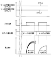
- FIG. 6 is a timing chart showing an example of signals flowing in the LED drive circuit of FIG. 5 related to the first embodiment. 4 is a timing chart illustrating an example in which instability occurs in a current waveform when a plurality of LEDs are caused to emit light by a single LED driver in relation to the first embodiment.
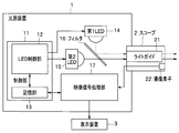
- FIG. 1 is a block diagram showing a configuration of an imaging system.
- the imaging system is a system that illuminates a subject and captures an image.
- the imaging system is a scope 2 as an imaging device, and supplies illumination light to the scope 2 and processes a video signal output from the scope 2.
- a light source device 1 and a display device 3 for displaying a video signal processed by the light source device 1 are provided.
- the scope 2 is configured, for example, as an electronic endoscope.
- the scope 2 transmits the illumination light supplied from the light source device 1 to the distal end side and irradiates the subject, and the subject irradiated with the illumination light.
- an image pickup device 22 such as a CCD or a CMOS that picks up an optical image and generates a video signal.
- the imaging element 22 captures an optical image of a subject illuminated by a first LED 14 (to be described later) of the light source device 1 to generate a first video signal related to the first band light.
- An imaging unit that captures an optical image of a subject illuminated by the 2LED 15 and generates a second video signal related to the second band light.
- the image sensor 22 is configured as, for example, a single-plate color image sensor, and includes an R video signal related to red (R) band light, a G video signal related to green (G) band light, and blue ( B video signal related to the band light of B) can be generated.
- illumination light supplied from the light source device 1 includes purple (V) band light in addition to RGB light (this purple (V) band light is, for example, NBI (registered trademark) (Narrow Band Imaging)).
- this purple (V) band light is, for example, NBI (registered trademark) (Narrow Band Imaging)
- the image sensor 22 uses, for example, a pixel for receiving blue (B) band light to generate a V video signal related to purple (V) band light. To do.
- the light source device 1 includes a control unit 11 having an LED control unit 12 and a storage unit 13, a first LED 14, a second LED 15, a filter 16, and a video signal processing unit 17.
- the control unit 11 includes a CPU, for example, and controls the light source device 1.
- the LED control unit 12 turns on / off the first LED 14 and the second LED 15 by switching the presence / absence of power supply, and further adjusts the power supplied to the first LED 14 and the second LED 15 by current adjustment, PWM adjustment, or a combination thereof.
- the control of the first LED 14 and the second LED 15 by the LED control unit 12 is performed according to an observation mode such as a white light observation mode, an NBI observation mode, and a fluorescence observation mode, for example.
- the storage unit 13 includes a first deterioration rate of the first LED 14 (where the deterioration rate is a deterioration rate with respect to the unit cumulative lighting time), a second deterioration rate of the second LED 15, and an initial state (a new state that is unused). ) And the second initial emitted light amount of the second LED 15 in the initial state. Further, the storage unit 13 receives and stores the first cumulative lighting time of the first LED 14 and the second cumulative lighting time of the second LED 15 from the LED control unit 12.
- the unit 13 includes a first table indicating a correspondence relationship between the first cumulative lighting time and the first emission light amount (this correspondence relationship corresponds to the first deterioration rate described above), a second table And a second table showing a correspondence relationship between the accumulated lighting time and the second emitted light amount (this correspondence relationship corresponds to the above-described second deterioration rate).
- the first LED 14 is turned on by power supply based on the control of the LED control unit 12 to emit first band light, and the amount of emitted light decreases at a first deterioration rate as the first cumulative lighting time increases. 1 light emitting element.
- the second LED 15 is lit by power supply based on the control of the LED control unit 12 to emit second band light, and the amount of emitted light decreases at a second deterioration rate as the second cumulative lighting time increases. 2 light emitting elements.
- the first deterioration rate and the second deterioration rate may be different or the same.
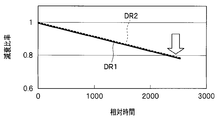
- FIG. 3 is a time chart showing an example of a light emission amount attenuation ratio of each color LED due to a change with time.
- FIG. 3 (and FIG. 4 to be described later), the amount of emitted light with the increase in relative accumulated lighting time when the amount of emitted light of the first LED 14 and the second LED 15 when the accumulated lighting time is 0 is 1.
- the attenuation ratio is shown.
- the attenuation ratio DR2 of the second LED 15 hardly shows a decrease even when the relative cumulative lighting time increases.
- the attenuation ratio DR1 of the first LED 14 decreases at a faster rate than the attenuation ratio DR2 of the second LED 15 as the relative cumulative lighting time increases. Therefore, it can be seen that when the cumulative lighting time of the first LED 14 increases, the emitted light amount decreases at a faster deterioration rate than the second LED 15.
- the first deterioration rate and the second deterioration rate are different from each other as shown in FIG. 3, it is a coincidence that the deterioration rate and the cumulative lighting time coincide with each other (for example, the first deterioration rate is -10 (% / 1000 hours), the second deterioration rate is -5 (% / 1000 hours), but the cumulative lighting time of the first LED 14 is 500 hours, and the cumulative lighting time of the second LED 15 is 1000 hours.
- the first LED 14 and the second LED 15 have a difference in the degree of deterioration except in the case where the degree of deterioration of both coincides with ⁇ 5%.
- the light source device 1 includes an R-LED that emits red light, a G-LED that emits green light, and a B-LED that emits blue light.
- the imaging system includes a white light observation mode performed by turning on the R-LED, the G-LED, and the B-LED, a G-LED as a reference light emission source, and a B-LED as an excitation light emission source.
- a fluorescence observation mode performed by lighting is possible.
- the G-LED and B-LED emit light in both the white light observation mode and the fluorescence observation mode, but the R-LED emits light only in the white light observation mode, and emits light in the fluorescence observation mode.
- the degree of deterioration there is a difference in the cumulative lighting time between the R-LED, the G-LED, and the B-LED, and as a result, there is also a difference in the degree of deterioration.
- the light source device 1 further includes a V-LED that emits purple light in addition to the R-LED, the G-LED, and the B-LED.
- the imaging system is further capable of an NBI observation mode in which the V-LED as the first narrow-band light emitting light source and the G-LED as the second narrow-band light emitting light source are turned on.
- An example of the light emission mode in such a case is that the R-LED emits light only in the white light observation mode, the V-LED emits light only in the NBI observation mode, and the B-LED emits light in the white light observation mode and the fluorescence observation mode.
- the G-LED emits light in the white light observation mode, the fluorescence observation mode, and the NBI observation mode (however, the B-LED and V-LED emit light simultaneously in the white light observation mode) This is just an example. Thus, it is considered that there is a difference in the cumulative lighting time among the R-LED, G-LED, B-LED, and V-LED, that is, there is also a difference in the degree of deterioration.
- the filter 16 is configured, for example, as a beam splitter, reflects the first band light emitted from the first LED 14, guides it to the incident end of the light guide 21, and transmits the second band light emitted from the second LED 15. Thus, the light guide 21 is led to the incident end.
- the video signal processing unit 17 processes the video signal acquired from the image sensor 22 and outputs it to the display device 3.
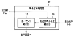
- the video signal processing unit 17 includes a light emitting element deterioration degree correcting unit 18 that is a deterioration degree correcting unit, and a color balance correcting unit 19 provided at a subsequent stage of the light emitting element deterioration degree correcting unit 18. It is equipped with.
- FIG. 2 is a block diagram showing the configuration of the video signal processing unit 17.
- the light emitting element deterioration degree correction unit 18 acquires a first emitted light amount that is the current emitted light amount of the first LED 14 based on the first cumulative lighting time read from the storage unit 13, and reads the first emitted light amount from the storage unit 13. Based on the second accumulated lighting time, a second emitted light amount that is the current emitted light amount of the second LED 15 is acquired.
- the light emitting element deterioration degree correction unit 18 multiplies the first deterioration rate V1 of the first LED 14 by the first cumulative lighting time t1 that is the cumulative lighting time of the first LED 14 at the current time.
- V1 ⁇ t1 the first cumulative lighting time of the first LED 14 at the current time.
- the light emitting element deterioration degree correction unit 18 multiplies the second deterioration rate V2 of the second LED 15 by the second cumulative lighting time t2 that is the cumulative lighting time of the second LED 15 at the present time, thereby reducing the second reduction rate.
- V2 ⁇ t2 is calculated, and a value (1 ⁇ V2 ⁇ t2) obtained by subtracting the second reduction rate from 1 is multiplied by the second initial emission light amount A2 (0), thereby obtaining the second cumulative lighting time t2.
- A2 (t2) (1 ⁇ V2 ⁇ t2) ⁇ A2 (0) Calculate as follows.
- the approximation in which the first deterioration speed V1 of the first LED 14 and the second deterioration speed V2 of the second LED 15 have constant values is performed.
- the first emitted light amount A1 and the second emitted light amount A2 are expressed as follows:
- A1 (t1) A1 (0) exp ⁇ ( ⁇ 1 ⁇ t1) ⁇
- A2 (t2) A2 (0) exp ⁇ -( ⁇ 2 ⁇ t2) ⁇
- ⁇ 1 is a positive deterioration coefficient related to the first LED 14
- ⁇ 2 is a positive deterioration coefficient related to the second LED 15. Note that the change in the degree of deterioration of the light emitting element may be described using a more complicated mathematical expression.
- the light emitting element deterioration degree correction unit 18 refers to the first table described above using the first cumulative lighting time to obtain the first emitted light amount.
- the second emitted light amount is acquired by acquiring and referring to the second table described above using the second cumulative lighting time.
- the light emitting element deterioration degree correcting unit 18 performs gain adjustment using a number obtained by dividing one of the first emitted light amount A1 (t1) and the second emitted light amount A2 (t2) by the other as a gain coefficient, By performing the process on the other of the first video signal and the second video signal, the difference in the deterioration degree between the first LED 14 and the second LED 15 is corrected.
- the light emitting element deterioration degree correction unit 18 uses the number A1 (t1) / A2 (t2) obtained by dividing the first emitted light amount A1 (t1) by the second emitted light amount A2 (t2) as the gain coefficient.
- A1 (t1) / A2 (t2) obtained by dividing the first emitted light amount A1 (t1) by the second emitted light amount A2 (t2) as the gain coefficient.
- Sig2 ′ Sig2 ⁇ A1 (t1) / A2 (t2)
- the corrected second video signal Sig2 ′ is calculated to correct the difference between the deterioration degrees of the first LED 14 and the second LED 15.
- FIG. 4 is a time chart showing an example when the emission amount attenuation ratio due to change with time is substantially the same for each color LED.
- ⁇ A2 (t2) / A1 (t1) The difference between the deterioration degrees of the first LED 14 and the second LED 15 may be corrected by calculating the corrected first video signal Sig1 ′ as described above.
- the reference video signal and thus the reference light-emitting element
- the light emitting element having a higher degree of deterioration (for example, the first LED 14) is supplied with a large amount of power to compensate for the degree of deterioration and emits light with the same amount of light emission as in the initial state. It is difficult to make it. Therefore, there is no choice but to reduce the light emission amount of the light emitting element with the smaller deterioration degree by matching the light emitting element with the smaller deterioration degree with the light emitting element with the larger deterioration degree.
- the deterioration degree correction in the present embodiment is multiplication of the video signal by the gain coefficient by the video signal processing unit 17, the video signal obtained by causing the light emitting element having the higher deterioration degree to emit light is used. It is possible to increase the gain according to the video signal obtained by emitting light from the light emitting element with the lower degradation level, and obtain a signal with the same brightness as when light was emitted in the initial state. There is an advantage that can be.
- the color balance correction unit 19 performs color balance adjustment on the first video signal and the second video signal that have been corrected by the light emitting element deterioration degree correction unit 18. That is, the first video signal and the second video signal whose color balance is adjusted by the color balance correction unit 19 are video signals in which the difference in deterioration level is corrected by the light emitting element deterioration level correction unit 18, so that the deterioration occurs. It is possible to perform a normal color balance adjustment similar to the color balance adjustment for a video signal in which the degree difference does not occur.
- the color balance correction unit 19 since the processing of the light emitting element deterioration degree correction unit 18 is performed in the previous stage of the color balance correction unit 19, the color balance correction unit 19 does not need to have a special configuration different from the conventional one, and the same color as in the initial state. There is an advantage that the same processing can be performed as when processing an image obtained by imaging a subject illuminated by balanced illumination light.
- the emitted light amounts of a plurality of light emitting elements having different bands are acquired based on the cumulative lighting time of each light emitting element, and the gain adjustment based on the ratio of the emitted light amounts is performed on the video signal. For this reason, it is possible to suppress the change in the color balance of the illumination light with time by correcting the difference in the degree of deterioration of the plurality of light emitting elements at a low cost.
- the storage capacity of the storage unit 13 there is an advantage that the processing load is light and the processing load is light.
- the correspondence between the cumulative lighting time and the amount of emitted light is stored as a table, it is a table reference even if the relationship between the cumulative lighting time and the amount of emitted light is complicated if described in a function. If there is information on the cumulative lighting time, the current amount of emitted light can be easily obtained.
- the color balance correction unit 19 Since the color balance correction unit 19 performs the color balance adjustment on the video signal corrected by the light emitting element deterioration degree correction unit 18, the color balance correction unit 19 considers the deterioration degree of the light emitting element. Therefore, it is possible to perform the same color balance adjustment as before.
- FIG. 5 is a diagram showing the configuration of the LED drive circuit
- FIG. 6 is a timing chart showing an example of a signal flowing through the LED drive circuit of FIG. 5
- FIG. 7 is a diagram when a plurality of LEDs are caused to emit light by one LED driver. It is a timing chart which shows the example which instability arises in a current waveform.
- the LED driver that drives the first LED 14 and the LED driver that drives the second LED 15 are combined into one LED driver (light emitting element driving circuit) in order to reduce the price. May be used in combination.
- FIG. 5 shows an example of such a configuration.
- the LED control unit 12 uses a single LED driver 42 to drive the first LED 14 (eg, V-LED (purple LED)) and the second LED 15 (eg, W-LED (white LED)). It has become.
- the first LED 14 eg, V-LED (purple LED)
- the second LED 15 eg, W-LED (white LED)
- the LED control unit 12 is connected to a DAC (digital / analog converter) 41 and an LED driver 42, and outputs a digital signal to the LED driver 42 and outputs an analog signal to the LED driver 42 via the DAC 41. It is supposed to be.
- DAC digital / analog converter
- the LED driver 42 is further connected to the switching smoothing unit 43, and is also connected to the switch 44 via the PWMGH terminal and the switch 45 via the PWMGL terminal.
- the switching smoothing unit 43 is connected to the ground via the first LED 14, the switch 44, and the resistor 46, and is further connected to the ground via the second LED 15, the switch 45, and the resistor 47.
- the first LED 14 and the second LED 15 are connected to the switching smoothing unit 43 through a common anode (COMMON ANODE).
- the LED control unit 12 outputs a digital signal indicating the current setting value for W-LED and a digital signal indicating the current setting value for V-LED to the DAC 41.
- the DAC 41 converts the digital signal into an analog signal, and sends the analog value signal for W-LED (current setting value CTRL_L) to the CTRL_L input terminal of the LED driver 42 and the analog value signal for V-LED (current setting).
- Value CTRL_H) is output to the CTRL_H input terminal of the LED driver 42 (see also FIGS. 6 and 7).
- a lighting LED selection signal is input to the CTRL_SEL terminal of the LED driver 42 from the LED_SEL terminal of the LED control unit 12.
- This lighting LED selection signal becomes a signal for selecting the current setting value CTRL_L to turn on the switch 45 and turning off the switch 44 in the lighting period in which the lighting is sequentially changed, for example.
- the current set value CTRL_H is selected to turn on the switch 44 and turn off the switch 45 (see also FIGS. 6 and 7).
- a pulse signal PWM which is a pulse width modulation signal, is input from the PWM terminal of the LED control unit 12 to the PWM terminal of the LED driver 42 (see also FIGS. 6 and 7).
- the LED driver 42 sets a current value for the W-LED and outputs a pulse width modulated drive pulse to the switching smoothing unit 43.
- the switching smoothing unit 43 smoothes the drive pulse input from the LED driver 42 using a capacitor or the like. As a result, the smoothed current for the W-LED is applied to the second LED 15 which is the W-LED (see also FIGS. 6 and 7).
- the LED driver 42 sets a current value for the V-LED and outputs a pulse width modulated drive pulse to the switching smoothing unit 43.
- the switching smoothing unit 43 smoothes the drive pulse input from the LED driver 42 as described above. As a result, the smoothed current for the V-LED is applied to the first LED 14 which is a V-LED (see also FIGS. 6 and 7).
- the LED control unit 12 does not temporally change the digital signal indicating the current setting value for V-LED and the digital signal indicating the current setting value for W-LED. Each constant value was output to the DAC 41.
- the LED control unit 12 makes the digital signal indicating the current setting value for V-LED the same as the digital signal indicating the current setting value for W-LED.
- the W-LED lighting period and the V-LED lighting period are output to the DAC 41 while being changed with time so as to have different set values.
- the LED control unit 12 outputs a digital signal to the DAC 41 so that the same value as CTRL_L shown in FIG. 7 becomes the value of CTRL_L and CTRL_H in FIG.
- a digital signal is output to the DAC 41 so that the same value as CTRL_H shown in FIG. 7 becomes the value of CTRL_L and CTRL_H in FIG.
- the current setting value CTRL_L and the current setting value CTRL_H input to the LED driver 42 change with time, but are the same value when viewed at the same time point. Therefore, there is no difference between the current setting value CTRL_L and the current setting value CTRL_H at any time, and the current waveforms applied to the first LED 14 and the second LED 15 can be stabilized.
- two light-emitting elements are driven by one light-emitting element driving circuit.
- the above-described technique can be similarly applied to driving three or more light-emitting elements by one light-emitting element driving circuit. it can.
- the current waveform output to any light emitting element can be stabilized.
- the light emission luminance of each light emitting element can be stabilized.
- the color balance of the video signal can be kept constant, and the quality of the video can be improved.
- the present invention is not limited to the above-described embodiment as it is, and can be embodied by modifying the constituent elements without departing from the scope of the invention in the implementation stage.
- various aspects of the invention can be formed by appropriately combining a plurality of components disclosed in the embodiment. For example, you may delete some components from all the components shown by embodiment.
- the constituent elements over different embodiments may be appropriately combined.
Landscapes
- Health & Medical Sciences (AREA)
- Life Sciences & Earth Sciences (AREA)
- Surgery (AREA)
- Physics & Mathematics (AREA)
- Engineering & Computer Science (AREA)
- Optics & Photonics (AREA)
- Pathology (AREA)
- Medical Informatics (AREA)
- Nuclear Medicine, Radiotherapy & Molecular Imaging (AREA)
- Heart & Thoracic Surgery (AREA)
- Biomedical Technology (AREA)
- Radiology & Medical Imaging (AREA)
- Veterinary Medicine (AREA)
- Public Health (AREA)
- General Health & Medical Sciences (AREA)
- Biophysics (AREA)
- Molecular Biology (AREA)
- Animal Behavior & Ethology (AREA)
- Signal Processing (AREA)
- Multimedia (AREA)
- General Physics & Mathematics (AREA)
- Astronomy & Astrophysics (AREA)
- Microelectronics & Electronic Packaging (AREA)
- Endoscopes (AREA)
- Studio Devices (AREA)
Priority Applications (4)
| Application Number | Priority Date | Filing Date | Title |
|---|---|---|---|
| JP2015550513A JP5974187B2 (ja) | 2014-05-14 | 2015-03-26 | 撮像システム |
| EP15792206.3A EP3146889A4 (de) | 2014-05-14 | 2015-03-26 | Bildaufnahmesystem |
| CN201580018784.3A CN106163374B (zh) | 2014-05-14 | 2015-03-26 | 摄像系统 |
| US15/285,621 US20170020378A1 (en) | 2014-05-14 | 2016-10-05 | Image pickup system |
Applications Claiming Priority (2)
| Application Number | Priority Date | Filing Date | Title |
|---|---|---|---|
| JP2014100797 | 2014-05-14 | ||
| JP2014-100797 | 2014-05-14 |
Related Child Applications (1)
| Application Number | Title | Priority Date | Filing Date |
|---|---|---|---|
| US15/285,621 Continuation US20170020378A1 (en) | 2014-05-14 | 2016-10-05 | Image pickup system |
Publications (1)
| Publication Number | Publication Date |
|---|---|
| WO2015174146A1 true WO2015174146A1 (ja) | 2015-11-19 |
Family
ID=54479691
Family Applications (1)
| Application Number | Title | Priority Date | Filing Date |
|---|---|---|---|
| PCT/JP2015/059479 Ceased WO2015174146A1 (ja) | 2014-05-14 | 2015-03-26 | 撮像システム |
Country Status (5)
| Country | Link |
|---|---|
| US (1) | US20170020378A1 (de) |
| EP (1) | EP3146889A4 (de) |
| JP (1) | JP5974187B2 (de) |
| CN (1) | CN106163374B (de) |
| WO (1) | WO2015174146A1 (de) |
Cited By (1)
| Publication number | Priority date | Publication date | Assignee | Title |
|---|---|---|---|---|
| CN111466859A (zh) * | 2019-01-24 | 2020-07-31 | 富士胶片株式会社 | 内窥镜系统 |
Families Citing this family (4)
| Publication number | Priority date | Publication date | Assignee | Title |
|---|---|---|---|---|
| WO2017175314A1 (ja) * | 2016-04-05 | 2017-10-12 | オリンパス株式会社 | 湾曲情報導出装置及び内視鏡システム |
| JP7081501B2 (ja) * | 2017-01-06 | 2022-06-07 | ソニーグループ株式会社 | 制御装置、制御システム、および制御方法 |
| JP6740481B2 (ja) * | 2017-08-22 | 2020-08-12 | 富士フイルム株式会社 | 光源装置、内視鏡システム、及び光源装置の作動方法 |
| JP2019115017A (ja) * | 2017-12-26 | 2019-07-11 | オムロン株式会社 | アナログ信号入出力装置およびアナログ信号入出力装置の制御方法 |
Citations (5)
| Publication number | Priority date | Publication date | Assignee | Title |
|---|---|---|---|---|
| JP2008243584A (ja) * | 2007-03-27 | 2008-10-09 | Matsushita Electric Works Ltd | 照明装置 |
| JP2009201940A (ja) * | 2008-02-29 | 2009-09-10 | Hoya Corp | 内視鏡光源システム、内視鏡光源装置、内視鏡プロセッサ、および内視鏡ユニット |
| WO2010041494A1 (ja) * | 2008-10-06 | 2010-04-15 | シャープ株式会社 | 照明装置およびそれを備えた液晶表示装置 |
| JP2011233263A (ja) * | 2010-04-23 | 2011-11-17 | Panasonic Electric Works Co Ltd | 照明装置 |
| WO2012161028A1 (ja) * | 2011-05-26 | 2012-11-29 | オリンパスメディカルシステムズ株式会社 | 光源装置 |
Family Cites Families (5)
| Publication number | Priority date | Publication date | Assignee | Title |
|---|---|---|---|---|
| JP2004141377A (ja) * | 2002-10-24 | 2004-05-20 | Pentax Corp | ゆらぎ補償装置及び電子内視鏡用画像信号処理装置 |
| KR101487548B1 (ko) * | 2007-05-18 | 2015-01-29 | 소니 주식회사 | 표시 장치, 표시 장치의 제어 방법 및 컴퓨터 프로그램이 기록된 기록 매체 |
| CN103607940B (zh) * | 2011-06-21 | 2015-11-25 | 奥林巴斯株式会社 | 荧光观察装置、荧光观察系统和荧光图像处理方法 |
| JP5526300B1 (ja) * | 2012-10-09 | 2014-06-18 | オリンパスメディカルシステムズ株式会社 | 内視鏡装置及び内視鏡の偏光素子の劣化検出方法 |
| JP6013382B2 (ja) * | 2014-02-27 | 2016-10-25 | 富士フイルム株式会社 | 内視鏡システム及びその作動方法 |
-
2015
- 2015-03-26 JP JP2015550513A patent/JP5974187B2/ja active Active
- 2015-03-26 WO PCT/JP2015/059479 patent/WO2015174146A1/ja not_active Ceased
- 2015-03-26 CN CN201580018784.3A patent/CN106163374B/zh active Active
- 2015-03-26 EP EP15792206.3A patent/EP3146889A4/de not_active Withdrawn
-
2016
- 2016-10-05 US US15/285,621 patent/US20170020378A1/en not_active Abandoned
Patent Citations (5)
| Publication number | Priority date | Publication date | Assignee | Title |
|---|---|---|---|---|
| JP2008243584A (ja) * | 2007-03-27 | 2008-10-09 | Matsushita Electric Works Ltd | 照明装置 |
| JP2009201940A (ja) * | 2008-02-29 | 2009-09-10 | Hoya Corp | 内視鏡光源システム、内視鏡光源装置、内視鏡プロセッサ、および内視鏡ユニット |
| WO2010041494A1 (ja) * | 2008-10-06 | 2010-04-15 | シャープ株式会社 | 照明装置およびそれを備えた液晶表示装置 |
| JP2011233263A (ja) * | 2010-04-23 | 2011-11-17 | Panasonic Electric Works Co Ltd | 照明装置 |
| WO2012161028A1 (ja) * | 2011-05-26 | 2012-11-29 | オリンパスメディカルシステムズ株式会社 | 光源装置 |
Non-Patent Citations (1)
| Title |
|---|
| See also references of EP3146889A4 * |
Cited By (5)
| Publication number | Priority date | Publication date | Assignee | Title |
|---|---|---|---|---|
| CN111466859A (zh) * | 2019-01-24 | 2020-07-31 | 富士胶片株式会社 | 内窥镜系统 |
| JP2020116148A (ja) * | 2019-01-24 | 2020-08-06 | 富士フイルム株式会社 | 内視鏡システム |
| US11344191B2 (en) | 2019-01-24 | 2022-05-31 | Fujifilm Corporation | Endoscope system including processor for determining type of endoscope |
| JP7184657B2 (ja) | 2019-01-24 | 2022-12-06 | 富士フイルム株式会社 | 内視鏡システム |
| CN111466859B (zh) * | 2019-01-24 | 2024-02-02 | 富士胶片株式会社 | 内窥镜系统 |
Also Published As
| Publication number | Publication date |
|---|---|
| CN106163374B (zh) | 2018-02-23 |
| JP5974187B2 (ja) | 2016-08-23 |
| US20170020378A1 (en) | 2017-01-26 |
| JPWO2015174146A1 (ja) | 2017-04-20 |
| EP3146889A1 (de) | 2017-03-29 |
| CN106163374A (zh) | 2016-11-23 |
| EP3146889A4 (de) | 2018-01-10 |
Similar Documents
| Publication | Publication Date | Title |
|---|---|---|
| JP6138203B2 (ja) | 内視鏡装置 | |
| CN105407789B (zh) | 内窥镜系统、内窥镜系统的工作方法 | |
| JP5974187B2 (ja) | 撮像システム | |
| JP6010255B2 (ja) | 光源装置及び光源装置の作動方法 | |
| US8659242B2 (en) | Light source apparatus | |
| US10610082B2 (en) | Endoscope apparatus | |
| US10531008B2 (en) | Image pickup system | |
| JP2010158415A (ja) | 内視鏡用光源装置 | |
| EP2859836A1 (de) | Endoskopvorrichtung | |
| US11744436B2 (en) | Subject observation system, light source apparatus for endoscope, method of operating subject observation system, and recording medium | |
| CN109715042B (zh) | 光源装置 | |
| JP2010158413A (ja) | 内視鏡用光源装置 | |
| JP2012223376A (ja) | 照明用発光ダイオードの制御回路、制御方法及びそれを用いた電子内視鏡装置 | |
| JP6564538B1 (ja) | 内視鏡用光源装置 | |
| WO2019167315A1 (ja) | 内視鏡用光源装置 | |
| JP4715244B2 (ja) | 投写装置 |
Legal Events
| Date | Code | Title | Description |
|---|---|---|---|
| ENP | Entry into the national phase |
Ref document number: 2015550513 Country of ref document: JP Kind code of ref document: A |
|
| 121 | Ep: the epo has been informed by wipo that ep was designated in this application |
Ref document number: 15792206 Country of ref document: EP Kind code of ref document: A1 |
|
| REEP | Request for entry into the european phase |
Ref document number: 2015792206 Country of ref document: EP |
|
| WWE | Wipo information: entry into national phase |
Ref document number: 2015792206 Country of ref document: EP |
|
| NENP | Non-entry into the national phase |
Ref country code: DE |