WO2015174257A1 - Dispositif de traitement d'image, procédé de traitement d'image, dispositif d'imagerie, instrument électronique, et programme - Google Patents
Dispositif de traitement d'image, procédé de traitement d'image, dispositif d'imagerie, instrument électronique, et programme Download PDFInfo
- Publication number
- WO2015174257A1 WO2015174257A1 PCT/JP2015/062635 JP2015062635W WO2015174257A1 WO 2015174257 A1 WO2015174257 A1 WO 2015174257A1 JP 2015062635 W JP2015062635 W JP 2015062635W WO 2015174257 A1 WO2015174257 A1 WO 2015174257A1
- Authority
- WO
- WIPO (PCT)
- Prior art keywords
- image
- filter
- image height
- correction
- pixel
- Prior art date
- Legal status (The legal status is an assumption and is not a legal conclusion. Google has not performed a legal analysis and makes no representation as to the accuracy of the status listed.)
- Ceased
Links
Images






Classifications
-
- G—PHYSICS
- G06—COMPUTING OR CALCULATING; COUNTING
- G06T—IMAGE DATA PROCESSING OR GENERATION, IN GENERAL
- G06T5/00—Image enhancement or restoration
- G06T5/20—Image enhancement or restoration using local operators
-
- H—ELECTRICITY
- H04—ELECTRIC COMMUNICATION TECHNIQUE
- H04N—PICTORIAL COMMUNICATION, e.g. TELEVISION
- H04N1/00—Scanning, transmission or reproduction of documents or the like, e.g. facsimile transmission; Details thereof
- H04N1/40—Picture signal circuits
-
- H—ELECTRICITY
- H04—ELECTRIC COMMUNICATION TECHNIQUE
- H04N—PICTORIAL COMMUNICATION, e.g. TELEVISION
- H04N23/00—Cameras or camera modules comprising electronic image sensors; Control thereof
- H04N23/60—Control of cameras or camera modules
-
- H—ELECTRICITY
- H04—ELECTRIC COMMUNICATION TECHNIQUE
- H04N—PICTORIAL COMMUNICATION, e.g. TELEVISION
- H04N25/00—Circuitry of solid-state image sensors [SSIS]; Control thereof
- H04N25/60—Noise processing, e.g. detecting, correcting, reducing or removing noise
- H04N25/61—Noise processing, e.g. detecting, correcting, reducing or removing noise the noise originating only from the lens unit, e.g. flare, shading, vignetting or "cos4"
- H04N25/615—Noise processing, e.g. detecting, correcting, reducing or removing noise the noise originating only from the lens unit, e.g. flare, shading, vignetting or "cos4" involving a transfer function modelling the optical system, e.g. optical transfer function [OTF], phase transfer function [PhTF] or modulation transfer function [MTF]
-
- H—ELECTRICITY
- H04—ELECTRIC COMMUNICATION TECHNIQUE
- H04N—PICTORIAL COMMUNICATION, e.g. TELEVISION
- H04N25/00—Circuitry of solid-state image sensors [SSIS]; Control thereof
- H04N25/10—Circuitry of solid-state image sensors [SSIS]; Control thereof for transforming different wavelengths into image signals
- H04N25/11—Arrangement of colour filter arrays [CFA]; Filter mosaics
- H04N25/13—Arrangement of colour filter arrays [CFA]; Filter mosaics characterised by the spectral characteristics of the filter elements
- H04N25/134—Arrangement of colour filter arrays [CFA]; Filter mosaics characterised by the spectral characteristics of the filter elements based on three different wavelength filter elements
Definitions
- the present technology relates to an image processing device, an image processing method, an imaging device, an electronic device, and a program.
- the present invention relates to an image processing apparatus, an image processing method, an imaging apparatus, an electronic apparatus, and a program that perform image blur correction.
- Patent Documents 1 to 3 are disclosed as conventional techniques disclosed for correction processing of image noise and blur based on various factors.
- Patent Document 1 discloses a correction processing configuration using different sharpening parameters for each region of a captured image. Specifically, the image correction is performed by increasing the sharpening parameter as the image height (distance from the optical center) increases.
- Patent Document 1 merely performs a process of increasing the intensity of the high-frequency component in accordance with the image height, and does not take into account, for example, a change in the frequency characteristic of blur, and appropriate correction is not performed. there is a possibility.
- Patent Document 2 discloses a configuration in which a blur correction process is performed by selecting a filter corresponding to each lens characteristic in order to cope with blurring that varies depending on lens differences or manufacturing errors.
- this correction processing is applied to blur in which the blur method changes continuously according to the image height, such as the above-described image height-dependent blur, the number of types of filters for blur correction is enormous. could be a number.
- Patent Document 3 applies an appropriate correction according to the image height by applying a filter in which the position of the center of gravity is shifted for each image height with respect to so-called one-sided blur indicating how the blur occurs depending on the image height.
- a configuration to execute is disclosed. More specifically, correction corresponding to blurring is performed by correcting the position of the center of gravity of the filter.
- the focus is on the correction of the center of gravity, the control of the correction strength is not shown, and individual processing corresponding to the strong or weak part is not executed, and appropriate correction is not made Will occur.
- JP 2006-246080 A JP 2009-159603 A JP 2010-081263 A
- the present technology has been made in view of such a situation, and makes it possible to perform an appropriate correction according to the image height.
- An image processing apparatus is an object to be corrected using an acquisition unit that acquires a filter that performs blur correction that is set for each of a plurality of image heights, and the filter acquired by the acquisition unit.
- a correction unit that corrects the pixel value of the pixel at the obtained image height.
- the correction unit applies the filter that is set to an image height adjacent to the image height that is the correction target to a pixel value of the pixel that is the correction target, and the image height that is the correction target.
- a coefficient can be calculated from the positional relationship with the adjacent image height, and a corrected pixel value can be calculated using the pixel value after applying the filter and the coefficient.
- the correction unit calculates a coefficient from a positional relationship between the image height that is the correction target and the adjacent image height, and the filter that is set to an image height adjacent to the image height that is the correction target; A filter to be applied to the pixel value of the pixel to be corrected is generated using the coefficient, and a corrected pixel value is calculated using the generated filter and the pixel value of the pixel to be corrected To be able to.
- PSF Point Spread Function
- the calculation of the coefficient of the filter can use a Wiener filter.
- the image height for which the filter is set can be the image height at which the shape of the PSF changes greatly.
- MTF Modulation Transfer Function
- the calculation of the coefficient of the filter can use a Wiener filter.
- the image height for which the filter is set can be an inflection point of the MTF data.
- An image processing method acquires a filter that performs blur correction that is set for each of a plurality of image heights, and uses the acquired filter to obtain a pixel of a pixel at an image height that is a correction target. A step of correcting the value.
- a program acquires a filter that performs blur correction that is set for each of a plurality of image heights, and uses the acquired filter to calculate a pixel value of a pixel at an image height that is a correction target.
- a process including a correction step is executed.
- An imaging apparatus uses the imaging device, an acquisition unit that acquires a filter that performs blur correction that is set for each of a plurality of image heights, and the filter acquired by the acquisition unit, A correction unit that corrects a pixel value of a pixel at an image height that is a correction target among pixels picked up by the image pickup device;
- An electronic apparatus is subjected to correction using an acquisition unit that acquires a filter that performs blur correction that is set for each of a plurality of image heights, and the filter acquired by the acquisition unit.
- a correction unit that corrects a pixel value of a pixel at an image height and an image processing unit that performs predetermined image processing on the pixel value after correction from the correction unit.
- a filter that performs blur correction that is set for each of a plurality of image heights is acquired, and the acquired filter is used to correct the correction target.
- the pixel value of the pixel at the set image height is corrected.
- the imaging device includes the image processing device, and includes an imaging element for capturing an image.
- An electronic apparatus includes the image processing device, and includes a processing unit that further processes a signal processed by the image processing device.
- blurring occurs according to lens characteristics and characteristics of an imaging element such as a CCD or CMOS.
- image blur due to lens aberration increases as the image height (distance from the optical center) increases.
- the center region of the image has a small blur. That is, the closer to the optical center (the smaller the image height), the smaller the blur. On the other hand, the greater the distance from the optical center, that is, the greater the image height, the greater the blur.
- the blur generated in the image taken by the camera tends to be smaller at the center of the image region near the optical center of the camera lens and larger at the peripheral region of the image far from the optical center of the lens.
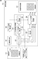
- FIG. 1 is a diagram illustrating a configuration of an embodiment of an imaging apparatus to which the present technology is applied.
- the imaging apparatus 100 includes an optical lens 111, an imaging element (image sensor) 112, a signal processing unit 113, a control unit 114, and a memory 115.
- the imaging device is an aspect of an image processing device.
- the image processing apparatus of the present disclosure includes an apparatus such as a personal computer (PC).
- An image processing apparatus such as a PC does not include the optical lens 111 and the image sensor 112 of the image capturing apparatus 100 illustrated in FIG. 1, and includes other components, and includes an acquisition data input unit or a storage unit of the image capturing apparatus 100. It becomes composition.
- the imaging apparatus 100 illustrated in FIG. 1 will be described as a representative example of the image processing apparatus of the present disclosure.
- the imaging apparatus 100 illustrated in FIG. 1 is, for example, a still camera or a video camera.
- the image pickup device 112 of the image pickup apparatus 100 shown in FIG. 1 has a configuration including a color filter having a Bayer array composed of RGB arrays.
- the configuration and processing using the image sensor 112 having the RGB array will be described, but the present technology can also be applied to a configuration using an image sensor having, for example, an RGBW array other than the RGB array.
- the present invention can be applied to a configuration using an image sensor having an arrangement such as Y (yellow), C (cyan), and M (magenta).
- the present technology can be applied to color arrangements other than the arrangements exemplified here.
- the imaging device 112 of the imaging apparatus 100 shown in FIG. That is, Red (R) that transmits wavelengths near red, Green (G) that transmits wavelengths in the vicinity of green, Blue (B) that transmits wavelengths near blue, It is an image sensor provided with a filter having these three types of spectral characteristics.
- the image sensor 112 having the RGB array 121 receives any of RGB light in units of pixels via the optical lens 111, and generates and outputs an electrical signal corresponding to the received light signal intensity by photoelectric conversion.
- a mosaic image composed of three types of RGB spectra is obtained by the image sensor 112.
- the output signal of the image sensor 112 is input to the image signal correction unit 131 of the signal processing unit 113.
- the image signal correction unit 131 executes a blur correction process in consideration of, for example, a blur method that changes according to an image height (distance from the optical center) and a focus position.
- a blur correction process in consideration of, for example, a blur method that changes according to an image height (distance from the optical center) and a focus position.
- the configuration of the image signal correction unit 131 will be described later with reference to FIG.
- the mosaic image subjected to the blur correction in the image signal correction unit 131 is output to the RGB signal processing unit 132.
- the output of the image signal correction unit 131 is data having a Bayer array, similar to the output from the image sensor 112.
- the RGB signal processing unit 132 generates a color image 116 by performing demosaic processing, white balance adjustment processing, ⁇ correction processing, and the like.
- the generated color image 116 is recorded in the memory 115.
- the control unit 114 controls these series of processes.
- a program for executing a series of processes is stored in the memory 115, and the control unit 114 executes the program read from the memory 115 and controls the series of processes.
- the memory 115 can be configured by various recording media such as a magnetic disk, an optical disk, and a flash memory.
- the image signal correction unit 131 includes an image height calculation unit 201, a blend coefficient calculation unit 202, a line memory 203, a lens aberration correction processing unit 204, an edge detection unit 205, and an edge / flat portion blend processing unit. 206.
- the lens aberration correction processing unit 204 includes a lens aberration correction unit 221 and a blend processing unit 222.
- the pixel value signal corresponding to each pixel output from the image sensor 112 is temporarily stored in the line memory 203.
- An xy address indicating the coordinate position of each pixel associated with the pixel value of each pixel is output to the image height calculation unit 201.
- the line memory 203 includes a line memory for the horizontal 7 lines of the image sensor 112, for example. From the line memory 203, data for seven horizontal lines are sequentially output in parallel.
- the output destinations are the lens aberration correction unit 221, the edge detection unit 205, and the edge / flat portion blend processing unit 206.
- the imaging data of the RGB array 121 is output in units of 7 lines to each of these processing units.
- the edge detection unit 205 verifies the output signal from the line memory 203, generates edge information included in the image, for example, edge information including the edge direction and the edge strength, and outputs the edge information to the edge / flat part blend processing unit 206. . Specifically, for example, the edge / flat part blend processing unit 206 calculates the flatness (weightFlat) calculated from the pixel information of 7 ⁇ 7 pixels with the processing target pixel (the center pixel of 7 ⁇ 7 pixels) as the center. Output to.
- the flatness (weightFlat) calculation process can be executed as a process similar to the process described in Japanese Patent Application Laid-Open No. 2011-55038, which is an earlier application of the present applicant.
- the lens aberration correction processing unit 204 verifies the input signal (Rin, Gin, Bin) from the line memory 203, performs a process for correcting image blur, and obtains a blur correction signal (Rd, Gd, Bd) is calculated and output to the edge / flat portion blend processing unit 206.
- the lens aberration correction processing unit 204 corrects image blur, particularly image blur depending on the image height in the present embodiment.
- the lens aberration correction unit 221 of the lens aberration correction processing unit 204 acquires lens aberration correction filter coefficients at each image height.
- the lens aberration correction filter coefficient is a coefficient calculated using, for example, a Wiener filter in order to correct lens aberrations that differ for each image height, as will be described later.
- the correction result by the lens aberration correction unit 221 is supplied to the blend processing unit 222.
- the coefficient ⁇ from the blend coefficient calculating unit 202 is also supplied to the blend processing unit 222.
- the blend processing unit 222 Based on the coefficient ⁇ from the blend coefficient calculation unit 202, the blend processing unit 222 generates a blur correction signal (Rd, Gd, Bd) after lens aberration correction at an image height for which no lens aberration correction filter coefficient is set, This is supplied to the edge / flat portion blend processing unit 206.
- the edge / flat portion blend processing unit 206 is output from the RGB signal (Rin, Gin, Bin) in the output signal from the line memory 203, the edge information output from the edge detection unit 205, and the lens aberration correction processing unit 204.
- a blur correction signal (Rd, Gd, Bd) is input.
- the edge / flat part blend processing unit 206 uses these pieces of information to generate an output signal RGB that has been subjected to blur correction in consideration of edges, and outputs the output signal RGB to the RGB signal processing unit 132.
- the edge / flat part blend processing unit 206 is based on the edge information of the processing target pixel calculated by the edge detection unit 205, that is, the pixel information of 7 ⁇ 7 pixels centering on the processing target pixel (center pixel of 7 ⁇ 7 pixels).
- the weighted average processing of the blur correction signal (Rd, Gd, Bd) output from the lens aberration correction processing unit 204 is executed, and the RGB pixel values of the RGB array 121 are obtained. calculate.
- RGB pixel values are determined according to the following formula.
- R, G, B obtained as a calculation result of this equation are output to the RGB signal processing unit 132.
- the RGB signal processing unit 132 performs signal processing on the RGB array (Bayer array) signal output from the edge / flat part blend processing unit 206 as signal processing on the RGB array (Bayer array) signal, and performs the color image 116 (FIG. 1) is generated.
- the RGB signal processing unit 132 generates, for example, a color image 116 by executing white balance adjustment processing, demosaic processing, shading processing, RGB color matrix processing, ⁇ correction processing, and the like.
- the lens aberration correction filter coefficient is calculated using, for example, a Wiener filter.
- the winner filter will be briefly described.
- Ideal image original image
- Blurred shot image (3) a restored image restored by filter application processing on the captured image; Assume these three images.
- f (x, y) is an ideal image (original image) without blur
- g (x, y) is a captured image including blur
- h (x, y) is a degradation function due to lens aberration or camera shake
- n (x, y) is a noise component
- X, y is the pixel position of each image
- f (x, y) to n (x, y) may indicate the pixel value of the coordinate position (x, y) of each image.
- Equation (2) G (u, v), H (u, v), F (u, v), and N (u, v) are g (x, y), h (x, y), and f, respectively.
- the image obtained by performing inverse Fourier transform of this filter k (x, y) and the image f ′ (x, y) corrected for blur are obtained by convolving the observed image in real space. Can do.
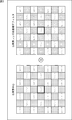
- FIG. An example of the blur correction process by the Wiener filter according to the above equation (5) is shown in FIG.
- FIG. A) Captured image G
- B Wiener filter K Is shown.
- the photographed image is a RAW image composed of RGB pixels.
- the correction target pixel is the center G pixel of 7 ⁇ 7 pixels shown on the left side of FIG.
- the Wiener filter K shown on the right side of FIG. 3 shows a multiplication coefficient for each of a plurality of G pixels included in 7 ⁇ 7 pixels.
- a convolution operation is performed in which the pixel values of the G pixels included in the 7 ⁇ 7 pixels are multiplied by each coefficient and added to calculate a correction pixel value of the central G pixel.
- FIG. 4 shows an example of an image and a filter when processing R pixels.
- the correction target pixel is an R pixel at the center of 7 ⁇ 7 pixels shown on the left side of FIG.
- the Wiener filter K shown on the right side of FIG. 4 shows a multiplication coefficient for each of a plurality of R pixels included in a 7 ⁇ 7 pixel.
- a convolution operation for multiplying and adding each pixel value to the pixel value of the R pixel included in the 7 ⁇ 7 pixel is executed to calculate a correction pixel value of the center R pixel.
- FIG. 5 shows an example of an image and a filter when processing R pixels.
- the correction target pixel is the B pixel at the center of the 7 ⁇ 7 pixels shown on the left side of FIG.
- the Wiener filter K shown on the right side of FIG. 5 shows a multiplication coefficient for each of a plurality of B pixels included in a 7 ⁇ 7 pixel.
- a convolution operation for multiplying and adding each pixel value to the pixel value of the B pixel included in the 7 ⁇ 7 pixel is executed to calculate a correction pixel value of the central B pixel.
- lens PSF Point Spread Function
- PSF point spread function
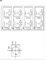
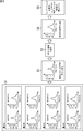
- FIG. 6 shows an example of lens PSF data.
- the diagram shown on the left side of FIG. 6 is a diagram showing the position of the image point, and the graph on the right side shows the PSF data value obtained from each image point.
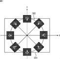
- FIG. 6 shows one image height 302 existing in the effective area 301 of the image sensor (image sensor 112 (FIG. 2)).
- the horizontal direction is the X axis and the vertical direction is the Y axis.
- Intersections between the image height 302 and the Y axis are image points A and C, and intersections between the image height 302 and the X axis are image points B and D.
- the graphs obtained from the image points A to D are shown on the right side of FIG. In addition, the graphs obtained in the sagittal direction and the tangential direction are shown for the image points A to D, respectively.
- the lens PSF has anisotropy and, for example, the degree of blur is different between the sagittal direction and the tangential direction.
- the degree of blur is different even within the same lens.
- Factors that vary the degree of blur include, for example, variations in manufacturing. Therefore, even if the lenses are manufactured in the same process, the degree of blur may be different.
- the lens aberration correction filter coefficients are held for each angle, such as sagittal direction and tangential direction, for each image height, the number of lens aberration correction filter coefficients to be held increases. There is a high possibility that the capacity of the memory for holding it will increase.
- step S1 lens PSF data is acquired at a predetermined image point.
- image points A, image points B, C, and D on the X-axis and Y-axis on the image height 302 of the lens The description will be continued assuming that PSF data in the sagittal direction and the tangential direction are acquired.
- the lens aberration correction filter coefficient at this image height is obtained from four image points located on the same image height at the end of the optical lens 111 .
- step S1 of FIG. 8 here, eight PSF data are acquired. Note that how to determine the image point (image height) for acquiring the PSF data will be described later.
- step S2 averaging is performed using all of the obtained PSF data. In this case, an average of 8 pieces of PSF data is obtained.
- step S3 approximation is performed using the averaged PSF data and one type of Gaussian function.
- the approximation coefficient of the Gaussian function is obtained by solving the least square method of the PSF data that has been averaged and the Gaussian function.
- step S4 PSF data approximated to isotropic PSF data is obtained.
- step S5 lens aberration correction filter coefficients are obtained by solving the Wiener filter from PSF data approximated to isotropic PSF data.
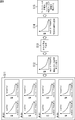
- step S11 MTF (Modulation Transfer Function) data is acquired at a predetermined image point.
- the MTF data is one index for evaluating the lens performance, and is data representing how faithfully the contrast of the subject can be reproduced by frequency characteristics.
- the graph of MTF data is a graph in which the horizontal axis is the spatial frequency and the vertical axis is the MTF data of the image formed by the lens, as shown in step S11 of FIG.
- the graph of the MTF data may be a graph in which the contrast reproduction rate (%) and the distance (mm) from the center of the screen are taken on the horizontal axis.
- the graph shown at step S11 in FIG. 9 is also on the lens image height 302 as described with reference to FIG. 6, and the four image points A and B on the X and Y axes. The description will be continued assuming that MTF data in the sagittal direction and the tangential direction are acquired from the image point C and the image point D, respectively.
- MTF data as well as PSF data, has anisotropy at the same image point, so it differs depending on the direction and also at different image points. Therefore, the MTF data is acquired from a plurality of directions at the same image point as the PSF data, and the MTF data is acquired from different image points within the same lens.
- step S11 of FIG. 9 the description will be continued here assuming that eight MTF data are acquired. A method for determining the image point from which the MTF data is acquired will be described later.
- step S12 averaging is performed using all of the obtained MTF data. In this case, an average of 8 pieces of MTF data is obtained.
- step S13 approximation is performed using the averaged MTF data and one type of Gaussian function.
- the approximation coefficient of the Gaussian function is obtained by solving the least square method of the averaged MTF data and the Gaussian function.
- step S14 MTF data approximated to isotropic MTF data is obtained.
- step S15 lens aberration correction filter coefficients are obtained by solving a Wiener filter from MTF data approximated to isotropic MTF data.
- PSF data and MTF data obtained from a plurality of image points on the lens and from different angles of one image point are averaged, and the averaged data is used to calculate An approximate value of PSF data or MTF data at a predetermined image height is obtained. Then, the lens aberration correction filter coefficient is calculated using the obtained approximate value and the Wiener filter.
- the lens aberration correction filter coefficient calculated from the predetermined image height and the calculation using the lens aberration correction filter coefficient at the predetermined image height have been described with reference to FIGS. Omitted.
- Image height for calculating lens aberration correction filter coefficient As described above, at a predetermined image height, a lens aberration correction filter coefficient to be applied to a pixel located at the image height is calculated. A plurality of image heights are selected for one lens, and a lens aberration correction filter coefficient is calculated at each image height.
- image height pixels for which lens aberration correction filter coefficients are not set can be corrected by interpolation. Also, with reference to FIG. Since the image height for calculating the lens aberration correction filter coefficient is determined by a method as will be described, the interval between the selected image heights can be widened to some extent.
- the interval between the selected image heights can be equal, and the interval may be constant regardless of the lens.
- the number of lens aberration filter coefficients can be effectively reduced by detecting a characteristic image height as described with reference to FIG. An example of calculating the lens aberration correction filter coefficient of the image height will be described.
- FIG. 10 is a diagram showing a graph of MTF data.
- the vertical axis of the graph of MTF data shown in FIG. 10 represents MTF data, and the horizontal axis represents image height. Referring to the graph shown in FIG. 10, the MTF data changes depending on the image height and is not a constant value.
- the MTF data may change depending on the image height. Therefore, the image height that changes drastically is selected as the image height for calculating the lens aberration correction filter coefficient.
- the image height 0 is selected because it is the center position of the lens.
- the image height 2 is selected because it is the image height at which the MTF data falls. Since the distance between the image height 0 and the image height 2 is separated, the image height 1 is selected as the image height at the approximate center.
- Image height 3 is selected because it is a turning point where the MTF data once lowered at image height 2 rises again and falls again.
- the image height 4 is selected because it is the end of the lens.
- image points A to D in FIG. 6 are image points at the position of the image height 4
- MTF data is acquired from a plurality of positions on the lens corresponding to the image height 4, and the lens is processed by the above-described processing.
- An aberration correction filter coefficient is calculated.
- the MTF data is used, but PSF data may be used.
- the image height at which the shape of the PSF greatly changes may be selected.
- the image height for calculating the lens aberration correction filter coefficient an inflection point at which the MTF data changes rapidly is selected.
- the image height at that position is also selected as the image height for calculating the lens aberration correction filter coefficient.
- an additional image height may be selected so as to be an appropriate interval.
- a plurality of image points are selected from the image height selected in this way, and MTF data or PSF data is acquired from the selected image points, whereby lens aberration correction filter coefficients are calculated.
- MTF data graph and PSF data graph may vary depending on the lens. Therefore, by acquiring data for each lens, selecting an image height, and calculating a lens aberration correction filter coefficient, it is possible to calculate a lens aberration correction filter coefficient corresponding to a different characteristic for each lens. Therefore, the blur correction can be performed with higher accuracy.
- the lens aberration correction filter coefficient calculated in this way is calculated, for example, when the lens is manufactured, and is stored in association with the lens.
- the housing portion of the optical lens 111 is provided with a holding function such as a memory, and the lens aberration correction filter coefficient is obtained by the holding function. Is retained.
- the lens aberration correction filter coefficient is supplied from the external optical lens 111 side different from the signal processing unit 113.
- the lens aberration correction unit 221 may be configured to hold the lens aberration correction filter coefficient.
- the lens aberration correction filter coefficient may be calculated by the user when the imaging apparatus 100 is used, instead of being calculated when the optical lens 111 is manufactured.
- a test pattern or the like is captured by the user with the imaging apparatus 100, PSF data or MTF data is acquired from the captured image, and the lens aberration correction filter coefficient is calculated by the method described above. It is also possible to configure.
- the lens aberration correction filter coefficient when the lens aberration correction filter coefficient is calculated at the time of use, it is possible to appropriately update the lens aberration correction filter coefficient in accordance with a change in the use environment or a secular change. Further, when the optical lens 111 is a replaceable imaging device, the processing for calculating the lens aberration correction filter coefficient may be executed and held when the optical lens 111 is replaced. Is possible.
- a lens aberration correction filter coefficient is calculated and associated with the IP address and managed on the side where the optical lens 111 is manufactured.
- IPv6 Internet Protocol Version 6
- an IP address can be assigned to the optical lens 111.
- the optical lens 111 can be uniquely identified, for example, a manufacturing number may be used.
- lens aberration correction associated with an IP address, a manufacturing number, or the like is performed.
- the filter coefficient can be downloaded and stored on the imaging apparatus 100 side.
- the lens aberration correction filter coefficient is calculated for each optical lens 111 and supplied or held to the lens aberration correction unit 221 of the imaging apparatus 100.
- FIG. 11 is a diagram for explaining the position of the image height selected for calculating the lens aberration correction filter coefficient.
- FIG. 11 an example in which five image heights are selected is shown. These five locations correspond to the image heights 0 to 4 shown in FIG.
- a graph of MTF data is shown on the lower side of FIG. 11, and this graph is the same as the graph shown in FIG.
- the image height 0 in the graph shown in FIG. 10 is indicated as the image height ih0 in the graph shown in FIG. Similarly, the image height 1 is the image height ih1, the image height 2 is the image height ih2, the image height 3 is the image height ih3, and the image height 4 is the image height ih4.
- the image height ih4 is located on the image circle 303 of the optical lens 111.
- the lens aberration correction filter coefficients for the image heights ih0 to 4 are calculated and held.
- blur correction at the coordinates (x, y) of the optical lens 111 is performed based on the following equation (9). Since the lens correction filter coefficient is not set in the image height of the pixel located at the coordinates (x, y) to be corrected, the position is located at the coordinates (x, y) based on the following equation (9). The pixel value of the pixel to be calculated is calculated.
- deblur_r (x, y) represents a pixel value after correction at coordinates (x, y).
- ⁇ represents a blending coefficient.
- ih n indicates an image height position, and is, for example, the image heights ih0 to ih4 in FIG.
- deblur_ih n is an image heightmit in which an adjacent lens correction filter coefficient is set closer to the center of the lens than the coordinates (x, y), and the lens correction filter coefficient Filter set to the image height ihn.
- the pixel value calculated by applying ihn (i, j) to the pixel value Pr (i, j) of the pixel located at the coordinates (x, y) is represented.
- deblur_ih n + 1 is an image height ihn + 1 in which an adjacent lens correction filter coefficient is set on the side farther from the center of the lens than the coordinates (x, y), and is set to the image height ihn + 1.
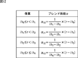
- the blend coefficient ⁇ is described as ⁇ 10 , ⁇ 21 , ⁇ 32 , and ⁇ 43 in the upper diagram of FIG. That is, when the image height between the image height ih0 to image height ih1 are is used blending coefficient alpha 10, when the image height between the image height ih1 to image height ih2 is blending coefficient alpha 21 is used, when the image height between the image height ih2 to image height ih3, the blend coefficient alpha 32 is used when the image height between the image height ih3 to image height ih4, the blend coefficient alpha 43 is used.
- the blend coefficient ⁇ is calculated according to the image height, as shown in FIG. 12, instead of using the same value between adjacent image heights for which the lens aberration correction filter coefficients are set. Position of the pixel to be corrected, the distance r from the center of the optical lens 111, the distance r is is a image height ih0 above, is smaller than the image height IH1, blending coefficient alpha 10 is calculated. The blending coefficient alpha 10 from a distance r, a value obtained by subtracting the image height Ih0, are divided by the value obtained by subtracting the image height Ih0 from the image height IH1.
- the blend coefficient ⁇ 21 is calculated.
- the blending coefficient alpha 21 from a distance r, a value obtained by subtracting the image height IH1, is a value obtained by dividing the value obtained by subtracting the image height IH1 from the image height ih2.
- Blend coefficient alpha 32 is a value obtained by dividing the value obtained by subtracting the image height ih2 from the distance r by the value obtained by subtracting the image height ih2 from the image height ih3.
- the blend coefficient ⁇ 43 is a value obtained by dividing the value obtained by subtracting the image height ih3 from the distance r by the value obtained by subtracting the image height ih3 from the image height ih4.
- the blend coefficient ⁇ is a value calculated by using the image height in which two lens aberration correction filter coefficients adjacent to the position of the pixel to be corrected are set. That is, the blend coefficient ⁇ is a value calculated by performing a linear calculation according to the distance r (x, y) from the center of the optical lens 111, as shown in FIG.
- the pixel value deblur_r (x, y) after the correction of the distance r (x, y) from the center of the optical lens 111 is the lens aberration correction filter coefficient that is before and after the position of the distance r Is applied to the pixel value Pr to be corrected, and the pixel value deblur_ih after the filter application is applied to the image height ih n and the image height ih n + 1.
- n is calculated using pixel value deblur_ih n + 1 .
- the lens correction filter coefficient that is set to the image height adjacent to the image height of the pixel that is the correction target is applied to the pixel value of the pixel that is the correction target.
- Lens aberration correction is performed by blending the corrected pixel value calculated in accordance with the image height position of the pixel for which no lens aberration correction filter coefficient is set.
- An xy address indicating the coordinate position of each pixel associated with the pixel value of each pixel is supplied from the image sensor 112 to the image height calculation unit 201.
- the image height calculation unit 201 derives the distance r (x, y) from the center of the optical lens 111, that is, the image height, from the supplied xy address.
- the blend coefficient calculation unit 202 sets the blend coefficient ⁇ corresponding to the image height calculated by the image height calculation unit 201 to the distance r (x, y from the center of the optical lens 111 as described with reference to FIG. ) Is calculated by a linear calculation according to).
- the calculated blend coefficient ⁇ is supplied to the blend processing unit 222 of the lens aberration correction processing unit 204.
- the lens aberration correction unit 221 of the lens aberration correction processing unit 204 acquires the supplied lens aberration correction filter coefficient, and the acquired lens The blur correction of the pixel value to be processed is performed using the aberration correction filter coefficient.
- the lens aberration correction unit 221 calculates the pixel value deblur ih n and the pixel value deblur ih n + 1 in Equation (9).
- the lens aberration correction unit 221 performs a convolution operation that multiplies the pixel values of the pixels included in the 7 ⁇ 7 pixels by each coefficient of the lens aberration correction filter coefficient and adds them. Then, the correction pixel value of the center pixel is calculated.
- the blend processing unit 222 uses the two corrected pixel values supplied from the lens aberration correction unit 221 and the blend coefficient ⁇ supplied from the blend coefficient calculation unit 202 to perform a calculation based on Expression (9), The pixel value after final lens aberration correction is calculated and output to the edge / flat portion blend processing unit 206.
- the lens aberration correction unit 221 blend processing using the corrected pixel value is performed, and the final lens aberration corrected pixel value for the pixel to be corrected An example in which is calculated is shown.
- the lens correction filter coefficient set at each image height position is blended using the blend coefficient ⁇ , the lens correction filter coefficient after blending is calculated, and the lens correction filter coefficient after blending is used.
- the lens aberration correction corresponding to the image height may be performed by performing the filtering process.
- correction is performed by calculation based on the following equation (10).
- Filter blend (i, j) represents a lens correction filter coefficient to be applied to a pixel to be corrected.
- FilterIND represents the lens correction filter coefficient set to the image heightIND
- FilterIND + 1 represents the lens correction filter coefficient set to the image heightIND + 1.
- the image heightIND and the image height ihn + 1 are image heights adjacent to the image height of the pixel to be corrected.
- the pixel to be corrected A lens correction filter coefficient to be applied is calculated.
- the blend coefficient ⁇ used for the blend is a coefficient calculated as described with reference to FIG. 12, and is calculated and used in the same manner as described above.
- Deblur r (x, y) represents the pixel value after correction of the pixel to be corrected. It is calculated by using the lens correction filter coefficient Filter blend (i, j) after blending for the pixel value of the pixel to be corrected.
- the lens aberration correction unit 221 performs correction after the filter coefficient is blended in the blend processing unit 222.
- lens aberration correction processing optimized for the MTF characteristics of the lens. Further, lens aberration correction corresponding to the image height can be performed without using a large-scale system. As a result, it is possible to correct lens aberration corresponding to image height in an image sensor (imaging device) that cannot use a large-scale system.
- Approximating the PSF data with a function enables the circuit to be scaled down, and enables the creation of lens aberration correction filter coefficients that suppress the effects of manufacturing variations.
- the series of processes described above can be executed by hardware or can be executed by software.
- a program constituting the software is installed in the computer.
- the computer includes, for example, a general-purpose personal computer capable of executing various functions by installing various programs by installing a computer incorporated in dedicated hardware.
- FIG. 13 is a block diagram showing an example of the hardware configuration of a computer that executes the above-described series of processing by a program.
- a CPU Central Processing Unit
- ROM Read Only Memory
- RAM Random Access Memory
- An input / output interface 1005 is further connected to the bus 1004.
- An input unit 1006, an output unit 1007, a storage unit 1008, a communication unit 1009, and a drive 1110 are connected to the input / output interface 1005.
- the input unit 1006 includes a keyboard, a mouse, a microphone, and the like.
- the output unit 1007 includes a display, a speaker, and the like.
- the storage unit 1008 includes a hard disk, a nonvolatile memory, and the like.
- the communication unit 1009 includes a network interface.
- the drive 1110 drives a removable medium 1111 such as a magnetic disk, an optical disk, a magneto-optical disk, or a semiconductor memory.
- the CPU 1001 loads, for example, the program stored in the storage unit 1008 to the RAM 1003 via the input / output interface 1005 and the bus 1004 and executes the program. Is performed.
- the program executed by the computer (CPU 1001) can be provided by being recorded on, for example, a removable medium 1111 as a package medium or the like.
- the program can be provided via a wired or wireless transmission medium such as a local area network, the Internet, or digital satellite broadcasting.
- the program can be installed in the storage unit 1008 via the input / output interface 1005 by attaching the removable medium 1111 to the drive 1110. Further, the program can be received by the communication unit 1009 via a wired or wireless transmission medium and installed in the storage unit 1008. In addition, the program can be installed in advance in the ROM 1002 or the storage unit 1008.
- the program executed by the computer may be a program that is processed in time series in the order described in this specification, or in parallel or at a necessary timing such as when a call is made. It may be a program for processing.
- system represents the entire apparatus composed of a plurality of apparatuses.
- this technology can also take the following structures.
- An acquisition unit that acquires a filter that performs blur correction set to each of a plurality of image heights;
- An image processing apparatus comprising: a correction unit that corrects a pixel value of a pixel at an image height to be corrected using the filter acquired by the acquisition unit.
- the correction unit is Applying the filter set to an image height adjacent to the image height that is the correction target to a pixel value of the pixel that is the correction target;
- a coefficient is calculated from the positional relationship between the image height that is the correction target and the adjacent image height,
- the image processing apparatus according to (1), wherein a pixel value after correction is calculated using the pixel value after application of the filter and the coefficient.
- the correction unit is A coefficient is calculated from the positional relationship between the image height that is the correction target and the adjacent image height, Using the filter set to an image height adjacent to the image height that is the correction target and the coefficient, a filter that is applied to the pixel value of the pixel that is the correction target is generated, The image processing apparatus according to (1), wherein a corrected pixel value is calculated using the generated filter and a pixel value of the pixel to be corrected.
- the filter coefficients are: PSF (Point Spread Function) data is calculated from a plurality of image points on the first image height, The PSF data is averaged; The averaged PSF data is used and approximated by a predetermined function, The image processing apparatus according to any one of (1) to (3), wherein the coefficient is a coefficient calculated from the approximated PSF data. (5) The calculation of the coefficient of the filter uses a Wiener filter. The image processing apparatus according to (4). (6) The image processing apparatus according to (4) or (5), wherein the image height for which the filter is set is an image height at which the shape of the PSF changes greatly.
- PSF Point Spread Function
- the filter coefficients are: MTF (Modulation Transfer Function) data is calculated from a plurality of image points on the first image height, The MTF data is averaged; The averaged MTF data is used and approximated by a predetermined function, The image processing apparatus according to any one of (1) to (3), wherein the coefficient is a coefficient calculated from the approximated MTF data.
- the image processing apparatus according to (7) or (8), wherein the image height for which the filter is set is an inflection point of the MTF data.
- (12) An image sensor; An acquisition unit that acquires a filter that performs blur correction set to each of a plurality of image heights; An imaging apparatus comprising: a correction unit that corrects a pixel value of a pixel at an image height that is a correction target among pixels captured by the imaging device using the filter acquired by the acquisition unit.
- An acquisition unit that acquires a filter that performs blur correction set to each of a plurality of image heights; Using the filter acquired by the acquisition unit, a correction unit that corrects the pixel value of the pixel at the image height that is the correction target;
- An electronic device comprising: an image processing unit that performs predetermined image processing on the pixel value after correction from the correction unit.
- imaging device 111 optical lens, 112 image sensor, 113 signal processing unit, 131 image signal correction unit, 132 RGB signal processing unit, 201 image height calculation unit, 202 blend coefficient calculation unit, 203 line memory, 204 lens aberration correction processing Part, 205 edge detection part, 206 edge / flat part blend processing part
Landscapes
- Engineering & Computer Science (AREA)
- Multimedia (AREA)
- Signal Processing (AREA)
- Physics & Mathematics (AREA)
- General Physics & Mathematics (AREA)
- Theoretical Computer Science (AREA)
- Image Processing (AREA)
- Facsimile Image Signal Circuits (AREA)
- Studio Devices (AREA)
Abstract
La présente invention concerne un dispositif de traitement d'image, un procédé de traitement d'image, un dispositif d'imagerie, un instrument électronique, et un programme configuré pour corriger de façon adéquate le flou d'une image. La présente invention comprend une unité d'acquisition pour acquérir des filtres de correction de flou réglés à une pluralité de hauteurs d'image, et une unité de correction pour corriger la valeur de pixel d'un pixel à une hauteur d'image de correction désignée au moyen d'un filtre acquis par l'unité d'acquisition. L'unité de correction commande au filtre qui est réglé à une hauteur d'image proche de la hauteur d'image de correction désignée d'être réglé à une valeur de pixel d'un pixel de correction désigné, calcule un coefficient à partir de la relation de position de la hauteur d'image de correction désignée et de la hauteur d'image proche, et calcule une valeur de pixel corrigée au moyen de la valeur de pixel post-filtrage et du coefficient. Le procédé décrit peut être implémenté dans des dispositifs de traitement d'image, tels des caméras, qui traitent les images ayant été capturées.
Applications Claiming Priority (2)
| Application Number | Priority Date | Filing Date | Title |
|---|---|---|---|
| JP2014099459A JP2015216576A (ja) | 2014-05-13 | 2014-05-13 | 画像処理装置、画像処理方法、撮像装置、電子機器、並びにプログラム |
| JP2014-099459 | 2014-05-13 |
Publications (1)
| Publication Number | Publication Date |
|---|---|
| WO2015174257A1 true WO2015174257A1 (fr) | 2015-11-19 |
Family
ID=54479800
Family Applications (1)
| Application Number | Title | Priority Date | Filing Date |
|---|---|---|---|
| PCT/JP2015/062635 Ceased WO2015174257A1 (fr) | 2014-05-13 | 2015-04-27 | Dispositif de traitement d'image, procédé de traitement d'image, dispositif d'imagerie, instrument électronique, et programme |
Country Status (2)
| Country | Link |
|---|---|
| JP (1) | JP2015216576A (fr) |
| WO (1) | WO2015174257A1 (fr) |
Families Citing this family (6)
| Publication number | Priority date | Publication date | Assignee | Title |
|---|---|---|---|---|
| JP7059185B2 (ja) | 2016-08-16 | 2022-04-25 | ソニーセミコンダクタソリューションズ株式会社 | 画像処理装置、画像処理方法、および撮像装置 |
| JP6728365B2 (ja) | 2016-08-25 | 2020-07-22 | キヤノン株式会社 | 画像処理方法、画像処理装置、撮像装置、画像処理プログラム、記憶媒体 |
| WO2018037806A1 (fr) * | 2016-08-25 | 2018-03-01 | 富士フイルム株式会社 | Dispositif de traitement d'image, système de traitement d'image, procédé de traitement d'image, et programme de traitement d'image |
| JP7271604B2 (ja) * | 2020-06-02 | 2023-05-11 | 三菱電機株式会社 | 赤外線撮像装置 |
| JP6991371B1 (ja) * | 2020-06-02 | 2022-01-14 | 三菱電機株式会社 | 赤外線撮像装置 |
| US11546515B2 (en) * | 2021-04-30 | 2023-01-03 | Gramm Inc. | Method and apparatus of camera image correction using stored tangential and sagittal blur data and computer-readable recording medium |
Citations (3)
| Publication number | Priority date | Publication date | Assignee | Title |
|---|---|---|---|---|
| JP2002369071A (ja) * | 2001-06-08 | 2002-12-20 | Olympus Optical Co Ltd | 画像処理方法および、それを実装したデジタルカメラおよび、プログラム |
| JP2012015865A (ja) * | 2010-07-01 | 2012-01-19 | Canon Inc | 画像処理装置、画像処理方法 |
| JP2013055623A (ja) * | 2011-09-06 | 2013-03-21 | Sony Corp | 画像処理装置、および画像処理方法、情報記録媒体、並びにプログラム |
-
2014
- 2014-05-13 JP JP2014099459A patent/JP2015216576A/ja active Pending
-
2015
- 2015-04-27 WO PCT/JP2015/062635 patent/WO2015174257A1/fr not_active Ceased
Patent Citations (3)
| Publication number | Priority date | Publication date | Assignee | Title |
|---|---|---|---|---|
| JP2002369071A (ja) * | 2001-06-08 | 2002-12-20 | Olympus Optical Co Ltd | 画像処理方法および、それを実装したデジタルカメラおよび、プログラム |
| JP2012015865A (ja) * | 2010-07-01 | 2012-01-19 | Canon Inc | 画像処理装置、画像処理方法 |
| JP2013055623A (ja) * | 2011-09-06 | 2013-03-21 | Sony Corp | 画像処理装置、および画像処理方法、情報記録媒体、並びにプログラム |
Also Published As
| Publication number | Publication date |
|---|---|
| JP2015216576A (ja) | 2015-12-03 |
Similar Documents
| Publication | Publication Date | Title |
|---|---|---|
| JP6327922B2 (ja) | 画像処理装置、画像処理方法、およびプログラム | |
| US8482627B2 (en) | Information processing apparatus and method | |
| JP5188651B2 (ja) | 画像処理装置、およびそれを用いた撮像装置 | |
| JP4700445B2 (ja) | 画像処理装置および画像処理プログラム | |
| US9049356B2 (en) | Image processing method, image processing apparatus and image processing program | |
| JP5983373B2 (ja) | 画像処理装置、情報処理方法及びプログラム | |
| WO2015174257A1 (fr) | Dispositif de traitement d'image, procédé de traitement d'image, dispositif d'imagerie, instrument électronique, et programme | |
| WO2011145296A1 (fr) | Appareil de saisie d'image, appareil de traitement d'image, procédé de traitement d'image et programme de traitement d'image | |
| JP2014027570A (ja) | 画像処理方法、画像処理プログラム、画像処理装置および撮像装置 | |
| WO2011121760A9 (fr) | Appareil de traitement d'images et appareil de capture d'images le comprenant | |
| CN102111544A (zh) | 摄像模块、图像处理装置及图像记录方法 | |
| JP2013055623A (ja) | 画像処理装置、および画像処理方法、情報記録媒体、並びにプログラム | |
| JP5949201B2 (ja) | 画像処理装置及びプログラム | |
| JP5353945B2 (ja) | 画像処理装置および画像処理プログラム並びに電子カメラ | |
| JP5309940B2 (ja) | 画像処理装置、および撮像装置 | |
| JP6415108B2 (ja) | 画像処理方法、画像処理装置、撮像装置、画像処理プログラム、および、記憶媒体 | |
| JP4945942B2 (ja) | 画像処理装置 | |
| JP6436840B2 (ja) | 画像処理装置、撮像装置、画像処理方法、画像処理プログラム、および、記憶媒体 | |
| JP6255892B2 (ja) | 画像処理装置、画像処理方法、及びプログラム | |
| JP2010079815A (ja) | 画像補正装置 | |
| JP6238673B2 (ja) | 画像処理装置、撮像装置、撮像システム、画像処理方法、画像処理プログラム、および、記憶媒体 | |
| JP2017183775A (ja) | 画像処理装置、画像処理方法および撮像素子 | |
| JP6306811B2 (ja) | 画像処理装置、情報処理方法及びプログラム | |
| JP2017123532A (ja) | 画像処理装置、撮像装置、画像処理方法、画像処理プログラムおよび記録媒体 | |
| JP6604737B2 (ja) | 画像処理装置、撮像装置、画像処理方法、画像処理プログラム、および、記憶媒体 |
Legal Events
| Date | Code | Title | Description |
|---|---|---|---|
| 121 | Ep: the epo has been informed by wipo that ep was designated in this application |
Ref document number: 15792927 Country of ref document: EP Kind code of ref document: A1 |
|
| NENP | Non-entry into the national phase |
Ref country code: DE |
|
| 122 | Ep: pct application non-entry in european phase |
Ref document number: 15792927 Country of ref document: EP Kind code of ref document: A1 |