WO2015174339A1 - Dispositif d'affichage - Google Patents
Dispositif d'affichage Download PDFInfo
- Publication number
- WO2015174339A1 WO2015174339A1 PCT/JP2015/063302 JP2015063302W WO2015174339A1 WO 2015174339 A1 WO2015174339 A1 WO 2015174339A1 JP 2015063302 W JP2015063302 W JP 2015063302W WO 2015174339 A1 WO2015174339 A1 WO 2015174339A1
- Authority
- WO
- WIPO (PCT)
- Prior art keywords
- light
- display
- guide plate
- display device
- light guide
- Prior art date
- Legal status (The legal status is an assumption and is not a legal conclusion. Google has not performed a legal analysis and makes no representation as to the accuracy of the status listed.)
- Ceased
Links
Images


Classifications
-
- G—PHYSICS
- G09—EDUCATION; CRYPTOGRAPHY; DISPLAY; ADVERTISING; SEALS
- G09F—DISPLAYING; ADVERTISING; SIGNS; LABELS OR NAME-PLATES; SEALS
- G09F13/00—Illuminated signs; Luminous advertising
- G09F13/18—Edge-illuminated signs
Definitions
- the present invention relates to a display device capable of emitting and displaying the inside of a display window frame by irradiating light from light sources arranged on both sides in a circumferential direction to a display window portion of an arc-shaped frame body that is overlapped and fixed on a power pole.
- the power pole is used as a support for supporting the power transmission line, but on the surface of the power pole, a winding signboard displaying an advertisement of a company or a store is fixed and used.
- an advertisement for a company or a store is displayed on a telephone pole by assembling a sleeve signboard.
- an electric advertisement board with a built-in optical sensor and fluorescent lamp has been proposed (see Patent Document 1).
- an advertisement crime prevention light with an advertisement function and a lighting function added to a sleeve signboard has been proposed.
- a white light emitting diode is disposed opposite to the end of the light guide plate as a light source in the signboard display, and the light emitted from the white light emitting diode is incident from the end of the light guide plate and emitted from the plane of the light guide plate.
- An advertisement is displayed by placing the light-transmitting signboard on the outside of the light plate and back-lighting the light-transmitting signboard.
- a case is provided at the bottom of the signboard display, and a white light emitting diode is attached downward in the case to form a security light.
- the commercial power source is turned on and off based on the signal from the day / night sensor, and the commercial power source is converted to direct current to supply power to the signboard illumination light source and the crime prevention illumination light source (see Patent Document 2).
- the above-mentioned electric advertisement board and advertisement crime prevention light are provided as a sleeve signboard at a position protruding from the upper part of the utility pole using a fixture.
- the sleeve signboard looks good from a distance, but it is difficult for a pedestrian or person near the utility pole to notice and the display content is difficult to see.
- the advertisement wrapped around the utility pole is attached close to the level of the pedestrian's eyes, it has the advantages of high advertising and attracting customers and can be guided accurately.
- the advertisement wrapped around the utility pole is attached close to the level of the pedestrian's eyes, it has the advantages of high advertising and attracting customers and can be guided accurately.
- it does not require installation space because it is wound around a telephone pole, and there is no worry of being hit by strong winds.
- the object of the present invention is to solve the above-mentioned problems of the prior art, and is fixed to the power pole so that it can be visually recognized by a pedestrian, does not take up installation space, and brightly emits light at night, regardless of day or night.
- An object of the present invention is to provide a display device with enhanced advertisement display effect.
- a display device has the following configuration. That is, a mounting frame body that is curved and fixed in an overlapping manner on a power pole, and a display window is formed at the center of the front surface, and a display window portion is formed at the center of the front surface.
- a display frame body formed in an arc shape, and a frame body that is integrally assembled with the reflective surface of the mounting frame so as to reflect the transmitted light incident from the incident end surfaces on both sides in the circumferential direction.
- An arc-shaped light guide plate that emits surface light toward the display window, an arc-shaped transparent display plate that is disposed with a predetermined gap in front of the light guide plate and holds an advertising medium, and the mounting frame.
- the first spacer provided and the second spacer forming a gap between the transparent display plate and the light guide plate are diagonally sandwiched at a predetermined incident angle with respect to the incident end faces on both sides in the circumferential direction of the light guide plate.
- Incident surface is inclined with respect to the incident end surface so that it is incident
- a pair of LED light sources assembled together, and the display frame body and the transparent display plate are assembled along the peripheral edge of the display window, and the periphery of the transparent display plate faces the light guide plate.
- a support member that is pressed and supported, and a power supply unit that supplies power to the pair of LED light sources according to ambient brightness, and the pair of LEDs that are supplied with power from the power supply unit
- Each light source emits light and is incident at a predetermined incident angle from the incident end surface of the light guide plate, so that the transmitted light that passes through the light guide plate is irradiated with the reflected light reflected by the reflective surface to cause surface emission.
- the advertisement medium arranged in front of the display window is caused to emit light from the display window.
- the advertising medium disposed in front by causing the light guide plate to emit light can be displayed and emitted from the display window, so that the advertisement display effect can be maintained regardless of day or night.
- the light guide plate that emits light at night emits light from the display window to the surroundings, so that it can also serve as a streetlight.
- the posture of the pair of LED light sources can be maintained and incident on the incident end face of the light guide plate with a predetermined incident angle instead of being perpendicular, the amount of transmitted light transmitted through the light guide plate can be increased.
- the entire surface of the curved light guide plate can be brightly surface-emitted by the reflected light from the reflecting surface.
- a gap between the display frame body and the transparent display plate is sealed with a sealing material.
- reinforcing members extending in the circumferential direction are provided at a plurality of locations in the length direction of the utility pole, and the frame body is provided with a fixing band that passes through a band hole provided in the reinforcing material. Is preferably attached and fixed around the electric pole.
- the mounting frame to which the light guide plate is assembled is reinforced by the reinforcing material, so that the frame, the light guide plate, the transparent display plate, etc. are not easily deformed when attached to the utility pole, and the band hole of the reinforcing material is formed by the fixing band. Since it is inserted and wound around the utility pole, it can be easily attached to and detached from the utility pole when changing the advertising medium.
- the utility pole has a tapered surface that tapers from the tip to the installation surface. If the fixed band is inserted into the band hole of the uppermost reinforcing material and fixed, the frame position is determined from the utility pole. By fixing at multiple locations, it will not slip off.
- the power supply unit is supplied with commercial power from the utility pole, converts the voltage to supply DC power, and supplies power to the LED light source when the surroundings are dark to automatically turn on the power source under predetermined conditions.
- the automatic flasher that shuts off and automatically turns off, and the commercial power supply is taken into the power supply circuit by the automatic flasher and DC power is supplied to the pair of LED light sources.
- an automatic flasher e.g., an e-switch
- the automatic flasher is turned off during the daytime without supplying DC power to the pair of LED light sources.
- the power supply is turned on, a commercial power supply is taken into the power supply circuit, a DC power supply is supplied to the pair of LED light sources, and the light guide plate emits light. Thereby, useless power consumption can be eliminated and the advertisement display effect can be maintained regardless of day or night.
- the display device described above is fixed to the outer peripheral surface of a columnar column, and is electrically connected to the photovoltaic panel, the photovoltaic panel, and the pair of LED light sources.
- the controller may be assembled, and when the amount of power generated by the photovoltaic power generation panel falls below a predetermined voltage, the controller discharges from the charging battery and causes the pair of LED light sources to emit light for a predetermined time.
- the display device can be installed on any support (cylindrical column) other than a utility pole with a solar panel or controller to effectively display advertisements in the evening or at night, or to turn on the streetlight, and replace the battery. Since it can be used by supplying power from natural energy without having to do it step by step, energy saving effects can be expected.
- the advertisement display effect is enhanced regardless of day and night by being superposed on the power pole and fixed at a height that can be visually recognized by pedestrians, and does not take up installation space and brightly emits light at night.
- a display device can be provided.
- a display device that is mounted on the outer peripheral surface of a utility pole and causes a light guide plate to emit light and display an advertisement medium disposed in front from a display window will be described.
- a frame body 2 is provided that is superposed on the power pole 1 and curved and fixed.
- the size of the frame body 2 varies, but for example, it is attached in the circumferential direction of the utility pole 1 in a range of approximately 90 ° to 100 °.
- a metal plate such as stainless steel is bent and used.
- the frame body 2 includes an attachment frame body 3 that is fixed to the power pole 1 in an overlapping manner and has a reflection surface 3a formed on the outer surface.
- a matte type white paint is applied to form a reflective surface 3a.
- a white sheet or the like may be attached instead of the white paint.
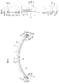
- the outer peripheral edge portion in the circumferential direction of the mounting frame 3 is formed with a bent portion 3b bent forward at an acute angle (see FIG. 1A).
- the outer peripheral edge in the longitudinal direction of the mounting frame 3 is formed with a bent portion 3c that is bent at a substantially right angle toward the front (see FIG. 1B).
- the display frame 4 has a display window 4a formed at the center of the front surface, and has a side surface 4b whose outer peripheral edge in the circumferential direction is bent at an obtuse angle (see FIG. 1A).
- the outer peripheral edge portion in the longitudinal direction of the display frame body 4 is formed with a bent portion 4c that is bent at a substantially right angle toward the front (see FIG. 1B).
- the display frame 4 is overlapped so as to cover the mounting frame 3 so that the side surface portion 4b overlaps with the bent portion 3b on both sides in the circumferential direction and the bent portion 4c overlaps with the bent portion 3c on both sides in the longitudinal direction.
- the fixing bolt 5a is fixed to the screw hole penetrating the side surface portion 4b and the bent portion 3b
- the fixing bolt 5b is fixed to the screw hole penetrating the side surface portion 4c and the bent portion 3c.
- the display frame body 4 is assembled integrally to form a frame-shaped frame body 2 curved in the circumferential direction (see FIG. 2B).
- the light guide plate 6 formed in an arc shape is superimposed on the reflection surface 3a of the mounting frame 3 and integrally assembled by adhesion or the like, and emits surface light toward the display window portion 4a.
- an acrylic resin plate formed in an arc shape is preferably used.
- An LED light source 7 is provided in each space portion surrounded by the reflection surface 3a and the bent portion 3b of the mounting frame 3. The pair of LED light sources 7 are assembled with the irradiation surface inclined with respect to the incident end surface 6a so that the light incident plate 6 is incident on the incident end surface 6a at a predetermined incident angle with both circumferential end surfaces of the light guide plate 6 in the circumferential direction. ing.
- the pair of LED light sources 7 is diagonally formed by a first spacer 8 provided in the mounting frame 3 and a second spacer 9 that forms a gap between the transparent display plate 10 and the light guide plate 6. It is sandwiched and assembled in an inclined posture.
- a light shielding material 6b (for example, a light shielding metal tape) is attached to the outer peripheral surface (the portion hidden by the display frame body 4) in the vicinity of the incident end face 6a of the light guide plate 6 to increase incident light incident on the light guide plate 6. It is preferable to do so.
- metal bars for example, stainless steel round bars having different diameters are used.
- the LED light source 7 If the LED light source 7 is disposed so as to face the incident end face 6a, the incident light enters the incident end face perpendicularly and travels straight through the light guide plate 6 to diffuse the incident light without being reflected by the reflecting face 3a. Therefore, the transmitted light does not reach the central portion of the light guide plate 6 and becomes dark. For this reason, it is necessary to make incident light incident on the LED light source 7 so that the light emitting surface faces the reflecting surface 3a so as to have a predetermined incident angle with respect to the incident end surface 6a. Needless to say, it is necessary to set the incident angle of incident light to be smaller than the angle (critical angle) at which the incident end face 6a totally reflects.
- the posture of the pair of LED light sources 7 can be maintained and incident on the incident end surface 6a of the light guide plate 6 with a predetermined incident angle instead of being perpendicular, so that the transmitted light transmitted through the light guide plate 6 can be transmitted.
- the light guide plate 6 can be brightly surface-emitted with the reflected light from the reflecting surface 3a.
- the pair of LED light sources 7 uses the light guide plate 6 and the transparent display plate 10 in the frame 2 (the mounting frame 3 and the display frame 4), the first and second spacers 8 and 9, the backup material 14, and the like. After assembling, for example, it is inserted into the frame 2 from the lower side in the longitudinal direction and assembled.
- Various thicknesses of the LED light source 7 are used. However, since the LED light source 7 is incident on the incident end surface 6a of the light guide plate 6 and is held down by the second spacer 9, the plate of the light guide plate 6 is maintained. It is preferable to use the same thickness.
- an arc-shaped transparent display plate 10 that holds an advertising medium 11 is disposed in front of the light guide plate 6.
- the transparent display board 10 an acrylic resin board is used suitably.
- the advertising medium 11 is pasted on the back side of the transparent display board 10 and displayed on the display window 4a.
- the advertising medium 11 may be affixed to the front surface side of the transparent display board 10, it can be displayed more clearly when it is affixed to the back side.
- the transparent display plate 10 is longer than the light guide plate 6 in the circumferential direction, and is provided with a predetermined gap 13 between the light guide plate 6 and the second spacer 8. Further, as shown in FIG.
- third spacers 21 are respectively provided inside the bent portions 3 c provided at both ends in the longitudinal direction of the mounting frame 3, and between the transparent display plate 10 and the light guide plate 6.
- Fourth spacers 22 are provided at both ends in the longitudinal direction.
- a space for wiring is provided at the upper end in the longitudinal direction of the mounting frame 3, and a drain hole (not shown) is provided at the lower end in the longitudinal direction.
- the transparent display board 10 is supported by inserting a backup material 14 (support member) between the display frame 4 and pressing the periphery (four sides) of the transparent display board 10 toward the light guide plate 6. Specifically, the transparent display board 10 is sandwiched and supported between the first spacer 8 by a backup material 14 that is elastic with the display frame 4.
- the backup material 14 is preferably an elastic member such as a foam material, a silicon rubber material, a metal coil, or the like.
- the gap between the display frame 4 and the transparent display plate 10 is sealed by the sealing material 15 around the display window portion 4a.
- the sealing material 15 only needs to maintain waterproofness and dustproofness, and may be a resin material such as silicon rubber, an adhesive, or the like. Thereby, even if a display apparatus is exposed to a wind and rain, invasion of a water drop etc. can be prevented into the LED light source 7, and a weather resistance can be improved.
- a power supply unit 16 that supplies power to the pair of LED light sources 7 is provided on the upper side surface portion 4b of the display frame 4.
- the power supply unit 16 is supplied with commercial power (100 V) from the utility pole 1 and performs voltage conversion to supply DC power (12 V), and automatically turns on when the surroundings are darkened. It is equipped with an e-switch (automatic flasher) that automatically turns off when the set time or brightness is detected.
- the power supply unit 16 takes in a commercial power supply into a power supply circuit based on a detection signal for detecting the night of the day / night sensor, and supplies DC power to the pair of LED light sources 7.
- the power supply unit 16 is housed in a metal (for example, stainless steel) power supply case 17.
- the power supply case 17 is assembled by fitting a fixing bolt 17c into a screw hole penetrating an inner case body 17a having an opening portion and an outer case body 17b having an opening portion. Further, the power supply case 17 is assembled integrally with the frame body 2 by superimposing the inner case body 17a on the side surface portion 4b of the display frame body 4 and fitting the fixing bolts 17d into the threaded holes that pass therethrough.
- a wiring hole 17 e for taking in the power supply line 18 (see FIG. 3A) from the utility pole 1 is provided at the bottom of the power supply case 17.
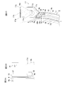
- the mounting surface 3d of the mounting frame 3 is provided with reinforcing members 19 extending in the circumferential direction at a plurality of locations in the length direction of the utility pole 1 (three locations in FIG. 1B). ing.
- the reinforcing member 19 is a metal band-like material (for example, a stainless steel band-like material) similar to the attachment frame 3, and is formed in an arc shape like the attachment frame 3, by resistance welding or the like to the attachment frame 3. They are joined together.
- the length of the reinforcing member 19 in the circumferential direction is shorter than the length of the mounting frame 3.
- Both ends of the reinforcing member 19 are respectively formed with bent portions 19a bent in the radial direction of the utility pole 1, and each bent portion 19a is formed with a band hole 19b (see FIGS. 1B and 2C).
- the fixed band 20 (see FIG. 4) is inserted into the band hole 19 and is wound around the outer peripheral surface of the utility pole 1 so that the bent portions 19a provided on both sides bite the utility pole 1 and the display device is It is fixed to the utility pole 1.
- the attachment frame 3 to which the light guide plate 6 is assembled is reinforced by the reinforcing material 19, when the display device is attached to the utility pole 1, the frame 2 is hardly deformed and the LED light source 7 is not displaced.
- the light guide plate 6 and the transparent display plate 10 are not easily deformed.
- the fixing band 20 is inserted through the band hole 19b of the reinforcing member 19 and is wound around and fixed to the utility pole 1, it is easy to attach and remove the frame 2 to the utility pole 1 when changing the advertising medium 11. Can be done.
- the electric pole 1 has a tapered surface that is tapered from the tip toward the installation surface, when the fixing band 20 is inserted into and fixed to the band hole 19b of the uppermost reinforcing member 19, the frame 2 becomes the electric pole 1.
- the height position is determined, and it will not slip off by fixing at multiple locations.
- FIG. 4 shows a state where the display device is attached to the utility pole 1.
- the advertising medium 11 is held on the transparent display board 10 and the arc-shaped frame 2 is fixed to the utility pole 2, the advertising medium 11 is passed from a passerby or vehicle by the reflected light from the sunlight reflecting surface 3a against a white background in the daytime. Easy to see.
- the e switch provided in the power supply unit 16 is turned on and power supply to the pair of LFD light sources 7 is started.
- the pair of LED light sources 7 transmitted light that is incident on the incident end face 6 a from both sides in the circumferential direction of the light guide plate 6 at a predetermined incident angle is transmitted while being reflected by the light guide plate 6 and reflected from the reflective surface 3 a.
- the advertising medium 11 disposed in front by causing the light guide plate 6 to emit light by the reflected light from the reflecting surface 3a can be emitted and displayed from the display window portion 4a. Can be maintained.
- the light guide plate 6 that emits light at night emits light from the display window portion 4a to the surroundings (for example, the brightness of the LED light source 7 is 350 lux to 380 lux), so that it can also serve as a streetlight.
- a display device that is fixed to the power pole 1 so as to be visually recognized by a pedestrian, has an installation effect and does not take up installation space, and brightly emits light at night to enhance the advertisement display effect regardless of day or night Can be provided.
- the said display apparatus was fixed to the utility pole 1, and was comprised so that it might be electrically fed from an electric wire and light-emitted, it is not limited to this aspect.
- the display device described above may be fixed by being overlapped on the outer peripheral surface of a columnar column.
- a solar power generation panel for example, power generation amount 30 W
- a controller electrically connected to the solar power generation panel and the LED light source need to be assembled to the support column.
- the controller may be configured to discharge from the charging battery and cause the pair of LED light sources to emit light for a predetermined time when the amount of power generated by the photovoltaic power generation panel becomes a predetermined voltage or lower (for example, 5 V or lower). Accordingly, since the display device can be used by supplying power from natural energy even in a place where there is no power supply facility, versatility is enhanced and an energy saving effect can be expected.
Landscapes
- Physics & Mathematics (AREA)
- General Physics & Mathematics (AREA)
- Engineering & Computer Science (AREA)
- Theoretical Computer Science (AREA)
- Illuminated Signs And Luminous Advertising (AREA)
Abstract
La présente invention vise à pourvoir à un dispositif d'affichage qui est fixé au sommet d'un pylône à une hauteur le rendant visible même pour un piéton, qui n'a pas besoin d'un espace d'installation et qui renforce les effets de l'affichage des publicités de jour comme de nuit car il émet une lumière vive à partir d'une surface lorsqu'il fait nuit. Pour cela, une paire de sources de lumière à LED (7) sert à émettre de la lumière qui frappe selon un angle d'incidence imposé une face de bord incident (6a) sur l'un ou l'autre des côtés d'une plaque de guidage de lumière (6) de manière à ce que, dans la lumière transmise traversant la plaque de guidage de lumière (6), la lumière réfléchie qui est réfléchie sur le côté d'une surface de réflexion (3a) rayonne vers l'avant, ce qui provoque l'émission de la lumière à partir d'une surface, et un support publicitaire (11) disposé devant est éclairé ainsi et affiché à travers une section fenêtre d'affichage (4a).
Applications Claiming Priority (2)
| Application Number | Priority Date | Filing Date | Title |
|---|---|---|---|
| JP2014-099808 | 2014-05-13 | ||
| JP2014099808A JP5610499B1 (ja) | 2014-05-13 | 2014-05-13 | 表示装置 |
Publications (1)
| Publication Number | Publication Date |
|---|---|
| WO2015174339A1 true WO2015174339A1 (fr) | 2015-11-19 |
Family
ID=52574624
Family Applications (1)
| Application Number | Title | Priority Date | Filing Date |
|---|---|---|---|
| PCT/JP2015/063302 Ceased WO2015174339A1 (fr) | 2014-05-13 | 2015-05-08 | Dispositif d'affichage |
Country Status (2)
| Country | Link |
|---|---|
| JP (1) | JP5610499B1 (fr) |
| WO (1) | WO2015174339A1 (fr) |
Cited By (1)
| Publication number | Priority date | Publication date | Assignee | Title |
|---|---|---|---|---|
| JP6022101B1 (ja) * | 2016-07-04 | 2016-11-09 | 有限会社エーユー建築工房 | 表示装置 |
Families Citing this family (4)
| Publication number | Priority date | Publication date | Assignee | Title |
|---|---|---|---|---|
| JP6519349B2 (ja) * | 2015-06-26 | 2019-05-29 | オムロン株式会社 | 導光板 |
| JP6519350B2 (ja) * | 2015-06-26 | 2019-05-29 | オムロン株式会社 | 装飾装置及び遊技機 |
| JP6067918B1 (ja) * | 2016-09-28 | 2017-01-25 | 有限会社エーユー建築工房 | 表示装置 |
| JP7116431B2 (ja) * | 2019-01-24 | 2022-08-10 | 株式会社ゼロ・サム | 表示装置、その表示装置の製造方法、表示システム |
Citations (12)
| Publication number | Priority date | Publication date | Assignee | Title |
|---|---|---|---|---|
| JPH0473012U (fr) * | 1990-11-06 | 1992-06-26 | ||
| JPH0485376U (fr) * | 1990-11-29 | 1992-07-24 | ||
| JP2000056716A (ja) * | 1998-08-07 | 2000-02-25 | Shinei Kk | 面発光型コードレス表示装置 |
| JP2004062139A (ja) * | 2002-06-07 | 2004-02-26 | Toyoda Gosei Co Ltd | ライトガイド |
| JP2004317976A (ja) * | 2003-04-18 | 2004-11-11 | Toyoda Gosei Co Ltd | ライトガイド |
| JP2006215432A (ja) * | 2005-02-07 | 2006-08-17 | Fujiden Keiso Kk | 照明装置 |
| JP3144232U (ja) * | 2008-06-09 | 2008-08-21 | 中電興業株式会社 | 広告防犯灯 |
| JP2008290569A (ja) * | 2007-05-24 | 2008-12-04 | West Japan Railway Co | 発光式鉄道用看板 |
| JP2009155957A (ja) * | 2007-12-27 | 2009-07-16 | Sekisui Jushi Co Ltd | 自発光装置 |
| JP2010033862A (ja) * | 2008-07-29 | 2010-02-12 | Shikoku Instrumentation Co Ltd | 屋外用led照明パネル |
| JP2012013777A (ja) * | 2010-06-29 | 2012-01-19 | Aisin Seiki Co Ltd | 装飾構造体 |
| JP2012141342A (ja) * | 2010-12-28 | 2012-07-26 | Sumitomo Bakelite Co Ltd | 表示用パネル |
Family Cites Families (1)
| Publication number | Priority date | Publication date | Assignee | Title |
|---|---|---|---|---|
| JP2012141341A (ja) * | 2010-12-28 | 2012-07-26 | Sumitomo Bakelite Co Ltd | 表示用パネル |
-
2014
- 2014-05-13 JP JP2014099808A patent/JP5610499B1/ja active Active
-
2015
- 2015-05-08 WO PCT/JP2015/063302 patent/WO2015174339A1/fr not_active Ceased
Patent Citations (12)
| Publication number | Priority date | Publication date | Assignee | Title |
|---|---|---|---|---|
| JPH0473012U (fr) * | 1990-11-06 | 1992-06-26 | ||
| JPH0485376U (fr) * | 1990-11-29 | 1992-07-24 | ||
| JP2000056716A (ja) * | 1998-08-07 | 2000-02-25 | Shinei Kk | 面発光型コードレス表示装置 |
| JP2004062139A (ja) * | 2002-06-07 | 2004-02-26 | Toyoda Gosei Co Ltd | ライトガイド |
| JP2004317976A (ja) * | 2003-04-18 | 2004-11-11 | Toyoda Gosei Co Ltd | ライトガイド |
| JP2006215432A (ja) * | 2005-02-07 | 2006-08-17 | Fujiden Keiso Kk | 照明装置 |
| JP2008290569A (ja) * | 2007-05-24 | 2008-12-04 | West Japan Railway Co | 発光式鉄道用看板 |
| JP2009155957A (ja) * | 2007-12-27 | 2009-07-16 | Sekisui Jushi Co Ltd | 自発光装置 |
| JP3144232U (ja) * | 2008-06-09 | 2008-08-21 | 中電興業株式会社 | 広告防犯灯 |
| JP2010033862A (ja) * | 2008-07-29 | 2010-02-12 | Shikoku Instrumentation Co Ltd | 屋外用led照明パネル |
| JP2012013777A (ja) * | 2010-06-29 | 2012-01-19 | Aisin Seiki Co Ltd | 装飾構造体 |
| JP2012141342A (ja) * | 2010-12-28 | 2012-07-26 | Sumitomo Bakelite Co Ltd | 表示用パネル |
Cited By (5)
| Publication number | Priority date | Publication date | Assignee | Title |
|---|---|---|---|---|
| JP6022101B1 (ja) * | 2016-07-04 | 2016-11-09 | 有限会社エーユー建築工房 | 表示装置 |
| WO2018008173A1 (fr) * | 2016-07-04 | 2018-01-11 | 有限会社エーユー建築工房 | Dispositif d'affichage |
| CN107578716A (zh) * | 2016-07-04 | 2018-01-12 | 有限公司Au建筑工作室 | 显示装置 |
| TWI621109B (zh) * | 2016-07-04 | 2018-04-11 | Yugen Kaisha Au Architecture Studio | 顯示裝置 |
| US10553136B2 (en) | 2016-07-04 | 2020-02-04 | Yugen Kaisha Au Architecture Studio | Display apparatus |
Also Published As
| Publication number | Publication date |
|---|---|
| JP5610499B1 (ja) | 2014-10-22 |
| JP2015215570A (ja) | 2015-12-03 |
Similar Documents
| Publication | Publication Date | Title |
|---|---|---|
| US9214101B2 (en) | Backlit graphic display device | |
| JP5610499B1 (ja) | 表示装置 | |
| US20090175047A1 (en) | Auxiliary luminous trim strip of a car lamp | |
| JP2010033862A (ja) | 屋外用led照明パネル | |
| US7217015B2 (en) | Device for properly illuminating at least one flag, including the United States flag | |
| KR101642412B1 (ko) | 지주형 도로 시설물 | |
| JP2012014834A (ja) | Ledエッジライトにより発光する防水性面発光板 | |
| JP2012141342A (ja) | 表示用パネル | |
| KR20150131793A (ko) | 행인들의 시선을 유도하여 광고효과를 향상토록 한 돌출간판 | |
| JP3089260U (ja) | マンホール蓋及びマンホールの照明装置並びにマンホールの標識具 | |
| KR101007772B1 (ko) | 엘이디가 장착된 시선유도표지 | |
| KR102357183B1 (ko) | 조명표지판 | |
| JP3186591U (ja) | 情報表示部付照明装置 | |
| KR20150039914A (ko) | 솔라셀 광고장치 | |
| KR20090001502U (ko) | 로고 표시 판넬의 양면발광 조명장치 | |
| JP2008129785A (ja) | 誘導標識装置 | |
| JP5603312B2 (ja) | 停電時対応型自発光標識 | |
| KR101884669B1 (ko) | 엘이디 안내판 | |
| JP3144232U (ja) | 広告防犯灯 | |
| JP2013079498A (ja) | 逆光対策道路標識板 | |
| KR20140136121A (ko) | 태양광 발전을 사용하는 엘이디램프와 축광 발광제를 활용한 무전력 도로 안내용 표지봉 | |
| KR101056118B1 (ko) | 채널 변환 방식의 el 시트를 채택한 조명 도로표지판 | |
| KR101030620B1 (ko) | 태양광을 이용한 간판 | |
| RU2710115C1 (ru) | Дорожный знак с внутренней подсветкой | |
| JP2009098421A (ja) | 案内表示板、並びに案内表示灯 |
Legal Events
| Date | Code | Title | Description |
|---|---|---|---|
| 121 | Ep: the epo has been informed by wipo that ep was designated in this application |
Ref document number: 15792653 Country of ref document: EP Kind code of ref document: A1 |
|
| NENP | Non-entry into the national phase |
Ref country code: DE |
|
| 122 | Ep: pct application non-entry in european phase |
Ref document number: 15792653 Country of ref document: EP Kind code of ref document: A1 |