WO2015174406A1 - Unité optique, et endoscope équipé de cette unité optique - Google Patents
Unité optique, et endoscope équipé de cette unité optique Download PDFInfo
- Publication number
- WO2015174406A1 WO2015174406A1 PCT/JP2015/063611 JP2015063611W WO2015174406A1 WO 2015174406 A1 WO2015174406 A1 WO 2015174406A1 JP 2015063611 W JP2015063611 W JP 2015063611W WO 2015174406 A1 WO2015174406 A1 WO 2015174406A1
- Authority
- WO
- WIPO (PCT)
- Prior art keywords
- holding frame
- unit
- lens
- imaging element
- lens holding
- Prior art date
- Legal status (The legal status is an assumption and is not a legal conclusion. Google has not performed a legal analysis and makes no representation as to the accuracy of the status listed.)
- Ceased
Links
Images






Classifications
-
- G—PHYSICS
- G02—OPTICS
- G02B—OPTICAL ELEMENTS, SYSTEMS OR APPARATUS
- G02B23/00—Telescopes, e.g. binoculars; Periscopes; Instruments for viewing the inside of hollow bodies; Viewfinders; Optical aiming or sighting devices
- G02B23/24—Instruments or systems for viewing the inside of hollow bodies, e.g. fibrescopes
- G02B23/2476—Non-optical details, e.g. housings, mountings, supports
-
- A—HUMAN NECESSITIES
- A61—MEDICAL OR VETERINARY SCIENCE; HYGIENE
- A61B—DIAGNOSIS; SURGERY; IDENTIFICATION
- A61B1/00—Instruments for performing medical examinations of the interior of cavities or tubes of the body by visual or photographical inspection, e.g. endoscopes; Illuminating arrangements therefor
-
- A—HUMAN NECESSITIES
- A61—MEDICAL OR VETERINARY SCIENCE; HYGIENE
- A61B—DIAGNOSIS; SURGERY; IDENTIFICATION
- A61B1/00—Instruments for performing medical examinations of the interior of cavities or tubes of the body by visual or photographical inspection, e.g. endoscopes; Illuminating arrangements therefor
- A61B1/00002—Operational features of endoscopes
- A61B1/00043—Operational features of endoscopes provided with output arrangements
- A61B1/00045—Display arrangement
-
- A—HUMAN NECESSITIES
- A61—MEDICAL OR VETERINARY SCIENCE; HYGIENE
- A61B—DIAGNOSIS; SURGERY; IDENTIFICATION
- A61B1/00—Instruments for performing medical examinations of the interior of cavities or tubes of the body by visual or photographical inspection, e.g. endoscopes; Illuminating arrangements therefor
- A61B1/005—Flexible endoscopes
-
- G—PHYSICS
- G02—OPTICS
- G02B—OPTICAL ELEMENTS, SYSTEMS OR APPARATUS
- G02B23/00—Telescopes, e.g. binoculars; Periscopes; Instruments for viewing the inside of hollow bodies; Viewfinders; Optical aiming or sighting devices
- G02B23/24—Instruments or systems for viewing the inside of hollow bodies, e.g. fibrescopes
-
- G—PHYSICS
- G02—OPTICS
- G02B—OPTICAL ELEMENTS, SYSTEMS OR APPARATUS
- G02B23/00—Telescopes, e.g. binoculars; Periscopes; Instruments for viewing the inside of hollow bodies; Viewfinders; Optical aiming or sighting devices
- G02B23/24—Instruments or systems for viewing the inside of hollow bodies, e.g. fibrescopes
- G02B23/26—Instruments or systems for viewing the inside of hollow bodies, e.g. fibrescopes using light guides
-
- H—ELECTRICITY
- H04—ELECTRIC COMMUNICATION TECHNIQUE
- H04N—PICTORIAL COMMUNICATION, e.g. TELEVISION
- H04N23/00—Cameras or camera modules comprising electronic image sensors; Control thereof
- H04N23/50—Constructional details
- H04N23/51—Housings
-
- H—ELECTRICITY
- H04—ELECTRIC COMMUNICATION TECHNIQUE
- H04N—PICTORIAL COMMUNICATION, e.g. TELEVISION
- H04N23/00—Cameras or camera modules comprising electronic image sensors; Control thereof
- H04N23/50—Constructional details
- H04N23/54—Mounting of pick-up tubes, electronic image sensors, deviation or focusing coils
-
- H—ELECTRICITY
- H04—ELECTRIC COMMUNICATION TECHNIQUE
- H04N—PICTORIAL COMMUNICATION, e.g. TELEVISION
- H04N23/00—Cameras or camera modules comprising electronic image sensors; Control thereof
- H04N23/50—Constructional details
- H04N23/55—Optical parts specially adapted for electronic image sensors; Mounting thereof
-
- A—HUMAN NECESSITIES
- A61—MEDICAL OR VETERINARY SCIENCE; HYGIENE
- A61B—DIAGNOSIS; SURGERY; IDENTIFICATION
- A61B1/00—Instruments for performing medical examinations of the interior of cavities or tubes of the body by visual or photographical inspection, e.g. endoscopes; Illuminating arrangements therefor
- A61B1/00064—Constructional details of the endoscope body
- A61B1/00071—Insertion part of the endoscope body
- A61B1/0008—Insertion part of the endoscope body characterised by distal tip features
- A61B1/00097—Sensors
-
- A—HUMAN NECESSITIES
- A61—MEDICAL OR VETERINARY SCIENCE; HYGIENE
- A61B—DIAGNOSIS; SURGERY; IDENTIFICATION
- A61B1/00—Instruments for performing medical examinations of the interior of cavities or tubes of the body by visual or photographical inspection, e.g. endoscopes; Illuminating arrangements therefor
- A61B1/00163—Optical arrangements
-
- A—HUMAN NECESSITIES
- A61—MEDICAL OR VETERINARY SCIENCE; HYGIENE
- A61B—DIAGNOSIS; SURGERY; IDENTIFICATION
- A61B1/00—Instruments for performing medical examinations of the interior of cavities or tubes of the body by visual or photographical inspection, e.g. endoscopes; Illuminating arrangements therefor
- A61B1/04—Instruments for performing medical examinations of the interior of cavities or tubes of the body by visual or photographical inspection, e.g. endoscopes; Illuminating arrangements therefor combined with photographic or television appliances
- A61B1/044—Instruments for performing medical examinations of the interior of cavities or tubes of the body by visual or photographical inspection, e.g. endoscopes; Illuminating arrangements therefor combined with photographic or television appliances for absorption imaging
-
- H—ELECTRICITY
- H04—ELECTRIC COMMUNICATION TECHNIQUE
- H04N—PICTORIAL COMMUNICATION, e.g. TELEVISION
- H04N23/00—Cameras or camera modules comprising electronic image sensors; Control thereof
- H04N23/50—Constructional details
- H04N23/555—Constructional details for picking-up images in sites, inaccessible due to their dimensions or hazardous conditions, e.g. endoscopes or borescopes
Definitions
- the present invention relates to an optical unit used for an endoscope, in which a lens frame and an element frame are fitted and fixed.
- An optical unit such as an imaging unit for capturing an optical image can be introduced from the outside of the living body or structure to observe a difficult part such as the inside of the living body or the inside of the structure.
- the provided endoscope is used in the medical field or the industrial field, for example.
- An optical unit such as an imaging unit of an endoscope includes an objective lens that forms a subject image, and generally a CCD (charge coupled device) and a CMOS (complementary metal oxide semiconductor) disposed on the imaging surface of the objective lens.
- An image sensor such as a sensor is provided.
- an imaging unit as disclosed in Japanese Patent Laid-Open No. 2002-238837 is known.
- a lens frame and an element frame are fitted to each other, and a thermosetting type is used. It is bonded and fixed by a soldering material such as an adhesive or solder.
- the lens when the lens frame and the element frame are fitted and fixed at the focal position of the lens so as to coincide with the light receiving portion of the image sensor, the lens includes a bonding material generated during the curing process of the bonding material. Due to the expansion and contraction of the frame and the element frame, a predetermined fitting position between the lens frame and the element frame is shifted and fixed, so that there is a problem that a desired optical performance cannot be obtained.
- high-temperature and high-pressure sterilization is performed before and after use in medical devices such as endoscopes.
- the endoscope is exposed to a high temperature, so that the optical unit also becomes a high temperature, the bonding material for bonding and fixing the lens frame and the element frame is softened, and a predetermined fitting position of the lens frame and the element frame is set. There was a problem that it might shift.
- the diameter of the insertion portion has been reduced in order to increase the number of pixels of the endoscope image to be photographed and to improve the insertability, and an imaging unit equipped with a high-resolution image sensor is used. Or a small one is used, so even if the fitting position shift between the lens frame and the element frame is very small, the optical performance conformity quality is not satisfied or the optical performance is degraded. There is a new problem of inviting
- the present invention has been made in view of the above-described circumstances, and the lens frame and the element frame are fixed without being displaced at a predetermined fitting position even in a high temperature environment such as during manufacture and high temperature and high pressure sterilization. It is an object of the present invention to provide an optical unit that maintains the above-described state, satisfies the conformity of optical performance, and prevents deterioration of the optical performance, and an endoscope including the optical unit.
- An optical unit detects a subject image formed by the objective optical system by fitting a cylindrical lens holding frame that holds an objective optical system and the lens holding frame to be fitted.
- a cylindrical imaging device holding frame that holds an imaging device having a light receiving unit, and the lens holding frame and the lens holding frame at a fitting position where the imaging surface of the subject image by the objective optical system coincides with the light receiving unit A gap formed between the lens holding frame and the imaging device holding frame, and a welded portion provided at a fitting portion between the lens holding frame and the imaging device holding frame for fixing the imaging device holding frame. And a bonding material to be filled.
- An optical unit detects a subject image formed by the objective optical system by fitting the cylindrical lens holding frame that holds the objective optical system and the lens holding frame to be fitted.
- a cylindrical image sensor holding frame that holds an image sensor having a light receiving section, and the lens holding frame at a fitting position in which the imaging surface of the subject image by the objective optical system and the light receiving section coincide with each other.
- the lens in the fitting portion between the lens holding frame and the image sensor holding frame so as to fix the image sensor holding frame and fill a gap formed between the lens holding frame and the image sensor holding frame.
- a welded portion formed by welding at a plurality of locations continuously without a gap around the outer periphery of the holding frame.
- An endoscope detects a subject image formed by the objective optical system by fitting a cylindrical lens holding frame that holds an objective optical system and the lens holding frame to be fitted.
- a cylindrical image sensor holding frame that holds an image sensor having a light receiving section, and the lens holding frame at a fitting position in which the imaging surface of the subject image by the objective optical system and the light receiving section coincide with each other.
- an optical unit provided with a bonding material for filling.
- An endoscope includes a cylindrical lens holding frame that holds an objective optical system and an object image that is formed by the objective optical system, with the lens holding frame interpolated and fitted.
- a cylindrical image sensor holding frame for holding an image sensor having a light receiving portion to detect, and the lens holding frame at a fitting position where the imaging surface of the subject image by the objective optical system is matched with the light receiving portion And the image sensor holding frame are fixed, and the fitting portion between the lens holding frame and the image sensor holding frame is filled so as to fill a gap formed between the lens holding frame and the image sensor holding frame.
- an optical unit including a welded portion formed by welding at a plurality of locations continuously without a gap around the outer periphery of the lens holding frame.
- the lens frame and the element frame are maintained in a fixed state without being displaced at a predetermined fitting position even in a high-temperature environment such as during manufacturing and during high-temperature and high-pressure sterilization. It is possible to provide an optical unit that satisfies the quality of performance adaptation and prevents deterioration of the optical performance, and an endoscope including the optical unit.
- the cross-sectional view showing the configuration of the optical unit in a state where the lens unit and the imaging element unit are fitted and fixed to each other The cross-sectional view showing the configuration of the optical unit in a state where the lens unit of the first modification and the imaging element unit are fitted and fixed to each other Sectional drawing which shows the state before the lens unit and image pick-up element unit of a 2nd modification are fitted similarly
- the cross-sectional view showing the configuration of the optical unit in a state where the lens unit and the image sensor unit are fitted to each other The cross-sectional view showing the configuration of the optical unit in a state where the lens unit and the imaging element unit are fitted and fixed to each other FIG.
- FIG. 6 is a cross-sectional view showing the configuration of the optical unit in a state where the lens unit of the third modification and the image sensor unit are fitted and fixed to each other.
- the cross-sectional view which shows the structure of the optical unit of the state which the lens unit and image pick-up element unit which concern on 3rd Embodiment were fitted and fixed Similarly, the cross-sectional view showing the configuration of the optical unit in a state where the lens unit of the modification and the image sensor unit are fitted and fixed
- FIG. 1 is a diagram showing the configuration of the endoscope
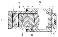
- FIG. 2 is a cross-sectional view showing the configuration of the optical unit
- FIG. 3 is a cross-sectional view showing the configuration of the optical unit along the line III-III in FIG. 4 is a cross-sectional view showing a state before the lens unit and the image sensor unit are fitted
- FIG. 5 is a cross-sectional view showing a state in which the lens unit and the image sensor unit are fitted and fixed by a weld
- FIG. FIG. 7 is a cross-sectional view showing a configuration of the optical unit of the first modification
- FIG. 8 is a cross-sectional view of the optical unit of the second modification.
- FIG. 9 is a transverse sectional view showing the structure of the optical unit of the third modification
- FIG. 10 is a longitudinal sectional view showing the structure of the optical unit of the fourth modification
- FIG. FIG. 12 is a longitudinal sectional view showing the configuration of the optical unit of the reference example of FIG.
- FIG. 13 is a longitudinal sectional view showing the configuration of the optical unit of the third reference example
- FIG. 14 is a longitudinal sectional view showing the configuration of the optical unit of the fourth reference example.
- FIG. 15 is a longitudinal sectional view showing the configuration of the optical unit of the fifth reference example.
- the endoscope 101 of the present embodiment has a configuration that can be introduced into a subject such as a human body and optically images a predetermined observation site in the subject.
- the subject into which the endoscope 101 is introduced is not limited to a human body, and may be another living body or an artificial object such as a machine or a building.
- the endoscope 101 is a universal as a composite cable extending from the insertion portion 102 introduced into the subject, an operation portion 103 positioned at the proximal end of the insertion portion 102, and a side portion of the operation portion 103.
- the code 104 is mainly composed.
- the insertion portion 102 includes a distal end portion 110 disposed at the distal end, a bendable bending portion 109 disposed on the proximal end side of the distal end portion 110, and an operation portion 103 disposed on the proximal end side of the bending portion 109.
- a flexible tube portion 108 having flexibility is connected to the tip end side of the tube.
- the endoscope 101 may have a form called a so-called rigid endoscope that does not include a flexible portion in the insertion portion 102.
- the imaging unit 1 is provided at the distal end portion 110.
- the operation unit 103 is provided with an angle operation knob 106 for operating the bending of the bending unit 109.
- an endoscope connector 105 connected to the external device 120 is provided.
- the external device 120 to which the endoscope connector 105 is connected is connected to an image display unit 121 such as a monitor via a cable.
- the endoscope 101 includes an optical fiber bundle (not shown) that transmits illumination light from a universal cord 104, an operation unit 103, an electric cable 115 inserted into the insertion unit 102, and a light source unit provided in the external device 120. )have.
- the electric cable 115 is configured to electrically connect the endoscope connector 105 and the imaging unit 1. By connecting the endoscope connector 105 to the external device 120, the imaging unit 1 is electrically connected to the external device 120 via the electric cable 115.
- the power supply from the external device 120 to the imaging unit 1 and the communication between the external device 120 and the imaging unit 1 are performed via the electric cable 115.
- the external device 120 is provided with an image processing unit.
- the image processing unit generates a video signal based on the image sensor output signal output from the imaging unit 1 and outputs the video signal to the image display unit 121. That is, in this embodiment, an optical image (endoscopic image) captured by the imaging unit 1 is displayed on the image display unit 121 as a video.
- the endoscope 101 is not limited to the configuration connected to the external device 120 or the image display unit 121, and may be configured to include a part or all of the image processing unit or the monitor, for example.
- the optical fiber bundle is configured to transmit light emitted from the light source unit of the external device 120 to the illumination window as the illumination light emitting unit of the tip part 110.
- the light source unit may be arranged on the operation unit 103 or the distal end portion 110 of the endoscope 101.
- the configuration of the imaging unit 1 as an optical unit provided at the distal end portion 110 will be described.
- the direction from the imaging unit 1 toward the subject along the photographing optical axis O of the subject image is referred to as the front end, the front side, or the object side, and the opposite direction is the base end, the rear side, or the image.
- the side is sometimes referred to as the side.
- the imaging unit 1 that is the optical unit of the present embodiment includes a lens unit 10 and an imaging element unit 20 in order from the front object side.
- the lens unit 10 includes a cylindrical lens holding frame 11 as a lens frame, and a plurality of objective lens groups 13 as an objective optical system held by the lens holding frame 11.
- the imaging element unit 20 includes a cylindrical imaging element holding frame 12 as an element frame, an optical member 14 such as a transparent glass plate and a cover glass 22, and an imaging element 21.
- a cover glass 22 as a transparent cover body for protecting the light receiving portion 21a of the image sensor 21 is attached to the optical member 14 of the image sensor unit 20 with an optical adhesive or the like.
- the optical member 14 is fitted and fixed to the image sensor holding frame 12. That is, in the image sensor unit 20, the image sensor holding frame 12 on the distal end side holds the image sensor 21 on the proximal end side via the optical member 14 and the cover glass 22.
- an image pickup board portion on which a rectangular light receiving portion 21a is mounted is connected to an electric cable 115 via an electronic board portion 24 such as an FPC. Note that a plurality of electronic components 25 are mounted on the electronic substrate unit 24.
- the image pickup device 21 is a device in which a plurality of elements that output electric signals corresponding to incident light indicated by the photographing optical axis O are arranged at a predetermined timing in a planar light receiving unit.
- a format called a CMOS (complementary metal oxide semiconductor) sensor, or other various types are applied.
- the outer periphery of the fitting portion of the lens holding frame 11 of the lens unit 10 and the inner periphery of the fitting portion of the imaging element holding frame 12 of the image sensor unit 20 are fitted and fixed.
- the image pickup device 21 is arranged so that the above-described light receiving portion 21a is positioned on the imaging surface of the objective lens group 13 of the lens unit 10.
- the imaging unit 1 is provided with a heat-shrinkable tube 15 for fixing the tip portion to the outer frame portion of the imaging element holding frame 12 to form an exterior and holding the watertight inside.
- the imaging unit 1 is filled with a filler 26 such as an adhesive that covers the imaging element 21, the electronic substrate 24, and the like in the heat shrinkable tube 15, and the inside is kept watertight.
- a filler 26 such as an adhesive that covers the imaging element 21, the electronic substrate 24, and the like in the heat shrinkable tube 15, and the inside is kept watertight.
- the imaging unit 1 is fitted so that the fitting part of the lens holding frame 11 of the lens unit 10 is inserted into the fitting part of the imaging element holding frame 12 of the imaging element unit 20. Are combined. At this time, the fitting is performed so that the outer circumference of the fitting portion of the lens holding frame 11 and the center of the inner circumference of the fitting portion of the image sensor holding frame 12 are coincident.
- the center of the outer periphery of the fitting part of the lens holding frame 11 and the center of the inner periphery of the fitting part of the image sensor holding frame 12 is the optical axis O of the subject image passing through the objective lens group 13 held by the lens holding frame 11. Is consistent with
- the fitting part of the lens holding frame 11 and the image sensor holding frame 12 is in a state of being fitted to each other, and here is joined by one welded part 30 and a minute gap in a part where they overlap each other.
- the bonding material 31 such as an adhesive is filled so as to be filled and fixed in an airtight (watertight) state.
- the lens holding frame 11 is inserted into the image sensor holding frame 12 from a state where they are separated from each other, as shown in FIG.
- the lens holding frame 11 is moved back and forth on the object side and the image side along the longitudinal direction along the photographing optical axis O with respect to the image sensor holding frame 12, and the lens holding frame 11 is moved by the objective lens group 13.
- the predetermined fitting position with respect to the image sensor holding frame 12 is adjusted such that the light image formation surface coincides with the light receiving portion 21 a of the image sensor 21 held by the image sensor holding frame 12.
- the lens unit 10 and the image sensor unit 20 have a so-called in-focus position in which the subject image collected by the objective lens group 13 detected by the element group arranged in the light receiving portion 21a of the image sensor 21 has a predetermined optical performance.
- a predetermined fitting position in the longitudinal direction between the lens holding frame 11 and the image sensor holding frame 12 is adjusted so that a focused subject image is obtained.
- the lens unit 10 and the image pickup device unit 20 are fixed with a jig (not shown) so that the fitting position of the fitting portion between the lens holding frame 11 and the image pickup device holding frame 12 is not shifted.
- a welded portion 30 welded to each other by, for example, laser welding by laser beam irradiation is formed in the middle part of the outer periphery of the image pickup device holding frame 12, so that the lens holding frame 11 and the image pickup device holding frame are 12 is fixed so as not to move.
- the lens unit 10 and the image sensor unit 20 are, for example, a thermosetting type so as to fill a minute gap generated in the fitting portion between the lens holding frame 11 and the image sensor holding frame 12.
- the bonding material 31 that is an adhesive is filled. Note that the bonding material 31 is applied along the object-side end surface of the fitting portion of the image sensor holding frame 12, so that the bonding material 31 penetrates into a minute gap by a so-called capillary phenomenon.
- the lens unit 10 and the image sensor unit 20 are subjected to a thermosetting process for curing the bonding material 31 filled in the gap between the fitting portions of the lens holding frame 11 and the image sensor holding frame 12.
- the fitting position between the lens holding frame 11 of the lens unit 10 and the imaging element holding frame 12 of the imaging element unit 20 is fixed by the welding portion 30, and the lens holding frame 11 and the imaging element holding are fixed. It has a configuration in which it is fixed in an airtight (watertight) manner by a bonding material 31 that is filled and cured in a gap where the frames 12 overlap.
- the imaging unit 1 is strong at a position where the lens unit 10 and the imaging element unit 20 satisfy the predetermined optical performance where the focal position of the objective lens group 13 and the light receiving part 21a of the imaging element 21 coincide with each other by the welding part 30. It is configured to be airtight (watertight) bonded by the bonding material 31.
- the imaging unit 1 configured as described above is manufactured at the time of manufacturing, when the bonding material 31 for bonding the lens unit 10 and the imaging element unit 20 in an airtight (watertight) manner is thermoset, and for the endoscope 101 at a high temperature and a high pressure. Even when the bonding material 31, the lens holding frame 11, and the image sensor holding frame 12 are expanded and contracted during sterilization (autoclave processing), the lens holding frame 11 and the image sensor holding frame 12 are firmly fixed by the welding portion 30. Therefore, the lens unit 10 and the image sensor unit 20 are prevented from being displaced.
- the imaging unit 1 maintains the fixed state without shifting the predetermined fitting position of the lens unit 10 and the imaging element unit 20 even in a high-temperature environment such as manufacturing and high-temperature / high-pressure sterilization disinfection. It is possible to satisfy the conforming quality of the optical performance and to prevent deterioration of the optical performance.
- the welding part 30 which fixes so that the lens holding frame 11 of the lens unit 10 and the image pick-up element holding frame 12 of the image pick-up element unit 20 may not slip
- deviate is not limited to laser welding, but various welding, such as ultrasonic welding and spot welding. A method may be applied.
- the welding portion 30 for fixing the lens holding frame 11 and the image pickup device holding frame 12 is at a position where the image height of the light receiving portion 21a of the image pickup device 21 is low, that is, the light receiving portion 21a is rectangular here. Therefore, it is preferable to form it on an extended line at a position facing the center of any side of the light receiving portion 21a.
- the imaging unit 1 If a part of the objective lens group 13 that is close to and faces the welded portion 30 is deformed, a subject image that is distorted by the refraction of the light at the deformed portion may be formed on the light receiving portion 21a.
- the welded portion 30 for fixing the lens holding frame 11 and the imaging device holding frame 12 is formed on an extension line facing a position where the image height of the light receiving portion 21 a of the imaging device 21 is low. Even if the objective lens group 13 in that portion is deformed, the influence of the distortion of the subject image in the range imaged on the light receiving portion 21a can be reduced as much as possible.
- the imaging unit 1 is joined to the proximal outer peripheral portion of the fitting portion of the lens holding frame 11 of the lens unit 10 or the inner peripheral portion of the distal end of the fitting portion of the imaging device holding frame 12 of the imaging element unit 20 at the time of manufacture.
- the lens holding frame 11 and the image sensor unit 20 may be fitted to form the welded portion 30, and finally the bonding material 31 may be subjected to a thermosetting process.
- Imaging unit 1 may have various modified examples described below.
- the fitting unit of the lens holding frame 11 of the lens unit 10 and the fitting unit of the imaging device holding frame 12 of the imaging device unit 20 are formed by welding.
- Two welded portions 30a and 30b are formed at positions that are symmetrical with respect to the center of the fitting portion between the lens holding frame 11 and the image sensor holding frame 12 (a point through which the imaging optical axis O passes).
- the two welded portions 30 a and 30 b for fixing the lens holding frame 11 and the imaging device holding frame 12 are on an extension line facing a position where the image height of the light receiving portion 21 a of the imaging device 21 is low. It is formed at the position.
- the lens unit 10 and the image sensor unit 20 are formed simultaneously by the two welded portions 30a and 30b, so that the outer diameter center of the fitting portion of the lens holding frame 11 and the inner diameter of the fitting portion of the image sensor holding frame 12 are formed.
- the lens holding frame 11 and the image sensor holding frame 12 can be fixed without shifting the center.
- the imaging unit 1 configured as described above forms two welded portions 30a and 30b, so that the lens unit 10 and the imaging device unit 20 have the focal position of the objective lens group 13 and the light receiving portion 21a of the imaging device 21. It becomes the structure fixed more firmly in the position which satisfies the corresponding predetermined optical performance.
- the imaging unit 1 of the present modification includes four welded portions 30 a to 30 d for fixing the lens holding frame 11 and the imaging element holding frame 12, and the lens holding frame 11 and the imaging element holding frame 12. Are formed at equal intervals around the center of the fitting portion.
- the two welded portions 30a and 30b are formed at symmetrical positions of the center points of the fitting portions of the lens holding frame 11 and the image sensor holding frame 12 as in the first modification.
- the two welded portions 30c and 30d are positions rotated by 90 degrees around the center of the fitting portion between the lens holding frame 11 and the image sensor holding frame 12 with respect to the other two welded portions 30a and 30b.
- the lens holding frame 11 and the image sensor holding frame 12 are formed at symmetrical positions of the center point of the fitting portion.
- the two welded portions 30 for fixing the lens holding frame 11 and the image sensor holding frame 12 are also opposed to a position where the image height of the light receiving unit 21a of the image sensor 21 is low. It is formed at a position on the extension line.
- the imaging unit 1 configured as described above forms four welded portions 30a to 30d, so that the lens unit 10 and the imaging element unit 20 have the focal position of the objective lens group 13 and the light receiving portion 21a of the imaging element 21. It becomes the structure fixed more firmly in the position which satisfies the corresponding predetermined optical performance.
- the lens holding frame 11 and the image sensor holding frame 12 may be fixed by a plurality of, here, twelve welded portions 30 a to 30 j in the imaging unit 1 of this modification.
- the plurality of welded portions 30a to 30j are preferably formed at even intervals around the center of the fitting portion between the lens holding frame 11 and the image sensor holding frame 12 by an even number.
- the welded portions 30a to 30b are formed so that the two are paired so as to face each other at a symmetrical position of the center point of the fitting portion of the lens holding frame 11 and the image sensor holding frame 12. .
- the welded portion 30 that fixes the lens holding frame 11 and the imaging device holding frame 12 is the tip of the fitting portion of the imaging device holding frame 12 and holds the imaging device.
- the frame 12 is formed at an edge portion (edge portion) of a part of the front end surface.
- the imaging unit 1 configured in this manner does not form the welded portion 30 in the middle of the fitting portion of the imaging element holding frame 12, the bonding material 31 overlaps the lens holding frame 11 and the imaging element holding frame 12. Therefore, the lens unit 10 and the image sensor unit 20 can be joined in an airtight (watertight) manner more reliably.
- the imaging unit 1 may be configured as various reference examples described below in addition to the modifications described above.
- the bonding material 31 that joins the lens unit 10 and the imaging device unit 20 in an airtight (watertight) manner is an edge portion of a part of the front end surface of the fitting portion of the imaging device holding frame 12. It is good also as a structure apply
- the imaging unit 1 functions as a bonding material reservoir (adhesion reservoir) into which extra adhesive or the like as a bonding material 31 that joins the lens unit 10 and the imaging element unit 20 in an airtight (watertight) manner flows.
- a recess-shaped circumferential groove 12 a may be formed in the inner peripheral portion of the image sensor holding frame 12.
- the circumferential groove 12a is provided in the inner peripheral portion on the proximal end side from the fitting portion of the image sensor holding frame 12, but not limited to this, the fitting portion of the image sensor holding frame 12 is provided. You may form in the inner peripheral part.
- the imaging unit 1 functions as a bonding material reservoir (adhesion reservoir) into which extra adhesive or the like as a bonding material 31 that joins the lens unit 10 and the imaging element unit 20 in an airtight (watertight) manner flows.
- a recess-shaped circumferential groove 11 a may be formed on the outer periphery of the lens holding frame 11.
- the circumferential groove 11a is provided in the outer peripheral portion of the fitting portion of the lens holding frame 11.
- the present invention is not limited to this, and the outer peripheral portion on the base end side from the fitting portion of the lens holding frame 11 is provided. You may form in.
- the imaging unit 1 is on the distal end side from the fitting portion of the imaging element holding frame 12 of the imaging element unit 20, and the distal end of the imaging element frame is formed on the tapered surface 12 b to capture the lens unit 10 and the imaging unit 1.
- a bonding material 31 for bonding the element unit 20 in an airtight (watertight) manner is also filled in the distal end portion of the imaging element holding frame 12 formed by the tapered surface 12b so as to cover the entire circumference of the distal end of the imaging element unit 20. It is good also as a structure which improved airtightness (watertightness).
- the front end surface of the image sensor holding frame 12 is the tapered surface 12b, so that the filling work of the bonding material 31 can be easily performed.
- the imaging unit 1 is provided with a flange portion 11b on the distal end side of the fitting portion of the lens holding frame 11 of the lens unit 10, and a base end surface of the flange portion 11b is formed on a tapered surface 11c.
- the bonding material 31 for bonding the lens unit 10 and the image sensor unit 20 in an airtight (watertight) manner is also filled between the tapered surface 12b and the front end surface of the image sensor holding frame 12 so that the entire periphery of the front end of the image sensor unit 20 is obtained. It is good also as a structure which improved airtightness (watertightness) so that it may cover.
- the base end surface of the flange portion 11b of the lens holding frame 11 is the tapered surface 11c, so that the filling work of the bonding material 31 is facilitated.
- FIG. 16 is a cross-sectional view showing the configuration of the optical unit in a state in which the lens unit and the image sensor unit are fitted
- FIG. 17 is an optical unit in a state in which the lens unit and the image sensor unit are fitted and fixed
- FIG. 18 is a cross-sectional view showing the structure of the optical unit in a state where the lens unit of the first modification and the image pickup device unit are fitted and fixed
- FIG. 19 is the second modification.
- FIG. 20 is a cross-sectional view showing a state before the lens unit and the image sensor unit are fitted together
- FIG. 20 is a cross-sectional view showing the configuration of the optical unit in a state where the lens unit and the image sensor unit are fitted
- FIG. 22 is a cross-sectional view showing the configuration of the optical unit in a state where the lens unit and the image sensor unit are fitted and fixed, and FIG. 22 shows the lens unit and image sensor unit of the third modification fitted. It is a cross-sectional view showing the configuration of an optical unit of a fixed state.
- the lens holding frame 11 and the imaging element holding frame 12 of the imaging element unit 20 may have a slight gap, and the welded portion 30 contracts during solidification, so that the center of the outer diameter of the fitting portion of the lens holding frame 11 of the lens unit 10 and the image sensor
- the center of the inner diameter of the fitting portion of the image sensor holding frame 12 of the unit 20 is decentered and displaced, and the lens unit 10 is located at a predetermined position with respect to the image sensor unit 20 in a direction perpendicular to the imaging optical axis O. There is a case where it is fixed and shifted.
- the fitting portion of the lens holding frame 11 of the lens unit 10 is eccentric with respect to the fitting portion of the imaging element holding frame 12 of the imaging element unit 20, in the direction orthogonal to the photographing optical axis O.
- the center of the objective lens group 13 held by the lens holding frame 11 of the lens unit 10 is displaced from a predetermined position with respect to the image sensor unit 20.
- the photographing optical axis O of the subject image is deviated from a predetermined imaging center position of the light receiving portion 21a of the image pickup device 21 provided in the image pickup device holding frame 12 of the image pickup device unit 20, here the center of the light receiving portion 21a.
- the conformity quality of the predetermined optical performance cannot be obtained.
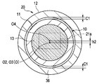
- the lens holding hole for holding the lens is displaced from the inner diameter center O2 by a predetermined distance h1.
- the inner diameter center O2 of the lens holding frame 11 coincides with the center of the objective lens group 13 to be held, that is, the photographing optical axis O of the subject image.
- the lens holding frame 11 has a configuration in which the inner peripheral surface of the lens holding hole is shifted to a predetermined distance h1 with respect to the outer peripheral surface of the fitting portion, and the respective centers are eccentric. That is, in the lens unit 10, the inner diameter center O2 of the lens holding hole for holding the objective lens group 13 of the lens holding frame 11 is predetermined by a predetermined distance h1 with respect to the outer diameter center O1 of the fitting portion of the lens holding frame 11. The configuration is eccentric in the direction.
- the lens holding frame 11 has a minimum thickness portion 18 having a predetermined thickness d1, and a predetermined thickness d2 (a point symmetric position with respect to the minimum thickness portion 18 is greater than the predetermined thickness d1).
- the maximum thickness portion 19 has d1 ⁇ d2).
- the predetermined distance h ⁇ b> 1 is between the outer peripheral surface of the fitting portion of the lens holding frame 11 and the inner peripheral surface of the fitting portion of the imaging device holding frame 12 in a state where the lens unit 10 is inserted into the imaging device unit 20. Is set to be substantially the same distance (h1 ⁇ C1) as the clearance C1 as a minute gap formed in the circumferential direction.
- the imaging unit 1 configured as described above includes the maximum thickness portion 19 side of the fitting portion of the lens holding frame 11, as shown in FIG. 17.
- a welded portion 30 is formed in the middle of the outer periphery of the fitting portion of the image sensor holding frame 12 to be fixed so that the lens holding frame 11 and the image sensor holding frame 12 do not move.
- the lens holding frame 11 is contracted when the welded portion 30 is solidified, and the maximum thickness portion 19 of the fitting portion of the lens holding frame 11 is fitted to the image sensor holding frame 12.
- the outer peripheral surface of the maximum thickness portion 19 is imaged by being pulled toward the inner peripheral surface side of the portion, that is, the direction opposite to the eccentric direction of the inner diameter center O2 of the lens holding hole with respect to the outer diameter center O1 of the fitting portion.
- the inner peripheral surface of the fitting portion of the element holding frame 12 is brought into contact with the element holding frame 12 and is fixed to the imaging element holding frame 12 by the welded portion 30.
- the lens unit 10 and the image sensor unit 20 are filled with a bonding material 31 so as to fill a gap generated in the fitting portion between the lens holding frame 11 and the image sensor holding frame 12, and are subjected to a thermosetting process to be airtight. It is fixed (watertight).
- the lens unit 10 and the imaging element unit 20 are joined in a state where the inner diameter center O2 of the lens holding hole of the lens holding frame 11 coincides with the inner diameter center of the fitting portion of the imaging element holding frame 12 in the joined state.
- the imaging unit 1 has the center of the objective lens group 13 held by the lens holding frame 11 coincides with the center of the inner diameter of the fitting portion of the imaging element holding frame 12, so that the photographing optical axis O of the subject image is held by the imaging element.
- the light-receiving part 21a of the image sensor 21 held by the frame 12 is configured to enter a predetermined imaging center position, here the center of the light-receiving part 21a.
- the imaging unit 1 is based on the premise that the lens unit 10 moves in the direction in which the welding unit 30 is formed when the lens unit 10 and the imaging element unit 20 are fixed by the welding unit 30.
- the outer diameter center O1 of the fitting portion of the lens holding frame 11 and the lens so that the imaging optical axis O of the image is incident on a predetermined imaging center position of the light receiving portion 21a of the image pickup element 21, here the center of the light receiving portion 21a.
- An indicator for easily identifying the 19 positions may be provided.
- the index portion is provided with a marker such as a notch, a flat portion, or plating, vapor deposition, painting, or the like that indicates the position of the maximum thickness portion 19 at a position that does not overlap the image sensor holding frame 12 of the lens holding frame 11. What is necessary is just to form by partial surface treatment.
- the imaging unit 1 of the present modification first becomes the maximum thickness portion 19 side of the fitting portion of the lens holding frame 11.
- the above-described welded portion 30 (without reference numeral in FIG. 18) is formed in the middle of the outer periphery of the fitting portion of the image sensor holding frame 12, and thereafter, the entire periphery of the fitting portion of the image sensor holding frame 12 is continuously continuous.
- a welded welded portion 35 may be formed.
- the middle part of the outer periphery of the fitting part of the image sensor holding frame 12 on the side of the maximum thickness part 19 of the fitting part of the lens holding frame 11 is first fixed by the welding part 30. Then, even if the entire periphery of the fitting portion of the image sensor holding frame 12 is continuously welded thereafter to form the welded portion 35, the lens unit 10 and the image sensor unit 20 are not displaced.
- the inner diameter center O2 of the lens holding hole of the holding frame 11 is fixed in a state where it matches the inner diameter center of the fitting portion of the image sensor holding frame 12.
- a gap formed between the lens unit 10 and the imaging element unit 20 is filled with the welded portion 35. Therefore, a bonding material 31 is provided in the gap. At least, the lens unit 10 and the image sensor unit 20 are fixed in an airtight (watertight) manner.
- the imaging unit 1 of the present modification has a configuration in which the center O3 of the cylindrical portion of the imaging element holding frame 12 and the center O4 of the light receiving portion 21a of the imaging element 21 are shifted by a predetermined distance h2. .
- the predetermined distance h2 is a circumferential direction between the outer peripheral surface of the lens holding frame 11 and the inner peripheral surface of the cylindrical portion of the image sensor holding frame 12 in a state where the lens unit 10 is inserted into the image sensor unit 20. Is set to a distance (h2 ⁇ C1) that is substantially the same as the clearance C1 as a minute gap formed in (1).
- the imaging unit 1 of the present modification configured as described above is formed with a welded portion 30 as shown in FIG. 21 after the lens unit 10 is inserted into the imaging element unit 20. Then, the lens holding frame 11 and the image sensor holding frame 12 are fixed so as not to move.
- the lens holding frame 11 contracts when the welded portion 30 is solidified and is drawn toward the inner peripheral surface side of the cylindrical portion of the image sensor holding frame 12, and images the outer peripheral surface and the image.
- the element holding frame 12 is fixed to the imaging element holding frame 12 by the welded portion 30 in a state where the inner peripheral surface of the cylindrical portion is in contact.
- the lens unit 10 and the image pickup device unit 20 are filled with the bonding material 31 so as to fill a gap formed in the overlapping portion of the lens holding frame 11 and the image pickup device holding frame 12 and are subjected to a thermosetting process. It is airtight (watertight).
- the lens unit 10 and the image pickup device unit 20 are joined in a state where the inner diameter center O2 of the lens holding frame 11 coincides with the center O4 of the light receiving portion 21a of the image pickup device 21 in the joined state.
- the imaging unit 1 is based on the premise that the lens unit 10 moves in the direction in which the welding unit 30 is formed when the lens unit 10 and the imaging element unit 20 are fixed by the welding unit 30.
- the center O3 of the cylindrical portion of the image sensor holding frame 12 and the center O4 of the light receiving portion 21a of the image sensor 21 are shifted in advance so that the imaging optical axis O of the image is incident on the center of the light receiving portion 21a of the image sensor 21.
- the configuration satisfies a conforming quality of a predetermined optical performance.
- the lens unit 10 may be provided with an indicator for easily identifying the position where the welded portion 30 is formed from the outer peripheral side of the cylindrical portion of the imaging element holding frame 12 of the imaging element unit 20.
- This indicator portion is provided with a marker on the outer peripheral portion of the image sensor holding frame 12 in the eccentric direction of the light receiving portion 21a of the image sensor 21, for example, a notch, a flat surface portion, or a marker by plating, vapor deposition, painting, or the like. What is necessary is just to form by partial surface treatment.
- the image pickup unit 1 of the present modification first has the above-described welded portion in the middle of the outer periphery of the cylindrical portion of the image pickup device holding frame 12. 30 may be formed, and then the welded portion 35 may be formed by continuously welding the entire periphery of the cylindrical portion of the imaging element holding frame 12.
- the lens unit 10 and the image pickup device unit 20 are fixed around the outer periphery of the cylindrical portion of the image pickup device holding frame 12 by the welded portion 30, and thereafter, the entire circumference of the image pickup device holding frame 12 cylindrical portion. Even when the welded portion 35 is formed by continuously welding the lens unit 10 and the image pickup device unit 20, the inner diameter center O2 of the lens holding frame 11 is aligned with the center of the image pickup device holding frame 12 without shifting. Fixed.
- a gap formed between the lens unit 10 and the imaging element unit 20 is filled with the welded portion 35. Therefore, a bonding material 31 is provided in the gap. At least, the lens unit 10 and the image sensor unit 20 are fixed in an airtight (watertight) manner.
- FIG. 23 is a cross-sectional view showing the configuration of the optical unit in a state in which the lens unit and the image sensor unit are fitted and fixed
- FIG. 24 is a diagram in which the modified lens unit and the image sensor unit are fitted and fixed. It is a cross-sectional view which shows the structure of the optical unit of the state made.
- the imaging unit 1 has a flat portion 16 formed on a part of the outer periphery of the fitting portion of the lens holding frame 11 of the lens unit 10, and comes into contact with the flat portion 16.
- the planar portion 17 that comes into contact is formed on a part of the inner periphery of the fitting portion of the image sensor holding frame 12 of the image sensor unit 20.
- the outer diameter center of the fitting portion of the lens holding frame 11 and the image sensor holding frame 12 are in contact and in surface contact with each other.
- the inner diameter center of the fitting portion is in a matched state.
- a welded portion 30 is formed at a portion where the plane portion 16 of the lens holding frame 11 and the plane portion 17 of the imaging element holding frame 12 are in contact with each other, and the lens holding frame 11 and the imaging element holding portion are held.
- the frame 12 is fixed so as not to move, and a bonding material 31 is filled so as to fill a gap formed in the fitting portion between the lens holding frame 11 and the image sensor holding frame 12 and is subjected to a thermosetting process to be airtight ( Watertight)
- the plane portions 16 and 17 formed in the fitting portions of the lens holding frame 11 of the lens unit 10 and the imaging element holding frame 12 of the imaging element unit 20 are brought into contact with each other to come into surface contact.
- the welded portion 30 is formed in the welded portion, the center of the outer diameter of the fitting portion of the lens holding frame 11 is imaged because the lens unit 10 does not move relative to the imaging element unit 20 even if the welded portion 30 contracts during solidification.
- the element holding frame 12 is fixed without deviating from the state coincident with the center of the inner diameter of the fitting portion.
- the imaging unit 1 has the center of the objective lens group 13 held by the lens holding frame 11 also coincides with the center of the inner diameter of the fitting portion of the imaging element holding frame 12, so that the photographing optical axis O of the subject image is held by the imaging element.
- the light-receiving part 21a of the image sensor 21 held by the frame 12 is configured to enter a predetermined imaging center position, here the center of the light-receiving part 21a.
- the imaging unit 1 of the present modification first has the above-described welded portion 30 at a portion where the plane portion 16 of the lens holding frame 11 and the plane portion 17 of the imaging element holding frame 12 come into contact with each other and come into surface contact. (No sign in FIG. 24) is formed, and thereafter, a welded portion 35 may be formed by continuously welding the entire periphery of the fitting portion of the image sensor holding frame 12.
- the imaging unit 1 configured as described above has a gap formed between the fitting portion between the lens unit 10 and the imaging element unit 20 as in the modification of the second embodiment. Therefore, the lens unit 10 and the imaging element unit 20 are fixed in an airtight (watertight) manner without providing the bonding material 31 in the gap.
- the stated requirements can be deleted if the stated problem can be solved and the stated effect can be obtained.
- the structure thus constructed can be extracted as an invention.
Landscapes
- Physics & Mathematics (AREA)
- Life Sciences & Earth Sciences (AREA)
- Health & Medical Sciences (AREA)
- Optics & Photonics (AREA)
- Surgery (AREA)
- Engineering & Computer Science (AREA)
- Astronomy & Astrophysics (AREA)
- General Physics & Mathematics (AREA)
- Animal Behavior & Ethology (AREA)
- Veterinary Medicine (AREA)
- Nuclear Medicine, Radiotherapy & Molecular Imaging (AREA)
- Pathology (AREA)
- Radiology & Medical Imaging (AREA)
- Biophysics (AREA)
- Biomedical Technology (AREA)
- Heart & Thoracic Surgery (AREA)
- Medical Informatics (AREA)
- Molecular Biology (AREA)
- Public Health (AREA)
- General Health & Medical Sciences (AREA)
- Multimedia (AREA)
- Signal Processing (AREA)
- Endoscopes (AREA)
- Instruments For Viewing The Inside Of Hollow Bodies (AREA)
- Lens Barrels (AREA)
Abstract
Priority Applications (4)
| Application Number | Priority Date | Filing Date | Title |
|---|---|---|---|
| EP15792995.1A EP3130275A4 (fr) | 2014-05-15 | 2015-05-12 | Unité optique, et endoscope équipé de cette unité optique |
| JP2015552665A JP6042998B2 (ja) | 2014-05-15 | 2015-05-12 | 光学ユニットおよびこの光学ユニットを備えた内視鏡 |
| CN201580027325.1A CN106455922B (zh) | 2014-05-15 | 2015-05-12 | 光学单元和具有该光学单元的内窥镜 |
| US15/350,257 US9998641B2 (en) | 2014-05-15 | 2016-11-14 | Image pickup unit provided in endoscope |
Applications Claiming Priority (2)
| Application Number | Priority Date | Filing Date | Title |
|---|---|---|---|
| JP2014101649 | 2014-05-15 | ||
| JP2014-101649 | 2014-05-15 |
Related Child Applications (1)
| Application Number | Title | Priority Date | Filing Date |
|---|---|---|---|
| US15/350,257 Continuation US9998641B2 (en) | 2014-05-15 | 2016-11-14 | Image pickup unit provided in endoscope |
Publications (1)
| Publication Number | Publication Date |
|---|---|
| WO2015174406A1 true WO2015174406A1 (fr) | 2015-11-19 |
Family
ID=54479944
Family Applications (1)
| Application Number | Title | Priority Date | Filing Date |
|---|---|---|---|
| PCT/JP2015/063611 Ceased WO2015174406A1 (fr) | 2014-05-15 | 2015-05-12 | Unité optique, et endoscope équipé de cette unité optique |
Country Status (5)
| Country | Link |
|---|---|
| US (1) | US9998641B2 (fr) |
| EP (1) | EP3130275A4 (fr) |
| JP (1) | JP6042998B2 (fr) |
| CN (1) | CN106455922B (fr) |
| WO (1) | WO2015174406A1 (fr) |
Cited By (7)
| Publication number | Priority date | Publication date | Assignee | Title |
|---|---|---|---|---|
| CN106597628A (zh) * | 2016-12-13 | 2017-04-26 | 莱特巴斯光学仪器(镇江)有限公司 | 一种非球面透镜组件 |
| JP2017164280A (ja) * | 2016-03-16 | 2017-09-21 | 株式会社フジクラ | 撮像モジュール、内視鏡および撮像モジュールの製造方法 |
| JP2018120137A (ja) * | 2017-01-26 | 2018-08-02 | オリンパス株式会社 | 光学ユニット |
| WO2018139180A1 (fr) * | 2017-01-26 | 2018-08-02 | オリンパス株式会社 | Procédé d'assemblage de module optique |
| JP2020166230A (ja) * | 2018-11-27 | 2020-10-08 | 株式会社フジクラ | レンズユニット |
| WO2022029969A1 (fr) * | 2020-08-06 | 2022-02-10 | オリンパス株式会社 | Unité d'imagerie et appareil d'insertion |
| US20220280027A1 (en) * | 2021-03-02 | 2022-09-08 | Olympus Corporation | Image capturing module, endoscope with image capturing module, and method of manufacturing same |
Families Citing this family (7)
| Publication number | Priority date | Publication date | Assignee | Title |
|---|---|---|---|---|
| JP5866565B1 (ja) * | 2014-12-22 | 2016-02-17 | パナソニックIpマネジメント株式会社 | 内視鏡 |
| DE102017127827B4 (de) * | 2017-11-24 | 2022-01-05 | Karl Storz Se & Co. Kg | Optisches Instrument |
| JP2021182948A (ja) * | 2018-06-06 | 2021-12-02 | オリンパス株式会社 | 内視鏡の接着構造 |
| WO2021082705A1 (fr) * | 2019-10-29 | 2021-05-06 | 宁波舜宇光电信息有限公司 | Module de caméra et lentille optique associée, feuille de lentille optique, procédé de fabrication associé et procédé d'assemblage de module de caméra grand angle |
| CN115735147B (zh) * | 2020-07-30 | 2025-09-09 | 富士胶片株式会社 | 摄影装置及内窥镜 |
| CN112680752B (zh) * | 2021-03-11 | 2021-08-20 | 卓外(上海)医疗电子科技有限公司 | 一种适用于内窥镜结构的化学强化接合方法 |
| US11759095B2 (en) * | 2021-08-29 | 2023-09-19 | Altek Biotechnology Corporation | Image capturing assembly and related endoscope |
Citations (3)
| Publication number | Priority date | Publication date | Assignee | Title |
|---|---|---|---|---|
| JP2005021719A (ja) * | 2004-10-07 | 2005-01-27 | Olympus Corp | 内視鏡用撮像装置 |
| JP2006263064A (ja) * | 2005-03-23 | 2006-10-05 | Pentax Corp | 内視鏡の対物部 |
| JP2008079881A (ja) * | 2006-09-28 | 2008-04-10 | Pentax Corp | 電子内視鏡の先端光学ユニット |
Family Cites Families (25)
| Publication number | Priority date | Publication date | Assignee | Title |
|---|---|---|---|---|
| JPH0644105B2 (ja) * | 1985-01-14 | 1994-06-08 | オリンパス光学工業株式会社 | 内視鏡 |
| US5127734A (en) * | 1990-01-24 | 1992-07-07 | Fuji Photo Optical Co., Ltd. | Laser interferometer for inspecting the surface of a specimen |
| WO1998004948A1 (fr) * | 1996-07-26 | 1998-02-05 | Karl Storz Gmbh & Co. | Endoscope avec au moins une fenetre terminale collee et en outre soudee |
| JP3742532B2 (ja) * | 1999-06-08 | 2006-02-08 | オリンパス株式会社 | 内視鏡 |
| US6547722B1 (en) * | 1999-07-13 | 2003-04-15 | Olympus Optical Co., Ltd. | Endoscope having resistance to high-temperature and high-pressure steam |
| US6652158B2 (en) * | 2000-09-05 | 2003-11-25 | Optical Zonu Corporation | Optical networking unit employing optimized optical packaging |
| US6709169B2 (en) * | 2000-09-28 | 2004-03-23 | Powernetix, Inc. | Thermally and mechanically stable low-cost high thermal conductivity structure for single-mode fiber coupling to laser diode |
| US20020094169A1 (en) * | 2001-01-16 | 2002-07-18 | David Benator | Method of laser welding |
| JP3689341B2 (ja) * | 2001-02-16 | 2005-08-31 | オリンパス株式会社 | 内視鏡の撮像ユニット |
| JP3668480B2 (ja) * | 2003-03-06 | 2005-07-06 | オリンパス株式会社 | 撮像装置 |
| JP3877718B2 (ja) * | 2003-10-16 | 2007-02-07 | オリンパス株式会社 | 内視鏡 |
| JP2005164955A (ja) * | 2003-12-02 | 2005-06-23 | Fujitsu Ltd | 撮像デバイス、撮像デバイスの製造方法及び撮像デバイス保持機構 |
| WO2006004123A1 (fr) * | 2004-07-05 | 2006-01-12 | Olympus Medical Systems Corp. | Endoscope electronique |
| JP4434911B2 (ja) * | 2004-10-08 | 2010-03-17 | パナソニック株式会社 | カメラモジュールの製造方法とカメラモジュール |
| JP4836471B2 (ja) * | 2005-03-22 | 2011-12-14 | Hoya株式会社 | 内視鏡の対物部 |
| US7940296B2 (en) * | 2005-07-01 | 2011-05-10 | Hoya Corporation | Image capturing unit for endoscope |
| JP2007014653A (ja) * | 2005-07-11 | 2007-01-25 | Pentax Corp | 電子内視鏡用撮像装置 |
| US7830624B2 (en) * | 2007-10-18 | 2010-11-09 | Flextronics Ap, Llc | Laser bonding camera modules to lock focus |
| JP5558058B2 (ja) * | 2008-09-19 | 2014-07-23 | オリンパスメディカルシステムズ株式会社 | 斜視用内視鏡 |
| JP5080695B2 (ja) * | 2010-02-01 | 2012-11-21 | オリンパスメディカルシステムズ株式会社 | 内視鏡用撮像ユニット |
| JP5155494B2 (ja) * | 2010-11-09 | 2013-03-06 | オリンパスメディカルシステムズ株式会社 | 内視鏡用撮像装置 |
| JP5617561B2 (ja) * | 2010-11-25 | 2014-11-05 | 株式会社リコー | 撮像装置 |
| WO2012137739A1 (fr) * | 2011-04-05 | 2012-10-11 | オリンパスメディカルシステムズ株式会社 | Appareil d'imagerie |
| JP6057595B2 (ja) * | 2012-08-07 | 2017-01-11 | オリンパス株式会社 | 内視鏡 |
| DE102013101650A1 (de) * | 2013-02-20 | 2014-08-21 | Karl Storz Gmbh & Co. Kg | Optikrohr für ein Endoskop, Endoskop sowie Verfahren zum Montieren mindestens einer Stablinse in einem Optikrohr |
-
2015
- 2015-05-12 CN CN201580027325.1A patent/CN106455922B/zh active Active
- 2015-05-12 JP JP2015552665A patent/JP6042998B2/ja active Active
- 2015-05-12 WO PCT/JP2015/063611 patent/WO2015174406A1/fr not_active Ceased
- 2015-05-12 EP EP15792995.1A patent/EP3130275A4/fr not_active Withdrawn
-
2016
- 2016-11-14 US US15/350,257 patent/US9998641B2/en active Active
Patent Citations (3)
| Publication number | Priority date | Publication date | Assignee | Title |
|---|---|---|---|---|
| JP2005021719A (ja) * | 2004-10-07 | 2005-01-27 | Olympus Corp | 内視鏡用撮像装置 |
| JP2006263064A (ja) * | 2005-03-23 | 2006-10-05 | Pentax Corp | 内視鏡の対物部 |
| JP2008079881A (ja) * | 2006-09-28 | 2008-04-10 | Pentax Corp | 電子内視鏡の先端光学ユニット |
Non-Patent Citations (1)
| Title |
|---|
| See also references of EP3130275A4 * |
Cited By (13)
| Publication number | Priority date | Publication date | Assignee | Title |
|---|---|---|---|---|
| JP2017164280A (ja) * | 2016-03-16 | 2017-09-21 | 株式会社フジクラ | 撮像モジュール、内視鏡および撮像モジュールの製造方法 |
| US10690905B2 (en) | 2016-03-16 | 2020-06-23 | Fujikura Ltd. | Imaging module, endoscope, and method of manufacturing imaging module |
| CN106597628A (zh) * | 2016-12-13 | 2017-04-26 | 莱特巴斯光学仪器(镇江)有限公司 | 一种非球面透镜组件 |
| WO2018139235A1 (fr) * | 2017-01-26 | 2018-08-02 | オリンパス株式会社 | Unité optique |
| WO2018139180A1 (fr) * | 2017-01-26 | 2018-08-02 | オリンパス株式会社 | Procédé d'assemblage de module optique |
| JP2018120136A (ja) * | 2017-01-26 | 2018-08-02 | オリンパス株式会社 | 光学ユニットの組立方法 |
| JP2018120137A (ja) * | 2017-01-26 | 2018-08-02 | オリンパス株式会社 | 光学ユニット |
| US11141817B2 (en) | 2017-01-26 | 2021-10-12 | Olympus Corporation | Optical unit |
| JP2020166230A (ja) * | 2018-11-27 | 2020-10-08 | 株式会社フジクラ | レンズユニット |
| JP7469576B2 (ja) | 2018-11-27 | 2024-04-17 | 株式会社精工技研 | レンズユニット |
| WO2022029969A1 (fr) * | 2020-08-06 | 2022-02-10 | オリンパス株式会社 | Unité d'imagerie et appareil d'insertion |
| US12348848B2 (en) | 2020-08-06 | 2025-07-01 | Olympus Corporation | Image pickup unit and insertion instrument |
| US20220280027A1 (en) * | 2021-03-02 | 2022-09-08 | Olympus Corporation | Image capturing module, endoscope with image capturing module, and method of manufacturing same |
Also Published As
| Publication number | Publication date |
|---|---|
| CN106455922A (zh) | 2017-02-22 |
| JPWO2015174406A1 (ja) | 2017-04-20 |
| US20170064164A1 (en) | 2017-03-02 |
| CN106455922B (zh) | 2018-03-27 |
| EP3130275A1 (fr) | 2017-02-15 |
| US9998641B2 (en) | 2018-06-12 |
| EP3130275A4 (fr) | 2017-12-06 |
| JP6042998B2 (ja) | 2016-12-14 |
Similar Documents
| Publication | Publication Date | Title |
|---|---|---|
| JP6042998B2 (ja) | 光学ユニットおよびこの光学ユニットを備えた内視鏡 | |
| JP4987790B2 (ja) | 撮像装置 | |
| CN205379285U (zh) | 光学单元和具有该光学单元的内窥镜 | |
| WO2011092901A1 (fr) | Unité de prise d'image pour endoscope | |
| CN103687530B (zh) | 内窥镜用摄像单元和内窥镜 | |
| JP6057595B2 (ja) | 内視鏡 | |
| JP5389376B2 (ja) | 内視鏡用撮像ユニット | |
| JP6461816B2 (ja) | 撮像装置および内視鏡装置 | |
| US10542874B2 (en) | Imaging device and endoscope device | |
| US20180045948A1 (en) | Stereo image pickup unit | |
| JP2009066223A (ja) | 撮像装置用プリズムユニット、及び撮像ユニット | |
| JP2016202830A (ja) | 内視鏡先端部および内視鏡 | |
| JP5189209B2 (ja) | 内視鏡先端部構造 | |
| JP5841699B2 (ja) | 内視鏡 | |
| CN223180488U (zh) | 一种硬管式电子内窥镜 | |
| JP6744118B2 (ja) | 内視鏡 | |
| JP2019050508A (ja) | 立体視撮像装置および立体視内視鏡 | |
| JP2024040867A (ja) | 内視鏡 | |
| WO2017199838A1 (fr) | Unité d'imagerie |
Legal Events
| Date | Code | Title | Description |
|---|---|---|---|
| ENP | Entry into the national phase |
Ref document number: 2015552665 Country of ref document: JP Kind code of ref document: A |
|
| 121 | Ep: the epo has been informed by wipo that ep was designated in this application |
Ref document number: 15792995 Country of ref document: EP Kind code of ref document: A1 |
|
| REEP | Request for entry into the european phase |
Ref document number: 2015792995 Country of ref document: EP |
|
| WWE | Wipo information: entry into national phase |
Ref document number: 2015792995 Country of ref document: EP |
|
| NENP | Non-entry into the national phase |
Ref country code: DE |