WO2015174457A1 - 十字軸式自在継手の組立方法 - Google Patents
十字軸式自在継手の組立方法 Download PDFInfo
- Publication number
- WO2015174457A1 WO2015174457A1 PCT/JP2015/063777 JP2015063777W WO2015174457A1 WO 2015174457 A1 WO2015174457 A1 WO 2015174457A1 JP 2015063777 W JP2015063777 W JP 2015063777W WO 2015174457 A1 WO2015174457 A1 WO 2015174457A1
- Authority
- WO
- WIPO (PCT)
- Prior art keywords
- pair
- press
- fitting
- cup
- punches
- Prior art date
- Legal status (The legal status is an assumption and is not a legal conclusion. Google has not performed a legal analysis and makes no representation as to the accuracy of the status listed.)
- Ceased
Links
Images







Classifications
-
- F—MECHANICAL ENGINEERING; LIGHTING; HEATING; WEAPONS; BLASTING
- F16—ENGINEERING ELEMENTS AND UNITS; GENERAL MEASURES FOR PRODUCING AND MAINTAINING EFFECTIVE FUNCTIONING OF MACHINES OR INSTALLATIONS; THERMAL INSULATION IN GENERAL
- F16C—SHAFTS; FLEXIBLE SHAFTS; ELEMENTS OR CRANKSHAFT MECHANISMS; ROTARY BODIES OTHER THAN GEARING ELEMENTS; BEARINGS
- F16C43/00—Assembling bearings
- F16C43/04—Assembling rolling-contact bearings
-
- F—MECHANICAL ENGINEERING; LIGHTING; HEATING; WEAPONS; BLASTING
- F16—ENGINEERING ELEMENTS AND UNITS; GENERAL MEASURES FOR PRODUCING AND MAINTAINING EFFECTIVE FUNCTIONING OF MACHINES OR INSTALLATIONS; THERMAL INSULATION IN GENERAL
- F16C—SHAFTS; FLEXIBLE SHAFTS; ELEMENTS OR CRANKSHAFT MECHANISMS; ROTARY BODIES OTHER THAN GEARING ELEMENTS; BEARINGS
- F16C21/00—Combinations of sliding-contact bearings with ball or roller bearings, for exclusively rotary movement
- F16C21/005—Combinations of sliding-contact bearings with ball or roller bearings, for exclusively rotary movement the external zone of a bearing with rolling members, e.g. needles, being cup-shaped, with or without a separate thrust-bearing disc or ring, e.g. for universal joints
-
- F—MECHANICAL ENGINEERING; LIGHTING; HEATING; WEAPONS; BLASTING
- F16—ENGINEERING ELEMENTS AND UNITS; GENERAL MEASURES FOR PRODUCING AND MAINTAINING EFFECTIVE FUNCTIONING OF MACHINES OR INSTALLATIONS; THERMAL INSULATION IN GENERAL
- F16C—SHAFTS; FLEXIBLE SHAFTS; ELEMENTS OR CRANKSHAFT MECHANISMS; ROTARY BODIES OTHER THAN GEARING ELEMENTS; BEARINGS
- F16C35/00—Rigid support of bearing units; Housings, e.g. caps, covers
- F16C35/04—Rigid support of bearing units; Housings, e.g. caps, covers in the case of ball or roller bearings
- F16C35/06—Mounting or dismounting of ball or roller bearings; Fixing them onto shaft or in housing
- F16C35/067—Fixing them in a housing
-
- F—MECHANICAL ENGINEERING; LIGHTING; HEATING; WEAPONS; BLASTING
- F16—ENGINEERING ELEMENTS AND UNITS; GENERAL MEASURES FOR PRODUCING AND MAINTAINING EFFECTIVE FUNCTIONING OF MACHINES OR INSTALLATIONS; THERMAL INSULATION IN GENERAL
- F16D—COUPLINGS FOR TRANSMITTING ROTATION; CLUTCHES; BRAKES
- F16D3/00—Yielding couplings, i.e. with means permitting movement between the connected parts during the drive
- F16D3/16—Universal joints in which flexibility is produced by means of pivots or sliding or rolling connecting parts
- F16D3/26—Hooke's joints or other joints with an equivalent intermediate member to which each coupling part is pivotally or slidably connected
- F16D3/38—Hooke's joints or other joints with an equivalent intermediate member to which each coupling part is pivotally or slidably connected with a single intermediate member with trunnions or bearings arranged on two axes perpendicular to one another
- F16D3/382—Hooke's joints or other joints with an equivalent intermediate member to which each coupling part is pivotally or slidably connected with a single intermediate member with trunnions or bearings arranged on two axes perpendicular to one another constructional details of other than the intermediate member
-
- F—MECHANICAL ENGINEERING; LIGHTING; HEATING; WEAPONS; BLASTING
- F16—ENGINEERING ELEMENTS AND UNITS; GENERAL MEASURES FOR PRODUCING AND MAINTAINING EFFECTIVE FUNCTIONING OF MACHINES OR INSTALLATIONS; THERMAL INSULATION IN GENERAL
- F16D—COUPLINGS FOR TRANSMITTING ROTATION; CLUTCHES; BRAKES
- F16D3/00—Yielding couplings, i.e. with means permitting movement between the connected parts during the drive
- F16D3/16—Universal joints in which flexibility is produced by means of pivots or sliding or rolling connecting parts
- F16D3/26—Hooke's joints or other joints with an equivalent intermediate member to which each coupling part is pivotally or slidably connected
- F16D3/38—Hooke's joints or other joints with an equivalent intermediate member to which each coupling part is pivotally or slidably connected with a single intermediate member with trunnions or bearings arranged on two axes perpendicular to one another
- F16D3/382—Hooke's joints or other joints with an equivalent intermediate member to which each coupling part is pivotally or slidably connected with a single intermediate member with trunnions or bearings arranged on two axes perpendicular to one another constructional details of other than the intermediate member
- F16D3/387—Fork construction; Mounting of fork on shaft; Adapting shaft for mounting of fork
-
- F—MECHANICAL ENGINEERING; LIGHTING; HEATING; WEAPONS; BLASTING
- F16—ENGINEERING ELEMENTS AND UNITS; GENERAL MEASURES FOR PRODUCING AND MAINTAINING EFFECTIVE FUNCTIONING OF MACHINES OR INSTALLATIONS; THERMAL INSULATION IN GENERAL
- F16D—COUPLINGS FOR TRANSMITTING ROTATION; CLUTCHES; BRAKES
- F16D3/00—Yielding couplings, i.e. with means permitting movement between the connected parts during the drive
- F16D3/16—Universal joints in which flexibility is produced by means of pivots or sliding or rolling connecting parts
- F16D3/26—Hooke's joints or other joints with an equivalent intermediate member to which each coupling part is pivotally or slidably connected
- F16D3/38—Hooke's joints or other joints with an equivalent intermediate member to which each coupling part is pivotally or slidably connected with a single intermediate member with trunnions or bearings arranged on two axes perpendicular to one another
- F16D3/40—Hooke's joints or other joints with an equivalent intermediate member to which each coupling part is pivotally or slidably connected with a single intermediate member with trunnions or bearings arranged on two axes perpendicular to one another with intermediate member provided with two pairs of outwardly-directed trunnions on intersecting axes
- F16D3/405—Apparatus for assembling or dismantling
-
- F—MECHANICAL ENGINEERING; LIGHTING; HEATING; WEAPONS; BLASTING
- F16—ENGINEERING ELEMENTS AND UNITS; GENERAL MEASURES FOR PRODUCING AND MAINTAINING EFFECTIVE FUNCTIONING OF MACHINES OR INSTALLATIONS; THERMAL INSULATION IN GENERAL
- F16C—SHAFTS; FLEXIBLE SHAFTS; ELEMENTS OR CRANKSHAFT MECHANISMS; ROTARY BODIES OTHER THAN GEARING ELEMENTS; BEARINGS
- F16C2361/00—Apparatus or articles in engineering in general
- F16C2361/41—Couplings
-
- F—MECHANICAL ENGINEERING; LIGHTING; HEATING; WEAPONS; BLASTING
- F16—ENGINEERING ELEMENTS AND UNITS; GENERAL MEASURES FOR PRODUCING AND MAINTAINING EFFECTIVE FUNCTIONING OF MACHINES OR INSTALLATIONS; THERMAL INSULATION IN GENERAL
- F16D—COUPLINGS FOR TRANSMITTING ROTATION; CLUTCHES; BRAKES
- F16D2250/00—Manufacturing; Assembly
- F16D2250/0084—Assembly or disassembly
-
- F—MECHANICAL ENGINEERING; LIGHTING; HEATING; WEAPONS; BLASTING
- F16—ENGINEERING ELEMENTS AND UNITS; GENERAL MEASURES FOR PRODUCING AND MAINTAINING EFFECTIVE FUNCTIONING OF MACHINES OR INSTALLATIONS; THERMAL INSULATION IN GENERAL
- F16D—COUPLINGS FOR TRANSMITTING ROTATION; CLUTCHES; BRAKES
- F16D2300/00—Special features for couplings or clutches
- F16D2300/12—Mounting or assembling
-
- F—MECHANICAL ENGINEERING; LIGHTING; HEATING; WEAPONS; BLASTING
- F16—ENGINEERING ELEMENTS AND UNITS; GENERAL MEASURES FOR PRODUCING AND MAINTAINING EFFECTIVE FUNCTIONING OF MACHINES OR INSTALLATIONS; THERMAL INSULATION IN GENERAL
- F16D—COUPLINGS FOR TRANSMITTING ROTATION; CLUTCHES; BRAKES
- F16D3/00—Yielding couplings, i.e. with means permitting movement between the connected parts during the drive
- F16D3/16—Universal joints in which flexibility is produced by means of pivots or sliding or rolling connecting parts
- F16D3/26—Hooke's joints or other joints with an equivalent intermediate member to which each coupling part is pivotally or slidably connected
- F16D3/38—Hooke's joints or other joints with an equivalent intermediate member to which each coupling part is pivotally or slidably connected with a single intermediate member with trunnions or bearings arranged on two axes perpendicular to one another
- F16D3/382—Hooke's joints or other joints with an equivalent intermediate member to which each coupling part is pivotally or slidably connected with a single intermediate member with trunnions or bearings arranged on two axes perpendicular to one another constructional details of other than the intermediate member
- F16D3/385—Bearing cup; Bearing construction; Bearing seal; Mounting of bearing on the intermediate member
-
- F—MECHANICAL ENGINEERING; LIGHTING; HEATING; WEAPONS; BLASTING
- F16—ENGINEERING ELEMENTS AND UNITS; GENERAL MEASURES FOR PRODUCING AND MAINTAINING EFFECTIVE FUNCTIONING OF MACHINES OR INSTALLATIONS; THERMAL INSULATION IN GENERAL
- F16D—COUPLINGS FOR TRANSMITTING ROTATION; CLUTCHES; BRAKES
- F16D3/00—Yielding couplings, i.e. with means permitting movement between the connected parts during the drive
- F16D3/16—Universal joints in which flexibility is produced by means of pivots or sliding or rolling connecting parts
- F16D3/26—Hooke's joints or other joints with an equivalent intermediate member to which each coupling part is pivotally or slidably connected
- F16D3/38—Hooke's joints or other joints with an equivalent intermediate member to which each coupling part is pivotally or slidably connected with a single intermediate member with trunnions or bearings arranged on two axes perpendicular to one another
- F16D3/40—Hooke's joints or other joints with an equivalent intermediate member to which each coupling part is pivotally or slidably connected with a single intermediate member with trunnions or bearings arranged on two axes perpendicular to one another with intermediate member provided with two pairs of outwardly-directed trunnions on intersecting axes
- F16D3/41—Hooke's joints or other joints with an equivalent intermediate member to which each coupling part is pivotally or slidably connected with a single intermediate member with trunnions or bearings arranged on two axes perpendicular to one another with intermediate member provided with two pairs of outwardly-directed trunnions on intersecting axes with ball or roller bearings
Definitions
- the present invention relates to a method for assembling a cruciform universal joint incorporated in a steering device or the like for transmitting the movement of a steering shaft to a steering gear.
- the automobile steering device is configured to transmit the movement of the steering wheel 1 to the steering gear unit 4 that steers the wheel via the steering shaft 2 and the intermediate shaft 3.
- the steering shaft 2 and the input shaft 5 of the steering gear unit 4 cannot be arranged on the same straight line. Therefore, an intermediate shaft 3 is provided between the steering shaft 2 and the input shaft 5, and both ends of the intermediate shaft 3 and the ends of the steering shaft 2 and the input shaft 5 are cross shafts called cardan joints. They are connected to each other via a universal joint 6. With such a configuration, it is possible to transmit the rotational force between the steering shaft 2 and the input shaft 5 that do not exist on the same straight line.
- the cruciform universal joint 6 includes a pair of metal plate yokes 7 a and 7 b and a cruciform shaft 8. Of the pair of yokes 7a and 7b, one (the right side in FIGS. 11 and 12) yoke 7a extends from the base 9a and one axial end edge of the base 9a (the left end edge in FIGS. 11 and 12). And a pair of connecting arm portions 10.
- the base portion 9a is formed in a cylindrical shape having a discontinuous portion in one circumferential direction so as to insert an end portion of a rotating shaft (not shown) such as a steering shaft, and its inner diameter can be expanded and contracted.
- the base portion 9a is provided with a pair of flanges 11a and 11b facing each other with the discontinuous portion being sandwiched from both sides in the circumferential direction.
- One of the pair of flanges 11a and 11b (downward in FIG. 12) is formed with a through-hole 12 for inserting a flange portion of a bolt (not shown).
- a through hole 13 is formed in the other flange 11b (upper side in FIG. 12) of the pair of flanges 11a and 11b, and a nut 14 is press-fitted and fixed to the through hole 13, and the nut 14 is , And functions as a screw hole for screwing the bolt into the other flange 11b.
- the pair of connecting arm portions 10 extend in the axial direction of the base portion 9a from two positions on the opposite side in the radial direction at one axial end portion of the base portion 9a, and the inner side surfaces thereof face each other. Concentric circular holes 15 are formed at the distal ends of the pair of connecting arm portions 10.
- the other yoke 7b of the pair of yokes 7a and 7b (left side in FIGS. 11 and 12) is different from the one yoke 7a only in the shape of the base 9b.
- the base 9b of the other yoke 7b is formed in a substantially cylindrical shape as a whole in order to insert the end of the rotating shaft 16 such as an intermediate shaft.
- the cross shaft 8 is composed of two shaft portions 17a and 17b provided so as to cross the cross. Of these shaft portions 17a and 17b, both end portions of one shaft portion 17a are connected to one yoke. 7a is pivotally supported inside a pair of circular holes 15 formed in a pair of connecting arm portions 10, and both ends of the other shaft portion 17b are connected to a pair of connecting arm portions 10 of the other yoke 7b. Are pivotally supported on the inside of a pair of circular holes 15 formed. More specifically, the tip portions of the shaft portions 17 a and 17 b of the cross shaft 8 are rotatably supported via cup bearings 18 inside the respective circular holes 15.
- Each cup bearing 18 corresponds to a shell type needle bearing and includes one cup 19 corresponding to a shell type outer ring and a plurality of needles 20.
- the cup 19 is formed by subjecting a hard metal plate such as a carbon steel plate or a case-hardened steel plate to plastic processing such as deep drawing, and includes a cylindrical portion 21, a bottom portion 22, and an inward flange portion 23.
- the bottom portion 22 closes the whole axial one end side of the cylindrical portion 21 (the outer surface side of the coupling arm portion 10 in the assembled state in the circular hole 15).
- the inward flange portion 23 is bent radially inward from the other axial end portion of the cylindrical portion 21 (the end portion on the inner surface side of the coupling arm portion 10 in the assembled state in the circular hole 15), and extends.
- the surface facing the needle 20 is curved in a direction that becomes a concave surface.
- a plurality of circumferential directions of the opening edge of the circular hole 15 are plastically deformed radially inward on the outer surface of the coupling arm portion 10.
- the caulking portion 24 is formed. With such a configuration, the cup 19 is prevented from coming out of the circular hole 15 outward.
- the tip portions of the shaft portions 17a and 17b of the cross shaft 8 are respectively inserted.
- the base 9b of the other yoke 7b of the universal joint 6 assembled in advance is firstly connected.
- the base 9b and the end of the rotary shaft 16 are welded and fixed to the inside while the end of the rotary shaft 16 is inserted or press-fitted without rattling.
- the through hole 12 formed in one flange 11a The tip of a bolt (not shown) inserted through the collar is screwed into a nut 14 fixed to the other flange 11b and tightened.
- the end of the other rotating shaft 25 is coupled and fixed to the base 9a by narrowing the distance between the pair of flanges 11a and 11b and reducing the diameter of the base 9a.
- the universal joint 6 is assembled by connecting a pair of yokes 7 a and 7 b via a cross shaft 8.
- FIGS. 13A and 13B show an example of a conventional method for assembling the universal joint 6.
- a yoke receiving jig 26 is used to support the pair of yokes 7a and 7b.
- the yoke receiving jig 26 includes a pair of substantially L-shaped support arm portions 27 and a motor (not shown) for moving the support arm portions 27.
- a press-fitting punch 28 and a caulking punch 29 are used.
- the press-fitting punch 28 is formed in a columnar shape, and can be moved in the front-rear direction (the left-right direction in FIGS. 13A and 13B) by a press-fit cylinder (not shown) provided on the base end side.
- the caulking punch 29 has a substantially cylindrical shape and is fitted around the press-fitting punch 28.
- the caulking punch 29 can be moved in the front-rear direction (the left-right direction in FIGS. 13A and 13B) by a caulking cylinder (not shown) provided on the base end side.
- a yoke receiving jig When assembling the universal joint 6, first, a yoke receiving jig is inserted in a state where both ends of one shaft portion 17a of the cross shaft 8 are loosely inserted inside a pair of circular holes 15 of one yoke 7a.
- the tip ends of the pair of support arm portions 27 of 26 are arranged inside the pair of connecting arm portions 10.
- the press-fitting punch 28 and the caulking punch 29 are arranged coaxially with the central axis of the circular hole 15 at both side positions sandwiching the pair of coupling arm portions 10.
- the pair of support arm portions 27 are moved in synchronization with the direction away from each other in the central axis direction of the circular hole 16. Then, the pair of support arm portions 27 are brought into contact with the outer surfaces of the distal ends of the pair of support arm portions 27 to support the pair of coupled arm portions 10.
- the press-fitting punch 28 forward (in a direction approaching the yoke 7a), the inner surface of the bottom portion 22 of the cup 19 of the cup bearing 18 is pressed against the tip surface of the shaft portion 17a, and the pressure applied to the press-fitting punch 28 is predetermined.
- the forward movement is stopped when the amount reaches the predetermined amount or when the forward movement amount of the press-fitting punch 28 reaches a predetermined amount.
- the caulking punch 29 is moved forward to plastically deform a plurality of portions of the opening edge portion of the circular hole 15 in the outer surface of the connecting arm portion 10, thereby forming the caulking portion 24 in the portion.
- the cup bearing 18 is assembled to a portion between the circular hole 15 and both end portions of the shaft portion 17a, and both end portions of the shaft portion 17a are rotatable inside the circular hole 15 via the cup bearing 18.
- the assembly of the other yoke 7 and the other shaft portion 17b of the cross shaft 8 is similarly performed.
- the press-fitting amount (press-fitting position) of the cup bearing 18 is based on only the magnitude of the pressure applied to the press-fitting punch 28 or only the amount of forward movement of the press-fitting punch 28. Has been decided.
- the press-fit amount of the cup bearing 18 is determined in this manner, it becomes difficult to stably apply an appropriate preload to the cup bearing 18 of the cross shaft universal joint 6, or the cup bearing 18 can be sufficiently prevented from coming off. It may disappear.
- the dimensions of each member always vary within dimensional tolerances. For this reason, when assembling a plurality of universal joints 6, for example, the yoke 7a (7b) having the circular hole 15 having a larger inner diameter dimension and the cup bearing 18 having a smaller outer diameter dimension are combined, or conversely, A yoke 7a (7b) having a circular hole 15 with a smaller inner diameter may be combined with a cup bearing 18 with a smaller outer diameter.
- the press-fit amount of the cup bearing 18 is determined based only on the magnitude of the pressure applied to the press-fit punch 28, the press-fit amount of the cup bearing 18 may become excessive or insufficient, and the cup bearing 18 It is difficult to stably apply an appropriate preload to the.
- the dimension from the central axis X of the yoke 7a (7b) to the inner surface of the pair of connecting arm portions 10 (hereinafter referred to as “inner surface dimension”) always varies within the dimensional tolerance.
- the pair of support arm portions 27 are moved by an equal distance in the direction away from the center position (machine center position) O in the center axis direction of the circular hole 15 of the pair of support members 27, so that the yoke 7 a ( 7b), as shown in FIG. 14A, the yoke 7a (7b) is arranged in the direction of the central axis of the circular hole 15 according to the variation in the inner surface dimensions of the pair of connecting arm portions 10 (see FIG. 14A).
- the amount of forward movement of the pair of press-fitting punches 28 is set based on the machine center position O. Therefore, the press-fitting amount of one of the pair of press-fitting punches 28 (the right side in FIG. 14B) is excessive, while the other (the left side in FIG. 14B) The press-fitting amount by the press-fitting punch 28) is insufficient. Therefore, it is difficult to stably apply an appropriate preload to the pair of cup bearings 18. Of the pair of caulking punches 29, the caulking amount by one caulking punch 29 (on the right side in FIG.
- the pair of connecting arm portions 10 of the yoke 7a (7b) may be accompanied by the press-fitting operation of the cup bearing 18 regardless of the backup by the pair of support arm portions 27.
- the surrounding portions of the circular hole 15 bend and deform in a direction approaching each other.
- FIG. 15A when a pair of cup bearings 18 are simultaneously press-fitted into the circular holes 15 respectively formed in the pair of coupling arm portions 10, they are exaggerated in FIG. As shown, the pair of connecting arm portions 10 are bent and deformed.
- the press-fitting amount of the cup bearing 18 is determined based only on the magnitude of the pressure applied to the press-fitting punch 28, the pressure applied to the pair of press-fitting punches 28 in a state where the pair of coupling arm portions 10 are bent and deformed, respectively. May reach a predetermined value which means the press-fit completion position of the pair of cup bearings 18.
- a predetermined value which means the press-fit completion position of the pair of cup bearings 18.
- the inner surface of the bottom portion 22 of the cup 19 of the pair of cup bearings 18 moves in a direction away from the distal end surface of the shaft portion 17a of the cross shaft 8 by the total amount of bending deformation of the pair of coupling arm portions 10.
- the present invention is not limited to the variation in the dimensions of the members constituting the cross shaft universal joint and the elastic deformation of the coupling arm portion of the yoke accompanying the press-fitting operation of the cup bearing.
- the present invention relates to a yoke including a pair of coupling arm portions and a pair of circular holes formed at the distal ends of the pair of coupling arm portions, a cross shaft including a shaft portion, and the shaft portion. And a pair of cup bearings for rotatably supporting both ends of the pair of circular holes inside the pair of circular holes, the method comprising the steps of: In the portion between the pair of circular holes and the both end portions of the shaft portion inserted from the inner surface side of the pair of coupling arm portions inside the pair of circular holes, the pair of cups
- the present invention relates to a method of press-fitting the pair of cup bearings into the pair of circular holes from the outer surface side of the pair of coupling arms using a pair of press-fitting punches.
- the method for assembling the cruciform universal joint according to the present invention basically includes the pair of coupling arms so that the distance between the inner surfaces of the tip end portions of the pair of coupling arm portions can be kept constant. Back-up part, and in a state where the pair of connecting arm parts are backed up, the pair of circular holes of the pair of connecting arm parts, and the pair of couplings inside the pair of circular holes A pair of cup bearings are connected to a pair of press-fitting punches from the outer surface side of the pair of connecting arm portions in a portion between the both end portions of the shaft portion inserted from the inner surface side of the arm portion. And press-fitting using.
- the method for assembling the cruciform universal joint according to the present invention depends on the size of the yoke or the cruciform shaft or with the press-fitting operation of the pair of cup bearings inside the pair of circular holes.
- the method includes a step of adjusting the amount of movement of the pair of press-fitting punches according to the magnitude of elastic deformation of the pair of coupling arms.
- the pair of coupling arm portions are backed up, and the shaft portion is inserted from the inner side surface of the pair of coupling arm portions inside the pair of circular holes.
- one of the pair of cup bearings is press-fitted to a preset reference position inside one of the pair of circular holes, and the value of the pressure applied to one of the pair of press-fitting punches at that time is determined. Set as reference pressure.
- one of the pair of cup bearings is further press-fitted from the reference position, and when the pressure applied to one of the pair of press-fitting punches becomes larger than the reference pressure by a preset value, It is determined that one of the cup bearings has reached the press-fit completion position, and the press-fitting operation of one of the pair of cup bearings is completed.
- one of the pair of cup bearings has a bottomed cylindrical cup (shell-type outer ring, shell cup) having a cylindrical portion and a bottom portion that closes one end of the cylindrical portion, and is turned inside the cup. It can be composed of a plurality of needles that are movably arranged. Then, a position in front of the position where the inner surface of the bottom portion of the cup abuts on one end surface of the both end portions of the shaft portion is set as the reference position.
- the reference position is one of the pair of cup bearings as long as the bottom of one of the pair of cup bearings is in a position before the position where the bottom of the pair of shafts abuts one of the both ends.
- the initial press-fitting position with a small press-fitting amount can also be set as the reference position.
- a position slightly close to the position of about 0.1 mm to 1.0 mm from the corresponding contact position where the bottom portion is close to the position where the bottom portion contacts one of the both end portions It is preferable to set as a reference position.
- the pressure value for determining the press-fit completion position can be determined in advance by various simulations and experiments based on the material, size, shape, etc. of the yoke and cup bearing.
- the press-fitting speed of one of the pair of cup bearings after one of the pair of cup bearings reaches the reference position is increased from the reference pressure to the pressure applied to one of the pair of press-fitting punches. It is preferable to slow down accordingly. In this case, it is more preferable to reduce the press-fitting speed of one of the pair of cup bearings continuously or stepwise.
- the pressure applied to one of the pair of press-fitting punches can be measured by a pressure sensor installed on one of the pair of press-fitting punches.
- the other of the pair of cup bearings can be press-fitted into the other side of the pair of circular holes and incorporated. Further, both of the pair of cup bearings can be similarly press-fitted into the pair of circular holes and assembled in the same manner.
- the pair of coupling arm portions are backed up, and the shaft portion is inserted from the inner side surface of the pair of coupling arm portions inside the pair of circular holes.
- one of the pair of press-fitting punches is used to set a predetermined press-fitting completion position based on one feed amount of the pair of press-fitting punches. And press one side of the pair of press-fitting punches, and retreat one of the pair of press-fitting punches using the other of the pair of press-fitting punches.
- one of the pair of cup bearings is press-fitted to the press-fit completion position
- one of the pair of cup bearings is preliminarily set based on one feed amount of the pair of press-fitting punches. After press-fitting to a position, it is also possible to press-fit only one of the pair of cup bearings to the press-fitting completion position with the other of the pair of cup bearings stopped at the reference position.
- a value of a pressure applied to the other of the pair of press-fitting punches when the other of the pair of cup bearings is press-fitted to the reference position is set as a reference pressure. Then, when the other of the pair of cup bearings is further press-fitted from the reference position, and the pressure applied to the other of the pair of press-fitting punches becomes larger than the reference pressure by a preset value, the pair of cup bearings It is determined that the other cup bearing has reached the press-fit completion position.
- the pressure applied to the other of the pair of press-fitting punches is monitored, and the shaft An inflection point (a point at which the pressure value changes in an increasing tendency) indicating that the other end surface of the both end portions of the portion has started to contact the inner surface of the other bottom portion of the pair of cup bearings was detected.
- the value of the pressure at the inflection point can be set as the reference pressure.
- the value of the pressure applied to the other of the pair of press-fitting punches can be measured by a pressure sensor installed on the other of the pair of press-fitting punches. Further, the pressure value for determining the other press-fitting completion position of the pair of press-fitting punches is determined in advance by various simulations or experiments based on the material, size, shape, etc. of the yoke or cup bearing. The value can be obtained.
- each of the pair of cup bearings has a cup (shell type outer ring, shell cup) having a cylindrical portion and a bottom portion closing one end side of the cylindrical portion, and an inner side of the cup. And a plurality of needles arranged so as to roll freely.
- a position in front of the position where the inner surface of the bottom of the cup abuts on the tip surface of the shaft is set as the reference position, and at that time A value of a pressure applied to the other of the pair of press-fitting punches can be set as the reference pressure.
- the reference position is preferably a position slightly in front of about 0.1 mm to 1.0 mm from the contact position.
- the pair of support members when backing up the inner surface of the tip of the pair of coupling arms by a pair of support members that move by driving a servo motor, the pair of support members is The pair of supporting members are driven in the direction parallel to the central axis of the pair of circular holes by driving the servo motor so as to be close to the inner surface of the tip of the pair of coupling arms, and When a predetermined torque is generated in the servo motor, the movement of the pair of support members is stopped when the servo motors are moved away from each other.
- the pair of connecting arm portions are supported from the center position (machine center position) of the pair of support members in the direction of the center axis of the pair of support members using the number of pulses of the servo motor.
- the pair of support members in a state of supporting The amount of deviation up to the center position in the central axis direction of the circular hole (the center position of the coupling arm portion) is obtained, and when the pair of cup bearings are press-fitted using the pair of press-fitting punches, the deviation Based on the amount, the amount of forward movement of the pair of press-fitting punches is corrected.
- the pair of caulking punches are used to A step of plastically deforming the opening edge of the pair of circular holes in the outer surface of the coupling arm of the pair of holes, and plasticizing the opening edge of the pair of circular holes using the pair of caulking punches. Also when deforming, the amount of forward movement of the pair of caulking punches can be corrected based on the amount of deviation.
- the dimension of each member (particularly the yoke or the cross shaft) constituting the cross shaft universal joint or the yoke 1 associated with the press-fitting operation of a pair of cup bearings is reduced. Regardless of the elastic deformation of the pair of connecting arm portions, a cup bearing is accurately placed in a portion between the pair of circular holes formed in the pair of connecting arm portions and both ends of the shaft portion of the cross shaft. It can be assembled.
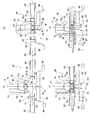
- FIG. 1A to FIG. 1F are partial cross-sectional views showing a method for assembling a cruciform universal joint in the order of steps, showing an example of the first embodiment of the present invention.
- FIG. 2 is an enlarged view of part a in FIG. 1C showing an assembly state before the cup bearing is press-fitted to the reference position.
- FIG. 3 is a diagram schematically showing the relationship between the press-fitting speed of the cup bearing and time.
- FIG. 4 is a diagram showing the relationship between the magnitude of pressure applied to the press-fitting punch and time.
- FIG. 5A to FIG. 5G are partial cross-sectional views showing a method for assembling a cruciform universal joint in the order of steps, showing a first example of the second embodiment of the present invention.
- FIGS. 7A to 7D are partial cross-sectional views showing only the press-fitting step in the method for assembling the cruciform universal joint according to the second example of the second embodiment of the present invention.
- 8 (A) to 8 (D) are partial cross-sectional views showing a method for assembling a cruciform universal joint, showing a first example of the third embodiment of the present invention, in the order of steps.
- 9 (A) to 9 (D) are partial cross-sectional views showing a method of assembling the cruciform universal joint in the order of steps, showing a second example of the third embodiment of the present invention.
- FIG. 10 is a perspective view showing an example of a steering device incorporating a cross shaft type universal joint.
- FIG. 11 is a side view showing an example of a conventional cross shaft type universal joint.
- FIG. 12 is a view as seen from below of FIG.
- FIG. 13A is a cross-sectional view showing a press-fitting process in a conventional method for assembling a cross shaft universal joint
- FIG. 13B is a cross-sectional view showing a caulking process.
- 14 (A) and 14 (B) are partial cross-sectional views for explaining a problem that occurs in the conventional method of assembling a cross shaft type universal joint based on variations in dimensions of members constituting the universal joint.
- FIG. FIGS. 15 (A) to 15 (C) are views for explaining a problem caused by the elastic deformation of the coupling arm portion due to the press-fitting of the bearing cup in the conventional method for assembling the cross shaft universal joint. It is a fragmentary sectional view.
- FIG. 1A to 4 show an example of the first embodiment of the present invention.
- the cross shaft type universal joint that is the object of this example is the same as that of a known one, and a pair of coupling arm portions 10 and a pair of circular holes 15 formed at the distal ends of the pair of coupling arm portions 10.
- a cross shaft 8 having shaft portions 17a and 17b, and a pair of cup bearings 18 for rotatably supporting both end portions of the shaft portion 8 inside the pair of circular holes 15.
- the method of assembling the cross shaft universal joint of this example is also a pair of coupling arms so that at least the distance between the inner side surfaces of the distal end portions of the pair of coupling arm portions 10 can be kept constant, as in the conventional method.
- the cup bearing 18 is made accurate by devising the press-fitting process of the cup bearing 18 regardless of variations in the dimensions of the members constituting the cross shaft universal joint 6 (see FIGS. 10 to 12). The point is that it can be assembled well.
- the structure of other universal joints 6, the structure of the assembling method thereof, and the operation and effects thereof are the same as in the conventional art.
- the assembly method of the universal joint 6 of this example is roughly divided into six steps (A) to (F). Hereinafter, these steps will be described in the order of steps.
- an assembly device 30 including a pair of press-fitting caulking devices 31 and a yoke receiving jig 32 is mainly used as in the conventional method.
- Each of the pair of press-fitting caulking devices 31 includes a columnar press-fitting punch 33, a caulking punch 35 that is substantially cylindrical and is externally fitted to the press-fitting punch 33 so as to be relatively movable, a press-fitting anti 33, and a caulking punch 35.
- a drive mechanism such as a servo motor or a cylinder is provided on each base end side and individually moves.
- the yoke receiving jig 32 includes a pair of substantially L-shaped support arm portions 34 and a drive mechanism such as a servo motor (not shown) for moving each of the pair of support arm portions 34.
- the assembling apparatus 30 includes a controller for controlling a drive mechanism such as a servo motor, a linear scale for measuring the feed amount of the press-fitting punch 33 and the caulking punch, and a device for measuring the pulse amount of these drive mechanisms.
- a controller for controlling a drive mechanism such as a servo motor, a linear scale for measuring the feed amount of the press-fitting punch 33 and the caulking punch, and a device for measuring the pulse amount of these drive mechanisms.
- any known device can be used and is not directly related to the gist of the present invention, the illustration thereof is omitted.
- the center position O (machine center position) in the center axis direction of the circular hole 15 of the pair of support arm portions 34 of the yoke receiving jig 32, which is a support member of the pair of coupling arm portions 10, and
- the yoke 7a is disposed above the yoke receiving jig 32 with the central axis X of the yoke 7a aligned.
- both end portions of the one shaft portion 17 a are positioned coaxially with the central axis of the pair of circular holes 15 of the pair of connecting arm portions 10.
- the tips of the pair of support arm portions 34 are driven.
- the outer side surface of the part is brought into contact with the inner side surface of the distal end part of the pair of connecting arm parts 10.
- the pressure applied to the pair of support arm portions 34 is measured by the pressure sensors respectively installed on the pair of support arm portions 34, and the pressure applied to the pair of support arm portions 34 becomes a predetermined value.
- the pair of connecting arm portions 10 are pressed in the direction of expanding. As a result, the pair of coupling arm portions 10 are backed up in a state where the distance between the inner side surfaces of the tip portions of the pair of coupling arm portions 10 is kept constant.
- a pair of cup bearings 18 is supplied coaxially with the circular hole 15 and the press-fitting punch 33 using a bearing supply device (not shown). However, as shown in FIG. 1A, the pair of cup bearings 18 can be supplied at the stage of the pre-setting process.
- the press-fitting process of the cup bearing 18 is performed in two stages of a high-speed press-fitting process and a medium-speed and low-speed press-fitting process.
- a pair of coupling arm portions 10 are backed up, and one shaft portion from the inner surface side of the pair of coupling arm portions 10 inside a pair of circular holes 15.
- the pair of press-fitting punches 33 are moved forward ( The pair of cup bearings 18 are simultaneously press-fitted into the circular hole 15 from the outer surface side of the pair of coupling arm portions 10.
- the magnitude of the pressure (pressing reaction force) applied to the pair of press-fitting punches 33 is measured by the pressure sensors respectively installed on the pair of press-fitting punches 33, and the number of feed pulses of the linear scale or servo motor
- the feed amount (the press-fit amount of the cup bearing 18) of the pair of press-fit punches 33 with respect to the machine center position O is measured.
- the inner surface of the bottom portion 22 of the cup 19 of the pair of cup bearings 18 is about 0.1 mm to 1.0 mm, preferably 0.
- a position slightly in front of about 3 mm to 0.7 mm is set as a reference position, and the pair of cup bearings 18 is moved by the pair of press-fitting punches 33 until the pair of cup bearings 18 reach the reference position. Press-fit at a high speed (a speed of about 50 mm / second to 100 mm / second).
- the distance between the tip surfaces of the pair of press-fitting punches 33 is such that the axial dimension (including tolerance) of the shaft portion 17a and the gap between the inner surface of the bottom portion 22 and the tip surface of the shaft portion 17a (0
- the pair of press-fitting punches 33 is moved forward at a high speed until it becomes equal to the sum of the double value of about 0.1 mm to about 1.0 mm and the double value of the thickness dimension of the bottom portion 22.
- the bottom part of the cup 19 of the pair of cup bearings 18 is located at a position before the position where both ends of the shaft part 17a are in contact with each other, the amount of press-fitting of the pair of cup bearings 18 is small.
- the initial press-fitting position can also be set as the reference position.
- the bottom portion of the cup 19 approaches to a position where it contacts one of both end portions of the shaft portion 17a. It is preferable to set a position slightly in front of about 0.0 mm as the reference position.
- the press-fitting speed is arbitrarily determined from the viewpoint of the efficiency of press-fitting work according to the performance of the apparatus.
- the value of the pressure applied to the pair of press-fitting punches 33 measured by the pressure sensor is set as a reference pressure (SP) in the controller of the assembly apparatus 30. Store in memory. At this time, the forward movement of the pair of press-fitting punches 33 is temporarily stopped.
- SP reference pressure
- FIG. 2 the position of the tip surface of the press-fitting punch 33 at the time when the cup bearing 18 is press-fitted to the reference position is shown in a state where the distance from the end surface of the shaft portion 17a is wider than that in the actual case. It is represented by a one-dot chain line.
- the pair of cup bearings 18 are further press-fitted by a predetermined amount after the inner surface of the bottom portion 22 abuts against the tip surface of the shaft portion 17a. And preload is applied.
- the press-fitting speed after reaching the reference position of the pair of cup bearings 18 is set to a low speed after being set to a medium speed, and stepwise as the pressure applied to the pair of press-fitting punches 33 increases. To be late.
- the press-fitting speed of the pair of cup bearings 18 may be decreased linearly or curvedly.
- the medium speed and the low press-fitting speed are also arbitrarily determined from the viewpoint of the efficiency of the press-fitting work according to the performance of the apparatus.
- the first predetermined value ( ⁇ ) and the second predetermined value ( ⁇ ) are based on the materials, sizes, shapes, and the like of the yoke 7a, the cup 19 of the cup bearing 18 and the needle 20, and various simulations and experiments. An appropriate value can be obtained in advance.
- the caulking portion 24 is pressed against the outer surface of the bottom portion 22 of the cup 19 to prevent the cup 19 from coming out of the circular hole 15.
- the assembly device 30 is used in which the pair of caulking punches 35 are arranged in a state of being fitted around the pair of press-fitting punches 33, but the pair of press-fitting punches 33 and one pair are used.
- An apparatus provided with the caulking punch 35 individually is also applicable.
- the cup bearing 18 can be assembled with high accuracy.
- SP reference pressure
- the pair of cup bearings 18 is press-fitted until it becomes larger.
- the value of the pressure finally applied to the press-fitting punch 33 (the pressure value determined as the press-fitting completion position) is the dimensional variation that occurs between the inner diameter of the circular hole 15 and the outer diameter of the cup bearing 18. It is determined in consideration of the value of the reference pressure (SP) that changes due to the above. For this reason, the influence of this variation on the press-fitting amount (press-fit position) of the cup bearing 18 can be eliminated.
- the reference pressure (SP1) is larger than the inner diameter dimension of the circular hole 15. Yes, it becomes larger than the reference pressure (SP2) when the outer diameter of the cup bearing 18 is smaller (SP1> SP2).
- the press-fitting amount of the cup bearing 18 is determined based only on the magnitude of the pressure applied to the press-fitting punch 33, the inner diameter dimension of the circular hole 15 is smaller and the outer diameter dimension of the cup bearing 18 is larger.
- the press-fit amount of the cup bearing 18 may be excessive.
- the press-fit completion position is not determined based on the press-fit amount of the pair of cup bearings 18, but the position where the pressure has increased by a second predetermined value ( ⁇ ) set in advance from the reference pressure (SP1, SP2). Is determined to be a press-fit completion position where an appropriate preload can be applied to the pair of cup bearings 18. For this reason, the influence which the dispersion
- the pair of cup bearings 18 are assembled with high accuracy at an appropriate position where an appropriate preload can be applied regardless of variations in dimensions of the members constituting the universal joint 6. be able to.
- the press-fitting operation cycle Time can be shortened.
- the press-fitting speed of the pair of cup bearings 18 is not reduced from a high speed to a low speed at once, but a pair of press-fitting punches 33. Since the applied pressure is delayed in steps according to the amount of increase from the reference pressure, the press-fitting speed can be secured to some extent even in the middle stage, and the cycle time can be further shortened.
- the press-fitting operation of the pair of cup bearings 18 is performed simultaneously from the viewpoint of work efficiency. However, it is also possible to sequentially perform each process for each of the pair of cup bearings 18. Such cases are also included in the scope of the present invention.
- the assembly method of the cross shaft type universal joint 6 of this example is roughly divided into seven steps (A) to (G). Among these processes, (A) the pre-setting process, (B) the backup process, (G) the caulking process, and the taking-out process are all the same as one example of the first embodiment. For this reason, description of these steps is omitted.
- the first press-fitting process shown in FIG. 5C is substantially the same as the high-speed press-fitting process in the example of the first embodiment shown in FIG.
- the press-fitting sensor is installed only on the right press-fitting punch 33b in FIG. 5C among the pair of press-fitting punches 33a and 33b.
- the feed amount with respect to the machine center position O of the pair of press-fitting punches 33a and 33b is measured by the number of feed pulses of the linear scale or the servo motor.
- the reference position where the pair of cup bearings 18a and 18b is set in advance for example, the inner surfaces of the bottom portions 22a and 22b of the cups 19a and 19b of the pair of cup bearings 18a and 18b is one shaft portion 17a of the cross shaft 8.
- the pressure value applied to the press-fitting punch 33b measured by the pressure sensor at the time of press-fitting to a position about 0.1 mm to 1.0 mm before the position in contact with the tip surface of the head is defined as a reference pressure (SP).
- SP reference pressure
- the data is stored in a memory in the controller of the assembling apparatus 30.
- one cup bearing 18a is press-fitted to a preset press-fitting completion position by positioning control.
- the other cup bearing 18b (the right side in FIG. 5D) of the pair of cup bearings 18a and 18b is kept stopped at the reference position.
- the other press-fitting punch 33b of the pair of cup bearings 18a and 18b is also stopped in a state in which the tip end surface thereof is in contact with the outer surface of the bottom portion 22b of the cup 19b of the other cup bearing 18b.
- the press-fitting speed from the reference position of one cup bearing 18a to the press-fitting completion position is set lower than the press-fitting speed from the start position to the reference position.
- the medium cup speed (about 1/2500 to 1/500 of the speed at the time of high speed) in which the press-fitting speed of the other cup bearing 18b is set lower than that of the first press-fitting process. Speed), the press-fitting operation of the other cup bearing 18b is resumed.
- the other cup bearing 18b is pushed into the inner side of the circular hole 15b, and at the same time, the cross shaft 8 is pushed in the axial direction of the shaft portion 17a toward the one cup bearing 18a via the other cup bearing 18b. . Then, the gap formed between the inner surface of the bottom portion 22a of the cup 19a of one cup bearing 18a and the tip surface of one end of the shaft portion 17a is gradually reduced, and finally this Set the gap to zero.
- the value of the pressure applied to the other press-fitting punch 33b is the first predetermined value ( ⁇ ) set in advance from the reference pressure (SP).
- ⁇ the press-fitting speed of the other cup bearing 18b
- the other cup bearing 18b and the cross shaft 8 are pushed to a position as shown in FIG. 6A, and the pressure value applied to the other press-fitting punch 33b is preliminarily higher than the reference pressure (SP).
- SP reference pressure
- the press-fitting speed after the other cup bearing 18b reaches the reference position is set to a low speed after being set to a medium speed, and stepwise as the pressure applied to the other press-fitting punch 33b increases.
- the press-fitting speed is slow.
- the press-fitting speed of the other cup bearing 18b can be decreased continuously (linearly or curvilinearly).
- the first predetermined value ( ⁇ ) and the second predetermined value ( ⁇ ) are based on the material, size, shape, etc. of the yoke 7a and the cup bearings 18a, 18b (cups 19a, 19b, needle 20). An appropriate value is obtained in advance by simulation or experiment.
- the second predetermined value ( ⁇ ) is greater than the value that can give an appropriate preload to the other cup bearing 18b when it is assumed that the other coupling arm 10b is not bent and deformed. It is preferable to set a larger value by the preload loss due to the release of the bending deformation of 10b.
- the circular holes 15a and 15b formed at the front ends of the pair of coupling arm portions 10a and 10b and the cross are formed regardless of the bending deformation of the pair of coupling arm portions 10a and 10b of the yoke 7a.
- a pair of cup bearings 18a and 18b can be assembled with high accuracy at a portion between both end portions of the shaft portion 17a of the shaft 8.
- one cup produced by releasing the bending deformation of one coupling arm portion 10a after releasing the bending deformation of one coupling arm portion 10a out of the pair of coupling arm portions 10a and 10b, one cup produced by releasing the bending deformation of one coupling arm portion 10a.
- the other cup bearing 18b is cross-shaped using the other press-fitting punch 33b so as to eliminate a gap between the inner surface of the bottom 22a of the cup 19a of the bearing 18a and the tip surface of one end of the shaft portion 17a. Push the shaft 8 together.
- the inner surfaces of the bottom portions 22a and 22b of the cups 19a and 19b of the pair of cup bearings 18a and 18b are connected to both ends of the shaft portion 17a.
- the total amount of movement moving in the direction away from the surface can be suppressed to the amount of bending deformation of the other connecting arm portion 10b. Therefore, as shown in FIG. 15, the amount of movement can be reduced to about half compared to the case of moving by the total amount of bending deformation of the pair of coupling arm portions 10.
- the movement amount based only on the bending deformation of the other coupling arm portion 10b is small, the movement amount can be absorbed within the range of the preload by the elastic deformation of the bottom portions 22a and 22b of the cups 19a and 19b.
- the second predetermined value ( ⁇ ) is set so that no bending deformation occurs in the other coupling arm portion 10b, the coupling of the other is more than a value that can give an appropriate preload to the other cup bearing 18b.
- the preload loss due to the release of the bending deformation of the arm portion 10b is set to a large value.
- the pair of cup bearings 18a and 18b can be assembled with high accuracy at an appropriate position where an appropriate preload can be applied.
- the pair of cup bearings 18a and 18b can be assembled with high accuracy at an appropriate position where an appropriate preload can be applied, regardless of variations in dimensions of the members constituting the cross shaft universal joint 6. That is, when the other cup bearing 18b is press-fitted to the reference position, the second predetermined value (the pressure value is set in advance with reference to the reference pressure (SP), which is the value of the pressure applied to the other press-fitting punch 33b). The other cup bearing 18b is press-fitted until it becomes larger by ⁇ ).
- SP reference pressure
- the value of the pressure finally applied to the other press-fitting punch 33b (the value of the pressure determined to be the press-fitting completion position) is set to the inner diameter dimension of the circular hole 15b and the outer diameter dimension of the other cup bearing 18b. Since the determination is made in consideration of the value of the reference pressure (SP) that changes due to the dimensional variation occurring in the meantime, the influence of this variation on the press-fitting amount (press-fit position) of the other cup bearing 18b can be eliminated.
- SP reference pressure
- FIG. 7 shows a second example of the second embodiment of the present invention. This example is different from the first example of the second embodiment only in the press-fitting process, and the other processes and the assembly apparatus 30 to be used are basically the same.
- the inner surfaces of the bottom portions 22a and 22b of the cups 19a and 19b of the pair of cup bearings 18a and 18b are 0.1 mm to 1.0 mm from the position where the inner surfaces of the shaft portions 17a of the cross shaft 8 are in contact with each other.
- the pair of cup bearings 18a and 18b is press-fitted at a high speed until reaching a position just before, and the value of the pressure applied to the press-fitting punch 33b measured by the pressure sensor at this time is a reference pressure (SP). Not handled.
- SP reference pressure
- the other press-fitting punch 33b is inserted into the other press-fitting punch 33b at a medium speed (a speed about 1/2500 to 1/500 of the speed at the high speed) at which the press-fitting speed of the other cup bearing 18b is set lower than that of the first press-fitting process. While monitoring the applied pressure and the press-fitting position, the press-fitting operation of the other cup bearing 18b is resumed, the other cup bearing 18b is pushed into the back side of the circular hole 15b, and the cross shaft 8 is inserted via the other cup bearing 18b.
- a medium speed a speed about 1/2500 to 1/500 of the speed at the high speed
- the pressure value at this inflection point is set as the reference pressure (SP). Then, when the value of the pressure applied to the other press-fitting punch 33b becomes larger than the reference pressure (SP) by a predetermined value ( ⁇ ), the other cup bearing 18b reaches the press-fitting completion position. It is determined that Next, the other press-fitting punch 33b is retracted until it separates from the outer surface of the bottom 22b of the cup 19b of the other cup bearing 18b, and the press-fitting operation is completed. Further, by retracting the other press-fitting punch 33b, the bending deformation generated in the other coupling arm portion 10b (the right side in FIG.
- the predetermined value ( ⁇ ) is determined in advance by various simulations and experiments based on the material, size, shape, etc. of the yoke 7a and the pair of cup bearings 18a, 18b (cups 19a, 19b, needle 20). Find the value.
- the predetermined value ( ⁇ ) is a deflection of the other coupling arm portion 10b than a value at which an appropriate preload can be applied to the other cup bearing 18b when the other coupling arm portion 10b is not bent and deformed. It is preferable to make the value larger by the amount of preload loss due to release of deformation.
- the pair of cup bearings 18a and 18b can be assembled with high accuracy at a portion between both end portions of the shaft portion 17a.
- the pair of cup bearings 18a and 18b can be assembled with high accuracy at an appropriate position where an appropriate preload can be applied, regardless of variations in the dimensions of the members constituting the universal joint 6. That is, in this example, the pressure value at the inflection point that represents the point in time when the tip surface of the shaft portion 17a of the cross shaft 8 starts to contact the inner surface of the bottom portion 22a of the cup 19a of the one cup bearing 18a, The other cup bearing 18b is press-fit until the pressure (SP) increases by a preset value ( ⁇ ).
- the pressure value finally applied to the other press-fitting punch 33b (the pressure value to be determined as the press-fitting completion position) is set to the inner diameter dimension of the circular holes 15a and 15b and the outer diameter dimension of the cup bearings 18a and 18b. Since the determination is made based on the pressure value at the inflection point that is not affected by the dimensional variation that occurs between them, the influence of this variation on the press-fitting amount (press-fit position) of the other cup bearing 18b can be eliminated.
- the press-fit completion position is not determined based on the press-fit amount of the cup bearing 18b, but the position where the pressure has increased by a preset value ( ⁇ ) from the reference pressure (SP) is set to the other cup bearing 18b.
- the pair of cup bearings 18a and 18b can be assembled with high accuracy at an appropriate position where an appropriate preload can be applied, regardless of variations in the dimensions of the constituent members of the universal joint 6. .
- the pair of cup bearings 18a and 18b can be assembled with high accuracy at an appropriate position where an appropriate preload can be applied, regardless of variations in the dimensions of the constituent members of the universal joint 6. .
- it is the same as that of the case of the 1st example of 2nd Embodiment.
- FIG. 8A to 8D show a first example of the third embodiment of the present invention.
- the feature of this example is that the yoke 7a backup process is devised among the pre-set process, backup process, press-fitting process, caulking process, and take-out process that constitute the assembly method of the cross shaft type universal joint 6.
- the cup bearing 18 is assembled with high accuracy regardless of variations in the inner surface dimensions of the pair of connecting arm portions 10 of the yoke 7a (distances from the yoke central axis X to the respective inner surfaces of the pair of connecting arm portions 10). Is that it can be done.
- the structure of other universal joints 6, the structure of the assembling method thereof, and the operation and effects thereof are the same as in the conventional art. Moreover, since the description about these is the same as that of one example of 1st Embodiment, it simplifies or abbreviate
- both end portions of one shaft portion 17a of the cross shaft 8 are respectively inserted into the circular holes 15 formed in the pair of connecting arm portions 10 of the yoke 7a.
- the yoke 7a is placed above the yoke receiving jig 32, and the circular holes 15 of the pair of supporting arm parts 34 of the yoke receiving jig 32, which are supporting members of the pair of connecting arm parts 10.
- the center position O (machine center position) in the direction of the center axis and the center axis X of the yoke 7a are made to coincide with each other and held downward by a chuck (not shown).
- the pair of support arm portions 34 are moved away from the machine center position O, and the distal end portion outer surfaces of the pair of support arm portions 34 are moved to a pair.
- the connecting arm portion 10 is brought into contact with the inner surface of the distal end portion.
- the movement speed of the pair of support arm portions 34 and the timing of the start of movement are shifted so that the operations of the pair of support arm portions 34 do not completely match (not synchronized with each other).
- the pair of support arm portions 34 are held until a predetermined torque equal to each other set in advance in the servo motor 36, that is, a torque capable of applying a pressing force enough to back up the pair of coupled arm portions 10 is generated.
- the yoke 7a is held by a chuck so that at least the circular hole 15 can be translated in the central axis direction, or support by the pair of support arm portions 34 is started. At this point, the holding of the yoke 7a by the chuck is released. As a result, as shown in FIG. 8B, the yoke 7 a moves in parallel so as to shift in the direction of the central axis of the circular hole 15 with the movement of the pair of support arm portions 34. In addition, in this deviation
- the center position (the center position between the outer surfaces of the tip end portions) P of the pair of support arm portions 34 is obtained.
- the controller of the assembling apparatus 30 that controls the servo motors 36 uses the number of pulses of the servo motors 36 to make one pair.
- the center position P of the pair of support arm portions 34 can be obtained by calculating the feed amount of each support arm portion 34 (the amount of movement from the machine center position O).
- the deviation amount ( ⁇ ) of the center position P from the machine center position O is obtained.
- a pair of cup bearings 18 is supplied coaxially with the circular hole 15 and the press-fitting punch 33 using a bearing supply device (not shown).
- the pair of cup bearings 18 can be supplied at the stage of the pre-setting process and kept on standby.
- the command position (press-fit completion position set on the assumption that no deviation has occurred) Y1 is set to move to a position (corrected press-fit command position Y1 ′) to which ⁇ is added, on the contrary, FIG.
- the right end of the press-fitting punch 33 is set so as to move from the normal press-fitting command position Y2 to a position obtained by subtracting ⁇ (corrected press-fitting command position Y2 ′). Then, the pair of press-fitting punches 33 are moved to the respective corrected press-fitting command positions (Y1 ′, Y2 ′), and the press-fitting operation is completed.
- the pair of caulking punches 35 are moved forward.
- the feeding amount (forward movement amount) of the pair of caulking punches 35 is corrected according to the deviation amount ( ⁇ ). Specifically, since the center position P of the pair of support arm portions 34 at the time when the backup process is completed is shifted to the right side by ⁇ from the machine center position O, the caulking on the left side in FIG.
- the position of the front end surface of the punch 35 is moved to a position (corrected caulking command position Z1 ′) obtained by adding ⁇ to a normal caulking command position (caulking completion position set assuming that there is no deviation) Z1.
- the position of the front end surface of the caulking punch 35 on the right side in FIG. 8D is set to move to the position (corrected caulking command position Z2 ′) obtained by subtracting ⁇ from the normal caulking command Z2. ing. Then, the front end surfaces of the pair of caulking punches 35 are moved to the respective corrected caulking command positions (Z1 ′, Z2 ′), and the inner peripheral edge of the circular hole 15 is moved by the front end surfaces of the pair of caulking punches 35. A plurality of portions in the circumferential direction of the portion are plastically deformed. And the caulking part 24 (refer FIG. 11 and FIG. 12) is formed in the said part. Accordingly, the caulking portion 24 is pressed against the outer surface of the bottom portion 22 of the cup 19 to prevent the cup 19 from coming out of the circular hole 15.
- the pair of caulking punches 35 and the pair of press-fitting punches 33 are retracted to their initial positions, and the pair of support arm portions 34 of the yoke receiving jig 32 are moved toward each other. Then, the backup of the pair of coupled arm portions 10 by the pair of support arm portions 34 is released, and the yoke 7a is retracted to the position above the yoke receiving jig 32, whereby the yoke 7a is removed from the assembly apparatus 30. Take out.
- a pair of cup bearings 18 can be assembled to a certain portion with high accuracy.
- a pair of coupled arm portions are moved from the machine center position O of the pair of support arm portions 34 using the number of pulses of each servo motor 36 that moves the pair of support arm portions 34.
- the amount of deviation ( ⁇ ) to the center position P of the pair of support arm portions 34 in the state where the pair of support arms 34 is supported is obtained, and the front of the pair of press-fitting punches 33 and the pair of caulking punches 35 based on the amount of deviation.
- the amount of movement to each is corrected.
- the pair of cup bearings 18 can be assembled with high accuracy at an appropriate position where an appropriate preload can be applied, and the amount of caulking of the caulking portion 24 can be achieved. Insufficient (plastic deformation amount) can be prevented, and the pair of cup bearings 18 can be sufficiently prevented from coming off.
- the pair of support arm portions 34 are moved until a predetermined torque is generated in the servo motor 36 to support the pair of joint arm portions 10, variations in the inner surface dimensions of the pair of joint arm portions 10. Regardless, the pair of coupling arms 10 can be supported with an appropriate force.
- FIG. 9A shows a second example of the third embodiment of the present invention.
- the feature of this example is that the variation in the axial dimension of the shaft portion 17a of the cross shaft 8 and the variation in the thickness dimension of the bottom portion 22 of the cup 19 of the cup bearing 18 are the front of the press-fitting punch 33 and the caulking punch 35. It is in the point which eliminates the influence which it has on the movement amount to. Other processes and effects are the same as in the first example of the third embodiment.
- the pair of press-fitting punches 33 are moved forward to connect the pair of cup bearings 18 to a pair of couplings.
- the feed amount of the pair of press-fitting punches 33 is changed from the machine center position O of the pair of support arm portions 34 to a pair of coupled arm portions. 10 is corrected according to the amount of deviation ( ⁇ ) to the center position P of the pair of support arm portions 34 in a state where 10 is supported.
- the magnitude of the pressure (pressing reaction force) applied to the pair of press-fitting punches 33 is measured by pressure sensors respectively installed on the pair of press-fitting punches 33. That is, the pair of press-fitting punches 33 are corrected to the corrected press-fitting command position (Y1) due to variations in the axial dimension of the shaft part 17a of the cross shaft 8 and the thickness dimension of the bottom part 22 of the cup 19 within the dimensional tolerance. ′, Y2 ′) before reaching the pair of cup bearings 18, even when a proper preload is applied to the pair of cup bearings 18 or when the corrected press-fitting command positions (Y1 ′, Y2 ′) are reached.
- the preload is insufficient without a proper preload being applied. Therefore, in this example, even if the feed amount of the pair of press-fitting punches 33 has not reached the corrected press-fitting command position (Y1 ′, Y2 ′), the value of the pressure applied to the pair of press-fitting punches 33 is set in advance. When the predetermined value is reached, the press-fitting operation is terminated. Then, the difference ( ⁇ ) between the position where the press-fitting by the pair of press-fitting punches 33 is actually completed and the corrected press-fitting command position (Y1 ′, Y2 ′) is obtained.
- the feed amount of the pair of caulking punches 35 is corrected according to the two shift amounts of ⁇ and ⁇ . Specifically, since the center position P of the pair of support arm portions 34 is shifted to the right side by ⁇ from the machine center position O, the position of the front end surface of the caulking punch 35 on the left side in FIG. Set to move to the first correction caulking command position (Z1 ′) obtained by adding ⁇ to the normal caulking command position Z1 to the position (second correction caulking command position Z1 ′ ⁇ ⁇ ) further increased or decreased by ⁇ . The position of the front end surface of the caulking punch 35 on the right side of FIG.
- the axial dimension of the shaft portion 17a of the cross shaft 8 and the variation in the thickness dimension of the bottom portion 22 of the cup 19 are the amounts of forward movement of the pair of press-fitting punches 33 and the pair of caulking punches 35. It is possible to eliminate the influence. Therefore, an appropriate preload can be applied to the pair of cup bearings 18 regardless of variations in the axial dimension of the shaft part 17a of the cross shaft 8 and the thickness dimension of the bottom part 22 of the cup 19, and the caulking part 24 can be applied. The amount of caulking can be secured appropriately. Therefore, the pair of cup bearings 18 can be assembled with high accuracy.
- the present invention is not limited to one example of the first embodiment, the first and second examples of the second embodiment, and the first and second examples of the third embodiment. These embodiments can be combined with each other as long as they do not contradict each other, and such embodiments are also included in the present invention.
- the assembly method of the present invention is not limited to the cross shaft universal joint incorporated in the steering device, but can be widely applied to a cross shaft universal joint assembled to a propeller shaft or various torque transmission mechanisms.
Landscapes
- Engineering & Computer Science (AREA)
- General Engineering & Computer Science (AREA)
- Mechanical Engineering (AREA)
- Automatic Assembly (AREA)
Abstract
Description
図1(A)~図4は、本発明の第1の実施形態の1例を示している。本例の対象となる十字軸式自在継手は公知のものと同様であり、1対の結合腕部10と、1対の結合腕部10の先端部に形成された1対の円孔15とを備えたヨーク7aと、軸部17a、17bを備えた十字軸8と、軸部8の両端部を1対の円孔15の内側に回転自在に支持するための1対のカップ軸受18とを備える。本例の十字軸式自在継手の組立方法も、従来の方法と同様に、少なくとも、1対の結合腕部10の先端部の内側面同士の間隔を一定に保持できるように1対の結合腕部10をバックアップする工程と、1対の結合腕部10をバックアップした状態で、1対の結合腕部10の1対の円孔15と、1対の円孔15の内側に1対の結合腕部10の内側面側から挿入された軸部17a、17bの両端部との間にある部分に、1対のカップ軸受18を1対の結合腕部10の外側面側から1対の圧入パンチ33を用いて圧入する工程とを備える。
図1(A)に示すように、十字軸8の一方の軸部17aの両端部を、ヨーク7aの1対の結合腕部10に形成された円孔15内にそれぞれ挿入した予備組み立て状態で、ヨーク7aを、ヨーク受け治具32の上方位置に、図示しないチャックにより下向きに保持する。より具体的には、1対の結合腕部10の支持部材である、ヨーク受け治具32の1対の支持腕部34の円孔15の中心軸方向の中心位置O(機械中心位置)と、ヨーク7aの中心軸Xとを一致させた状態で、ヨーク7aをヨーク受け治具32の上方位置に配置する。また、図示しないセンタ出し治具を用いて、一方の軸部17aの両端部を、1対の結合腕部10の1対の円孔15の中心軸と同軸上に位置させる。
次に、図1(B)に示すように、ヨーク7aを所定量だけ下降させて、1対の結合腕部10の円孔15と、1対の圧入かしめ装置31の1対の圧入パンチ33とを同軸上に位置させる。また、この状態で、1対の結合腕部10の先端部の内側面同士の間に、ヨーク受け治具32の1対の支持腕部34の先端部を挿入する。次いで、ヨーク受け治具32のサーボモータを駆動することにより、1対の支持腕部34を互いに離れる方向(図1(B)の左右方向)に駆動し、1対の支持腕部34の先端部外側面を、1対の結合腕部10の先端部内側面に当接させる。そして、1対の支持腕部34にそれぞれ設置した圧力センサにより、1対の支持腕部34に加わる圧力の大きさを測定して、1対の支持腕部34に加わる圧力が所定値になるまで、1対の結合腕部10を拡開する方向に押圧する。これにより、1対の結合腕部10の先端部の内側面同士の間隔が一定に保持された状態で、1対の結合腕部10がバックアップされる。次に、図示しない軸受供給装置を利用して、1対のカップ軸受18を、円孔15および圧入パンチ33と同軸上に供給する。ただし、1対のカップ軸受18は、図1(A)に示したように、セット前工程の段階で供給することもできる。
本例では、カップ軸受18の圧入工程を、高速圧入工程と、中速および低速圧入工程との2段階で行うことを特徴とする。まず、図1(C)に示すように、1対の結合腕部10がバックアップされ、かつ、1対の円孔15の内側に1対の結合腕部10の内側面側から一方の軸部17aが挿入された状態で、1対の圧入かしめ装置31のサーボモータを駆動することにより、または、油圧もしくは空圧によって作動するシリンダを駆動することにより、1対の圧入パンチ33をそれぞれ前方(互いに近づく方向)に移動させて、1対のカップ軸受18を、1対の結合腕部10の外側面側から円孔15内に同時に圧入する。本例では、1対の圧入パンチ33にそれぞれ設置した圧力センサにより、1対の圧入パンチ33に加わる圧力(圧入反力)の大きさを測定し、かつ、リニアスケールまたはサーボモータの送りパルス数により、1対の圧入パンチ33の機械中心位置Oに対する送り量(カップ軸受18の圧入量)を測定している。これにより、1対のカップ軸受18のカップ19の底部22の内面が、軸部17aの両端部のそれぞれの先端面に当接する位置よりも0.1mm~1.0mm程度、好ましくは、0.3mm~0.7mm程度という、わずかに手前の位置を基準位置として定め、1対のカップ軸受18がこの基準位置にそれぞれ到達するまで、1対の圧入パンチ33によりこれら1対のカップ軸受18を高速(50mm/秒~100mm/秒程度の速度)で圧入する。
次に、図1(D)および図3に示すように、1対のカップ軸受18の圧入速度をこれまでよりも低く設定した中速(高速時の速度の1/2500~1/500程度の速度=0.02mm/秒~0.2mm/秒程度の速度)にて、圧入を再開する。そして、図4に示すように、1対の圧入パンチ33に加わる圧力の値が、基準圧力(SP)よりも予め設定した第一の所定値(α)分だけ大きくなった時点で、1対のカップ軸受18の圧入速度を、中速から低速(中速時の速度の半分程度の速度=0.01mm/秒~0.1mm/秒程度の速度)に減速して圧入を継続する。そして、最終的に、1対の圧入パンチ33に加わる圧力の値が、基準圧力(SP)よりも予め設定した第二の所定値(β、β>α)分だけ大きくなった時点で、1対のカップ軸受18が圧入完了位置にまで達したと判定して圧入作業を終了する。
次いで、図1(E)に示すように、1対の圧入かしめ装置31のサーボモータ(圧入パンチ33の駆動に用いるサーボモータとは別のサーボモータ)を駆動することにより、または、油圧もしくは空圧によって作動するシリンダを駆動することにより、1対のかしめパンチ35を前方に移動させる。そして、1対のかしめパンチ35の先端面により、1対の結合腕部10の外側面のうち、円孔15の開口縁部の円周方向複数個所を塑性変形させて、当該部分にかしめ部24(図11および図12参照)を形成する。これにより、かしめ部24を、カップ19の底部22の外面に押し付けて、カップ19が円孔15から抜け出ることを防止する。なお、本例では、1対の圧入パンチ33の周囲に外嵌した状態で1対のかしめパンチ35が配置されている組立装置30を使用しているが、1対の圧入パンチ33と1対のかしめパンチ35を個別に備える装置も適用可能である。
最後に、図1(F)に示すように、1対のかしめパンチ35および1対の圧入パンチ33を、それぞれ初期位置まで後退させる。また、ヨーク受け治具32の1対の支持腕部34同士を、互いに近づく方向に移動させて、これら1対の支持腕部34による1対の結合腕部10のバックアップを解除する。次いで、ヨーク7aを、ヨーク受け治具32の上方位置に退避させて、ヨーク7aを組立装置30から取り出す。
図5(A)~図5(G)、図6(A)および図6(B)は、本発明の第2実施形態の第1例を示している。なお、本例の特徴は、1対のカップ軸受18a、18bの圧入工程を工夫することにより、ヨーク7aの1対の結合腕部10a、10bの撓み変形にかかわらず、1対のカップ軸受18a、18bを精度よく組み付けられる組立方法を実現する点にある。その他の構成および作用効果については、第1実施形態の1例と同様である。
図5(C)に示した圧入第一工程も、図1(C)に示した第1実施形態の1例における高速圧入工程とほぼ同様である。ただし、本例では、1対の圧入パンチ33a、33bのうち、図5(C)における右側の圧入パンチ33bにのみ圧入センサを設置している。本例の圧入第一工程においても、リニアスケールまたはサーボモータの送りパルス数により、1対の圧入パンチ33a、33bの機械中心位置Oに対する送り量(カップ軸受18a、18bの圧入量)を測定して、1対のカップ軸受18a、18bを予め設定した基準位置、たとえば、1対のカップ軸受18a、18bのカップ19a、19bの底部22a、22bの内面が、十字軸8の一方の軸部17aの先端面に当接する位置よりも0.1mm~1.0mm程度手前の位置にまで圧入した時点で、圧力センサにより測定される圧入パンチ33bに加わる圧力の値を、基準圧力(SP)として、組立装置30の制御器中のメモリに記憶するようにしている。ところで、このような圧入第一工程において、1対のカップ軸受18a、18bをそれぞれ圧入するのに伴って、1対の結合腕部10a、10bに、1対の円孔15a、15bの周囲部分同士を互いに近づける方向の撓み変形が生じる場合がある。
圧入第一工程において、1対の軸受カップ18a、18bを基準位置まで圧入したならば、図5(D)に示すように、圧入第二工程として、これら1対のカップ軸受18a、18bのうちの一方(図5(D)の左側)のカップ軸受18aのみを、圧入完了位置まで圧入する。本例では、1対の圧入パンチ33a、33bのうち、一方のカップ軸受18aを押圧する一方の圧入パンチ33aの送り量(機械中心位置に対する移動量)をリニアスケールまたはサーボモータの送りパルス数により監視しつつ、位置決め制御により、一方のカップ軸受18aを予め設定した圧入完了位置まで圧入する。これに対し、1対のカップ軸受18a、18bのうちの他方(図5(D)の右側)のカップ軸受18bは、基準位置で停止したままにしておく。また、1対のカップ軸受18a、18bのうちの他方の圧入パンチ33bに関しても、その先端面を、他方のカップ軸受18bのカップ19bの底部22bの外面に当接させた状態で停止させておく。なお、一方のカップ軸受18aの基準位置から圧入完了位置までの圧入速度は、開始位置から基準位置までの圧入速度に比べて低く設定される。
次いで、図5(E)に示すように、圧入第三工程として、一方の圧入パンチ33aのみを、一方のカップ軸受18aのカップ19aの底部22aの外面から所定量(2mm以上、好ましくは4mm以上)離れるまで、後退させる。これにより、1対の結合腕部10a、10bに、1対の円孔15a、15bの周囲部分同士を互いに近づける方向の撓み変形が生じている場合でも、一方のカップ軸受18aを組み込んだ一方(図5(E)の左側)の結合腕部10aに生じた撓み変形が解放される。これにより、一方のカップ軸受18aのカップ19aの底部22aの内面と、一方の軸部17aの両端部のうちの一方の先端面との間には、一方の結合腕部10aの撓み変形を解放したことに起因する隙間が形成される。
そして、図5(F)に示すように、圧入第四工程として、他方の圧入パンチ33bに加わる圧力の値が、基準圧力(SP)よりも予め設定した第一の所定値(α)分だけ大きくなった時点で、他方のカップ軸受18bの圧入速度を、中速から低速(中速時の速度の半分程度の速度)に減速して圧入を継続する。そして、最終的に、図6(A)に示すような位置まで、他方のカップ軸受18bおよび十字軸8を押し込み、他方の圧入パンチ33bに加わる圧力の値が、基準圧力(SP)よりも予め設定した第二の所定値(β、β>α)分だけ大きくなった時点で、他方のカップ軸受18bが圧入完了位置にまで達したと判定する。
図7は、本発明の第2実施形態の第2例を示している。本例は、第2実施形態の第1例と、圧入工程のみが相違し、その他の工程、および、使用する組立装置30については、基本的には同じである。
本例でも、(A)セット前工程、および、(B)バックアップ工程が完了したならば、図7(A)に示すように、第1実施形態の1例における高速圧入工程および第2実施形態の第1例における圧入第一工程とほぼ同様に、圧入第一工程を実施する。本例でも、図7(A)の右側の圧入パンチ33bに設置した圧力センサにより、圧入パンチ33bに加わる圧力の大きさを測定するが、1対のカップ軸受18a、18bが予め設定した基準位置、たとえば、1対のカップ軸受18a、18bのカップ19a、19bの底部22a、22bの内面が、十字軸8の一方の軸部17aの先端面に当接する位置よりも0.1mm~1.0mm程度手前の位置に到達するまで、1対のカップ軸受18a、18bを高速で圧入するが、この時点における、圧力センサにより測定される圧入パンチ33bに加わる圧力の値は、基準圧力(SP)として取り扱われない。
その後、図7(B)に示すように、圧入第二工程として、第2実施形態の第1例と同様に、1対のカップ軸受18a、18bのうちの一方(図7(B)の左側)のカップ軸受18aのみを、圧入完了位置まで圧入する。
次いで、図7(C)に示すように、圧入第三工程として、第2実施形態の第1例と同様に、一方の圧入パンチ33aのみを、一方のカップ軸受18aのカップ19aの底部22aの外面から所定量(たとえば、2mm以上、好ましくは4mm以上)離れるまで、後退させて、一方の結合腕部10a、10bに撓み変形が生じている場合でも、一方のカップ軸受18aを組み込んだ一方(図7(C)の左側)の結合腕部10aに生じた撓み変形を解放する。これにより、一方のカップ軸受18aのカップ19aの底部22aの内面と、軸部17aのうちの一方の端部の先端面との間に、隙間が形成される。
本例では、図7(D)に示すように、圧入第四工程として、他方の軸受カップ18bの圧入量(圧入位置)が、予め設定した所定の位置に達した時点で、他方のカップ軸受18bの圧入速度を、中速から低速(中速時の半分程度の速度)に減速して圧入を継続する。そして、他方の圧入パンチ33bに加わる圧力の値を監視している中で、軸部17aの一方の端部の先端面が一方のカップ軸受18aのカップ19aの底部22aの内面に当接し始めたことを表す変曲点(圧力の値が増加傾向に変化する点)を検出したならば、この変曲点での圧力の値を基準圧力(SP)として設定する。そして、他方の圧入パンチ33bに加わる圧力の値が、この基準圧力(SP)よりも予め設定した所定値(γ)分だけ大きくなった時点で、他方のカップ軸受18bが圧入完了位置にまで達したと判定する。次いで、他方の圧入パンチ33bを、他方のカップ軸受18bのカップ19bの底部22bの外面から離れるまで後退させて、圧入作業を終了する。また、他方の圧入パンチ33bを後退させることにより、他方のカップ軸受18bを組み込んだ他方(図12の右側)の結合腕部10bに生じた撓み変形が解放される。なお、他方のカップ軸受18bの基準位置到達後の圧入速度を、連続的(直線的または曲線的)に遅くすることもできる。また、前記所定値(γ)は、ヨーク7aや1対のカップ軸受18a、18b(カップ19a、19b、ニードル20)の材質、大きさ、形状などに基づき、各種シミュレーションや実験などにより予め適正な値を求めておく。特に、所定値(γ)は、他方の結合腕部10bに撓み変形が生じないとした場合に、他方のカップ軸受18bに適正な予圧を付与できる値よりも、他方の結合腕部10bの撓み変形の解放による予圧抜け分だけ大きな値とすることが好ましい。
図8(A)~(D)は、本発明の第3実施形態の第1例を示している。なお、本例の特徴は、十字軸式自在継手6の組立方法を構成する、セット前工程、バックアップ工程、圧入工程、かしめ工程、および取り出し工程のうち、ヨーク7aのバックアップ工程を工夫することにより、ヨーク7aの1対の結合腕部10の内側面寸法(ヨーク中心軸Xから1対の結合腕部10のそれぞれの内側面までの距離)のばらつきにかかわらず、カップ軸受18を精度よく組み付けられることを可能とする点にある。その他の自在継手6の構造およびその組立方法の構成およびこれらの作用効果については、従来と同様である。また、これらについての説明は、第1実施形態の1例と同様であるから、以下の説明においては、簡略化または省略する。
図8(A)に示すように、セット前工程として、十字軸8の一方の軸部17aの両端部を、ヨーク7aの1対の結合腕部10に形成された円孔15内にそれぞれ挿入した予備組み立て状態で、ヨーク7aを、ヨーク受け治具32の上方位置に、1対の結合腕部10の支持部材である、ヨーク受け治具32の1対の支持腕部34の円孔15の中心軸方向の中心位置O(機械中心位置)と、ヨーク7aの中心軸Xとを一致させるよういして、図示しないチャックにより下向きに保持する。
次に、図8(B)に示すように、バックアップ工程として、ヨーク7aを所定量だけ下降させて、1対の結合腕部10の先端部に形成された円孔15と、1対の圧入パンチ33とかしめパンチ35とを同軸上に位置させる。また、この状態で、1対の結合腕部10の先端部内側面同士の間に、1対の支持腕部34の先端部を挿入する。これら1対の支持腕部34は、それぞれ別々のサーボモータ36により駆動し、円孔15の中心軸と平行な方向に、互いに遠近動可能(図8(B)の左右方向)としている。1対の支持腕部34の移動(開閉動作)は、サーボモータ36をトルク制御することで制御可能になっている。
次に、図8(C)に示すように、1対の圧入かしめ装置31のサーボモータを駆動することにより、1対の圧入パンチ33をそれぞれ前方(互いに近づく方向)に移動させて、1対のカップ軸受18を、1対の結合腕部10の外側面側から円孔15内に同時に圧入する。この際、1対の圧入パンチ33の送り量(前方への移動量)を、ずれ量(Δα)に応じて補正する。具体的には、1対の支持腕部34の中心位置Pが機械中心位置Oから右側にΔα分だけずれているため、図8(C)の左側の圧入パンチ33の先端面を、通常圧入指令位置(ずれが生じていないと仮定して設定した圧入完了位置)Y1に、Δαを加えた位置(補正圧入指令位置Y1´)まで移動させるように設定し、反対に、図8(C)の右側の圧入パンチ33の先端面を、通常圧入指令位置Y2から、Δαを引いた位置(補正圧入指令位置Y2´)まで移動させるように設定している。そして、1対の圧入パンチ33を、それぞれ設定された補正圧入指令位置(Y1´、Y2´)まで移動させて、圧入作業を終了する。補正圧入指令位置(Y1´、Y2´)まで1対の圧入パンチ33を移動させた状態では、1対のカップ軸受18は、それぞれの底部22の内面が前記軸部17aの先端面に当接した後、さらに所定量圧入されて、1対のカップ軸受18には予圧が付与される。
次いで、図8(D)に示すように、1対のかしめパンチ35を前方に移動させる。本例では、これら1対のかしめパンチ35の送り量(前方への移動量)を、ずれ量(Δα)に応じて補正している。具体的には、バックアップ工程が完了した時点での1対の支持腕部34の中心位置Pが、機械中心位置Oから右側にΔα分だけずれているため、図8(D)の左側のかしめパンチ35の先端面の位置を、通常かしめ指令位置(ずれが生じていないと仮定して設定したかしめ完了位置)Z1に、Δαを加えた位置(補正かしめ指令位置Z1´)まで移動させるように設定し、反対に、図8(D)の右側のかしめパンチ35の先端面の位置を、通常かしめ指令Z2から、Δαを引いた位置(補正かしめ指令位置Z2´)まで移動させるように設定している。そして、1対のかしめパンチ35の先端面を、それぞれ設定された補正かしめ指令位置(Z1´、Z2´)まで移動させて、1対のかしめパンチ35の先端面により、円孔15の内周縁部の円周方向複数個所を塑性変形させる。そして、当該部分にかしめ部24(図11および図12参照)を形成する。これにより、かしめ部24を、カップ19の底部22の外面に押し付けて、カップ19が円孔15から抜け出ることを防止する。
図9(A)は、本発明の第3実施形態の第2例を示している。なお、本例の特徴は、十字軸8の軸部17aの軸方向寸法のばらつき、および、カップ軸受18のカップ19の底部22の厚さ寸法のばらつきが、圧入パンチ33およびかしめパンチ35の前方への移動量に与える影響を排除する点にある。その他の工程および作用効果については、第3実施形態の第1例の場合と同様である。
2 ステアリングシャフト
3 中間シャフト
4 ステアリングギヤユニット
5 入力軸
6 自在継手
7a、7b ヨーク
8 十字軸
9a、9b 基部
10、10a、10b 結合腕部
11a、11b フランジ
12 通孔
13 通孔
14 ナット
15、15a、15b 円孔
16 回転軸
17a、17b 軸部
18、18a、18b カップ軸受
19、19a、19b カップ
20 ニードル
21 円筒部
22、22a、22b 底部
23 内向鍔部
24 かしめ部
25 回転軸
26 ヨーク受け治具
27 支持腕部
28 圧入パンチ
29 かしめパンチ
30 組立装置
31 圧入かしめ装置
32 ヨーク受け治具
33、33a、33b 圧入パンチ
34 支持腕部
35 かしめパンチ
36 サーボモータ
Claims (8)
- 1対の結合腕部と、該1対の結合腕部の先端部に形成された1対の円孔とを備えたヨークと、軸部を備えた十字軸と、前記軸部の両端部を前記1対の円孔の内側に回転自在に支持するための1対のカップ軸受とを備える十字軸式自在継手を、前記1対の結合腕部の前記1対の円孔と、該1対の円孔の内側に前記1対の結合腕部の内側面側から挿入された前記軸部の前記両端部との間にある部分に、前記1対のカップ軸受を前記1対の円孔の内側に前記1対の結合腕部の外側面側から1対の圧入パンチを用いて圧入することにより、前記1対のカップ軸受を組み込む、十字軸式自在継手の組立方法であって、
前記ヨークまたは前記十字軸の寸法、あるいは、前記1対の円孔の内側への前記1対のカップ軸受の圧入作業に伴う前記1対の結合腕部の弾性変形の大きさに応じて、前記1対の圧入パンチの移動量を調整する工程を有することを特徴とする、
十字軸式自在継手の組立方法。 - 前記1対の結合腕部をバックアップし、かつ、前記1対の円孔の内側に前記1対の結合腕部の内側面側から前記軸部が挿入された状態で、前記1対のカップ軸受の一方を前記1対の円孔の一方の内側に予め設定した基準位置まで圧入し、その時点で前記1対の圧入パンチの一方に加わる圧力の値を基準圧力として設定し、次いで、前記1対のカップ軸受の一方を前記基準位置からさらに圧入し、前記1対の圧入パンチの一方に加わる圧力が前記基準圧力よりも予め設定した値だけ大きくなった時点で、前記1対のカップ軸受の一方が圧入完了位置にまで達したと判定して、該1対のカップ軸受の一方の圧入作業を終了することを特徴とする、請求項1に記載の十字軸式自在継手の組立方法。
- 前記1対のカップ軸受の一方は、円筒部と該円筒部の一端側を塞ぐ底部とを有する有底円筒状のカップと、該カップの内側に転動自在に配置された複数本のニードルとにより構成されており、前記カップの底部の内面が、前記軸部の前記両端部の一方の先端面に当接する位置よりも手前の位置を、前記基準位置として設定することを特徴とする、請求項2に記載の十字軸式自在継手の組立方法。
- 前記1対の結合腕部をバックアップし、かつ、前記1対の円孔の内側に前記1対の結合腕部の内側面側から前記軸部が挿入された状態で、前記1対のカップ軸受のうちの一方を、前記1対の圧入パンチのうちの一方を用いて、該1対の圧入パンチの一方の送り量に基づき、予め設定した圧入完了位置まで圧入し、該1対の圧入パンチの一方を後退させ、かつ、前記1対のカップ軸受のうちの他方を、前記1対の圧入パンチのうちの他方を用いて、該1対の圧入パンチの他方の送り量に基づき、予め設定した基準位置まで圧入し、
次に、前記1対のカップ軸受のうちの他方を前記1対の圧入パンチの他方を用いて前記十字軸の前記軸部とともに押し込み、前記1対の圧入パンチの他方に加わる圧力の大きさが所定の大きさになった位置を圧入完了位置と判定して、前記1対のカップ軸受の他方の圧入を停止し、前記1対の圧入パンチの他方を後退させることを特徴とする、請求項1に記載の十字軸式自在継手の組立方法。 - 前記1対のカップ軸受の他方を前記基準位置まで圧入した時点で前記1対の圧入パンチの他方に加わる圧力の値を、基準圧力として設定し、前記1対のカップ軸受の他方を前記基準位置からさらに圧入し、前記1対の圧入パンチの他方に加わる圧力が前記基準圧力よりも予め設定した値だけ大きくなった時点で、前記1対のカップ軸受の他方が前記圧入完了位置にまで達したと判定することを特徴とする、請求項4に記載の十字軸式自在継手の組立方法。
- 前記1対のカップ軸受のうちの他方を前記十字軸の前記軸部とともに前記基準位置からさらに押し込む際に、前記1対の圧入パンチの他方に加わる圧力を監視して、前記軸部の前記両端部の他方の先端面が、前記1対のカップ軸受の他方の底部の内面に当接し始めたことを表す変曲点を検出した際に、該変曲点における前記圧力の値を、前記基準圧力として設定することを特徴とする、請求項4に記載の十字軸式自在継手の組立方法。
- 前記1対の結合腕部の前記先端部の内側面を、サーボモータの駆動により移動する1対の支持部材によりバックアップするに際して、前記1対の支持部材を前記1対の結合腕部の前記先端部の内側面に近づけるように、前記サーボモータの駆動により前記1対の支持部材を、前記1対の円孔の中心軸と平行な方向に、かつ、互いに離隔する方向に移動させ、前記サーボモータに所定のトルクが発生した時点で、前記1対の支持部材の移動を停止して、該1対の支持部材により前記1対の結合腕部の先端部内側面を支持し、
次に、前記サーボモータのパルス数を利用して、前記1対の支持部材の前記円孔の中心軸方向の中心位置から前記1対の結合腕部を支持した状態での前記1対の支持部材の前記円孔の中心軸方向の中心位置までのずれ量を求め、
さらに、前記1対のカップ軸受を前記1対の圧入パンチを用いて圧入する際に、前記ずれ量に基づき、前記1対の圧入パンチの前方への移動量をそれぞれ補正する、
ことを特徴とする、請求項1に記載の十字軸式自在継手の組立方法。 - 前記1対の圧入パンチにより、前記1対のカップ軸受を前記1対の円孔の内側に圧入した後、1対のかしめパンチを用いて、前記1対の結合腕部の外側面のうち、前記1対の円孔の開口縁部を塑性変形させる工程をさらに備え、
該1対の円孔の開口縁部を前記1対のかしめパンチを用いて塑性変形させる際にも、前記ずれ量に基づき、前記1対のかしめパンチの前方への移動量をそれぞれ補正する、
ことを特徴とする、請求項8に記載の十字軸式自在継手の組立方法。
Priority Applications (6)
| Application Number | Priority Date | Filing Date | Title |
|---|---|---|---|
| KR1020187021369A KR101923876B1 (ko) | 2014-05-14 | 2015-05-13 | 십자축식 유니버셜 조인트의 조립 방법 및 이를 이용한 스티어링 장치의 제조 방법 및 자동차의 제조 방법 |
| CN201580025715.5A CN106662161B (zh) | 2014-05-14 | 2015-05-13 | 十字轴式万向联轴器的组装方法 |
| KR1020187021368A KR101923875B1 (ko) | 2014-05-14 | 2015-05-13 | 십자축식 유니버셜 조인트의 조립 방법 및 이를 이용한 스티어링 장치의 제조 방법 및 자동차의 제조 방법 |
| KR1020167031723A KR101903265B1 (ko) | 2014-05-14 | 2015-05-13 | 십자축식 유니버셜 조인트의 조립 방법 및 이를 이용한 스티어링 장치의 제조 방법 및 자동차의 제조 방법 |
| US15/310,481 US10533611B2 (en) | 2014-05-14 | 2015-05-13 | Assembly method for cross shaft universal joint |
| EP15793070.2A EP3139051B1 (en) | 2014-05-14 | 2015-05-13 | Assembly method for cross shaft type universal joint |
Applications Claiming Priority (6)
| Application Number | Priority Date | Filing Date | Title |
|---|---|---|---|
| JP2014-100588 | 2014-05-14 | ||
| JP2014100588A JP6331678B2 (ja) | 2014-05-14 | 2014-05-14 | 十字軸式自在継手の組立方法 |
| JP2014-108840 | 2014-05-27 | ||
| JP2014108839A JP6331692B2 (ja) | 2014-05-27 | 2014-05-27 | 十字軸式自在継手の組立方法 |
| JP2014-108839 | 2014-05-27 | ||
| JP2014108840A JP6331693B2 (ja) | 2014-05-27 | 2014-05-27 | 十字軸式自在継手の組立方法 |
Publications (1)
| Publication Number | Publication Date |
|---|---|
| WO2015174457A1 true WO2015174457A1 (ja) | 2015-11-19 |
Family
ID=54479994
Family Applications (1)
| Application Number | Title | Priority Date | Filing Date |
|---|---|---|---|
| PCT/JP2015/063777 Ceased WO2015174457A1 (ja) | 2014-05-14 | 2015-05-13 | 十字軸式自在継手の組立方法 |
Country Status (5)
| Country | Link |
|---|---|
| US (1) | US10533611B2 (ja) |
| EP (1) | EP3139051B1 (ja) |
| KR (3) | KR101923876B1 (ja) |
| CN (1) | CN106662161B (ja) |
| WO (1) | WO2015174457A1 (ja) |
Cited By (1)
| Publication number | Priority date | Publication date | Assignee | Title |
|---|---|---|---|---|
| EP3249253A1 (en) * | 2016-05-18 | 2017-11-29 | Jtekt Corporation | Universal joint yoke and intermediate shaft |
Families Citing this family (7)
| Publication number | Priority date | Publication date | Assignee | Title |
|---|---|---|---|---|
| JP6372323B2 (ja) * | 2014-11-25 | 2018-08-15 | 株式会社ジェイテクト | ユニバーサルジョイントの軸受カップ隙間の計測方法、及びその計測方法を適用したユニバーサルジョイントの製造方法。 |
| JP6508523B2 (ja) | 2015-06-17 | 2019-05-08 | 株式会社ジェイテクト | 自在継手の製造方法 |
| JP7175155B2 (ja) | 2018-10-24 | 2022-11-18 | 株式会社ジェイテクト | 自在継手の製造装置 |
| RU2716721C1 (ru) * | 2019-07-15 | 2020-03-16 | Федеральное государственное бюджетное образовательное учреждение высшего образования "Белгородский государственный аграрный университет имени В.Я. Горина" | Способ диагностирования подшипниковых узлов карданных шарниров |
| JP7353905B2 (ja) * | 2019-10-08 | 2023-10-02 | 株式会社ジェイテクトマシンシステム | 十字軸式自在継手の組み立て方法及び組み立て装置 |
| KR102144970B1 (ko) * | 2019-10-21 | 2020-08-14 | (주)엠아이티코리아 | 유니버셜 조인트 코킹장치 |
| KR102773042B1 (ko) * | 2022-06-02 | 2025-02-26 | 주식회사 고려농기 | 농기계 동력전달기구의 제조장치 |
Citations (5)
| Publication number | Priority date | Publication date | Assignee | Title |
|---|---|---|---|---|
| JPS63210419A (ja) * | 1987-02-23 | 1988-09-01 | Toyota Motor Corp | カルダン継手組立装置 |
| JPH10159864A (ja) * | 1996-11-26 | 1998-06-16 | Toyota Motor Corp | カルダン継手の組立方法および装置 |
| JPH10180576A (ja) * | 1996-12-27 | 1998-07-07 | Koyo Seiko Co Ltd | 十字軸継ぎ手の組立方法及び組立装置 |
| JP2007321904A (ja) * | 2006-06-01 | 2007-12-13 | Ntn Corp | カルダン継手の組立方法 |
| JP2007327593A (ja) * | 2006-06-08 | 2007-12-20 | Jtekt Corp | 自在継手、車両用操舵装置、及び自在継手の製造方法 |
Family Cites Families (7)
| Publication number | Priority date | Publication date | Assignee | Title |
|---|---|---|---|---|
| DE3537234A1 (de) * | 1985-10-19 | 1987-04-23 | Schaeffler Waelzlager Kg | Verfahren zum zusammenbau von kreuzgelenken und vorrichtung zur durchfuehrung des verfahrens |
| JP3127706B2 (ja) * | 1994-02-23 | 2001-01-29 | トヨタ自動車株式会社 | カルダン継手の組立方法および装置 |
| JP3661327B2 (ja) | 1997-01-22 | 2005-06-15 | 日本精工株式会社 | 自在継手用ヨーク |
| JP2002013545A (ja) * | 2000-06-29 | 2002-01-18 | Nsk Ltd | 車両用ステアリング装置のユニバーサルジョイント |
| JP6331692B2 (ja) * | 2014-05-27 | 2018-05-30 | 日本精工株式会社 | 十字軸式自在継手の組立方法 |
| JP6331693B2 (ja) * | 2014-05-27 | 2018-05-30 | 日本精工株式会社 | 十字軸式自在継手の組立方法 |
| JP6331678B2 (ja) * | 2014-05-14 | 2018-05-30 | 日本精工株式会社 | 十字軸式自在継手の組立方法 |
-
2015
- 2015-05-13 WO PCT/JP2015/063777 patent/WO2015174457A1/ja not_active Ceased
- 2015-05-13 KR KR1020187021369A patent/KR101923876B1/ko active Active
- 2015-05-13 KR KR1020167031723A patent/KR101903265B1/ko active Active
- 2015-05-13 KR KR1020187021368A patent/KR101923875B1/ko active Active
- 2015-05-13 US US15/310,481 patent/US10533611B2/en active Active
- 2015-05-13 CN CN201580025715.5A patent/CN106662161B/zh active Active
- 2015-05-13 EP EP15793070.2A patent/EP3139051B1/en active Active
Patent Citations (5)
| Publication number | Priority date | Publication date | Assignee | Title |
|---|---|---|---|---|
| JPS63210419A (ja) * | 1987-02-23 | 1988-09-01 | Toyota Motor Corp | カルダン継手組立装置 |
| JPH10159864A (ja) * | 1996-11-26 | 1998-06-16 | Toyota Motor Corp | カルダン継手の組立方法および装置 |
| JPH10180576A (ja) * | 1996-12-27 | 1998-07-07 | Koyo Seiko Co Ltd | 十字軸継ぎ手の組立方法及び組立装置 |
| JP2007321904A (ja) * | 2006-06-01 | 2007-12-13 | Ntn Corp | カルダン継手の組立方法 |
| JP2007327593A (ja) * | 2006-06-08 | 2007-12-20 | Jtekt Corp | 自在継手、車両用操舵装置、及び自在継手の製造方法 |
Cited By (1)
| Publication number | Priority date | Publication date | Assignee | Title |
|---|---|---|---|---|
| EP3249253A1 (en) * | 2016-05-18 | 2017-11-29 | Jtekt Corporation | Universal joint yoke and intermediate shaft |
Also Published As
| Publication number | Publication date |
|---|---|
| KR20180088739A (ko) | 2018-08-06 |
| CN106662161B (zh) | 2019-04-16 |
| KR20180087465A (ko) | 2018-08-01 |
| KR101923876B1 (ko) | 2018-11-29 |
| CN106662161A (zh) | 2017-05-10 |
| EP3139051A4 (en) | 2018-04-18 |
| US10533611B2 (en) | 2020-01-14 |
| KR20160145701A (ko) | 2016-12-20 |
| EP3139051B1 (en) | 2019-07-31 |
| US20170089397A1 (en) | 2017-03-30 |
| KR101923875B1 (ko) | 2018-11-29 |
| KR101903265B1 (ko) | 2018-10-01 |
| EP3139051A1 (en) | 2017-03-08 |
Similar Documents
| Publication | Publication Date | Title |
|---|---|---|
| WO2015174457A1 (ja) | 十字軸式自在継手の組立方法 | |
| US8845438B2 (en) | Yoke for a cross type universal joint and manufacturing method thereof | |
| JP2023089977A (ja) | パイプ溝切デバイス | |
| CN103537791B (zh) | 铝合金制传动轴的摩擦压接方法 | |
| JP5040108B2 (ja) | 車輪支持用転がり軸受ユニットを構成する軌道輪部材の製造方法 | |
| KR101625006B1 (ko) | 유니버설 조인트용 니들 베어링 서보압입시스템 및 유공압 동기제어 코킹장치 | |
| JP6291963B2 (ja) | 自在継手の組立方法、自在継手の検査方法、自在継手の組立装置、および、自在継手の検査装置 | |
| JP3034447B2 (ja) | 歯車多段転造装置 | |
| JP7353905B2 (ja) | 十字軸式自在継手の組み立て方法及び組み立て装置 | |
| JP6331692B2 (ja) | 十字軸式自在継手の組立方法 | |
| JP6331678B2 (ja) | 十字軸式自在継手の組立方法 | |
| JP6331693B2 (ja) | 十字軸式自在継手の組立方法 | |
| EP3323526B1 (en) | Method for forging shaft member of constant velocity universal joint | |
| JPH10159864A (ja) | カルダン継手の組立方法および装置 | |
| JP2013035072A (ja) | 筒状シール部材の圧入方法およびそれに用いる治具 | |
| JP2005199338A (ja) | Cvjインナーレースの鍛造方法、鍛造装置およびcvjインナーレース | |
| CN222596554U (zh) | 角接触球轴承 | |
| EP1000686B1 (en) | Apparatus for and method of manufacturing spindle components | |
| JP2834870B2 (ja) | カルダン継手の組立方法と装置 | |
| CN102909466A (zh) | 螺柱焊接定位装置 | |
| WO2026014428A1 (ja) | クラッチ装置 | |
| JP2009050923A (ja) | ワーク押圧方法 |
Legal Events
| Date | Code | Title | Description |
|---|---|---|---|
| 121 | Ep: the epo has been informed by wipo that ep was designated in this application |
Ref document number: 15793070 Country of ref document: EP Kind code of ref document: A1 |
|
| WWE | Wipo information: entry into national phase |
Ref document number: 15310481 Country of ref document: US |
|
| ENP | Entry into the national phase |
Ref document number: 20167031723 Country of ref document: KR Kind code of ref document: A |
|
| NENP | Non-entry into the national phase |
Ref country code: DE |
|
| REEP | Request for entry into the european phase |
Ref document number: 2015793070 Country of ref document: EP |
|
| WWE | Wipo information: entry into national phase |
Ref document number: 2015793070 Country of ref document: EP |