WO2015174745A1 - Procédé d'exécution d'une procédure d'accès aléatoire dans un dispositif de mtc - Google Patents
Procédé d'exécution d'une procédure d'accès aléatoire dans un dispositif de mtc Download PDFInfo
- Publication number
- WO2015174745A1 WO2015174745A1 PCT/KR2015/004821 KR2015004821W WO2015174745A1 WO 2015174745 A1 WO2015174745 A1 WO 2015174745A1 KR 2015004821 W KR2015004821 W KR 2015004821W WO 2015174745 A1 WO2015174745 A1 WO 2015174745A1
- Authority
- WO
- WIPO (PCT)
- Prior art keywords
- random access
- value
- radio frame
- mtc device
- access preamble
- Prior art date
- Legal status (The legal status is an assumption and is not a legal conclusion. Google has not performed a legal analysis and makes no representation as to the accuracy of the status listed.)
- Ceased
Links
Images




Classifications
-
- H—ELECTRICITY
- H04—ELECTRIC COMMUNICATION TECHNIQUE
- H04W—WIRELESS COMMUNICATION NETWORKS
- H04W74/00—Wireless channel access
- H04W74/08—Non-scheduled access, e.g. ALOHA
Definitions
- the present invention relates to wireless communication, and more particularly, to Machine Type Communication (MTC).
- MTC Machine Type Communication
- 3GPP LTE long term evolution
- UMTS Universal Mobile Telecommunications System
- 3GPP LTE uses orthogonal frequency division multiple access (OFDMA) in downlink and single carrier-frequency division multiple access (SC-FDMA) in uplink.
- OFDMA orthogonal frequency division multiple access
- SC-FDMA single carrier-frequency division multiple access
- MIMO multiple input multiple output
- LTE-A 3GPP LTE-Advanced
- MTC machine type communication
- MTC devices may exist individually for each service and use, a huge number of MTC devices may be located in the coverage of the base station.
- a method of performing a random access procedure in a machine type communication (MTC) device includes determining, when the random access procedure is triggered, the MTC device based on its type and the type of service that triggered the random access procedure; Determining a tolerance factor Tf based on the maximum delay tolerance T value; Selecting a radio frame to transmit a random access preamble based on the tolerance factor Tf; The method may include transmitting a random access preamble on the selected radio frame.
- MTC machine type communication
- the method may further comprise obtaining a network load interworking N value.
- the tolerance factor Tf may be determined based on the maximum delay tolerance T value and the network load interworking N value.
- the radio frame may be determined in consideration of a UEID indicating an identifier of the MTC device, the allowance factor Tf, and a radio frame number (SFN).
- the method includes calculating a random wait time Wdt when the transmission of the random access preamble is not successful; After waiting for the calculated random waiting time Wdt, the method may further include transmitting a random access preamble.
- the transmitting of the random access preamble includes: if the transmission of the random access preamble is not successful, waiting for a backoff time;
- the method may include waiting for the random waiting time Wdt.
- a machine type communication (MTC) device performing a random access procedure.
- MTC machine type communication
- the MTC device determines a maximum delay tolerance T value based on its type and the type of service that triggered the random access procedure, and based on the maximum delay tolerance T value.
- a processor that determines a tolerance factor Tf and then selects a radio frame to transmit a random access preamble based on the tolerance factor Tf; It may include a transceiver for transmitting a random access preamble on the selected radio frame.
- FIG. 1 shows a wireless communication system to which the present invention is applied.
- FIG. 2 is a block diagram illustrating a radio protocol architecture for a user plane.
- FIG. 3 is a block diagram illustrating a radio protocol structure for a control plane.
- FIG. 4 illustrates an operation of a UE and a base station in a contention based random access procedure.
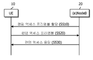
- FIG. 5 illustrates an operation of a UE and a base station in a non-contention based random access procedure.
- MTC 6 illustrates an example of machine type communication (MTC).
- FIG. 7 is a flowchart illustrating a method according to one disclosure of the present specification.
- FIG. 8 is a flowchart illustrating a method according to another disclosure of the present specification.
- FIG. 10 is a block diagram illustrating a wireless communication system in which an embodiment of the present invention is implemented.
- first and second may be used to describe various components, but the components should not be limited by the terms. The terms are used only for the purpose of distinguishing one component from another.
- first component may be referred to as the second component, and similarly, the second component may also be referred to as the first component.
- the terminal may include a user equipment (UE), a mobile equipment (ME), a mobile station (MS), a user terminal (UT), a subscriber station (SS), a wireless device (Wireless Device), It may be called a handheld device or an access terminal (AT).
- the terminal may be a portable device having a communication function such as a mobile phone, a PDA, a smart phone, a wireless modem, a laptop, or the like, or a non-portable device such as a PC or a vehicle-mounted device.
- FIG. 1 shows a wireless communication system to which the present invention is applied.
- E-UTRAN Evolved-UMTS Terrestrial Radio Access Network
- LTE Long Term Evolution
- the E-UTRAN includes a base station (BS) 20 that provides a control plane and a user plane to a user equipment (UE) 10.
- the UE 10 may be fixed or mobile and may have other terms such as terminal, user terminal (UT), mobile station (MS), subscriber station (SS), mobile terminal (MT), and wireless device (Wireless Device).
- the base station 20 refers to a fixed station communicating with the UE 10, and may be referred to in other terms such as an evolved-NodeB (eNB), a base transceiver system (BTS), an access point, and the like.
- eNB evolved-NodeB
- BTS base transceiver system
- access point and the like.
- the base stations 20 may be connected to each other through an X2 interface.
- the base station 20 is connected to a Serving Gateway (S-GW) through an MME (Mobility Management Entity) and an S1-U through an Evolved Packet Core (EPC) 30, more specifically, an S1-MME through an S1 interface.
- S-GW Serving Gateway
- MME Mobility Management Entity
- EPC Evolved Packet Core
- EPC 30 is composed of MME, S-GW and P-GW (Packet Data Network-Gateway).
- the MME has information about the UE's access information or the UE's capability, and this information is mainly used for mobility management of the UE.
- S-GW is a gateway having an E-UTRAN as an endpoint
- P-GW is a gateway having a PDN as an endpoint.
- Layers of the Radio Interface Protocol between the UE and the network are based on the lower three layers of the Open System Interconnection (OSI) reference model, which are well known in communication systems.
- L2 second layer
- L3 third layer
- the RRC Radio Resource Control
- the RRC layer located in the third layer plays a role of controlling radio resources between the UE and the network.
- the RRC layer exchanges RRC messages between the UE and the base station.
- FIG. 2 is a block diagram illustrating a radio protocol architecture for a user plane.
- 3 is a block diagram illustrating a radio protocol structure for a control plane.
- the data plane is a protocol stack for user data transmission
- the control plane is a protocol stack for control signal transmission.
- a physical layer (PHY) layer provides an information transfer service to a higher layer using a physical channel.
- the physical layer is connected to a medium access control (MAC) layer, which is an upper layer, through a transport channel. Data is moved between the MAC layer and the physical layer through the transport channel. Transport channels are classified according to how and with what characteristics data is transmitted over the air interface.
- MAC medium access control
- the physical channel may be modulated by an orthogonal frequency division multiplexing (OFDM) scheme and utilizes time and frequency as radio resources.
- OFDM orthogonal frequency division multiplexing
- the functions of the MAC layer include mapping between logical channels and transport channels and multiplexing / demultiplexing into transport blocks provided as physical channels on transport channels of MAC service data units (SDUs) belonging to the logical channels.
- the MAC layer provides a service to a Radio Link Control (RLC) layer through a logical channel.
- RLC Radio Link Control
- RLC layer Functions of the RLC layer include concatenation, segmentation, and reassembly of RLC SDUs.
- QoS Quality of Service
- the RLC layer has a transparent mode (TM), an unacknowledged mode (UM), and an acknowledged mode (Acknowledged Mode).
- TM transparent mode
- UM unacknowledged mode
- Acknowledged Mode acknowledged mode
- AM Three modes of operation (AM).
- AM RLC provides error correction through an automatic repeat request (ARQ).
- PDCP Packet Data Convergence Protocol
- Functions of the Packet Data Convergence Protocol (PDCP) layer in the user plane include delivery of user data, header compression, and ciphering.
- the functionality of the Packet Data Convergence Protocol (PDCP) layer in the user plane includes the transfer of control plane data and encryption / integrity protection.
- the RRC (Radio Resource Control) layer is defined only in the control plane.
- the RRC layer is responsible for the control of logical channels, transport channels, and physical channels in connection with configuration, re-configuration, and release of radio bearers.
- RB refers to a logical path provided by the first layer (PHY layer) and the second layer (MAC layer, RLC layer, PDCP layer) for data transmission between the user equipment (UE) and the network.
- the establishment of the RB means a process of defining characteristics of a radio protocol layer and a channel to provide a specific service, and setting each specific parameter and operation method.
- RB can be further divided into SRB (Signaling RB) and DRB (Data RB).
- SRB is used as a path for transmitting RRC messages in the control plane
- DRB is used as a path for transmitting user data in the user plane.
- the UE If an RRC connection is established between the RRC layer of the UE (UE) and the RRC layer of the E-UTRAN, the UE is in an RRC connected state (or referred to as RRC connected mode). In this case, it is in an RRC idle state (or RRC idle mode).
- Downlink transmission channels for transmitting data from the network to the UE include a broadcast channel (BCH) for transmitting system information and a downlink shared channel (SCH) for transmitting user traffic or control messages.
- Traffic or control messages of a downlink multicast or broadcast service may be transmitted through a downlink SCH or may be transmitted through a separate downlink multicast channel (MCH).
- uplink transport channels for transmitting data from a UE to a network include a random access channel (RACH) for transmitting an initial control message and an uplink shared channel (SCH) for transmitting user traffic or control messages.
- RACH random access channel
- SCH uplink shared channel
- BCCH broadcast control channel
- PCCH paging control channel
- CCCH common control channel
- MCCH multicast control channel
- MTCH multicast traffic
- the physical channel is composed of several OFDM symbols in the time domain and several sub-carriers in the frequency domain.
- One sub-frame consists of a plurality of OFDM symbols in the time domain.
- the RB is a resource allocation unit and includes a plurality of OFDM symbols and a plurality of subcarriers.
- each subframe may use specific subcarriers of specific OFDM symbols (eg, the first OFDM symbol) of the corresponding subframe for the physical downlink control channel (PDCCH), that is, the L1 / L2 control channel.
- Transmission Time Interval is a unit time of subframe transmission.
- RRC state refers to whether or not the RRC layer of the UE is in logical connection with the RRC layer of the E-UTRAN.If connected, the RRC connected state, if not connected, is RRC idle. This is called the RRC idle state. Since the UE in the RRC connected state has an RRC connection, the E-UTRAN can grasp the existence of the corresponding UE in a cell unit, and thus can effectively control the UE. On the other hand, the UE in the RRC idle state cannot be identified by the E-UTRAN, and is managed by the core netwrok (CN) in units of a tracking area, which is a larger area than a cell. That is, the UE in the RRC idle state is identified only in a large area unit, and must move to the RRC connected state in order to receive a normal mobile communication service such as voice or data.
- CN core netwrok
- the UE When a user first powers up a UE, the UE first searches for an appropriate cell and then stays in an RRC idle state in that cell. When the UE in the RRC idle state needs to establish an RRC connection, the UE establishes an RRC connection with the E-UTRAN through an RRC connection procedure and transitions to the RRC connected state. There are several cases where a UE in RRC idle state needs to establish an RRC connection. For example, an upstream data transmission is necessary due to a user's call attempt, or a paging message is sent from E-UTRAN. If received, a response message may be sent.
- the non-access stratum (NAS) layer located above the RRC layer performs functions such as session management and mobility management.
- EMM-REGISTERED EPS Mobility Management-REGISTERED
- EMM-DEREGISTERED EMM-DEREGISTERED
- the initial UE is in an EMM-DEREGISTERED state, and the UE performs a process of registering with the corresponding network through an initial attach procedure in order to access the network. If the attach procedure is successfully performed, the UE and the MME enter the EMM REGISTERED state.
- an EPS Connection Management (ECM) -IDLE state In order to manage a signaling connection between the UE and the EPC, two states are defined, an EPS Connection Management (ECM) -IDLE state and an ECM-CONNECTED state, and these two states apply to the UE and the MME.
- ECM EPS Connection Management
- ECM-IDLE state makes an RRC connection with the E-UTRAN
- the UE is in the ECM-CONNECTED state.
- the MME in the ECM-IDLE state becomes the ECM-CONNECTED state when it establishes an S1 connection with the E-UTRAN.
- the E-UTRAN does not have context information of the UE.
- the UE in the ECM-IDLE state performs UE-based mobility related procedures such as cell selection procedure or cell reselection procedure without the need of a network command.
- the cell selection procedure means that the UE selects a cell to access a network service.
- the cell reselection procedure means finding the best cell that can be configured as a serving cell.
- the UE when the UE is in the ECM-CONNECTED state, the mobility of the UE is managed by the command of the network.
- the UE In the ECM-IDLE state, if the location of the UE is different from the location known by the network, the UE informs the network of the location of the UE through a tracking area update procedure.
- the system information includes essential information that the UE needs to know in order to connect to the base station. Therefore, the UE must receive all system information before accessing the base station, and must always have the latest system information. And since the system information is information that every UE in a cell should know, the base station periodically transmits the system information.
- the system information includes a master information block (MIB) and a scheduling block (SB). It is divided into SIB (System Information Block).
- MIB master information block
- SB scheduling block
- the MIB allows the UE to know the physical configuration of the cell, such as bandwidth.
- SB informs transmission information of SIBs, for example, a transmission period.
- SIB is a collection of related system information. For example, some SIBs contain only information of neighboring cells, and some SIBs contain only information of an uplink radio channel used by the UE.
- the base station transmits a call message to inform the UE whether to change the system information.
- the call message includes a system information change indicator.
- the UE receives the call message according to the paging DRX, and if the call message includes the system information change indicator, receives the system information transmitted through the logical channel BCCH.
- a base station allocates a designated random access preamble to a specific UE, and the UE provides a non-competitive random access procedure for performing a random access procedure with the random access preamble.
- a contention based random access procedure in which a UE selects one randomly within a specific set and a random access preamble allocated by a base station only to a specific UE are used.
- the non- contention based random access procedure may be used only when requested by the handover process or the command of the base station described above.
- FIG. 4 illustrates an operation of a UE and a base station in a contention based random access procedure.
- a UE selects one random access preamble randomly from a set of random access preambles indicated by system information or a handover command, and transmits the random access preamble. Select to send.
- the UE After transmitting the random access preamble as described above, the UE attempts to receive its random access response within the random access response reception window indicated by the base station through system information or a handover command.
- the random access response information is transmitted in the form of MAC PDU
- the MAC PDU is transmitted in PDSCH.
- the PDCCH is also delivered to the UE to properly receive the information delivered to the PDSCH. That is, the PDCCH includes information of a UE that should receive the PDSCH, frequency and time information of radio resources of the PDSCH, a transmission format of the PDSCH, and the like.
- the UE After the UE succeeds in receiving the PDCCH coming to it, it properly receives the random access response sent to the PDSCH according to the information of the PDCCH.
- the random access response includes a random access preamble identifier (ID), a UL Grant (uplink radio resource), a Temporary C-RNTI (temporary cell identifier), and a Time Alignment Command.
- ID random access preamble identifier
- UL Grant uplink radio resource
- Temporary C-RNTI temporary cell identifier
- Time Alignment Command The reason why the random access preamble discriminator is needed is that since one random access response may include random access response information for one or more UEs, indicating to which UE the UL Grant, Temporary C-RNTI and the TAC are valid. It is for.
- the random access preamble identifier corresponds to the random access preamble selected by the user in step 1.
- the UE When the UE receives a valid random access response to the UE, it processes each of the information included in the random access response. That is, the UE applies the TAC and stores the Temporary C-RNTI.
- the UE applies the TAC and stores the Temporary C-RNTI.
- the UL Grant data stored in the buffer of the UE or newly generated data is transmitted to the base station.
- an identifier of the UE must be included essentially. This is because, in the contention-based random access procedure, it is not possible to determine which UEs perform the random access procedure in the base station, since the UE needs to be identified for future collision resolution.
- there are two methods for including the identifier of the UE there are two methods for including the identifier of the UE.
- the UE transmits its cell identifier through the UL Grant.
- the UE transmits its own unique identifier (eg, S-TMSI or Random Id). In general, the unique identifier is longer than the cell identifier. If the UE has transmitted data through the UL Grant, the UE starts a contention resolution timer.
- the UE After the UE transmits data including its identifier through the UL Grant included in the random access response, it waits for an indication of the base station to resolve the collision. That is, it attempts to receive a PDCCH to receive a specific message.
- the UE determines that the random access procedure has been normally performed and ends the random access procedure.
- the PDCCH is received through the temporary cell identifier before the conflict resolution timer expires, the data transmitted by the PDSCH indicated by the PDCCH is checked. If the unique identifier is included in the content of the data, the UE determines that the random access procedure has been normally performed, and terminates the random access procedure.
- FIG. 5 illustrates an operation of a UE and a base station in a non-contention based random access procedure.
- the non- contention-based random access process by receiving the random access response information, it is determined that the random access process is normally performed, and ends the random access process.
- the non-contention based random access procedure may exist firstly in the case of a handover procedure and secondly, in a case requested by a command of a base station.
- the contention-based random access procedure may be performed in both cases.
- the UE transmits the preamble to the base station after receiving the random access preamble assigned to itself as the base station.
- step S530 The method of receiving random access response information is the same as in the contention-based random access procedure.
- the reason why collision occurs in the random access process is because the number of random access preambles is basically finite. That is, since the base station cannot grant UE-specific random access preamble to all UEs, the UE randomly selects and transmits one of the common random access preambles. Accordingly, when two or more UEs select and transmit the same random access preamble through the same PRACH resource, the base station determines that one random access preamble is transmitted from one UE. For this reason, the base station transmits a random access response to the UE, and predicts that the random access response will be received by one UE.
- One method is to use a contention resolution timer (hereinafter referred to as a CR timer), and the other is to transmit an identifier of a successful UE to the UEs.
- the former case is used when the UE already has a unique cell identifier (C-RNTI) before the random access procedure. That is, the UE which already has the cell identifier transmits data including its cell identifier to the base station according to the random access response, and operates the collision resolution timer. Then, if the PDCCH information including its cell identifier is received before the conflict resolution timer expires, the UE determines that it has succeeded in the competition, and ends the random access process normally.
- C-RNTI unique cell identifier
- the PDCCH containing the cell identifier is not transmitted before the conflict resolution timer expires, it is determined that it has failed in the race, re-performs the random access procedure, or notifies the upper layer of the failure. Done.
- the latter case of the collision resolution method that is, a method of transmitting an identifier of a successful UE is used when the UE does not have a unique cell identifier before the random access procedure. That is, when the UE itself does not have a cell identifier, the UE transmits data including an identifier higher than the cell identifier (S-TMSI or Random Id) according to UL Grant information included in the random access response, and the UE operates a collision resolution timer.
- S-TMSI or Random Id an identifier higher than the cell identifier
- the UE determines that the random access procedure is successful.
- the conflict resolution timer expires, if the data including its higher identifier is not transmitted to the DL-SCH, the UE determines that the random access procedure has failed.
- MTC 6 illustrates an example of machine type communication (MTC).
- Machine Type Communication is an exchange of information through the base station 200 between MTC devices 100 without human interaction or information through a base station between the MTC device 100 and the MTC server 700.
- MTC Machine Type Communication
- M2M Machine to Machine
- H2H human to human
- the MTC server 700 is an entity that communicates with the MTC device 100.
- the MTC server 700 executes an MTC application and provides an MTC specific service to the MTC device.
- the MTC device 100 is a wireless device that provides MTC communication and may be fixed or mobile.
- the services offered through MTC are different from those in existing human-involved communications, and there are various categories of services such as tracking, metering, payment, medical services, and remote control. exist. More specifically, services provided through the MTC may include meter reading, level measurement, utilization of surveillance cameras, inventory reporting of vending machines, and the like.
- the uniqueness of the MTC device is that the amount of data transmitted is small and the up / down link data transmission and reception occur occasionally. Therefore, it is effective to lower the cost of the MTC device and reduce battery consumption in accordance with such a low data rate.
- Table 1 Type of MTC Device Data Processing Speed Error Rate Requirements Delay sensitivity Smart meter lowness lowness lowness Vehicle management lowness lowness Middle price Point of sale terminal (POS) lowness middle height Live video lowness lowness lowness
- the MTC device does not require a wide range of services, but has a feature of requiring only a small number of special services.
- MTC devices may exist individually for each service and use, a huge number of MTC devices may be located in the coverage of the base station. However, since such a large number of MTC devices are placed in the coverage of the base station, there is a possibility that the quality of H2H communication may be degraded.
- the 3GPP Release 10 standard document considers adding “Delay tolerant access” as the RRC establishment cause value. This allows the network to reject RRC connection requests with an extended wait timer. However, even with this solution, it is not effective when the MTC device continuously attempts random access and transmits an RRC connection request. As a better solution, consider preventing random access attempts if delays are acceptable for the MTC device's access. This solution can be very effective in terms of battery savings.
- smartphones are currently installed with various kinds of applications running in the background. While data by some of the many applications may be delayed, data by some other applications may be very sensitive to delay. However, these are not distinguished and are inefficient.
- a network delivers information for an access class barring (ACB) differently for each UE to block access of a specific UE.
- ACB access class barring
- the disclosures of the present disclosure aim to provide a method of performing access control on a device or a service having a high delay tolerance in order to solve the above problem.
- one disclosure of the present specification is intended to propose a method for preventing a network from being congested by data having a high delay tolerance among data generated by an MTC device (or an M2M device).
- one disclosure of the present specification proposes a method for adding a condition that an MTC device (or M2M device) generating high delay tolerance data can initiate random access.
- FIG. 7 is a flowchart illustrating a method according to one disclosure of the present specification.
- the MTC device selects a maximum delay allowance T value (S103).
- the maximum delay tolerance T value may be any one of 1, 2, 4, 8, 16, 32, 64, 128, 256, 512, and 1024.
- the MTC device may select any one of the maximum delay tolerance T values according to its type and service type. More specifically, if the type of the MTC device can perform various services, one of the maximum delay tolerance T values may be selected according to the type of the service that triggered the current random access procedure.
- the MTC device obtains a load interworking N value broadcast in the network (S105), and checks whether the load interworking N value is 0 (S107).
- the load interlocking N value is T / 1024, T / 512, T / 256, T / 128, T / 64, T / 32, T / 16, T / 8, T / 4, T / 2, T, 2T, It may be any one of 4T, 8T, 16T, 32T, 64T, 128T, 256T, 512T, and 1024T.
- the load interlocking N value is 0, it waits until the load interlocking N value is not 0 (S108). That is, it waits until a non-zero load interworking N value is broadcast.
- the MTC device calculates a Tf value, which is a tolerance factor, based on the maximum delay tolerance value T and the load-linked N value (S109).
- the calculated Tf value may be any one of 1, 2, 4, 8, 16, 32, 64, 128, 256, 512 and 1024.
- SFN means a system frame number.
- the UE 100 transmits a random access preamble on the subframe of the SFN (S113).
- the UEID may mean an international mobile subscriber identity (IMSI) mod 1024 SFN.
- IMSI international mobile subscriber identity
- the allowable factor Tf may be calculated differently for each MTC device based on the T value, which is the maximum delay allowable value, and the load interworking N value.
- the tolerance factor Tf can be calculated as follows.
- the tolerance factor Tf may be stored in the MTC device differently according to the delay tolerance of the MTC device. If the MTC device can perform various services, different Tf values may be stored in the MTC device according to the delay tolerance of each service.
- This first modification has the advantage that the problem can be solved only by the improvement of the MTC device without improvement in the network.
- the network may broadcast the value of the tolerance factor Tf in the system information.
- the tolerance factor Tf may be included in SIB2 and broadcast.
- the MTC device may not perform a random access procedure.
- the MTC device cannot perform a random access procedure.
- This third variant can be used to completely block access of the MTC device in an emergency.
- the MTC device may randomly select a value within a range of setting a specific value as a minimum value and a maximum delay allowable value T as a maximum value at a uniform probability according to its type and service type.
- the UE waits for the selected value and then attempts a random access procedure in a subframe in which a random access preamble resource exists.
- the specific value is a specific constant value equal to or greater than zero and the maximum delay tolerance T.
- the maximum number of random access preambles that can be transmitted in a specific length of time may be determined.
- the maximum number of times is set to a value with which the maximum delay tolerance T is associated.
- the time intervals appear in succession repeatedly in time.
- FIG. 8 is a flowchart illustrating a method according to another disclosure of the present specification.
- the scheme illustrated in FIG. 8 further includes processes S115, S117, and S119 compared to the scheme illustrated in FIG. 7. Therefore, the following description will focus on the processes S115, S117, and S119.
- the MTC device After transmitting the random access preamble (S113), the MTC device determines whether it is successful (S115).
- the MTC device calculates a random waiting time Wdt (S119).
- the random wait time Wdt means a wait time until the next random access attempt.
- the MTC device waits until the timer according to the calculated random wait time Wdt expires (S121).
- the MTC device waits for the backoff time (S117), it may further wait until the timer according to the random waiting time Wdt expires (S119).
- the random wait time Wdt may be generated by a random number generation function.
- the random wait time Wdt generated by the random number generation function may vary depending on the delay tolerance of the MTC device.
- the relationship between the allowable delay and the wait time may be as shown in the table below.
- the random waiting time Wdt can be calculated as follows.
- the random wait time Wdt may be generated by the network and included in the system information and broadcasted.
- the random wait time Wdt may be included in SIB2 and broadcasted.
- the random waiting time Wdt may be calculated based on a d1 value (ie, a value according to the delay tolerance factor of the MTC device) and a d2 value (a load interworking value broadcast from the network).
- a d1 value ie, a value according to the delay tolerance factor of the MTC device
- a d2 value a load interworking value broadcast from the network.
- the Wdt may be calculated as follows.
- an upper limit and a lower limit may be imposed on the arbitrary waiting time Wdt. Also, if the network is lightly loaded, the d2 value may be negative in order for the MTC device to restart the random access procedure as soon as possible.
- UE # a 10a, UE # b 10b, and MTC device 100 exist within coverage of the base station 200.
- embodiments described so far may be implemented through various means.
- embodiments of the present invention may be implemented by hardware, firmware, software, or a combination thereof. Specifically, this will be described with reference to FIG. 12.
- FIG. 10 is a block diagram illustrating a wireless communication system in which an embodiment of the present invention is implemented.
- the base station 200 includes a processor 201, a memory 202, and an RF unit 203.
- the memory 202 is connected to the processor 201 and stores various information for driving the processor 201.
- the RF unit 203 is connected to the processor 201 to transmit and / or receive a radio signal.
- the processor 201 implements the proposed functions, processes and / or methods. In the above-described embodiment, the operation of the base station may be implemented by the processor 201.
- the MTC device 100 includes a processor 101, a memory 102, and an RF unit 103.
- the memory 102 is connected to the processor 101 and stores various information for driving the processor 101.
- the RF unit 103 is connected to the processor 101 and transmits and / or receives a radio signal.
- the processor 101 implements the proposed functions, processes and / or methods. In the above-described embodiment, the operation of the MTC device may be implemented by the processor 101.
- the processor may include application-specific integrated circuits (ASICs), other chipsets, logic circuits, and / or data processing devices.
- the memory may include read-only memory (ROM), random access memory (RAM), flash memory, memory card, storage medium and / or other storage device.
- the RF unit may include a baseband circuit for processing a radio signal.
- the above-described technique may be implemented as a module (process, function, etc.) for performing the above-described function.
- the module may be stored in memory and executed by a processor.
- the memory may be internal or external to the processor and may be coupled to the processor by various well known means.
Landscapes
- Engineering & Computer Science (AREA)
- Computer Networks & Wireless Communication (AREA)
- Signal Processing (AREA)
- Mobile Radio Communication Systems (AREA)
Abstract
La présente invention concerne, selon un mode de réalisation, un procédé destiné à exécuter une procédure d'accès aléatoire dans un dispositif de communication de type machine (MTC). Le procédé peut comporter les étapes consistant: lorsqu'une procédure d'accès aléatoire est déclenchée, à faire déterminer par le dispositif de MTC, une valeur maximale T de tolérance de retard d'après le type du dispositif de MTC et le type d'un service par lequel la procédure d'accès aléatoire a été déclenchée; à déterminer un facteur de tolérance Tf d'après la valeur maximale T de tolérance de retard; à sélectionner, d'après le facteur de tolérance Tf, une trame radio dans laquelle doit être émis un préambule d'accès aléatoire; et à émettre le préambule d'accès aléatoire dans la trame radio sélectionnée.
Applications Claiming Priority (2)
| Application Number | Priority Date | Filing Date | Title |
|---|---|---|---|
| IN2391CH2014 | 2014-05-14 | ||
| IN2391/CHE/2014 | 2014-05-14 |
Publications (1)
| Publication Number | Publication Date |
|---|---|
| WO2015174745A1 true WO2015174745A1 (fr) | 2015-11-19 |
Family
ID=54480224
Family Applications (1)
| Application Number | Title | Priority Date | Filing Date |
|---|---|---|---|
| PCT/KR2015/004821 Ceased WO2015174745A1 (fr) | 2014-05-14 | 2015-05-14 | Procédé d'exécution d'une procédure d'accès aléatoire dans un dispositif de mtc |
Country Status (1)
| Country | Link |
|---|---|
| WO (1) | WO2015174745A1 (fr) |
Citations (4)
| Publication number | Priority date | Publication date | Assignee | Title |
|---|---|---|---|---|
| WO2011136558A2 (fr) * | 2010-04-28 | 2011-11-03 | 엘지전자 주식회사 | Procédé et appareil pour l'exécution de procédures d'accès direct dans un système de communication sans fil |
| WO2012015206A2 (fr) * | 2010-07-25 | 2012-02-02 | 엘지전자 주식회사 | Procédé pour propager un accès aléatoire, procédé pour propager et réaliser un accès aléatoire et dispositif associé |
| WO2012070879A2 (fr) * | 2010-11-25 | 2012-05-31 | 엘지전자 주식회사 | Procédé et appareil de distribution d'accès aléatoire dans système à accès sans fil |
| US20130170479A1 (en) * | 2011-11-11 | 2013-07-04 | Mo-Han Fong | Random backoff for extended access barring |
-
2015
- 2015-05-14 WO PCT/KR2015/004821 patent/WO2015174745A1/fr not_active Ceased
Patent Citations (4)
| Publication number | Priority date | Publication date | Assignee | Title |
|---|---|---|---|---|
| WO2011136558A2 (fr) * | 2010-04-28 | 2011-11-03 | 엘지전자 주식회사 | Procédé et appareil pour l'exécution de procédures d'accès direct dans un système de communication sans fil |
| WO2012015206A2 (fr) * | 2010-07-25 | 2012-02-02 | 엘지전자 주식회사 | Procédé pour propager un accès aléatoire, procédé pour propager et réaliser un accès aléatoire et dispositif associé |
| WO2012070879A2 (fr) * | 2010-11-25 | 2012-05-31 | 엘지전자 주식회사 | Procédé et appareil de distribution d'accès aléatoire dans système à accès sans fil |
| US20130170479A1 (en) * | 2011-11-11 | 2013-07-04 | Mo-Han Fong | Random backoff for extended access barring |
Non-Patent Citations (1)
| Title |
|---|
| MEDIATEK INC.: "Access barring for low cost MTE UE", R2-142294, 3GPP TSG RAN2 MEETING #86, 10 May 2014 (2014-05-10), Seoul, South Korea, XP050790206, Retrieved from the Internet <URL:http://www.3gpp.org/ftp/tsg_ran/WG2_RL2/TSGR2_86/docs> * |
Similar Documents
| Publication | Publication Date | Title |
|---|---|---|
| WO2011136558A2 (fr) | Procédé et appareil pour l'exécution de procédures d'accès direct dans un système de communication sans fil | |
| WO2017052144A1 (fr) | Procédé pour réaliser une procédure d'accès aléatoire dans un mode de couverture améliorée dans un système de communication sans fil et dispositif associé | |
| WO2011139043A2 (fr) | Procédé et appareil pour réaliser un processus d'accès aléatoire dans un système de communication sans fil | |
| WO2016144082A1 (fr) | Procédé d'exploitation de procédure d'accès aléatoire dans un système de communication sans fil, et dispositif à cet effet | |
| WO2017065468A1 (fr) | Procédé et appareil de contrôle de procédure d'attente pour une amélioration de couverture dans un système de communications sans fil | |
| WO2016144084A1 (fr) | Procédé d'exécution d'une procédure d'accès aléatoire rapide dans un système de communication sans fil et dispositif associé | |
| WO2018203633A1 (fr) | Procédé et appareil permettant d'obtenir des informations de système | |
| WO2013005972A2 (fr) | Procédé permettant à un terminal de contrôler un groupe d'avance de synchronisation dans un système de communication sans fil, et dispositif pour la mise en œuvre dudit procédé | |
| WO2013022298A2 (fr) | Système et procédé permettant d'appliquer une interdiction d'accès étendu dans un système de communication sans fil | |
| WO2017026806A1 (fr) | Procédé et appareil permettant de notifier une mise à jour d'informations du système (si), une mise à jour d'interdiction d'accès étendu (eab) et un message de système d'avertissement public (pws) dans un système de communication sans fil | |
| WO2011112051A2 (fr) | Procédé et appareil pour mtc dans un système de communication sans fil | |
| WO2016163746A1 (fr) | Procédé permettant de réaliser une procédure d'accès aléatoire dans une agrégation de porteuses avec au moins une cellule secondaire fonctionnant dans un spectre non autorisé et dispositif associé | |
| WO2012134072A2 (fr) | Procédé et appareil de gestion d'alignement temporel en liaison montante | |
| WO2012150801A2 (fr) | Procédé pour effectuer un accès aléatoire dans un système de communication sans fil, et dispositif de mise en œuvre | |
| WO2013048137A2 (fr) | Procédé et dispositif d'accès direct dans un système de communication sans fil prenant en charge plusieurs porteuses | |
| WO2019004690A1 (fr) | Procédé et appareil permettant de configurer de multiples canaux de commande communs dans un système de communication sans fil | |
| WO2013043007A2 (fr) | Procédé et appareil d'accès aléatoire dans un système de communication sans fil | |
| WO2013073809A1 (fr) | Procede et appareil pour le controle de l'acces au reseau dans un systeme de communication sans fil | |
| WO2013022285A2 (fr) | Procédé et dispositif d'accès aléatoire dans un système de communication sans fil prenant en charge une onde multi-porteuse | |
| WO2016167506A1 (fr) | Procédé pour générer un élément de commande de contrôle d'accès au support (mac) dans un système d'agrégation de porteuses et dispositif associé | |
| WO2017078384A1 (fr) | Procédé de communication utilisant une bande étroite, et dispositif mtc | |
| WO2016163687A1 (fr) | Procédé pour effectuer une procédure d'accès aléatoire dans une agrégation de porteuses avec au moins une cellule secondaire fonctionnant dans un spectre sans licence, et dispositif correspondant | |
| WO2017191994A1 (fr) | Procédé et appareil de réception de bloc osi dans un système de communication sans fil | |
| WO2012134099A2 (fr) | Procédé pour la transmission/réception par un équipement d'utilisateur de données dans un système de communication sans fil et appareil associé | |
| WO2019194409A1 (fr) | Procédé et appareil pour interdire une procédure de resélection de cellule durant une communication de données par un équipement utilisateur dans un système de communications sans fil |
Legal Events
| Date | Code | Title | Description |
|---|---|---|---|
| 121 | Ep: the epo has been informed by wipo that ep was designated in this application |
Ref document number: 15793261 Country of ref document: EP Kind code of ref document: A1 |
|
| NENP | Non-entry into the national phase |
Ref country code: DE |
|
| 122 | Ep: pct application non-entry in european phase |
Ref document number: 15793261 Country of ref document: EP Kind code of ref document: A1 |