WO2015177880A1 - 圧力緩衝装置および減衰力発生部材 - Google Patents
圧力緩衝装置および減衰力発生部材 Download PDFInfo
- Publication number
- WO2015177880A1 WO2015177880A1 PCT/JP2014/063397 JP2014063397W WO2015177880A1 WO 2015177880 A1 WO2015177880 A1 WO 2015177880A1 JP 2014063397 W JP2014063397 W JP 2014063397W WO 2015177880 A1 WO2015177880 A1 WO 2015177880A1
- Authority
- WO
- WIPO (PCT)
- Prior art keywords
- valve
- flow path
- axial direction
- cylinder
- piston body
- Prior art date
- Legal status (The legal status is an assumption and is not a legal conclusion. Google has not performed a legal analysis and makes no representation as to the accuracy of the status listed.)
- Ceased
Links
Images




Classifications
-
- F—MECHANICAL ENGINEERING; LIGHTING; HEATING; WEAPONS; BLASTING
- F16—ENGINEERING ELEMENTS AND UNITS; GENERAL MEASURES FOR PRODUCING AND MAINTAINING EFFECTIVE FUNCTIONING OF MACHINES OR INSTALLATIONS; THERMAL INSULATION IN GENERAL
- F16F—SPRINGS; SHOCK-ABSORBERS; MEANS FOR DAMPING VIBRATION
- F16F9/00—Springs, vibration-dampers, shock-absorbers, or similarly-constructed movement-dampers using a fluid or the equivalent as damping medium
- F16F9/32—Details
- F16F9/50—Special means providing automatic damping adjustment, i.e. self-adjustment of damping by particular sliding movements of a valve element, other than flexions or displacement of valve discs; Special means providing self-adjustment of spring characteristics
- F16F9/512—Means responsive to load action, i.e. static load on the damper or dynamic fluid pressure changes in the damper, e.g. due to changes in velocity
- F16F9/5126—Piston, or piston-like valve elements
-
- F—MECHANICAL ENGINEERING; LIGHTING; HEATING; WEAPONS; BLASTING
- F16—ENGINEERING ELEMENTS AND UNITS; GENERAL MEASURES FOR PRODUCING AND MAINTAINING EFFECTIVE FUNCTIONING OF MACHINES OR INSTALLATIONS; THERMAL INSULATION IN GENERAL
- F16F—SPRINGS; SHOCK-ABSORBERS; MEANS FOR DAMPING VIBRATION
- F16F9/00—Springs, vibration-dampers, shock-absorbers, or similarly-constructed movement-dampers using a fluid or the equivalent as damping medium
- F16F9/10—Springs, vibration-dampers, shock-absorbers, or similarly-constructed movement-dampers using a fluid or the equivalent as damping medium using liquid only; using a fluid of which the nature is immaterial
- F16F9/14—Devices with one or more members, e.g. pistons, vanes, moving to and fro in chambers and using throttling effect
- F16F9/16—Devices with one or more members, e.g. pistons, vanes, moving to and fro in chambers and using throttling effect involving only straight-line movement of the effective parts
- F16F9/18—Devices with one or more members, e.g. pistons, vanes, moving to and fro in chambers and using throttling effect involving only straight-line movement of the effective parts with a closed cylinder and a piston separating two or more working spaces therein
- F16F9/185—Bitubular units
-
- F—MECHANICAL ENGINEERING; LIGHTING; HEATING; WEAPONS; BLASTING
- F16—ENGINEERING ELEMENTS AND UNITS; GENERAL MEASURES FOR PRODUCING AND MAINTAINING EFFECTIVE FUNCTIONING OF MACHINES OR INSTALLATIONS; THERMAL INSULATION IN GENERAL
- F16F—SPRINGS; SHOCK-ABSORBERS; MEANS FOR DAMPING VIBRATION
- F16F9/00—Springs, vibration-dampers, shock-absorbers, or similarly-constructed movement-dampers using a fluid or the equivalent as damping medium
- F16F9/32—Details
-
- F—MECHANICAL ENGINEERING; LIGHTING; HEATING; WEAPONS; BLASTING
- F16—ENGINEERING ELEMENTS AND UNITS; GENERAL MEASURES FOR PRODUCING AND MAINTAINING EFFECTIVE FUNCTIONING OF MACHINES OR INSTALLATIONS; THERMAL INSULATION IN GENERAL
- F16F—SPRINGS; SHOCK-ABSORBERS; MEANS FOR DAMPING VIBRATION
- F16F9/00—Springs, vibration-dampers, shock-absorbers, or similarly-constructed movement-dampers using a fluid or the equivalent as damping medium
- F16F9/32—Details
- F16F9/3207—Constructional features
- F16F9/3214—Constructional features of pistons
-
- F—MECHANICAL ENGINEERING; LIGHTING; HEATING; WEAPONS; BLASTING
- F16—ENGINEERING ELEMENTS AND UNITS; GENERAL MEASURES FOR PRODUCING AND MAINTAINING EFFECTIVE FUNCTIONING OF MACHINES OR INSTALLATIONS; THERMAL INSULATION IN GENERAL
- F16F—SPRINGS; SHOCK-ABSORBERS; MEANS FOR DAMPING VIBRATION
- F16F9/00—Springs, vibration-dampers, shock-absorbers, or similarly-constructed movement-dampers using a fluid or the equivalent as damping medium
- F16F9/32—Details
- F16F9/34—Special valve constructions; Shape or construction of throttling passages
- F16F9/3405—Throttling passages in or on piston body, e.g. slots
-
- F—MECHANICAL ENGINEERING; LIGHTING; HEATING; WEAPONS; BLASTING
- F16—ENGINEERING ELEMENTS AND UNITS; GENERAL MEASURES FOR PRODUCING AND MAINTAINING EFFECTIVE FUNCTIONING OF MACHINES OR INSTALLATIONS; THERMAL INSULATION IN GENERAL
- F16F—SPRINGS; SHOCK-ABSORBERS; MEANS FOR DAMPING VIBRATION
- F16F9/00—Springs, vibration-dampers, shock-absorbers, or similarly-constructed movement-dampers using a fluid or the equivalent as damping medium
- F16F9/32—Details
- F16F9/34—Special valve constructions; Shape or construction of throttling passages
- F16F9/348—Throttling passages in the form of annular discs or other plate-like elements which may or may not have a spring action, operating in opposite directions or singly, e.g. annular discs positioned on top of the valve or piston body
- F16F9/3481—Throttling passages in the form of annular discs or other plate-like elements which may or may not have a spring action, operating in opposite directions or singly, e.g. annular discs positioned on top of the valve or piston body characterised by shape or construction of throttling passages in piston
Definitions
- the present invention relates to a pressure buffer device and a damping force generating member.
- a pressure buffer device described in Patent Document 1 is provided in a cylinder, a piston, a piston rod, a passage through which a working fluid flows by sliding of the piston, and a part of the passage, and controls the flow of the working fluid.
- a damping force generation mechanism for generating a damping force.
- the damping force generation mechanism is protruded between the outer sheet and the inner sheet, the protruding height is lower than that of the outer sheet, is equal to or greater than the inner sheet, and extends radially between the plurality of openings.
- a disk support portion for supporting the disk.
- the pressure buffer device described in Patent Document 2 is a leaf valve in which a rear surface on the base end side is supported via a ring seat, abuts against the boss portion and the seat portion, and opens and closes an opening window formed at the outlet end of the port. It has.
- the ring seat is supported by a valve stopper having a tapered surface in which a gradient rises from the base end side toward the outer end side.
- a plurality of protrusions are provided on the outer peripheral side of the boss portion along the circumferential direction so as to be continuous with the end face of the boss portion and protrude outward from the outer end of the ring seat.
- An object of the present invention is to suppress variations in damping force generated in a pressure buffer device.
- the present invention provides a cylinder for storing fluid, a rod whose one end is accommodated in the cylinder, the other end projects from the opening of the cylinder, and moves in the cylinder axial direction.
- a damping force generation unit that generates a damping force in the relative movement of the rod with respect to the cylinder, and the damping force generation unit forms a flow path through which a fluid flows as the rod moves relative to the cylinder.
- the pressure buffering device has an extending portion that extends from the outside of the annular projecting portion to the inside of the flow passage port of the flow passage and projects in the axial direction from the flow passage forming portion toward the valve.
- the present invention provides a cylinder for storing fluid, and an end on one side is accommodated in the cylinder, and an end on the other side protrudes from the opening of the cylinder and moves in the cylinder axial direction.
- a rod and a damping force generator that generates a damping force in the relative movement of the rod with respect to the cylinder, and the damping force generator is formed with a flow path through which a fluid flows as the rod moves relative to the cylinder.
- a flow path forming portion a valve that opens and closes the flow path of the flow path forming portion, an annular protrusion that is formed in an annular shape and projects in the axial direction of the flow path forming portion from the flow path forming portion toward the valve,
- the pressure buffering device further includes an extending part that extends further from the outer side of the annular projecting part and is formed so that a projecting height from the flow channel forming part is lower than the annular projecting part.
- the present invention provides a flow path forming portion in which a flow path for fluid to flow with relative movement of the rod with respect to the cylinder is formed, and a shaft formed in an annular shape. Attenuating provided with an annular projecting portion projecting in the direction and an extending portion extending from the outside of the annular projecting portion inward in the radial direction of the flow channel forming portion to the flow channel port of the flow channel and projecting axially from the flow channel forming portion It is a force generating member.
- FIG. 1 is an overall configuration diagram of a hydraulic shock absorber according to a first embodiment.
- (A)-(c) is a figure which shows the piston body of 1st Embodiment.
- (A) And (b) shows the flow of the oil in the piston part of the hydraulic shock absorber of the first embodiment. It is a figure which shows the flow of the oil in the oil path opening of a piston body.
- (A)-(c) is a figure which shows the piston body of 2nd Embodiment.
- (A)-(c) is a figure which shows the modification (modification 1) of the piston body of 2nd Embodiment.
- (A)-(c) is a figure which shows the piston body of 3rd Embodiment.
- (A)-(c) is a figure which shows the modification (modification 2) of the piston body of 3rd Embodiment.
- (A)-(c) is a figure which shows the piston body of 4th Embodiment.
- (A)-(c) is a figure which shows the modification (modification 3) of the piston body of 4th Embodiment.
- (A)-(c) is a figure which shows the piston body of 5th Embodiment.
- (A) is a figure which shows the piston body of 6th Embodiment
- (b) is a figure which shows the piston body of 7th Embodiment. It is a fragmentary sectional view of the piston body of an 8th embodiment.
- (A)-(c) is a figure which shows the hydraulic shock absorber of the modifications 4-6.
- (A)-(c) is a figure which shows the hydraulic shock absorber of the modifications 7-9.
- FIG. 1 is an overall configuration diagram of a hydraulic shock absorber 1 according to the first embodiment.
- the longitudinal direction of the hydraulic shock absorber 1 shown in FIG. 1 is referred to as “axial direction”.
- the lower side of the hydraulic shock absorber 1 is referred to as “one side”
- the upper side of the hydraulic shock absorber 1 is referred to as “the other side”.
- the horizontal direction of the hydraulic shock absorber 1 shown in FIG. 1 is referred to as “radial direction”
- the central axis side is referred to as “inner side”
- the side away from the central axis is referred to as “outer side”.
- the hydraulic shock absorber 1 includes a first cylinder 11 that contains oil, a second cylinder 12, and a part of the oil enters the first cylinder 11 and moves in the axial direction. It has a possible piston rod 21, a piston portion 100 that is fixed to the piston rod 21 and moves inside the first cylinder 11, and a bottom valve portion 60 provided at the bottom of one side of the first cylinder 11.
- the hydraulic shock absorber 1 has a so-called double pipe structure including a first cylinder 11 and a second cylinder 12 in order from the inner side to the outer side in the radial direction.
- One end (bottom) of the first cylinder 11 is closed by the bottom valve portion 60.
- one end of the second cylinder 12 is closed by a bottom lid 13.
- the other end (upper part) of the first cylinder 11 and the second cylinder 12 is blocked by the rod guide 14, the oil seal 15 and the cap 16 so that the piston rod 21 can pass therethrough.
- a reservoir chamber R which is a cylindrical space, is formed between the first cylinder 11 and the second cylinder 12.
- the reservoir chamber R contains oil, and gas is sealed on the other side of the reservoir chamber R.
- Piston Rod 21 As shown in FIG. 1, a part of the piston rod 21 on one side enters the inside of the first cylinder 11, and the remaining part on the other side is exposed to the outside of the first cylinder 11, along the axial direction. It can be moved. Moreover, the piston rod 21 is provided with the piston part 100 in the edge part of one side. Then, the piston rod 21 and the piston portion 100 move integrally in the axial direction. The piston portion 100 is provided to be movable in the axial direction along the inner peripheral surface of the cylinder.
- the piston portion 100 includes a piston body 30 in which a plurality of oil passages (described later) penetrating in the axial direction are formed, and a first pressure side valve portion 40 provided on the other side of the piston body 30. And a first extension side valve portion 50 provided on one side of the piston body 30.
- the piston portion 100 includes a first oil chamber Y1 that is a space on one side in the axial direction (lower side in FIG. 1) and a second side in the axial direction (upper side in FIG. 1). ) To the second oil chamber Y2, which is a space.
- the bottom valve portion 60 is provided at one end of the hydraulic shock absorber 1, and separates the reservoir chamber R and the first oil chamber Y1.
- the bottom valve portion 60 includes a bottom piston body 61 in which a plurality of oil passages 61R penetrating in the axial direction is formed, and a second expansion side valve portion provided on the other side (first oil chamber Y1 side) of the bottom piston body 61. 622 and a second pressure side valve portion 621 provided on one side (reservoir chamber R side) of the bottom piston body 61.
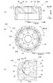
- FIG. 2 is a diagram illustrating the piston body 30 according to the first embodiment.
- 2A is a top view of the piston body 30 as viewed from the other side
- FIG. 2B is a sectional view taken along the line IIb-IIb of the piston body 30 shown in FIG. 2A
- FIG. It is the fragmentary perspective view which looked at the piston body 30 from the other side.
- the piston rod 21, the first pressure side valve portion 40, and the first extension side valve portion 50 are shown together.
- the hydraulic shock absorber 1 pressure shock absorber
- the hydraulic shock absorber 1 includes a first cylinder 11 (cylinder) that contains oil (fluid) and an end portion on one side inside the first cylinder 11. And a piston rod 21 (rod) whose end on the other side protrudes from the opening of the first cylinder 11 and moves in the cylinder axial direction, and a damping force in the relative movement of the piston rod 21 with respect to the first cylinder 11
- a piston portion 100 (a damping force generating portion, a damping force generating member).
- the piston portion 100 includes a piston body 30 (flow passage forming portion) in which a first pressure-side oil passage 32 (flow passage) through which oil flows as the piston rod 21 moves relative to the first cylinder 11 is formed.
- a first pressure side valve portion 40 (valve) that opens and closes the first pressure side oil passage 32 of the piston body 30, and is formed in an annular shape in the axial direction of the piston body 30 from the piston body 30 toward the first pressure side valve portion 40.
- a projecting inner annular portion 34 (annular projecting portion), and extending radially inward of the piston body 30 from the outer side of the inner annular portion 34 to the inner side of the second oil passage port 322 of the first pressure side oil passage 32, And an extending portion 35 protruding in the axial direction toward the first pressure side valve portion 40.
- the piston body 30 includes a through hole 31 extending in the axial direction, a first pressure side oil passage 32 and a first extension side oil formed in the piston body 30.
- an outer annular portion 36 provided.
- the piston body 30 is provided on the one side inner annular portion 37 provided on one side and on the one side and further provided on the radially outer side of the one side inner annular portion 37. Side outer annular portion 38.
- the through hole 31 is a hole formed in a substantially cylindrical shape as shown in FIGS. 2 (a) to 2 (c), and the piston rod 21 is inserted as shown in FIG. 2 (b).
- the first pressure side oil passage 32 includes a first oil passage port 321 that opens toward the first oil chamber Y1 on one side (see FIG. 1) and a second oil chamber on the other side. And a second oil passage port 322 that opens toward Y2 (see FIG. 1).
- the first pressure side oil passage 32 enables oil to flow between the first oil chamber Y1 and the second oil chamber Y2 during a compression stroke described later.
- the 1st pressure side oil path 32 is provided in the multiple places (8 places in this embodiment) at substantially equal intervals in the circumferential direction, as shown to Fig.2 (a).
- Each second oil passage port 322 is formed in a substantially rectangular shape as shown in FIG.
- Each of the second oil passage ports 322 is arranged outside the extending portion 35 in the radial direction, not between the two extending portions 35 adjacent in the circumferential direction.
- the first extension side oil passage 33 is directed toward the third oil passage port 333 that opens toward the first oil chamber Y1 (see FIG. 1) on one side and the second oil chamber Y2 (see FIG. 1) on the other side. And a fourth oil passage port 334 that opens.
- the first extension side oil passage 33 enables oil to flow between the second oil chamber Y2 and the first oil chamber Y1 during an extension stroke described later.
- stretching side oil path 33 is provided in multiple places (8 places in this embodiment) at substantially equal intervals in the circumferential direction, as shown to Fig.2 (a).
- Each fourth oil passage port 334 is formed in a substantially circular shape as shown in FIG.
- Each fourth oil passage port 334 is disposed outside the second oil passage port 322 of the first pressure side oil passage 32 in the radial direction.
- the inner annular portion 34 is formed in a substantially annular shape on the outer periphery of the through hole 31 as shown in FIG. 2B, the inner annular portion 34 protrudes in the axial direction from the other end surface 30A of the piston body 30 toward the first pressure side valve portion 40. As shown in FIG. In addition, the protruding height of the inner annular portion 34 is formed to be the same as that of the outer annular portion 36 in the present embodiment.
- the extending portion 35 is formed to extend outward in the radial direction outside the inner annular portion 34.
- a plurality (eight in this embodiment) of extending portions 35 are provided in the circumferential direction.
- the shape of the edge part in the radial direction outer side of the extension part 35 is formed in the substantially rectangular shape which has an angle
- the external shape of the side part of the extension part 35 is formed equally from the other side to one side. That is, the extending part 35 is formed so as to rise substantially vertically from the end face 30A.
- the extending portion 35 is formed so as to extend inward from the second oil passage port 322 in the radial direction. Further, the extending portions 35 are alternately arranged with the second oil passage ports 322 in the circumferential direction.
- each extending portion 35 is not formed between the two second oil passage ports 322 adjacent in the circumferential direction.
- “between” two adjacent second oil passage openings 322 means “the diameter connecting each innermost peripheral portion of the plurality of second oil passage openings 322 and each outermost peripheral portion. It means a range surrounded by “diameter”.
- the extending portion 35 is configured to extend inward from the second oil passage port 322, the diameter connecting each innermost peripheral portion of the plurality of second oil passage ports 322 and each outermost portion. It is not formed in a range surrounded by the diameter connecting the outer peripheral portions.
- the extending portion 35 protrudes in the axial direction toward the first pressure side valve portion 40.
- the protruding height of the extending portion 35 in the axial direction of the piston body 30 is formed to be the same as that of the inner annular portion 34. Therefore, in the present embodiment, as shown in FIGS. 2A to 2C, the inner annular portion 34 and the extending portion 35 are integrally formed.
- the protruding height of the extending portion 35 in the axial direction of the piston body 30 may be formed higher than that of the inner annular portion 34.
- the outer annular portion 36 is formed in a substantially annular shape as shown in FIG.
- the outer annular portion 36 is provided between the second oil passage port 322 of the first pressure side oil passage 32 and the fourth oil passage port 334 of the first extension side oil passage 33 in the radial direction. Further, as shown in FIG. 2B, the outer annular portion 36 projects in the axial direction of the piston body 30 from the other end surface 30 ⁇ / b> A toward the first pressure side valve portion 40.
- the outer annular portion 36 is formed to have the same protruding height as the inner annular portion 34.
- the one-side inner annular portion 37 is formed in a substantially annular shape on the outer periphery of the through hole 31. And the one side inner side annular part 37 protrudes in the axial direction of the piston body 30 toward the 1st extension side valve
- the one side outer annular portion 38 is formed in an annular shape.
- the one-side outer annular portion 38 is provided between the first oil passage port 321 of the first pressure-side oil passage 32 and the third oil passage port 333 of the first extension-side oil passage 33 in the radial direction. Further, as shown in FIG. 2B, the one-side outer annular portion 38 projects in the axial direction of the piston body 30 from the one-side end surface 30B toward the first extension valve portion 50 side.
- the protruding height of the one-side outer annular portion 38 is the same as that of the one-side inner annular portion 37.
- the first pressure side valve unit 40 includes a pressure side first valve 41 disposed on the most side, and a pressure side second valve 42 disposed on the other side of the pressure side first valve 41.
- a pressure side third valve 43 disposed on the other side of the pressure side second valve 42, a ring seat 44 disposed on the other side of the pressure side third valve 43, and a valve stopper 45 provided on the other side of the ring seat 44;
- the pressure-side first valve 41, the pressure-side second valve 42, the pressure-side third valve 43, and the ring seat 44 are disk-shaped metal plates having an opening through which the piston rod 21 passes at the center.
- the pressure side first valve 41, the pressure side second valve 42, the pressure side third valve 43, and the ring seat 44 have substantially the same thickness.
- the compression-side first valve 41 is formed so that the outer diameter is larger than the outer diameter of the outer annular portion 36.
- the pressure side first valve 41 covers the second oil passage port 322 of the first pressure side oil passage 32 and always opens the fourth oil passage port 334 of the first extension side oil passage 33.
- the pressure side first valve 41 has a plurality of orifices 41f (see also FIG. 4 to be described later) formed by cutting out from the outside to the inside of the pressure side first valve 41 in the radial direction. .
- the orifice 41f enables oil to flow even when the pressure side first valve 41 is not deformed as will be described later.
- the compression-side second valve 42 is formed so that the outer diameter is located on the extending portion 35.
- that the outer diameter of the pressure side second valve 42 is located on the extending portion 35 is that the outer diameter of the pressure side second valve 42 is located in a region from the inner side to the outer side in the radial direction of the extending portion 35.
- the compression-side third valve 43 is formed so that the outer diameter is located on the extending portion 35.
- the ring seat 44 is formed so that the outer diameter is smaller than the outer diameter of the inner annular portion 34.
- the valve stopper 45 is a disk-shaped member having an opening through which the piston rod 21 passes in the center.
- the valve stopper 45 has an outer diameter that is substantially the same as that of the pressure-side first valve 41.
- the surface of the valve stopper 45 facing the pressure side first valve 41 is formed substantially perpendicular to the axial direction, and is directed outward from the center side in the radial direction. It is formed in a substantially flat shape where the gradient does not change.
- the valve stopper 45 prevents the pressure side first valve 41, the pressure side second valve 42, and the pressure side third valve 43 from being deformed to the other side than the valve stopper 45 when the pressure side first valve 41, the pressure side second valve 42, and the pressure side third valve 43 are deformed.
- valve stopper 45 may have a tapered surface in which a gradient rises from the central portion toward the outside in the radial direction, that is, from the base end side toward the outer end side.
- the first extension side valve unit 50 includes an extension side first valve 51 arranged on the most other side, an extension side second valve 52 arranged on one side of the extension side first valve 51, and an extension side second valve.
- 52 has an extension side third valve 53 arranged on one side of 52, a ring seat 54 arranged on one side of the extension side third valve 53, and a valve stopper 55 provided on one side of the ring seat 54.
- the extension side first valve 51, the extension side second valve 52, the extension side third valve 53, and the ring seat 54 are disk-shaped metal plates having an opening through which the piston rod 21 passes in the center.
- the thicknesses of the extension side first valve 51, the extension side second valve 52, the extension side third valve 53, and the ring seat 54 are substantially the same.
- the extended first valve 51 is formed so that the outer diameter is larger than the outer diameter of the one-side outer annular portion 38.
- the extension side first valve 51 covers the third oil passage port 333 of the first extension side oil passage 33 and always opens the first oil passage port 321 of the first pressure side oil passage 32.
- the extension side first valve 51 is formed by cutting out from the radially outer side of the extension side first valve 51 toward the radially inner side, and the extension side first valve 51 is not deformed as will be described later. Even if it exists, it has the some orifice 51f which enables oil to flow.
- the extension-side second valve 52 is formed so that the outer diameter is positioned on the one-side outer annular portion 38. Further, the extension-side third valve 53 is formed so that the outer diameter is located on the one-side outer annular portion 38.
- the ring seat 54 is formed so that the outer diameter is smaller than the outer diameter of the one-side inner annular portion 37.
- the valve stopper 55 is a disk-shaped member having an opening through which the piston rod 21 passes in the center.
- the valve stopper 55 has an outer diameter that is substantially the same as that of the extended first valve 51.
- the valve stopper 55 suppresses deformation to one side of the valve stopper 55 when the expansion side first valve 51, the expansion side second valve 52, and the expansion side third valve 53 are deformed.
- FIG. 3 is a diagram illustrating an oil flow in the piston portion 100 of the hydraulic shock absorber 1 according to the first embodiment.
- 3A shows the oil flow during the compression stroke
- FIG. 3B shows the oil flow during the expansion stroke.
- the piston rod 21 moves to one axial side (the lower side in FIG. 1) with respect to the first cylinder 11.
- the piston part 100 fixed to the piston rod 21 compresses the oil in the first oil chamber Y1, and increases the pressure in the first oil chamber Y1.
- the oil opens the second pressure side valve portion 621 that closes the oil passage 61R of the bottom piston body 61, and flows out from the first oil chamber Y1 to the reservoir chamber R. .
- the hydraulic shock absorber 1 is compressed by the resistance generated when the oil flows through the oil passage (first pressure side oil passage 32, oil passage 61R) and the valves (first pressure side valve portion 40, second pressure side valve portion 621). Generate a damping force at the time.
- the piston rod 21 moves to the other axial side (the upper side in FIG. 1) with respect to the first cylinder 11.
- the first oil chamber Y1 becomes short of the volume of oil, resulting in a negative pressure.
- the oil in the reservoir chamber R flows into the first oil chamber Y ⁇ b> 1 by opening the second extension side valve portion 622 that closes the oil passage 61 ⁇ / b> R of the bottom piston body 61.
- the hydraulic shock absorber 1 is caused by resistance generated when the oil flows through the oil passage (the first extension side oil passage 33, the oil passage 61R) and the valve (the first extension side valve portion 50, the second extension side valve portion 622). Generates a damping force during the extension stroke.
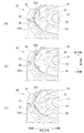
- FIG. 4 is a view showing the flow of oil at the oil passage port (second oil passage port 322) of the piston body 30.
- the oil flowing out from the second oil passage port 322 of the first pressure side oil passage 32 tends to flow outward in the radial direction as shown in FIG.
- the second oil passage port 322 is separated from the extending portion 35 in the radial direction, the disturbance of the flow and the stay due to the oil hitting the extending portion 35 are suppressed. Therefore, the oil flowing out from the second oil passage port 322 can flow smoothly to the pressure side first valve 41 side and the orifice 41f.
- the shape of the edge part of the radial direction outer side of the extension part 35 is formed in curve shape. Therefore, the occurrence of turbulence and stagnation in the oil flow around the end of the extension 35 is further suppressed.
- FIG. 5 is a view showing the piston body 230 of the second embodiment.
- 5A is a top view of the piston body 230 viewed from the other side
- FIG. 5B is a cross-sectional view of the piston body 230 shown in FIG. 5A, taken along line Vb-Vb
- FIG. It is the fragmentary perspective view which looked at the piston body 230 from the other side.
- the same components as those in the first embodiment described above are denoted by the same reference numerals, and detailed description thereof is omitted.
- the piston body 230 of the second embodiment includes a through hole 31, a first pressure side oil passage 32, a first extension side oil passage 33, an inner annular portion 34, It has the extension part 35, the outer side annular part 36, the one side inner side annular part 37, the one side outer side annular part 38, and the protrusion part 239 provided in the other side. That is, the piston body 230 of the second embodiment is different from the other embodiments in that it has a protrusion 239.
- the protruding portion 239 is disposed on the radially outer side than the extending portion 35.
- the projecting portion 239 is formed to extend from the outside of the extending portion 35 to the outer annular portion 36 in the radial direction.
- the protrusion part 239 is located between the 2nd 2nd oil-path ports 322 where at least one part in radial direction adjoins the circumferential direction.
- the protruding portion 239 protrudes from the other end surface 30 ⁇ / b> A and has a protruding height lower than that of the extending portion 35.
- the protruding portion 239 is formed from the outside of the extending portion 35 to the second oil passage port 322 of the first pressure side oil passage 32 in the radial direction of the piston body 230, and has a lower protruding height than the extending portion 35. It is formed.
- the second oil passage port 322 is separated from the extending part 35 in the radial direction, so that the flow is disturbed and stays due to the oil hitting the extending part 35. It is suppressed. Therefore, variation in damping force generated in the hydraulic shock absorber 1 can be reduced.
- the protrusion 239 is positioned around the outer annular portion 36 and is positioned between the adjacent second oil passage ports 322 in the circumferential direction, thereby suppressing interference of oil flowing through the adjacent second oil passage ports 322. To do. Therefore, the oil that has flowed out of the second oil passage port 322 can smoothly flow toward the pressure side first valve 41, and the variation in the damping force generated in the hydraulic shock absorber 1 can be further reduced.
- FIG. 6 is a view showing a modified example (modified example 1) of the piston body 230 of the second embodiment.
- the protruding height of the extending portion 35 may be formed lower than the inner annular portion 34.
- the extending portion 35 is provided at the other side of the extending portion 35 by forming the protruding height of the extending portion 35 lower than the inner annular portion 34.
- a gap is formed between the compression side first valve 41 (see FIG. 2B).
- the piston body 230 of 2nd Embodiment may form the notch part 35S dented toward the one side of an axial direction in the extension part 35, as shown in FIG.6 (b).
- the notch 35S is formed inside the extension 35 in the radial direction. That is, the notch 35S is formed between the inner annular portion 34 and the extending portion 35 in the radial direction.
- a notch portion disposed on a side relatively far from the second oil passage port 322 in the radial direction in a state where the pressure side first valve 41 is provided on the other side.
- the flow of oil in the circumferential direction is further promoted by 35S.
- oil pressure can be uniformly applied in the circumferential direction to the pressure side first valve 41 (see FIG. 2B), and variations in the damping force generated in the hydraulic shock absorber 1 can be achieved. Can be further reduced.
- the height of the protrusion part 239 is not limited to the height shown, for example in FIG.
- the extension portion 35 may be formed to be approximately half the height in the axial direction relative to the protruding height in the axial direction.
- FIG. 7 is a diagram illustrating a piston body 330 according to the third embodiment.
- FIG. 7A is a top view of the piston body 330 as viewed from the other side
- FIG. 7B is a sectional view taken along the line VIIb-VIIb of the piston body 330 shown in FIG. 7A
- FIG. It is the fragmentary perspective view which looked at the piston body 330 from the other side.
- the same components as those of the other embodiments described above are denoted by the same reference numerals, and detailed description thereof is omitted.
- the piston body 330 of the third embodiment includes a through hole 31, a first pressure side oil passage 32, a first extension side oil passage 33, an inner annular portion 34, An extending portion 335, an outer annular portion 36, a first inner annular portion 37, and a first outer annular portion 38 are provided on the other side. That is, in the piston body 330 of the third embodiment, the configuration of the extending portion 335 is different from that of the other embodiments.
- oil flows along with the relative movement of the piston rod 21 (rod) (see FIG. 1) with respect to the first cylinder 11 (cylinder) (see FIG. 1).
- a piston body 330 (flow path forming portion) in which a flowing first pressure side oil passage 32 (flow passage) is formed, and a first pressure side valve portion 40 (valve) that opens and closes the first pressure side oil passage 32 of the piston body 330 (FIG.
- an inner annular portion 34 annular projecting portion that is formed in an annular shape and projects in the axial direction of the piston body 330 from the piston body 330 toward the first pressure side valve portion 40, and in the radial direction of the piston body 330
- An extending portion 335 that extends further outward from the outer side of the inner annular portion 34 and that has a protruding height from the piston body 330 lower than that of the inner annular portion 34 is provided.
- the extending portion 335 is provided to extend radially outward on the outer periphery of the inner annular portion 34.
- the extending portion 335 is formed to extend to the outer annular portion 36 (outer annular protruding portion).
- a plurality (eight in this embodiment) of extending portions 335 are provided in the circumferential direction.
- at least one part in the radial direction is formed between the 2nd 2nd oil-path ports 322 which the extending part 335 adjoins in the circumferential direction.
- the extending portion 335 protrudes toward the other side in the axial direction, as shown in FIG.
- the protruding height of the extending portion 335 is set to be lower than the inner annular portion 34.
- the protrusion height of the extension part 335 is formed lower than the inner side annular part 34, and the sticking of the compression side 1st valve
- FIG. 8 is a view showing a modified example (modified example 2) of the piston body 330 of the third embodiment.
- the extending portion 335 is provided to extend in the circumferential direction, and has a notch portion 335 ⁇ / b> S that is recessed toward one side in the axial direction. May be.
- the oil in the circumferential direction is cut by the notch 335S in a state where the pressure side first valve 41 (see FIG. 2B) is provided on the other side. Distribution is promoted. As a result, the piston body 330 can uniformly apply oil pressure to the pressure side first valve 41 in the circumferential direction.
- the extending portion 3335 extends from the inner annular portion 34 to the inner side of the second oil passage port 322 of the first pressure side oil passage 32 in the radial direction. You may form so that it may extend. That is, the extending portion 3335 is formed away from the outer annular portion 36. In the example shown in FIG. 8B, the shape of the end portion of the extending portion 3335 on the radially outer side is formed with a corner. In the piston body 330 of the modified example shown in FIG. 8B, the second oil passage port 322 is separated from the extending portion 3335 in the radial direction, so that the flow is disturbed and stays due to the oil hitting the extending portion 3335. It is suppressed. Therefore, it is possible to further reduce the variation in damping force generated in the hydraulic shock absorber 1.
- the protruding height of the extending portion 335a is formed to be the same as the protruding height of the inner annular portion 34 from the inner side to the outer side in the radial direction. However, a part of the outer side in the radial direction may be formed lower than the inner annular part 34. In the example shown in FIG. 8C, the protruding height of the extending portion 335 a is formed such that the portion where the second oil passage port 322 is formed in the radial direction is lower than the protruding height of the inner annular portion 34. In the piston body 330 of the modified example shown in FIG. 8C configured as described above, it is possible to further reduce variation in damping force generated in the hydraulic shock absorber 1.
- FIG. 9 is a view showing a piston body 430 of the fourth embodiment.
- FIG. 9A is a top view of the piston body 430 viewed from the other side
- FIG. 9B is a cross-sectional view of the piston body 430 shown in FIG. 9A
- FIG. It is the fragmentary perspective view which looked at the piston body 430 from the other side.
- the same components as those in the other embodiments described above are denoted by the same reference numerals, and detailed description thereof is omitted.
- the piston body 430 of the fourth embodiment has a through hole 31, a first pressure side oil passage 32, a first extension side oil passage 33, an inner annular portion 34, and an extension provided on the other side. It has a portion 435, an outer annular portion 36, one side inner annular portion 37, and one side outer annular portion 38.
- the structure of the extension part 435 differs from other embodiment.
- the extending portion 435 is provided to extend outward in the radial direction outside the inner annular portion 34.
- a plurality (eight in this embodiment) of extending portions 435 are provided in the circumferential direction.
- the shape of the edge part in the radial direction outer side of the extension part 435 is formed in the curve shape which protrudes outside as shown to Fig.9 (a).
- the extending portion 435 is formed so as to extend inward from the second oil passage port 322 in the radial direction.
- each extending portion 435 is alternately arranged with the second oil passage port 322 in the circumferential direction.
- each extending portion 435 has a notch 435 ⁇ / b> S that is recessed in the axial direction of the piston body 430 and extends in the circumferential direction of the piston body 430.
- the cutout portion 435 ⁇ / b> S is formed to be recessed to the middle of the height of the extension portion 435 in the axial direction.
- the protruding height of the extending portion 435 may be formed higher than the protruding height of the inner annular portion 34.
- the second oil passage port 322 is separated from the extending portion 435 in the radial direction, so that the flow is disturbed and stays due to the oil hitting the extending portion 435. It is suppressed. Therefore, it is possible to further reduce the variation in damping force generated in the hydraulic shock absorber 1. Furthermore, in the piston body 430 of the fourth embodiment, the circulation of oil in the circumferential direction is further promoted by the notch portion 435S in a state where the pressure side first valve 41 (see FIG. 2B) is provided on the other side. The As a result, in the piston body 430, oil pressure can be uniformly applied to the pressure side first valve 41 in the circumferential direction, and variation in the damping force generated in the hydraulic shock absorber 1 can be further reduced. Become.
- FIG. 10 is a view showing a modified example (modified example 3) of the piston body 430 of the fourth embodiment.
- the protruding height of the extending portion 435 may be formed lower than the inner annular portion 34.
- the protruding height of the extending portion 435 is formed lower than that of the inner annular portion 34, so that the compression side first valve 41 with respect to the extending portion 435 (FIG. 2B). Reference) is suppressed, and the operation of the pressure side first valve 41 is stabilized. As a result, it is possible to reduce variations in the generated damping force.
- the piston body 430 of the fourth embodiment may be formed such that the depth in the axial direction of the notch 435S is the same as the protruding height of the extension 435, as shown in FIG. 10 (b). . That is, the notch 435S may be formed up to the other end surface 30A.
- the circumferential direction is provided by the notch 435S formed relatively deep in a state where the pressure side first valve 41 (see FIG. 2B) is provided on the other side.
- the oil distribution in is promoted more.
- oil pressure can be uniformly applied to the pressure side first valve 41 in the circumferential direction, and variation in the damping force generated in the hydraulic shock absorber 1 can be further reduced. Become.
- the piston body 430 of the fourth embodiment may have a plurality of notches in the radial direction of each extending portion 435, as shown in FIG.
- the second cutout portion 4435S may be formed outside the cutout portion 435S in the radial direction outside the cutout portion 435S.
- the circumferential direction is formed by the notch 435S and the second notch 4435S in a state where the pressure side first valve 41 (see FIG. 2B) is provided on the other side.
- the oil distribution in is promoted more.
- oil pressure can be uniformly applied to the pressure side first valve 41 in the circumferential direction, and variation in the damping force generated in the hydraulic shock absorber 1 can be further reduced. Become.
- FIG. 11 is a diagram illustrating a piston body 530 according to the fifth embodiment.
- FIG. 11A is a top view of the piston body 530 viewed from the other side
- FIG. 11B is a cross-sectional view of the piston body 530 shown in FIG. 11A
- FIG. It is the fragmentary perspective view which looked at the piston body 530 from the other side.
- the same components as those in the other embodiments described above are denoted by the same reference numerals, and detailed description thereof is omitted.
- the piston body 530 of the fifth embodiment includes a through hole 31, a first pressure side oil passage 32, a first extension side oil passage 33, an inner annular portion 34, an extension portion 535, and an outer annular shape. It has a portion 36, one side inner annular portion 37 and one side outer annular portion 38. That is, in the piston body 530 of the fifth embodiment, the configuration of the extending portion 535 is different from that of the other embodiments.
- the extending portion 535 is provided to extend outward in the radial direction outside the inner annular portion 34.
- a plurality (eight in this embodiment) of extending portions 535 are provided in the circumferential direction.
- the shape of the edge part in the radial direction outer side of the extension part 535 is formed in the curve shape which protrudes outside as shown to Fig.11 (a).
- the extending portion 535 is formed so as to extend inward from the second oil passage port 322 in the radial direction.
- each extending portion 535 is alternately arranged with the second oil passage port 322 in the circumferential direction.
- the extending part 535 protrudes in the axial direction toward the other side, as shown in FIGS. 11 (b) and 11 (c).
- the extending portion 535 is formed such that the protruding height in the axial direction of the piston body 530 is lower than that of the inner annular portion 34.
- the second oil passage port 322 is separated from the extending portion 535 in the radial direction, so that the flow is disturbed and stays due to the oil hitting the extending portion 535. It is suppressed. Therefore, it is possible to further reduce the variation in damping force generated in the hydraulic shock absorber 1. Furthermore, the protrusion height of the extending portion 535 is formed lower than that of the inner annular portion 34, whereby sticking of the pressure side first valve 41 (see FIG. 2B) to the extending portion 535 is suppressed, and the pressure side first The operation of the valve 41 is stabilized. As a result, it is possible to further reduce variations in the generated damping force.
- FIG. 12A is a view showing a piston body 630 of the sixth embodiment
- FIG. 12B is a view showing a piston body 730 of the seventh embodiment
- 12 (a) and 12 (b) show top views of the piston bodies (630, 730) as viewed from the other side.
- the same components as those in the other embodiments described above are denoted by the same reference numerals, and detailed description thereof is omitted.
- the piston body 630 of the sixth embodiment includes a through hole 31, a first pressure side oil passage 632, a first extension side oil passage 633, an inner annular portion 34, an extension portion 635, and an outer annular shape.
- a portion 36 is provided.
- the piston body 630 of the sixth embodiment has the same basic configuration as the piston body 630 of the first embodiment.
- the shapes of the first pressure side oil passage 632 and the first extension side oil passage 633 are different from the first pressure side oil passage 32 and the first extension side oil passage 33 of the piston body 30 of the first embodiment.
- the second oil passage port 6322 facing the first oil chamber Y1 (see FIG. 1) of the first pressure side oil passage 632 is formed in a circular shape as shown in FIG.
- the fourth oil passage port 6334 facing the second oil chamber Y2 (see FIG. 1) of the first extension side oil passage 633 is formed in a rectangular shape as shown in FIG.
- the extending portion 635 is provided so as to extend outward in the radial direction outside the inner annular portion 34.
- a plurality of the extending portions 635 are provided in the circumferential direction (five in this embodiment).
- the shape of the edge part in the radial direction outer side of the extension part 635 is formed in the rectangular shape, as shown to Fig.12 (a).
- the extending portion 635 is formed to extend to the inner side of the second oil passage port 6322 in the radial direction. Further, each extending portion 635 is alternately arranged with the second oil passage port 6322 in the circumferential direction.
- the protruding height of the extending portion 635 may be the same as the protruding height of the inner annular portion 34 or higher than the protruding height of the inner annular portion 34. Further, the extending portion 635 may have a cutout portion that extends in the circumferential direction and is recessed in the axial direction.
- the piston body 730 of the seventh embodiment includes a through hole 31, a first pressure side oil passage 632, a first extension side oil passage 633, an inner annular portion 34, an extension portion 735, and an outer annular shape.
- a portion 36 is provided.
- the extending portion 735 is provided to extend radially outward on the outer periphery of the inner annular portion 34. Further, the extending portion 735 is formed up to the outer annular portion 36. Accordingly, in the piston body 730 of the seventh embodiment, as shown in FIG.
- each extending portion 735 has at least a portion in the radial direction between the two second oil passage ports 6322 adjacent in the circumferential direction. Formed.
- the extending part 735 protrudes toward the other side in the axial direction.
- the protruding height of the extending portion 735 is set to be lower than the inner annular portion 34.
- the protruding height of the extending portion 735 is formed to be lower than that of the inner annular portion 34, whereby the compression-side first valve 41 (FIG. 2) with respect to the extending portion 735 is formed. (B) is suppressed, and the operation of the pressure side first valve 41 is stabilized. As a result, it is possible to reduce variations in the generated damping force.
- the protruding height of the extending portion 735 may be formed higher than the protruding height of the inner annular portion 34. Further, the extending portion 735 may have a cutout portion extending in the circumferential direction and recessed in the axial direction.
- FIG. 13 is a partial cross-sectional view of the piston body 830 of the eighth embodiment.
- the piston body 830 of the seventh embodiment has the same basic configuration as the piston body 30 of the first embodiment described above.
- the piston body 830 of the eighth embodiment is different from the other embodiments in the configuration of the extending portion 835. Specifically, the extension height of the extending portion 835 changes from the inner side to the outer side in the radial direction.
- the height of the extending portion 835 is equal to or higher than the protruding height of the inner annular portion 34. Further, the extending portion 835 is formed so that the protruding height gradually increases from the inner side toward the outer side in the radial direction.
- the second oil passage port 322 is separated from the extending portion 835 in the radial direction, so that the turbulence or stagnation due to the oil hitting the extending portion 835 is retained. Is suppressed. For this reason, it is possible to reduce variations in the damping force generated in the hydraulic shock absorber 1.
- FIG. 14 is a diagram illustrating the hydraulic shock absorber 1 according to the fourth to sixth modifications.
- FIG. 14A shows a hydraulic shock absorber 1 according to Modification 4 of the first embodiment
- FIG. 14B shows a hydraulic shock absorber 1 according to Modification 5 of the first embodiment
- FIG. The hydraulic shock absorber 1 of the modification 6 of 1st Embodiment is shown.
- the basic configurations of the hydraulic shock absorbers 1 of Modification 4 to Modification 6 are the same as those of the first embodiment described above. However, the configuration of the first pressure side valve portion (440, 540, 640) is different from that of the first pressure side valve portion 40 of the first embodiment.
- the first pressure side valve portion 440 of Modification 4 is formed such that the outer diameter of the pressure side first valve 441 is larger than the outer diameter of the outer annular portion 36. Further, the pressure side second valve 442 is formed so that the outer diameter is larger than the outer diameter of the extending portion 35. That is, the pressure-side second valve 442 is not formed on the extending portion 35.
- the first pressure side valve portion 540 of Modification 5 is formed such that the outer diameter of the pressure side first valve 541 is larger than the outer diameter of the outer annular portion 36.
- the pressure side second valve 542 is formed to have the same outer diameter as the pressure side first valve 541.
- the first pressure side valve portion 640 of Modification 6 is formed such that the outer diameter of the pressure side first valve 641 is larger than the outer diameter of the outer annular portion 36.
- the pressure side second valve 642 is formed to be larger than the outer diameter of the pressure side first valve 641.
- the second oil passage port 322 is separated from the extending part 35 in the radial direction. Disturbances and stagnation of the flow due to hitting are suppressed. For this reason, it is possible to reduce variations in the damping force generated in the hydraulic shock absorber 1.
- FIG. 15 is a diagram illustrating the hydraulic shock absorber 1 according to the seventh to ninth modifications.
- FIG. 15A shows a hydraulic shock absorber 1 according to Modification 7 of the first embodiment
- FIG. 15B shows a hydraulic shock absorber 1 according to Modification 8 of the first embodiment
- FIG. The hydraulic shock absorber 1 of the modification 9 of 1st Embodiment is shown.
- the extended portion 35 has a rectangular shape in which the shape of the end portion on the radially outer side of the extended portion 35 has a corner in a plan view as viewed from the other side. Formed. Moreover, as for the external shape of the side part of the extension part 35, one side is formed larger compared with the other side. That is, the extending part 35 is formed in a taper shape in the axial direction. Thus, you may form like the modification 7 about the shape of the extension part 35 of 1st Embodiment.
- the extended portion 35 has a radially outward end shape in the radial direction when viewed from the other side. It is formed in a curved shape that is convex toward the surface. Moreover, the external shape of the side part of the extension part 35 is formed equally from the other side to one side. Thus, you may form like the modification 8 about the shape of the extension part 35 of 1st Embodiment.
- the extended portion 35 has a radially outward end shape in the radial direction when viewed from the other side. It is formed in a curved shape that is convex toward the surface. Moreover, as for the external shape of the side part of the extension part 35, one side is formed larger compared with the other side. That is, the extending part 35 is formed in a taper shape in the axial direction. Thus, you may form like the modification 9 about the shape of the extension part 35 of 1st Embodiment.
- the second oil passage port 322 is separated from the extending part 35 in the radial direction, so that the turbulence or stagnation due to the oil hitting the extending part 35 is retained. Is suppressed, and variation in damping force generated in the hydraulic shock absorber 1 can be reduced.
- Modification 8 and Modification 9 since the shape of the end portion of the extending portion 35 on the radially outer side is formed in a curved shape, the oil flow around the end portion of the extending portion 35 is disturbed. The occurrence of stagnation is further suppressed.
- the extending portion 35 is formed only on the other side, but the extending portion 35 may be formed not only on the other side but also on the one side.
- the hydraulic shock absorbers 1 of other embodiments may be applied to the bottom piston body 61.
- the hydraulic shock absorber 1 in the above-described embodiment is a so-called double pipe hydraulic shock absorber 1, but the present invention is a first cylinder that is arranged in order from the inner side to the outer side in the radial direction around the axis.
- the so-called triple pipe hydraulic shock absorber 1 including the second cylinder and the “third cylinder” may be used.
- SYMBOLS 1 Hydraulic shock absorber, 11 ... 1st cylinder, 21 ... Piston rod, 30 ... Piston body, 32 ... 1st pressure side oil path, 33 ... 1st extension side oil path, 34 ... Inner ring part, 35 ... Extension part, 35S ... Notch part, 36 ... Outer annular part, 40 ... First pressure side valve part, 41 ... Pressure side first valve, 42 ... Pressure side second valve, 43 ... Pressure side third valve, 44 ... Ring seat, 50 ... First extension Side valve
Landscapes
- Engineering & Computer Science (AREA)
- General Engineering & Computer Science (AREA)
- Mechanical Engineering (AREA)
- Physics & Mathematics (AREA)
- Fluid Mechanics (AREA)
- Fluid-Damping Devices (AREA)
Abstract
Description
本構成により、半径方向において流路の油路口と延部とが離れていることによって、流体が延部に当たることによる流れの乱れや滞留が抑制される。この結果、圧力緩衝装置において発生させる減衰力のバラツキを抑制することができる。
本構成により、延部に対するバルブの貼り付きが抑制され、バルブの動作が安定する。この結果、圧力緩衝装置において発生させる減衰力のバラツキを抑制することができる。
<第1実施形態>
図1は、第1実施形態の油圧緩衝装置1の全体構成図である。
なお、以下の説明において、図1に示す油圧緩衝装置1の長手方向を「軸方向」と称する。また、軸方向において、油圧緩衝装置1の下側を「一方側」と称し、油圧緩衝装置1の上側を「他方側」と称して説明を行う。また、図1に示す油圧緩衝装置1の左右方向を「半径方向」と称し、中心軸側を「内側」、中心軸に対して離れる側を「外側」と称する。
まず、第1実施形態の油圧緩衝装置1の構成について説明する。
第1実施形態の油圧緩衝装置1は、図1に示すように、オイルを収容する第1シリンダ11と、第2シリンダ12と、一部が第1シリンダ11の内部に入り、軸方向に移動可能なピストンロッド21と、ピストンロッド21に固定され、第1シリンダ11の内側を移動するピストン部100と、第1シリンダ11の一方側の底部に設けられたボトムバルブ部60を有する。
油圧緩衝装置1は、図1に示すように、半径方向の内側から外側に向けて順に第1シリンダ11と第2シリンダ12とを備える、いわゆる二重管の構造である。
第1シリンダ11の一方側の端部(底部)は、ボトムバルブ部60によって塞がれている。また、第2シリンダ12の一方側の端部は底蓋13によって塞がれている。一方、第1シリンダ11および第2シリンダ12の他方側の端部(上部)は、ロッドガイド14、オイルシール15およびキャップ16によって、ピストンロッド21が通過可能に塞がれている。また、第1シリンダ11と第2シリンダ12との間には、円筒状の空間であるリザーバ室Rが形成されている。リザーバ室Rには、オイルが収容されているとともに、リザーバ室Rの他方側にはガスが封入されている。
ピストンロッド21は、図1に示すように、一方側における一部が第1シリンダ11の内部に入り、他方側における残りの一部が第1シリンダ11の外部に露出し、軸方向に沿って移動可能とされている。また、ピストンロッド21は、一方側の端部にピストン部100を備えている。そして、ピストンロッド21とピストン部100とは、軸方向に一体的に移動する。また、ピストン部100は、シリンダの内周面に沿って軸方向に移動可能に設けられている。
ピストン部100は、図1に示すように、軸方向に貫通する複数の油路(後述)が形成されたピストンボディ30と、ピストンボディ30の他方側に設けられた第1圧側バルブ部40と、ピストンボディ30の一方側に設けられた第1伸側バルブ部50とを備えている。そして、ピストン部100は、第1シリンダ11の内側の空間を、軸方向における一方側(図1の下側)の空間である第1油室Y1と、軸方向における他方側(図1の上側)の空間である第2油室Y2とに区画している。
ボトムバルブ部60は、図1に示すように、油圧緩衝装置1の一方側の端部に設けられ、リザーバ室Rと第1油室Y1とを区分する。ボトムバルブ部60は、軸方向に貫通する複数の油路61Rが形成されたボトムピストンボディ61と、ボトムピストンボディ61の他方側(第1油室Y1側)に設けられる第2伸側バルブ部622と、ボトムピストンボディ61の一方側(リザーバ室R側)に設けられる第2圧側バルブ部621とを備えている。
図2は、第1実施形態のピストンボディ30を示す図である。
図2(a)はピストンボディ30を他方側からみた上面図であり、図2(b)は図2(a)に示すピストンボディ30のIIb-IIb断面図であり、図2(c)はピストンボディ30を他方側からみた部分斜視図である。なお、図2(b)ではピストンロッド21および第1圧側バルブ部40および第1伸側バルブ部50を併せて図示している。
そして、ピストン部100は、ピストンロッド21の第1シリンダ11に対する相対的な移動に伴ってオイルが流れる第1圧側油路32(流路)が形成されるピストンボディ30(流路形成部)と、ピストンボディ30の第1圧側油路32を開閉する第1圧側バルブ部40(バルブ)と、環状に形成され、ピストンボディ30から第1圧側バルブ部40に向けてピストンボディ30の軸方向に突出する内側環状部34(環状突出部)と、ピストンボディ30の半径方向において内側環状部34の外側から第1圧側油路32の第2油路口322よりも内側に延び、ピストンボディ30から第1圧側バルブ部40に向けて軸方向に突出する延部35とを有する。
以下で、各構成部について詳述する。
ピストンボディ30は、図2(a)および図2(b)に示すように、軸方向に延びる貫通孔31と、ピストンボディ30内に形成される第1圧側油路32および第1伸側油路33と、他方側に設けられる内側環状部34と、他方側であって内側環状部34の半径方向外側に設けられる延部35と、他方側であって延部35のさらに半径方向外側に設けられる外側環状部36とを有する。
また、ピストンボディ30は、図2(b)に示すように、一方側に設けられる一方側内側環状部37と、一方側であって一方側内側環状部37のさらに半径方向外側に設けられる一方側外側環状部38とを有する。
各第2油路口322は、図2(a)に示すように、略矩形状に形成される。そして、各第2油路口322は、周方向において隣接する2本の延部35の間ではなく、半径方向において延部35よりも外側に配置される。
また、各第4油路口334は、図2(a)に示すように、略円形状に形成される。そして、各第4油路口334は、半径方向において第1圧側油路32の第2油路口322の外側に配置される。
第1圧側バルブ部40は、図2(b)に示すように、最も一方側に配置される圧側第1バルブ41と、圧側第1バルブ41の他方側に配置される圧側第2バルブ42と、圧側第2バルブ42の他方側に配置される圧側第3バルブ43と、圧側第3バルブ43の他方側に配置される環座44と、環座44の他方側に設けられるバルブストッパ45とを有する。
さらに、圧側第3バルブ43は、外径が延部35上に位置するように形成される。そして、環座44は、外径が内側環状部34の外径よりも小さく形成される。
第1伸側バルブ部50は、最も他方側に配置される伸側第1バルブ51と、伸側第1バルブ51の一方側に配置される伸側第2バルブ52と、伸側第2バルブ52の一方側に配置される伸側第3バルブ53と、伸側第3バルブ53の一方側に配置される環座54と、環座54の一方側に設けられるバルブストッパ55とを有する。
次に、第1実施形態に係る油圧緩衝装置1の作用および効果について説明する。
図3は、第1実施形態の油圧緩衝装置1のピストン部100におけるオイルの流れを示す図である。なお、図3(a)は圧縮行程時におけるオイルの流れを示し、図3(b)は伸張行程時におけるオイルの流れを示す。
油圧緩衝装置1の圧縮行程時においては、ピストンロッド21が第1シリンダ11に対して軸方向の一方側(図1の下側)へ移動する。ピストンロッド21に固定されたピストン部100は、第1油室Y1内のオイルを圧縮し、第1油室Y1の圧力を上昇させる。
また、リザーバ室R内のオイルは、図1に示すように、ボトムピストンボディ61の油路61Rを閉塞する第2伸側バルブ部622を開いて第1油室Y1内に流入する。
そして、オイルが油路(第1伸側油路33,油路61R)およびバルブ(第1伸側バルブ部50,第2伸側バルブ部622)を流れる際に生じる抵抗により、油圧緩衝装置1は伸張行程時における減衰力を発生させる。
次に、ピストンボディ30の作用および効果について説明する。
図4は、ピストンボディ30の油路口(第2油路口322)におけるオイルの流れを示す図である。
ピストン部100において、第1圧側油路32の第2油路口322から流れ出るオイルは、図4に示すように、半径方向の外側に流れようとする。このとき、半径方向において第2油路口322が延部35から離れていることによって、オイルが延部35に当たることによる流れの乱れや滞留が抑制される。従って、第2油路口322から流れ出るオイルを、圧側第1バルブ41側やオリフィス41fへとスムーズに流すことができる。その結果、油圧緩衝装置1において発生させる減衰力のバラツキを低減することが可能になる。
また、第1実施形態においては、延部35の半径方向外側の端部の形状が曲線状に形成されている。そのため、延部35の端部周辺におけるオイルの流れに乱れや滞留が発生することがさらに抑制される。
続いて、第2実施形態の油圧緩衝装置1について説明する。
図5は、第2実施形態のピストンボディ230を示す図である。
図5(a)はピストンボディ230を他方側からみた上面図であり、図5(b)は図5(a)に示すピストンボディ230のVb-Vb断面図であり、図5(c)はピストンボディ230を他方側からみた部分斜視図である。
なお、第2実施形態の説明において、上述した第1実施形態と同様な構成部については同一の符号を付してその詳細な説明を省略する。
また、突出部239は、図5(b)に示すように、他方側の端部面30Aから突出し、突出高さが延部35のよりも低く形成される。
すなわち、突出部239は、ピストンボディ230の半径方向において延部35の外側から第1圧側油路32の第2油路口322の間に向けて形成され、延部35よりも突出高さが低く形成される。
さらに、突出部239は、外側環状部36の周辺に位置するとともに、周方向において隣接する第2油路口322の間に位置することによって、隣接する第2油路口322を流れるオイルの干渉を抑制する。従って、第2油路口322を流れ出たオイルが圧側第1バルブ41側へとスムーズに流れることができ、油圧緩衝装置1において発生させる減衰力のバラツキをより低減することが可能になる。
図6は、第2実施形態のピストンボディ230の変形例(変形例1)を示す図である。
第2実施形態のピストンボディ230では、図6(a)に示すように、延部35の突出高さを内側環状部34よりも低く形成しても良い。
図6(a)に示す変形例のピストンボディ230では、延部35の突出高さが内側環状部34よりも低く形成されることによって、延部35と、延部35の他方側に設けられる圧側第1バルブ41(図2(b)参照)との間に隙間が形成される。そして、延部35と圧側第1バルブ41との間に隙間にオイルが入り込むことによって、延部35に対する圧側第1バルブ41の貼り付きが抑制され、圧側第1バルブ41の動作が安定する。その結果、油圧緩衝装置1において発生させる減衰力のバラツキをさらに低減することが可能になる。
図6(b)に示す変形例のピストンボディ230では、他方側に圧側第1バルブ41が設けられた状態にて、半径方向において第2油路口322から比較的遠い側に配置される切欠部35Sによって周方向におけるオイルの流通がより促進される。その結果、ピストンボディ230では、圧側第1バルブ41(図2(b)参照)に対して周方向において均一にオイルの圧力を付与することができ、油圧緩衝装置1において発生させる減衰力のバラツキをより低減することが可能になる。
このように構成される図6(c)に示す変形例のピストンボディ230では、油圧緩衝装置1において発生させる減衰力のバラツキをより低減することが可能になる。
続いて、第3実施形態の油圧緩衝装置1について説明する。
図7は、第3実施形態のピストンボディ330を示す図である。
図7(a)はピストンボディ330を他方側からみた上面図であり、図7(b)は図7(a)に示すピストンボディ330のVIIb-VIIb断面図であり、図7(c)はピストンボディ330を他方側からみた部分斜視図である。
なお、第3実施形態の説明において、上述した他の実施形態と同様な構成部については同一の符号を付してその詳細な説明を省略する。
また、延部335は、図7(b)に示すように、軸方向の他方側に向けて突出する。本実施形態では、延部335の突出高さは、内側環状部34よりも低くなるように設定している。
図8は、第3実施形態のピストンボディ330の変形例(変形例2)を示す図である。
第3実施形態のピストンボディ330において、図8(a)に示すように、延部335は、周方向に延びて設けられるとともに、軸方向の一方側に向けて凹む切欠部335Sを有していても良い。
そして、図8(a)に示す変形例のピストンボディ330では、他方側に圧側第1バルブ41(図2(b)参照)が設けられた状態にて、切欠部335Sによって周方向におけるオイルの流通が促進される。その結果、ピストンボディ330では、圧側第1バルブ41に対して周方向において均一にオイルの圧力を付与することができる。
そして、図8(b)に示す変形例のピストンボディ330では、半径方向において第2油路口322が延部3335から離れていることによって、オイルが延部3335に当たることによる流れの乱れや滞留が抑制される。そのため、油圧緩衝装置1において発生させる減衰力のバラツキをより低減することが可能になる。
このように構成される図8(c)に示す変形例のピストンボディ330では、油圧緩衝装置1において発生させる減衰力のバラツキをより低減することが可能になる。
続いて、第4実施形態の油圧緩衝装置1について説明する。
図9は、第4実施形態のピストンボディ430を示す図である。
図9(a)はピストンボディ430を他方側からみた上面図であり、図9(b)は図9(a)に示すピストンボディ430のIXb-IXb断面図であり、図9(c)はピストンボディ430を他方側からみた部分斜視図である。
なお、第4実施形態の説明において、上述した他の実施形態と同様な構成部については同一の符号を付してその詳細な説明を省略する。
さらに、第4実施形態のピストンボディ430では、他方側に圧側第1バルブ41(図2(b)参照)が設けられた状態にて、切欠部435Sによって周方向におけるオイルの流通がより促進される。その結果、ピストンボディ430では、圧側第1バルブ41に対して周方向において均一にオイルの圧力を付与することができ、油圧緩衝装置1において発生させる減衰力のバラツキをより低減することが可能になる。
図10は、第4実施形態のピストンボディ430の変形例(変形例3)を示す図である。
第4実施形態のピストンボディ430では、図10(a)に示すように、延部435の突出高さは、内側環状部34よりも低く形成しても良い。
そして、図10(a)に示すピストンボディ430では、延部435の突出高さが内側環状部34よりも低く形成されることによって、延部435に対する圧側第1バルブ41(図2(b)参照)の貼り付きが抑制され、圧側第1バルブ41の動作が安定する。その結果として、発生させる減衰力のバラツキを低減することが可能になる。
そして、図10(b)に示すピストンボディ430では、他方側に圧側第1バルブ41(図2(b)参照)が設けられた状態にて、比較的深く形成される切欠部435Sによって周方向におけるオイルの流通がより促進される。その結果、ピストンボディ430では、圧側第1バルブ41に対して周方向において均一にオイルの圧力を付与することができ、油圧緩衝装置1において発生させる減衰力のバラツキをより低減することが可能になる。
そして、図10(c)に示すピストンボディ430では、他方側に圧側第1バルブ41(図2(b)参照)が設けられた状態にて、切欠部435Sおよび第2切欠部4435Sによって周方向におけるオイルの流通がより促進される。その結果、ピストンボディ430では、圧側第1バルブ41に対して周方向において均一にオイルの圧力を付与することができ、油圧緩衝装置1において発生させる減衰力のバラツキをより低減することが可能になる。
続いて、第5実施形態の油圧緩衝装置1について説明する。
図11は、第5実施形態のピストンボディ530を示す図である。
図11(a)はピストンボディ530を他方側からみた上面図であり、図11(b)は図11(a)に示すピストンボディ530のXIb-XIb断面図であり、図11(c)はピストンボディ530を他方側からみた部分斜視図である。
なお、第5実施形態の説明において、上述した他の実施形態と同様な構成部については同一の符号を付してその詳細な説明を省略する。
さらに、延部535の突出高さが内側環状部34よりも低く形成されることによって、延部535に対する圧側第1バルブ41(図2(b)参照)の貼り付きが抑制され、圧側第1バルブ41の動作が安定する。その結果として、発生させる減衰力のバラツキをさらに低減することが可能になる。
続いて、第6実施形態の油圧緩衝装置1について説明する。
図12(a)は第6実施形態のピストンボディ630を示す図であり、図12(b)は第7実施形態のピストンボディ730を示す図である。
図12(a)および図12(b)では、ピストンボディ(630,730)を他方側からみた上面図を表示している。
なお、第6実施形態および第7実施形態の説明において、上述した他の実施形態と同様な構成部については同一の符号を付してその詳細な説明を省略する。
具体的には、第1圧側油路632の第1油室Y1(図1参照)に対向する第2油路口6322は、図12(a)に示すように、円形状に形成される。また、第1伸側油路633の第2油室Y2(図1参照)に対向する第4油路口6334は、図12(a)に示すように、矩形状に形成される。
第7実施形態のピストンボディ730は、図12(b)に示すように、貫通孔31、第1圧側油路632、第1伸側油路633、内側環状部34、延部735および外側環状部36を有している。
第7実施形態のピストンボディ730では、図12(b)に示すように、延部735は、内側環状部34の外周にて半径方向外側に延びて設けられる。さらに、延部735は、外側環状部36まで形成される。従って、第7実施形態のピストンボディ730では、各延部735は、図12(b)に示すように、半径方向における少なくとも一部が、周方向に隣接する2つの第2油路口6322の間に形成される。
また、延部735は、軸方向の他方側に向けて突出する。本実施形態では、延部735の突出高さは、内側環状部34よりも低くなるように設定している。
続いて、第8実施形態の油圧緩衝装置1について説明する。
図13は、第8実施形態のピストンボディ830の部分断面図である。
なお、第8実施形態の説明において、上述した第1実施形態と同様な構成部については同一の符号を付してその詳細な説明を省略する。
第7実施形態のピストンボディ830は、基本構成は、上述した第1実施形態のピストンボディ30と同様である。ただし、第8実施形態のピストンボディ830は、延部835の構成が他の実施形態と異なる。
具体的には、延部835は、半径方向において内側から外側にかけて突出高さが変化する。第8実施形態では、延部835の高さは、内側環状部34の突出高さ以上にしている。また、延部835は、半径方向において内側から外側に向けて突出高さが次第に高くなるように形成している。
続いて、第1実施形態の油圧緩衝装置1の変形例4~変形例6について説明する。
図14は、変形例4~変形例6の油圧緩衝装置1を示す図である。図14(a)は第1実施形態の変形例4の油圧緩衝装置1を示し、図14(b)は第1実施形態の変形例5の油圧緩衝装置1を示し、図14(c)は第1実施形態の変形例6の油圧緩衝装置1を示す。
次に、第1実施形態の油圧緩衝装置1の変形例7~変形例9について説明する。
図15は、変形例7~変形例9の油圧緩衝装置1を示す図である。図15(a)は第1実施形態の変形例7の油圧緩衝装置1を示し、図15(b)は第1実施形態の変形例8の油圧緩衝装置1を示し、図15(c)は第1実施形態の変形例9の油圧緩衝装置1を示す。
さらに、上述した実施形態におけるピストンボディ(30,230,330,430,530,630,730,830)の構成を、ボトムピストンボディ61に適用しても良い。
Claims (11)
- 流体を収容するシリンダと、
一方側の端部が前記シリンダ内に収容され、他方側の端部が前記シリンダの開口部から突出し、シリンダ軸方向に移動するロッドと、
前記シリンダに対する前記ロッドの相対的な移動において減衰力を発生させる減衰力発生部と、を備え、
前記減衰力発生部は、
前記ロッドの前記シリンダに対する相対的な移動に伴って前記流体が流れる流路が形成される流路形成部と、
前記流路形成部の前記流路を開閉するバルブと、
環状に形成され、前記流路形成部から前記バルブに向けて前記流路形成部の軸方向に突出する環状突出部と、
前記流路形成部の半径方向において前記環状突出部の外側から前記流路の流路口よりも内側に延び、前記流路形成部から前記バルブに向けて前記軸方向に突出する延部と
を有する圧力緩衝装置。 - 前記延部の前記軸方向の突出高さは、前記環状突出部と同一または前記環状突出部より高い請求項1に記載の圧力緩衝装置。
- 前記延部の前記軸方向の突出高さは、前記環状突出部よりも低い請求項1に記載の圧力緩衝装置。
- 前記減衰力発生部は、前記半径方向において前記延部の外側から前記流路の前記流路口の間に向けて形成され、前記延部よりも突出高さが低い突出部を更に備える請求項1に記載の圧力緩衝装置。
- 前記延部は、前記軸方向において凹むとともに前記流路形成部の周方向に延びて形成される切欠部を更に有する請求項1に記載の圧力緩衝装置。
- 前記切欠部は、前記延部の前記軸方向における高さの途中まで凹んで形成される請求項5に記載の圧力緩衝装置。
- 流体を収容するシリンダと、
一方側の端部が前記シリンダ内に収容され、他方側の端部が前記シリンダの開口部から突出し、シリンダ軸方向に移動するロッドと、
前記ロッドの前記シリンダに対する相対的な移動において減衰力を発生させる減衰力発生部と、を備え、
前記減衰力発生部は、
前記シリンダに対する前記ロッドの相対的な移動に伴って前記流体が流れる流路が形成される流路形成部と、
前記流路形成部の前記流路を開閉するバルブと、
環状に形成され、前記流路形成部から前記バルブに向けて前記流路形成部の軸方向に突出する環状突出部と、
前記流路形成部の半径方向において前記環状突出部の外側から更に外側に延び、前記流路形成部からの突出高さが前記環状突出部よりも低く形成される延部と
を有する圧力緩衝装置。 - 環状に形成され、前記半径方向において前記延部の外側にて前記バルブに向けて前記軸方向に突出する外側環状突出部を更に備え、
前記延部は、前記外側環状突出部まで延びて形成される請求項7に記載の圧力緩衝装置。 - 環状に形成され、前記半径方向において前記延部の外側にて前記バルブに向けて前記軸方向に突出する外側環状突出部を更に備え、
前記延部は、前記外側環状突出部から離れて形成される請求項7に記載の圧力緩衝装置。 - 前記延部は、前記軸方向に凹むとともに前記流路形成部の周方向に延びる切欠部を有する請求項7に記載の圧力緩衝装置。
- ロッドのシリンダに対する相対的な移動に伴って流体が流れる流路が形成される流路形成部と、
環状に形成され、前記流路形成部の軸方向に突出する環状突出部と、
前記流路形成部の半径方向において前記環状突出部の外側から前記流路の流路口よりも内側に延び、前記流路形成部から前記軸方向に突出する延部と
を備える減衰力発生部材。
Priority Applications (5)
| Application Number | Priority Date | Filing Date | Title |
|---|---|---|---|
| JP2014525249A JP5694612B1 (ja) | 2014-05-20 | 2014-05-20 | 圧力緩衝装置 |
| US15/118,008 US10145440B2 (en) | 2014-05-20 | 2014-05-20 | Pressure buffer device and damping force generating member |
| CN201480076134.XA CN106030147B (zh) | 2014-05-20 | 2014-05-20 | 压力缓冲装置和阻尼力产生构件 |
| EP14892250.3A EP3147535B1 (en) | 2014-05-20 | 2014-05-20 | Pressure cushioning device |
| PCT/JP2014/063397 WO2015177880A1 (ja) | 2014-05-20 | 2014-05-20 | 圧力緩衝装置および減衰力発生部材 |
Applications Claiming Priority (1)
| Application Number | Priority Date | Filing Date | Title |
|---|---|---|---|
| PCT/JP2014/063397 WO2015177880A1 (ja) | 2014-05-20 | 2014-05-20 | 圧力緩衝装置および減衰力発生部材 |
Publications (1)
| Publication Number | Publication Date |
|---|---|
| WO2015177880A1 true WO2015177880A1 (ja) | 2015-11-26 |
Family
ID=52830842
Family Applications (1)
| Application Number | Title | Priority Date | Filing Date |
|---|---|---|---|
| PCT/JP2014/063397 Ceased WO2015177880A1 (ja) | 2014-05-20 | 2014-05-20 | 圧力緩衝装置および減衰力発生部材 |
Country Status (5)
| Country | Link |
|---|---|
| US (1) | US10145440B2 (ja) |
| EP (1) | EP3147535B1 (ja) |
| JP (1) | JP5694612B1 (ja) |
| CN (1) | CN106030147B (ja) |
| WO (1) | WO2015177880A1 (ja) |
Cited By (1)
| Publication number | Priority date | Publication date | Assignee | Title |
|---|---|---|---|---|
| EP3211264A1 (en) * | 2016-02-25 | 2017-08-30 | Showa Corporation | Pressure buffer device and flow path forming member |
Families Citing this family (4)
| Publication number | Priority date | Publication date | Assignee | Title |
|---|---|---|---|---|
| JP6291633B1 (ja) * | 2017-10-04 | 2018-03-14 | 株式会社ショーワ | 圧力緩衝装置および減衰力発生機構 |
| CN111971486B (zh) * | 2018-06-01 | 2022-05-31 | 日立安斯泰莫株式会社 | 流路控制装置和车辆高度调整装置 |
| CN112161017B (zh) * | 2020-09-22 | 2022-08-16 | 汕头大学 | 一种快速响应磁流变阻尼器 |
| US11788621B2 (en) * | 2021-11-10 | 2023-10-17 | American Axle & Manufacturing, Inc. | Piston assembly formed of interlocking piston members |
Citations (4)
| Publication number | Priority date | Publication date | Assignee | Title |
|---|---|---|---|---|
| JPH0960681A (ja) * | 1995-08-28 | 1997-03-04 | Kayaba Ind Co Ltd | バルブシート面構造 |
| DE19846460A1 (de) * | 1998-01-16 | 1999-07-29 | Saxonia Ag | Kolbenventil für Stoßdämpfer und Verfahren zur Herstellung desselben |
| JP2011179550A (ja) * | 2010-02-26 | 2011-09-15 | Hitachi Automotive Systems Ltd | 緩衝器 |
| JP2012229784A (ja) * | 2011-04-27 | 2012-11-22 | Hitachi Automotive Systems Ltd | 緩衝器 |
Family Cites Families (11)
| Publication number | Priority date | Publication date | Assignee | Title |
|---|---|---|---|---|
| US2360993A (en) * | 1942-08-03 | 1944-10-24 | Monroe Auto Equipment Co | Shock absorber construction |
| JPS508975A (ja) * | 1973-05-31 | 1975-01-29 | ||
| GB1550815A (en) * | 1976-06-29 | 1979-08-22 | Woodhead Ltd Jonas | Piston assemblies for hydraulic shock absorbers |
| DE19734375C1 (de) | 1997-08-08 | 1999-02-11 | Stabilus Gmbh | Kolben-Zylinderaggregat mit einem Kolben, der einen Toleranzausgleich aufweist |
| JP4405657B2 (ja) | 2000-10-27 | 2010-01-27 | カヤバ工業株式会社 | 油圧緩衝器のバルブ構造 |
| CN2531168Y (zh) | 2002-02-28 | 2003-01-15 | 玉环县振鑫减震器制造有限公司 | 改良结构的车用减震器复原阀 |
| FR2883612B1 (fr) | 2005-03-22 | 2010-09-10 | Peugeot Citroen Automobiles Sa | Dispositif d'amortissement a flux croises a deux couvercles sans indexage |
| JP5234273B2 (ja) | 2008-10-31 | 2013-07-10 | 日立オートモティブシステムズ株式会社 | 緩衝器 |
| DE102010040458A1 (de) | 2010-09-09 | 2012-03-15 | Zf Friedrichshafen Ag | Dämpfventil für einen Schwingungsdämpfer |
| CN103161868A (zh) | 2011-12-12 | 2013-06-19 | 湖北三环离合器有限公司 | 可变可控阻尼的阻尼垫片 |
| JP5603965B2 (ja) * | 2013-03-25 | 2014-10-08 | カヤバ工業株式会社 | 減衰バルブ |
-
2014
- 2014-05-20 EP EP14892250.3A patent/EP3147535B1/en active Active
- 2014-05-20 US US15/118,008 patent/US10145440B2/en active Active
- 2014-05-20 CN CN201480076134.XA patent/CN106030147B/zh active Active
- 2014-05-20 WO PCT/JP2014/063397 patent/WO2015177880A1/ja not_active Ceased
- 2014-05-20 JP JP2014525249A patent/JP5694612B1/ja active Active
Patent Citations (4)
| Publication number | Priority date | Publication date | Assignee | Title |
|---|---|---|---|---|
| JPH0960681A (ja) * | 1995-08-28 | 1997-03-04 | Kayaba Ind Co Ltd | バルブシート面構造 |
| DE19846460A1 (de) * | 1998-01-16 | 1999-07-29 | Saxonia Ag | Kolbenventil für Stoßdämpfer und Verfahren zur Herstellung desselben |
| JP2011179550A (ja) * | 2010-02-26 | 2011-09-15 | Hitachi Automotive Systems Ltd | 緩衝器 |
| JP2012229784A (ja) * | 2011-04-27 | 2012-11-22 | Hitachi Automotive Systems Ltd | 緩衝器 |
Cited By (3)
| Publication number | Priority date | Publication date | Assignee | Title |
|---|---|---|---|---|
| EP3211264A1 (en) * | 2016-02-25 | 2017-08-30 | Showa Corporation | Pressure buffer device and flow path forming member |
| JP2017150591A (ja) * | 2016-02-25 | 2017-08-31 | 株式会社ショーワ | 圧力緩衝装置および流路形成部材 |
| US10138975B2 (en) | 2016-02-25 | 2018-11-27 | Showa Corporation | Pressure buffer device and flow path forming member |
Also Published As
| Publication number | Publication date |
|---|---|
| CN106030147B (zh) | 2020-02-11 |
| US20170016506A1 (en) | 2017-01-19 |
| JP5694612B1 (ja) | 2015-04-01 |
| US10145440B2 (en) | 2018-12-04 |
| EP3147535A4 (en) | 2018-01-17 |
| EP3147535A1 (en) | 2017-03-29 |
| JPWO2015177880A1 (ja) | 2017-04-20 |
| CN106030147A (zh) | 2016-10-12 |
| EP3147535B1 (en) | 2019-11-06 |
Similar Documents
| Publication | Publication Date | Title |
|---|---|---|
| JP5941359B2 (ja) | 緩衝器のバルブ構造 | |
| JP7224383B2 (ja) | 緩衝器 | |
| CN102686903B (zh) | 缓冲装置 | |
| JP5694612B1 (ja) | 圧力緩衝装置 | |
| JP6505510B2 (ja) | 圧力緩衝装置 | |
| KR101773238B1 (ko) | 완충기의 감쇠 밸브 | |
| JP2012031900A (ja) | 緩衝器 | |
| US12410847B2 (en) | Shock absorber | |
| WO2018163444A1 (ja) | 圧力緩衝装置 | |
| EP3333446B1 (en) | Valve structure for buffer | |
| CN104968963B (zh) | 缓冲器 | |
| JP5970569B2 (ja) | 緩衝器 | |
| CN106662194A (zh) | 活塞以及减震器 | |
| JP6526247B2 (ja) | シリンダ装置 | |
| JP5798813B2 (ja) | 緩衝器 | |
| JP7154166B2 (ja) | 緩衝器 | |
| JP6949123B2 (ja) | 緩衝器 | |
| JP7154199B2 (ja) | 緩衝器 | |
| JP6625000B2 (ja) | 圧力緩衝装置 | |
| JP6302148B1 (ja) | 圧力緩衝装置 | |
| JP2013029173A (ja) | 流体圧緩衝器 | |
| JP5851167B2 (ja) | シリンダ装置 | |
| JP5639882B2 (ja) | 緩衝器 | |
| JP2022091485A (ja) | 緩衝器 | |
| WO2019031405A1 (ja) | 緩衝器 |
Legal Events
| Date | Code | Title | Description |
|---|---|---|---|
| ENP | Entry into the national phase |
Ref document number: 2014525249 Country of ref document: JP Kind code of ref document: A |
|
| 121 | Ep: the epo has been informed by wipo that ep was designated in this application |
Ref document number: 14892250 Country of ref document: EP Kind code of ref document: A1 |
|
| WWE | Wipo information: entry into national phase |
Ref document number: 15118008 Country of ref document: US |
|
| REEP | Request for entry into the european phase |
Ref document number: 2014892250 Country of ref document: EP |
|
| WWE | Wipo information: entry into national phase |
Ref document number: 2014892250 Country of ref document: EP |
|
| NENP | Non-entry into the national phase |
Ref country code: DE |