WO2015178141A1 - 炭素繊維複合材 - Google Patents
炭素繊維複合材 Download PDFInfo
- Publication number
- WO2015178141A1 WO2015178141A1 PCT/JP2015/061970 JP2015061970W WO2015178141A1 WO 2015178141 A1 WO2015178141 A1 WO 2015178141A1 JP 2015061970 W JP2015061970 W JP 2015061970W WO 2015178141 A1 WO2015178141 A1 WO 2015178141A1
- Authority
- WO
- WIPO (PCT)
- Prior art keywords
- carbon fiber
- composite material
- fiber composite
- prepregs
- porous
- Prior art date
- Legal status (The legal status is an assumption and is not a legal conclusion. Google has not performed a legal analysis and makes no representation as to the accuracy of the status listed.)
- Ceased
Links
Images



Classifications
-
- B—PERFORMING OPERATIONS; TRANSPORTING
- B32—LAYERED PRODUCTS
- B32B—LAYERED PRODUCTS, i.e. PRODUCTS BUILT-UP OF STRATA OF FLAT OR NON-FLAT, e.g. CELLULAR OR HONEYCOMB, FORM
- B32B3/00—Layered products comprising a layer with external or internal discontinuities or unevennesses, or a layer of non-planar shape; Layered products comprising a layer having particular features of form
- B32B3/26—Layered products comprising a layer with external or internal discontinuities or unevennesses, or a layer of non-planar shape; Layered products comprising a layer having particular features of form characterised by a particular shape of the outline of the cross-section of a continuous layer; characterised by a layer with cavities or internal voids ; characterised by an apertured layer
- B32B3/30—Layered products comprising a layer with external or internal discontinuities or unevennesses, or a layer of non-planar shape; Layered products comprising a layer having particular features of form characterised by a particular shape of the outline of the cross-section of a continuous layer; characterised by a layer with cavities or internal voids ; characterised by an apertured layer characterised by a layer formed with recesses or projections, e.g. hollows, grooves, protuberances, ribs
-
- B—PERFORMING OPERATIONS; TRANSPORTING
- B29—WORKING OF PLASTICS; WORKING OF SUBSTANCES IN A PLASTIC STATE IN GENERAL
- B29C—SHAPING OR JOINING OF PLASTICS; SHAPING OF MATERIAL IN A PLASTIC STATE, NOT OTHERWISE PROVIDED FOR; AFTER-TREATMENT OF THE SHAPED PRODUCTS, e.g. REPAIRING
- B29C43/00—Compression moulding, i.e. applying external pressure to flow the moulding material; Apparatus therefor
- B29C43/02—Compression moulding, i.e. applying external pressure to flow the moulding material; Apparatus therefor of articles of definite length, i.e. discrete articles
- B29C43/021—Compression moulding, i.e. applying external pressure to flow the moulding material; Apparatus therefor of articles of definite length, i.e. discrete articles characterised by the shape of the surface
-
- B—PERFORMING OPERATIONS; TRANSPORTING
- B29—WORKING OF PLASTICS; WORKING OF SUBSTANCES IN A PLASTIC STATE IN GENERAL
- B29C—SHAPING OR JOINING OF PLASTICS; SHAPING OF MATERIAL IN A PLASTIC STATE, NOT OTHERWISE PROVIDED FOR; AFTER-TREATMENT OF THE SHAPED PRODUCTS, e.g. REPAIRING
- B29C43/00—Compression moulding, i.e. applying external pressure to flow the moulding material; Apparatus therefor
- B29C43/02—Compression moulding, i.e. applying external pressure to flow the moulding material; Apparatus therefor of articles of definite length, i.e. discrete articles
- B29C43/20—Making multilayered or multicoloured articles
-
- B—PERFORMING OPERATIONS; TRANSPORTING
- B29—WORKING OF PLASTICS; WORKING OF SUBSTANCES IN A PLASTIC STATE IN GENERAL
- B29C—SHAPING OR JOINING OF PLASTICS; SHAPING OF MATERIAL IN A PLASTIC STATE, NOT OTHERWISE PROVIDED FOR; AFTER-TREATMENT OF THE SHAPED PRODUCTS, e.g. REPAIRING
- B29C70/00—Shaping composites, i.e. plastics material comprising reinforcements, fillers or preformed parts, e.g. inserts
- B29C70/04—Shaping composites, i.e. plastics material comprising reinforcements, fillers or preformed parts, e.g. inserts comprising reinforcements only, e.g. self-reinforcing plastics
- B29C70/06—Fibrous reinforcements only
-
- B—PERFORMING OPERATIONS; TRANSPORTING
- B29—WORKING OF PLASTICS; WORKING OF SUBSTANCES IN A PLASTIC STATE IN GENERAL
- B29C—SHAPING OR JOINING OF PLASTICS; SHAPING OF MATERIAL IN A PLASTIC STATE, NOT OTHERWISE PROVIDED FOR; AFTER-TREATMENT OF THE SHAPED PRODUCTS, e.g. REPAIRING
- B29C70/00—Shaping composites, i.e. plastics material comprising reinforcements, fillers or preformed parts, e.g. inserts
- B29C70/04—Shaping composites, i.e. plastics material comprising reinforcements, fillers or preformed parts, e.g. inserts comprising reinforcements only, e.g. self-reinforcing plastics
- B29C70/28—Shaping operations therefor
- B29C70/30—Shaping by lay-up, i.e. applying fibres, tape or broadsheet on a mould, former or core; Shaping by spray-up, i.e. spraying of fibres on a mould, former or core
- B29C70/34—Shaping by lay-up, i.e. applying fibres, tape or broadsheet on a mould, former or core; Shaping by spray-up, i.e. spraying of fibres on a mould, former or core and shaping or impregnating by compression, i.e. combined with compressing after the lay-up operation
- B29C70/345—Shaping by lay-up, i.e. applying fibres, tape or broadsheet on a mould, former or core; Shaping by spray-up, i.e. spraying of fibres on a mould, former or core and shaping or impregnating by compression, i.e. combined with compressing after the lay-up operation using matched moulds
-
- B—PERFORMING OPERATIONS; TRANSPORTING
- B32—LAYERED PRODUCTS
- B32B—LAYERED PRODUCTS, i.e. PRODUCTS BUILT-UP OF STRATA OF FLAT OR NON-FLAT, e.g. CELLULAR OR HONEYCOMB, FORM
- B32B27/00—Layered products comprising a layer of synthetic resin
- B32B27/06—Layered products comprising a layer of synthetic resin as the main or only constituent of a layer, which is next to another layer of the same or of a different material
- B32B27/065—Layered products comprising a layer of synthetic resin as the main or only constituent of a layer, which is next to another layer of the same or of a different material of foam
-
- B—PERFORMING OPERATIONS; TRANSPORTING
- B32—LAYERED PRODUCTS
- B32B—LAYERED PRODUCTS, i.e. PRODUCTS BUILT-UP OF STRATA OF FLAT OR NON-FLAT, e.g. CELLULAR OR HONEYCOMB, FORM
- B32B27/00—Layered products comprising a layer of synthetic resin
- B32B27/42—Layered products comprising a layer of synthetic resin comprising condensation resins of aldehydes, e.g. with phenols, ureas or melamines
-
- B—PERFORMING OPERATIONS; TRANSPORTING
- B32—LAYERED PRODUCTS
- B32B—LAYERED PRODUCTS, i.e. PRODUCTS BUILT-UP OF STRATA OF FLAT OR NON-FLAT, e.g. CELLULAR OR HONEYCOMB, FORM
- B32B3/00—Layered products comprising a layer with external or internal discontinuities or unevennesses, or a layer of non-planar shape; Layered products comprising a layer having particular features of form
- B32B3/26—Layered products comprising a layer with external or internal discontinuities or unevennesses, or a layer of non-planar shape; Layered products comprising a layer having particular features of form characterised by a particular shape of the outline of the cross-section of a continuous layer; characterised by a layer with cavities or internal voids ; characterised by an apertured layer
-
- B—PERFORMING OPERATIONS; TRANSPORTING
- B32—LAYERED PRODUCTS
- B32B—LAYERED PRODUCTS, i.e. PRODUCTS BUILT-UP OF STRATA OF FLAT OR NON-FLAT, e.g. CELLULAR OR HONEYCOMB, FORM
- B32B5/00—Layered products characterised by the non- homogeneity or physical structure, i.e. comprising a fibrous, filamentary, particulate or foam layer; Layered products characterised by having a layer differing constitutionally or physically in different parts
- B32B5/18—Layered products characterised by the non- homogeneity or physical structure, i.e. comprising a fibrous, filamentary, particulate or foam layer; Layered products characterised by having a layer differing constitutionally or physically in different parts characterised by features of a layer of foamed material
-
- B—PERFORMING OPERATIONS; TRANSPORTING
- B29—WORKING OF PLASTICS; WORKING OF SUBSTANCES IN A PLASTIC STATE IN GENERAL
- B29C—SHAPING OR JOINING OF PLASTICS; SHAPING OF MATERIAL IN A PLASTIC STATE, NOT OTHERWISE PROVIDED FOR; AFTER-TREATMENT OF THE SHAPED PRODUCTS, e.g. REPAIRING
- B29C43/00—Compression moulding, i.e. applying external pressure to flow the moulding material; Apparatus therefor
- B29C43/02—Compression moulding, i.e. applying external pressure to flow the moulding material; Apparatus therefor of articles of definite length, i.e. discrete articles
- B29C43/021—Compression moulding, i.e. applying external pressure to flow the moulding material; Apparatus therefor of articles of definite length, i.e. discrete articles characterised by the shape of the surface
- B29C2043/022—Compression moulding, i.e. applying external pressure to flow the moulding material; Apparatus therefor of articles of definite length, i.e. discrete articles characterised by the shape of the surface having locally depressed lines, e.g. hinges
-
- B—PERFORMING OPERATIONS; TRANSPORTING
- B29—WORKING OF PLASTICS; WORKING OF SUBSTANCES IN A PLASTIC STATE IN GENERAL
- B29K—INDEXING SCHEME ASSOCIATED WITH SUBCLASSES B29B, B29C OR B29D, RELATING TO MOULDING MATERIALS OR TO MATERIALS FOR MOULDS, REINFORCEMENTS, FILLERS OR PREFORMED PARTS, e.g. INSERTS
- B29K2105/00—Condition, form or state of moulded material or of the material to be shaped
- B29K2105/06—Condition, form or state of moulded material or of the material to be shaped containing reinforcements, fillers or inserts
- B29K2105/08—Condition, form or state of moulded material or of the material to be shaped containing reinforcements, fillers or inserts of continuous length, e.g. cords, rovings, mats, fabrics, strands or yarns
- B29K2105/0872—Prepregs
-
- B—PERFORMING OPERATIONS; TRANSPORTING
- B32—LAYERED PRODUCTS
- B32B—LAYERED PRODUCTS, i.e. PRODUCTS BUILT-UP OF STRATA OF FLAT OR NON-FLAT, e.g. CELLULAR OR HONEYCOMB, FORM
- B32B2260/00—Layered product comprising an impregnated, embedded, or bonded layer wherein the layer comprises an impregnation, embedding, or binder material
- B32B2260/02—Composition of the impregnated, bonded or embedded layer
- B32B2260/021—Fibrous or filamentary layer
- B32B2260/023—Two or more layers
-
- B—PERFORMING OPERATIONS; TRANSPORTING
- B32—LAYERED PRODUCTS
- B32B—LAYERED PRODUCTS, i.e. PRODUCTS BUILT-UP OF STRATA OF FLAT OR NON-FLAT, e.g. CELLULAR OR HONEYCOMB, FORM
- B32B2260/00—Layered product comprising an impregnated, embedded, or bonded layer wherein the layer comprises an impregnation, embedding, or binder material
- B32B2260/04—Impregnation, embedding, or binder material
- B32B2260/046—Synthetic resin
-
- B—PERFORMING OPERATIONS; TRANSPORTING
- B32—LAYERED PRODUCTS
- B32B—LAYERED PRODUCTS, i.e. PRODUCTS BUILT-UP OF STRATA OF FLAT OR NON-FLAT, e.g. CELLULAR OR HONEYCOMB, FORM
- B32B2262/00—Composition or structural features of fibres which form a fibrous or filamentary layer or are present as additives
- B32B2262/10—Inorganic fibres
- B32B2262/106—Carbon fibres, e.g. graphite fibres
-
- B—PERFORMING OPERATIONS; TRANSPORTING
- B32—LAYERED PRODUCTS
- B32B—LAYERED PRODUCTS, i.e. PRODUCTS BUILT-UP OF STRATA OF FLAT OR NON-FLAT, e.g. CELLULAR OR HONEYCOMB, FORM
- B32B2266/00—Composition of foam
- B32B2266/02—Organic
- B32B2266/0214—Materials belonging to B32B27/00
- B32B2266/0285—Condensation resins of aldehydes, e.g. with phenols, ureas, melamines
-
- B—PERFORMING OPERATIONS; TRANSPORTING
- B32—LAYERED PRODUCTS
- B32B—LAYERED PRODUCTS, i.e. PRODUCTS BUILT-UP OF STRATA OF FLAT OR NON-FLAT, e.g. CELLULAR OR HONEYCOMB, FORM
- B32B2266/00—Composition of foam
- B32B2266/06—Open cell foam
-
- B—PERFORMING OPERATIONS; TRANSPORTING
- B32—LAYERED PRODUCTS
- B32B—LAYERED PRODUCTS, i.e. PRODUCTS BUILT-UP OF STRATA OF FLAT OR NON-FLAT, e.g. CELLULAR OR HONEYCOMB, FORM
- B32B2535/00—Medical equipment, e.g. bandage, prostheses or catheter
Definitions
- the present invention relates to a carbon fiber composite material.
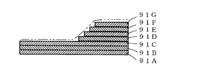
- the number of laminated carbon fiber prepregs 91A to 91G for each portion having different thicknesses It is necessary to make them different from each other and to integrate them by stacking them at accurate positions.
- the carbon fiber prepregs 91A to 91G to be laminated must be prepared in a number of different shapes according to the parts to be laminated, and the types of necessary carbon fiber prepregs are greatly increased.
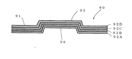
- a plurality of carbon fiber prepregs may be stacked, and unevenness may be formed on the surface of the carbon fiber reinforced plastic by pressurization and thermoforming using a pressure mold in which unevenness is previously provided on the mold surface.
- a plurality of carbon fiber prepregs are formed by pressing the convex portions on one mold surface into the concave portions on the other mold surface. Therefore, as shown in FIG. 11, a carbon fiber reinforced plastic 90 made of a plurality of carbon fiber prepregs 92A, 92B, 92C, and 92D is formed by forming a pair of concave portions 96 on one side and a concave portion 96 on the opposite side. As a result, the shape is limited.
- the present invention has been made in view of the above points, and an object of the present invention is to provide a carbon fiber composite material that can easily form concave and convex portions on the surface and has a high degree of freedom in shape design.
- a plurality of carbon fiber prepregs in which a carbon fiber fabric is impregnated with a thermosetting resin and at least one porous prepreg in which a porous material is impregnated with a thermosetting resin are laminated and integrated by heating and pressing.
- Carbon fiber composite material wherein the porous prepreg is disposed between the carbon fiber prepregs, and the surface of the carbon fiber composite material is constituted by the carbon fiber prepreg, and at least one side of the carbon fiber composite material At least one of a concave portion and a convex portion is formed on the surface of the surface, and the thickness of the porous prepreg is reduced in the concave portion as compared to the general portion without the concave portion and the convex portion, and the porous prepreg is formed in the convex portion.
- the thickness of the carbon fiber composite material is reduced in the concave portion compared to the general portion without the concave portion and the convex portion, and the thickness of the carbon fiber composite material in the convex portion. May be increased.
- the surface on the opposite side of the concave portion and the convex portion may be a flat surface having no concave and convex portions.
- the plurality of carbon fiber prepregs and the porous prepreg may have the same shape in plan view.
- a plurality of the porous prepregs may be overlapped and disposed between the carbon fiber prepregs.
- the carbon fiber prepreg existing between one surface of the carbon fiber composite material and the porous prepreg closest to the surface The number of the carbon fiber prepregs existing between the other surface and the porous prepreg closest to the surface may be equal.
- the carbon fiber prepreg existing between one surface of the carbon fiber composite material and the porous prepreg closest to the surface In the carbon fiber composite material according to any one of (1) to (5), the carbon fiber prepreg existing between one surface of the carbon fiber composite material and the porous prepreg closest to the surface. And the number of carbon fiber prepregs existing between the surface on the other side and the porous prepreg closest to the surface may be different.
- the thickness of the porous prepreg disposed between the plurality of carbon fiber prepregs in the carbon fiber composite material is reduced from the general portion having no irregularities in the concave portion of the carbon fiber composite material, Since the convex portion has a configuration that is larger than that of the general portion, by placing a porous prepreg between a plurality of carbon fiber prepregs and heating and pressing the carbon, at least one of the concave portion and the convex portion is formed on the surface.
- a fiber composite material can be obtained.
- the degree of freedom in shape design Becomes higher.
- the surface on the opposite side of the concave portion and the convex portion is a flat surface having no irregularities, the influence of the shape due to the concave portion and the convex portion on the surface opposite to the concave portion and the convex portion. Can be designed without affecting the plane, and the degree of freedom in shape design is increased. For example, if it is a part, the storage space can be effectively utilized without waste with respect to the space to be stored.
- the carbon fiber composite material of (4) since the plurality of carbon fiber prepregs and the porous prepreg have the same shape in plan view, various types of carbon fiber prepregs having different shapes in order to shape the concave portions and the convex portions, There is no need to laminate a porous prepreg. As a result, it becomes easy to form the unevenness, and the dimensional variation in the product can be suppressed, so that the mass productivity is increased and the work man-hour is reduced.
- the carbon fiber composite material of (6) and (7) when a recessed part and a convex part are formed only in the one side surface of a carbon fiber composite material, or when a recessed part and a convex part are formed in both sides
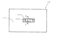
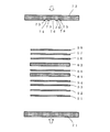
- FIG. 1 is a plan view of a carbon fiber composite material according to a first embodiment of the present invention.
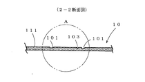
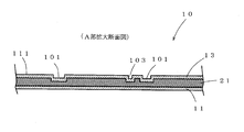
- FIG. 2 is a sectional view taken along line 2-2 of FIG. It is the A section expanded sectional view of FIG. It is a schematic sectional drawing which shows the apparatus at the time of shape
- FIG. 6 is a cross-sectional view along 6-6 in FIG. 5. It is the B section expanded sectional view of FIG. It is a schematic sectional drawing which shows the apparatus at the time of shape
- a carbon fiber composite material 10 according to the first embodiment shown in FIG. 1 is used as an outer plate of a lid in a casing of a notebook computer.
- the outer surface of the carbon fiber composite material 10 is formed with a character composed of a recess 103 in a portion surrounded by a frame-shaped recess 101.
- metal foil may be stuck to the said recessed parts 101 and 103, or coloring resin for decoration may be laminated
- the carbon fiber composite material 10 is composed of a laminate in which one porous prepreg 21 is disposed between two carbon fiber prepregs 11 and 13 and is integrated by heating and pressing.
- the carbon fiber prepregs 11 and 13 are made of a carbon fiber fabric impregnated with a thermosetting resin.
- the carbon fiber woven fabric is excellent in light weight and high rigidity, and is particularly preferably a fabric in which the fibers are not only in one direction, for example, plain weave, twill weave, satin weave and three directions composed of warp and weft. A triaxial weaving made of yarn is suitable.
- the carbon fiber fabric preferably has a fiber weight of 50 to 600 g / m 2 from the viewpoint of impregnation with a thermosetting resin and rigidity.
- thermosetting resin impregnated in the carbon fiber fabric is not particularly limited, but in order to increase the rigidity of the carbon fiber composite material 10, the thermosetting resin itself needs to have a certain degree of rigidity, and an epoxy resin, It can be selected from the group consisting of phenolic resins, mixtures of epoxy resins and phenolic resins.
- the thermosetting resin is preferably flame retardant. Since the phenol resin itself is flame retardant, the additive imparting flame retardancy can be reduced. Therefore, the phenol resin is suitable as a thermosetting resin impregnated in the carbon fiber fabric.
- thermosetting resin is preferably impregnated in the carbon fiber fabric so that the resin weight ratio in the carbon fiber prepreg is 50 to 80%, particularly 55 to 70%. By setting it as the said resin ratio, lightweight property and rigidity can be made more favorable.
- the porous prepreg 21 is obtained by impregnating a porous material with a thermosetting resin.
- the porous material is not particularly limited, and examples thereof include foams and fiber products.
- a foam having an open cell structure is suitable.
- a urethane resin foam, a melamine resin foam, a polyolefin (polyamide) foam, or the like can be selected. Since the foam is open-celled, it can be impregnated with a thermosetting resin and can be molded with a high compression ratio.
- Specific examples of the fiber product include fibrils, yarns, piles, cotton-like materials, woven fabrics, knitted fabrics, nonwoven fabrics, nets, flocked fabrics, and cut products thereof.
- the porous material is preferably a melamine resin foam or a polyamide resin foam.
- the porous material is preferably flame retardant. Since the melamine resin foam has good flame retardancy, it is suitable as the porous material.
- the original thickness of the porous material before compression is appropriately set, and examples thereof include 1 to 25 mm.
- the porous material is made of a foam, the foam preferably has a density before compression of 5 to 80 kg / m 3 from the viewpoints of easy compression, impregnation, light weight, and rigidity.
- thermosetting resin impregnated in the porous material is not particularly limited, but in order to increase the rigidity of the carbon fiber composite material 10, the thermosetting resin itself needs to have a certain degree of rigidity, an epoxy resin, It can be selected from the group consisting of phenolic resins, mixtures of epoxy resins and phenolic resins.
- the thermosetting resin is preferably flame retardant. Since phenol resin has good flame retardancy, it is suitable as a thermosetting resin impregnated in the porous material.
- the thermosetting resin impregnated in the porous prepreg and the thermosetting resin impregnated in the carbon fiber prepreg are the same, and the occurrence of delamination is remarkably reduced by increasing the adhesion. *
- the carbon fiber composite material 10 has the frame-shaped recess 101 and the character recess 103 formed on the outer surface.
- the porous prepreg 21 is greatly compressed and the thickness of the porous prepreg 21 is reduced compared to the general portion 111 having no concave and convex portions, thereby reducing the thickness of the carbon fiber composite material 10.
- the thickness is decreasing.
- the surface on the opposite side in the position of the said recessed parts 101 and 103 is comprised by the plane without an unevenness
- the carbon fiber prepregs 11 and 13 and the porous prepreg 21 have the same shape in plan view.
- the number of laminated carbon fiber prepregs and porous prepregs is appropriately set according to the use and required strength of the carbon fiber composite material.
- the pattern part which consists of the frame shape of FIG. 1 and the recessed part of a character is the size of 30 mm x 100 mm in length and width, and the depth of a recessed part is 0.5 mm.
- the carbon fiber prepreg 11 and the porous prepreg 21 before curing are interposed between the lower pressurization die 31 and the upper pressurization die 32 in which the recess forming protrusions 33 and 34 are formed on the mold surface.
- the carbon fiber prepregs 13 are laminated in this order.
- the carbon fiber prepreg 11, the porous prepreg 21, and the carbon fiber prepreg 13 are pressurized and heated in a laminated state by bringing the lower pressure mold 31 and the upper pressure mold 32 close to each other.
- the lower pressurization mold 31 and the upper pressurization mold 32 are heated to a temperature at which the thermosetting resin can be cured by heating means such as an electric heater. *
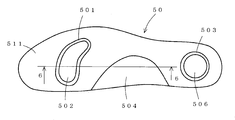
- the carbon fiber composite material 50 of the second embodiment shown in FIG. 5 is used as an insole for an artificial leg.
- concave portions 501 and 503 and convex portions 502, 504, and 506 are formed near the base of the toes, the arch portion, and the heel portion.
- the carbon fiber composite material 50 includes carbon fiber prepregs 51, 52, 53, and 54, a porous prepreg 61, a carbon fiber prepreg 55, a porous prepreg 62, and carbon fiber prepregs 56, 57, and 58 in order from the bottom layer on the back side. It is composed of a 10-layer laminate that is laminated and integrated by heating and pressing.
- the carbon fiber prepregs 51 to 58 and the porous prepregs 61 and 62 in the second embodiment have the same configuration as the carbon fiber prepregs 11 and 13 and the porous prepreg 21 in the first embodiment. *
- the porous prepregs 61 and 62 are greatly compressed and the thickness of the porous prepreg is reduced compared to the general part 511 having no recesses and protrusions, thereby reducing the carbon fiber composite material 50.
- the thickness has decreased.
- the compression amount of the porous prepregs 61 and 62 is small and the thickness of the porous prepreg is increased compared to the general portion 511 having no concave portions and convex portions, thereby increasing the thickness of the porous prepreg.
- the thickness of the carbon fiber composite material 50 is increasing.
- the opposite surfaces at the positions of the concave portions 501 and 503 and the convex portions 502, 504, and 506 are configured as flat surfaces having no irregularities. *
- the plurality of carbon fiber prepregs 51 to 58 and the porous prepregs 61 and 62 have the same shape in plan view.
- the number of laminated carbon fiber prepregs and porous prepregs is appropriately set according to the use of the carbon fiber composite material and the required strength.
- the lower pressurizing die 71 and the upper pressurizing die 72 are brought close to pressurize and heat the carbon fiber prepreg and the porous prepreg in the laminated state.
- the lower pressurizing mold 71 and the upper pressurizing mold 72 are heated to a temperature at which the thermosetting resin can be cured by heating means such as an electric heater.
- the recesses 501 are formed in the portions pressed by the recess formation protrusions 73 and 75 of the upper pressurization mold 72. 503 is formed.
- the convex portions 502, 504, and 506 are formed at portions that contact the depressions 74, 76, and 78.
- the carbon fiber prepregs 51 to 56 and the porous prepregs 61 and 62 are cured, so that the carbon fiber prepregs 51 to 58 and the porous prepregs 61 and 62 are integrated.
- the shape is fixed, and the carbon fiber composite material 50 is obtained. *
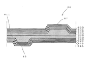
- FIG. 9 shows an enlarged view of a part of the carbon fiber composite material 80 of the third embodiment having another laminated structure.
- the carbon fiber composite material 80 two porous prepregs 81A and 81B are stacked, and four carbon fiber prepregs 82A, 82B, 82C, 82D, 83A, 83B, 83C, and 83D are laminated on both sides thereof.
- the laminate is composed of 10 layers integrated by heating and pressing. Convex portions 85 and 87 are formed on both side surfaces of the carbon fiber composite material 80.
- the carbon fiber prepregs 82A to 82D and 83A to 83D and the porous prepregs 81A and 81B in the third embodiment have the same configuration as the carbon fiber prepregs 11 and 13 and the porous prepreg 21 of the first embodiment.
- the four carbon fiber prepregs 82A to 82D exist between the surface on one side where the convex portion 85 is formed and the porous prepreg 81A closest to the surface.
- the compression amount of the porous prepregs 81A and 81B is small and the thickness of the porous prepregs 81A and 81B is increased as compared with the general portion 811 having no concave portions and convex portions, whereby the carbon The thickness of the fiber composite 80 is increasing.
- the surface on the opposite side in the position of the said convex parts 85 and 87 is comprised by the plane without an unevenness
- the plurality of carbon fiber prepregs 82A to 82D, 83A to 83D and the porous prepregs 81A and 81B all have the same shape in plan view.
- the number of laminated carbon fiber prepregs and porous prepregs is appropriately set according to the use of the carbon fiber composite material and the required strength.
- Example 1 The example which shape
- phenol resin Asahi Organic Materials Co., Ltd., product name: PAPS-4 and Asahi Organic Materials Co., Ltd., product name: hexamethylenetetramine mixed at 100: 12
- a plain weave carbon fiber fabric (manufactured by Toho Tex Co., Ltd., product name: W-3101, fiber weight 200 g / m 2 ) is dipped in this phenolic resin solution, taken out, and then naturally dried at room temperature of 25 ° C. for 2 hours. Furthermore, it dried for 1 hour in 60 degreeC atmosphere, and formed two carbon fiber prepregs.
- the carbon fiber fabric used was cut into a plane size of 200 ⁇ 300 mm (weight 12 g / sheet).
- a foam having an open cell structure a melamine resin foam (made by BASF, product name: Vasotect V3012, density 9 kg / m 3 ) cut to a thickness of 10 mm and a planar size of 200 ⁇ 300 mm (weight: 5.4 g), carbon
- a phenol resin solution taken out, dried naturally at room temperature of 25 ° C. for 2 hours, and further dried in an atmosphere of 60 ° C. for 1 hour to form one porous prepreg.
- the carbon fiber prepreg and the porous prepreg are laminated and heated on the upper and lower molds having cavities to obtain a carbon fiber composite. That is, the stacking sequence shown in FIG. 4, that is, a carbon fiber prepreg, a porous prepreg, and a carbon fiber prepreg are stacked and disposed on the cavity of the lower metal mold made of SUS having a release agent applied to the surface in advance. .
- the laminate on the lower mold is pressed by applying an area pressure of 5 MPa at 180 ° C. for 3 minutes with an upper mold having protrusions for forming recesses on the mold surface. Then, the phenol resin was reaction-cured in the compressed state.
- the heating at that time was performed by a casting heater attached to the upper and lower molds.
- the thickness after compression designed the cavity according to the general part which forms a flat plate according to a product shape.
- the upper and lower molds were cooled at room temperature and then opened to obtain the carbon fiber composite material 10 of FIG. 1 in which the carbon fiber prepreg and the porous prepreg were laminated and integrated.
- Example 2 The example which shape
- the heating at that time was performed by a casting heater attached to the upper and lower molds.
- the thickness after compression designed the cavity according to the general part which forms a flat plate according to a product shape.
- the upper and lower molds were cooled at room temperature and then opened to obtain a carbon fiber composite material in which the carbon fiber prepreg and the porous prepreg were laminated and integrated.
- trimming was performed to cut an excess portion around the carbon fiber composite material, and the carbon fiber composite material 50 shown in FIG. 5 was obtained.
- the present invention includes:
- the plurality of carbon fiber prepregs and the porous prepreg are not limited to the same shape in plan view, depending on the shape of the product to be molded, depending on the stacking position, the planar shape of the two types of prepregs, Can be cut and designed.
- the plan view shape of the porous prepreg can be cut and designed according to the lamination position.
- a carbon fiber composite material in which at least one of a concave portion and a convex portion is formed on the surface can be obtained by arranging a porous prepreg between a plurality of carbon fiber prepregs and heating and pressing. .
- a porous prepreg between a plurality of carbon fiber prepregs and heating and pressing.
Landscapes
- Engineering & Computer Science (AREA)
- Mechanical Engineering (AREA)
- Chemical & Material Sciences (AREA)
- Composite Materials (AREA)
- Laminated Bodies (AREA)
- Moulding By Coating Moulds (AREA)
- Casting Or Compression Moulding Of Plastics Or The Like (AREA)
- Reinforced Plastic Materials (AREA)
Abstract
Description
(1)炭素繊維織物に熱硬化性樹脂が含浸した複数枚の炭素繊維プリプレグと、多孔質材に熱硬化性樹脂が含浸した少なくとも1枚の多孔質プレプレグが積層されて加熱と加圧により一体化された炭素繊維複合材であって、前記多孔質プリプレグが前記炭素繊維プリプレグ間に配置されて前記炭素繊維複合材の表面が前記炭素繊維プリプレグで構成され、前記炭素繊維複合材の少なくとも一側の表面には凹部と凸部の少なくとも一方が賦形され、前記凹部及び凸部の無い一般部と比べて前記凹部では前記多孔質プリプレグの厚みが減少し、前記凸部では前記多孔質プリプレグの厚みが増大していることを特徴とする炭素繊維複合材。
図1の炭素繊維複合材10を成形する例を示す。熱硬化性樹脂としてフェノール樹脂(旭有機材料株式会社製、品名;PAPS-4と旭有機材料株式会社製、品名;ヘキサメチレンテトラミンを100:12で混合したもの)をメタノールに30wt%の濃度となるように溶解した。このフェノール樹脂溶液中に平織の炭素繊維織物(東邦テックス株式会社製、品名;W-3101、繊維重さ200g/m2)を漬け、取り出した後に25℃の室温にて2時間自然乾燥し、更に60℃の雰囲気下にて1時間乾燥させて炭素繊維プリプレグを2枚形成した。炭素繊維織物は、200×300mmの平面サイズに裁断したもの(重量12g/枚)を使用した。
図5の炭素繊維複合材50を成形する例を示す。実施例1と同様にして炭素繊維プリプレグを8枚形成し、また多孔質プリプレグを2枚形成した。次に、予め離型剤を表面に塗布したSUS製の下側金型上に、図8に示した積層順序で、炭素繊維プリプレグと多孔質プリプレグを順に積層して配置する。次に、下側金型上の積層体を、型面に凹部形成用の突起と凸部形成用の窪みが形成された上側金型により、180℃で3分間、5MPaの面圧をかけて押圧し、圧縮及び加熱を行ない、前記圧縮状態でフェノール樹脂を反応硬化させた。その際の加熱は、上下金型に取り付けられた鋳込みヒーターにより行なった。圧縮後の厚みは、製品形状に応じて平板を形成する一般部に応じてキャビティを設計した。その後、上下金型を室温で冷却させた後に開き、前記炭素繊維プリプレグと多孔質プリプレグが積層一体化した炭素繊維複合材を得た。その後、炭素繊維複合材の周囲の余剰部分をカットするトリミングを行い、図5の炭素繊維複合材50を得た。
前記複数の炭素繊維プリプレグと前記多孔質プリプレグは、平面視形状が同一である場合に限られず、成形する製品の形状に応じて、積層位置に応じて、上記2種類のプリプレグの平面形状を、裁断、設計することができる。特に多孔質プリプレグの平面視形状を、その積層位置に応じて、裁断、設計することができる。
11、13、51~58、82A~82D、83A~83D 炭素繊維プリプレグ
21、61、62、81A、81B 多孔質プリプレグ 101、103、501、503 凹部
502、504、506、85、87 凸部
111、511、811 一般部
Claims (7)
- 炭素繊維織物に熱硬化性樹脂が含浸した複数枚の炭素繊維プリプレグと、多孔質材に熱硬化性樹脂が含浸した少なくとも一枚の多孔質プレプレグが積層されて加熱と加圧により一体化された炭素繊維複合材であって、
前記多孔質プリプレグが前記炭素繊維プリプレグ間に配置されて前記炭素繊維複合材の表面が前記炭素繊維プリプレグで構成され、
前記炭素繊維複合材の少なくとも一側の表面には凹部と凸部の少なくとも一方が賦形され、
前記凹部及び凸部の無い一般部と比べて前記凹部では前記多孔質プリプレグの厚みが減少し、前記凸部では前記多孔質プリプレグの厚みが増大していることを特徴とする炭素繊維複合材。 - 前記凹部及び凸部の無い一般部と比べて前記凹部では前記炭素繊維複合材の厚みが減少し、前記凸部では前記炭素繊維複合材の厚みが増大していることを特徴とする請求項1に記載の炭素繊維複合材。
- 前記凹部及び凸部の反対側の表面は凹凸の無い平面からなることを特徴とする請求項1又は2に記載の炭素繊維複合材。
- 前記複数の炭素繊維プリプレグと前記多孔質プリプレグは平面視同一形状からなることを特徴とする請求項1から3の何れか一項に記載の炭素繊維複合材。
- 前記多孔質プリプレグは、複数枚重なって前記炭素繊維プリプレグ間に配置されていることを特徴とする請求項1から4の何れか一項に記載の炭素繊維複合材。
- 前記炭素繊維複合材の一側の表面と該表面に最も近い前記多孔質プリプレグまでの間に存在する前記炭素繊維プリプレグの枚数と、他側の表面と該表面に最も近い前記多孔質プリプレグまでの間に存在する前記炭素繊維プリプレグの枚数が等しいことを特徴とする請求項1から5の何れか一項に記載の炭素繊維複合材。
- 前記炭素繊維複合材の一側の表面と該表面に最も近い前記多孔質プリプレグまでの間に存在する前記炭素繊維プリプレグの枚数と、他側の表面と該表面に最も近い前記多孔質プリプレグまでの間に存在する前記炭素繊維プリプレグの枚数が異なることを特徴とする請求項1から5の何れか一項に記載の炭素繊維複合材。
Priority Applications (3)
| Application Number | Priority Date | Filing Date | Title |
|---|---|---|---|
| EP15796498.2A EP3147108B1 (en) | 2014-05-21 | 2015-04-20 | Carbon fiber composite material |
| CN201580001074.XA CN105324233B (zh) | 2014-05-21 | 2015-04-20 | 碳纤维复合材料 |
| US14/899,904 US10086581B2 (en) | 2014-05-21 | 2015-04-20 | Carbon fiber composite material |
Applications Claiming Priority (2)
| Application Number | Priority Date | Filing Date | Title |
|---|---|---|---|
| JP2014-105477 | 2014-05-21 | ||
| JP2014105477A JP6479340B2 (ja) | 2014-05-21 | 2014-05-21 | 炭素繊維複合材 |
Publications (1)
| Publication Number | Publication Date |
|---|---|
| WO2015178141A1 true WO2015178141A1 (ja) | 2015-11-26 |
Family
ID=54553817
Family Applications (1)
| Application Number | Title | Priority Date | Filing Date |
|---|---|---|---|
| PCT/JP2015/061970 Ceased WO2015178141A1 (ja) | 2014-05-21 | 2015-04-20 | 炭素繊維複合材 |
Country Status (6)
| Country | Link |
|---|---|
| US (1) | US10086581B2 (ja) |
| EP (1) | EP3147108B1 (ja) |
| JP (1) | JP6479340B2 (ja) |
| CN (1) | CN105324233B (ja) |
| TW (1) | TWI648161B (ja) |
| WO (1) | WO2015178141A1 (ja) |
Cited By (5)
| Publication number | Priority date | Publication date | Assignee | Title |
|---|---|---|---|---|
| JP2017030165A (ja) * | 2015-07-29 | 2017-02-09 | 株式会社イノアックコーポレーション | 炭素繊維複合材およびその製造方法 |
| JP2018069557A (ja) * | 2016-10-28 | 2018-05-10 | 株式会社イノアックコーポレーション | 刻印を有する成形体と刻印を有する成形体の製造方法 |
| JP2020023647A (ja) * | 2018-08-08 | 2020-02-13 | 株式会社イノアックコーポレーション | 繊維強化樹脂成形体 |
| US20220274349A1 (en) * | 2020-10-09 | 2022-09-01 | Peter Thomas Evers, JR. | Multilayer assemblies with surface depressions and methods of producing and using them |
| CN118789852A (zh) * | 2024-09-12 | 2024-10-18 | 浙江联洋新材料股份有限公司 | 一种碳纤维增强复合材料的制备方法 |
Families Citing this family (9)
| Publication number | Priority date | Publication date | Assignee | Title |
|---|---|---|---|---|
| JP6754273B2 (ja) * | 2016-11-08 | 2020-09-09 | 東京製綱株式会社 | 連続繊維補強材 |
| CN109483904A (zh) * | 2017-09-11 | 2019-03-19 | 莹信工业股份有限公司 | 复合材轮圈的制法与复合材轮圈 |
| CN108928016A (zh) * | 2017-09-22 | 2018-12-04 | 中国航空工业集团公司基础技术研究院 | 一种具有高精度表面微结构的复合材料及制备方法 |
| JP6971840B2 (ja) * | 2017-12-27 | 2021-11-24 | 株式会社イノアックコーポレーション | 回転翼及びそれを用いた無人航空機 |
| JP7493439B2 (ja) * | 2020-12-14 | 2024-05-31 | 株式会社イノアックコーポレーション | 繊維強化成形体の製造方法と繊維強化成形体 |
| JP7419291B2 (ja) * | 2021-04-28 | 2024-01-22 | 株式会社イノアックコーポレーション | 繊維強化成形体の製造方法、樹脂シート、及び樹脂シートの製造方法 |
| CN115835945A (zh) * | 2020-07-06 | 2023-03-21 | 井上株式会社 | 纤维增强树脂成型体及其制造方法、纤维增强树脂成型用预浸料、纤维增强成型体、纤维增强成型体的制造方法、树脂片、纤维增强三明治型复合体以及纤维增强成型体的制造方法 |
| JP7832446B2 (ja) * | 2021-11-19 | 2026-03-18 | 日亜化学工業株式会社 | 発光素子用基板、発光素子用基板を用いた発光装置及び発光素子用基板の製造方法 |
| JP2023150135A (ja) * | 2022-03-31 | 2023-10-16 | 株式会社イノアックコーポレーション | 繊維強化成形体、立体物成形用プリプレグ、及び繊維強化成形体の製造方法 |
Citations (7)
| Publication number | Priority date | Publication date | Assignee | Title |
|---|---|---|---|---|
| JPH0929920A (ja) * | 1995-07-20 | 1997-02-04 | Dainippon Printing Co Ltd | 熱硬化性樹脂化粧板の製造方法 |
| JPH09254265A (ja) * | 1996-03-26 | 1997-09-30 | Nikon Corp | 炭素繊維強化型樹脂板及びその製造方法 |
| JP2003160382A (ja) * | 2001-11-26 | 2003-06-03 | Mitsubishi Electric Corp | 高熱伝導性炭素繊維強化複合材料およびその製造方法 |
| JP2008207523A (ja) * | 2007-02-28 | 2008-09-11 | Toray Ind Inc | X線カセッテ用パネル |
| JP2010120167A (ja) * | 2008-11-17 | 2010-06-03 | Toray Ind Inc | プリフォームおよび繊維強化プラスチックの製造方法 |
| JP2011021303A (ja) * | 2009-07-17 | 2011-02-03 | Mitsubishi Plastics Inc | 炭素繊維不織布、炭素繊維強化樹脂シートおよび炭素繊維強化樹脂成形体 |
| JP2012025149A (ja) * | 2010-03-26 | 2012-02-09 | Dainippon Printing Co Ltd | 自動車部材用の繊維強化複合材、及びその製造方法 |
Family Cites Families (14)
| Publication number | Priority date | Publication date | Assignee | Title |
|---|---|---|---|---|
| US4250136A (en) | 1979-10-22 | 1981-02-10 | Composite Technology Corporation | Method of forming a composite structure |
| US4695501A (en) * | 1984-04-10 | 1987-09-22 | Fibre Converters, Inc. | Thermoformable composite articles |
| JP2992620B2 (ja) * | 1990-09-07 | 1999-12-20 | 株式会社シマノ | 自転車用靴の靴底及びその製造方法 |
| JP3279048B2 (ja) | 1994-03-07 | 2002-04-30 | 東レ株式会社 | 補強織物とそれを用いたfrp |
| TW354280B (en) * | 1994-08-04 | 1999-03-11 | Teijin Ltd | Material of a composite molded article of a fiber-reinforced resin of foamed core sandwichded layer and preparation thereof |
| JPH08276525A (ja) * | 1995-01-26 | 1996-10-22 | Sumitomo Electric Ind Ltd | 積層複合材料及びその製造方法 |
| US6451231B1 (en) | 1997-08-21 | 2002-09-17 | Henkel Corporation | Method of forming a high performance structural foam for stiffening parts |
| US6261675B1 (en) * | 1999-03-23 | 2001-07-17 | Hexcel Corporation | Core-crush resistant fabric and prepreg for fiber reinforced composite sandwich structures |
| JP2004209717A (ja) | 2002-12-27 | 2004-07-29 | Toray Ind Inc | 繊維強化成形品 |
| DE102004004548B4 (de) * | 2004-01-29 | 2007-01-04 | Ansgar Scherf | Verkleidungselement und Verfahren zu dessen Herstellung |
| JP4558091B1 (ja) | 2009-10-29 | 2010-10-06 | 株式会社イノアックコーポレーション | 繊維強化成形体及びその製造方法 |
| WO2011149706A1 (en) * | 2010-05-27 | 2011-12-01 | Dow Global Technologies Llc | Method of manufacturing a shaped foam article |
| CN102309820A (zh) * | 2010-06-29 | 2012-01-11 | 上海世鹏实验室科技发展有限公司 | 一种复合结构型材及立体定位床 |
| JP5606881B2 (ja) | 2010-11-19 | 2014-10-15 | 津田駒工業株式会社 | 炭素繊維基材及び炭素繊維強化プラスチック |
-
2014
- 2014-05-21 JP JP2014105477A patent/JP6479340B2/ja active Active
-
2015
- 2015-04-20 US US14/899,904 patent/US10086581B2/en active Active
- 2015-04-20 CN CN201580001074.XA patent/CN105324233B/zh active Active
- 2015-04-20 WO PCT/JP2015/061970 patent/WO2015178141A1/ja not_active Ceased
- 2015-04-20 EP EP15796498.2A patent/EP3147108B1/en active Active
- 2015-05-20 TW TW104116080A patent/TWI648161B/zh active
Patent Citations (7)
| Publication number | Priority date | Publication date | Assignee | Title |
|---|---|---|---|---|
| JPH0929920A (ja) * | 1995-07-20 | 1997-02-04 | Dainippon Printing Co Ltd | 熱硬化性樹脂化粧板の製造方法 |
| JPH09254265A (ja) * | 1996-03-26 | 1997-09-30 | Nikon Corp | 炭素繊維強化型樹脂板及びその製造方法 |
| JP2003160382A (ja) * | 2001-11-26 | 2003-06-03 | Mitsubishi Electric Corp | 高熱伝導性炭素繊維強化複合材料およびその製造方法 |
| JP2008207523A (ja) * | 2007-02-28 | 2008-09-11 | Toray Ind Inc | X線カセッテ用パネル |
| JP2010120167A (ja) * | 2008-11-17 | 2010-06-03 | Toray Ind Inc | プリフォームおよび繊維強化プラスチックの製造方法 |
| JP2011021303A (ja) * | 2009-07-17 | 2011-02-03 | Mitsubishi Plastics Inc | 炭素繊維不織布、炭素繊維強化樹脂シートおよび炭素繊維強化樹脂成形体 |
| JP2012025149A (ja) * | 2010-03-26 | 2012-02-09 | Dainippon Printing Co Ltd | 自動車部材用の繊維強化複合材、及びその製造方法 |
Cited By (9)
| Publication number | Priority date | Publication date | Assignee | Title |
|---|---|---|---|---|
| JP2017030165A (ja) * | 2015-07-29 | 2017-02-09 | 株式会社イノアックコーポレーション | 炭素繊維複合材およびその製造方法 |
| JP2018069557A (ja) * | 2016-10-28 | 2018-05-10 | 株式会社イノアックコーポレーション | 刻印を有する成形体と刻印を有する成形体の製造方法 |
| JP2020023647A (ja) * | 2018-08-08 | 2020-02-13 | 株式会社イノアックコーポレーション | 繊維強化樹脂成形体 |
| WO2020031919A1 (ja) * | 2018-08-08 | 2020-02-13 | 株式会社イノアックコーポレーション | 繊維強化樹脂成形体およびその製造方法 |
| JP7146519B2 (ja) | 2018-08-08 | 2022-10-04 | 株式会社イノアックコーポレーション | 繊維強化樹脂成形体及び繊維強化樹脂成形体の製造方法 |
| US20220274349A1 (en) * | 2020-10-09 | 2022-09-01 | Peter Thomas Evers, JR. | Multilayer assemblies with surface depressions and methods of producing and using them |
| US11858221B2 (en) * | 2020-10-09 | 2024-01-02 | Hanwha Azdel, Inc. | Multilayer assemblies with surface depressions and methods of producing and using them |
| CN118789852A (zh) * | 2024-09-12 | 2024-10-18 | 浙江联洋新材料股份有限公司 | 一种碳纤维增强复合材料的制备方法 |
| CN118789852B (zh) * | 2024-09-12 | 2024-12-10 | 浙江联洋新材料股份有限公司 | 一种碳纤维增强复合材料的制备方法 |
Also Published As
| Publication number | Publication date |
|---|---|
| TWI648161B (zh) | 2019-01-21 |
| CN105324233B (zh) | 2019-11-15 |
| CN105324233A (zh) | 2016-02-10 |
| JP2015217662A (ja) | 2015-12-07 |
| TW201609406A (zh) | 2016-03-16 |
| JP6479340B2 (ja) | 2019-03-06 |
| US20160136922A1 (en) | 2016-05-19 |
| EP3147108B1 (en) | 2020-05-06 |
| EP3147108A1 (en) | 2017-03-29 |
| EP3147108A4 (en) | 2018-01-24 |
| US10086581B2 (en) | 2018-10-02 |
Similar Documents
| Publication | Publication Date | Title |
|---|---|---|
| JP6479340B2 (ja) | 炭素繊維複合材 | |
| JP6685616B2 (ja) | 炭素繊維複合材とその製造方法 | |
| JP4558091B1 (ja) | 繊維強化成形体及びその製造方法 | |
| KR101926945B1 (ko) | 섬유 강화 복합 재료 성형품 및 그 제조 방법 | |
| JP6415885B2 (ja) | 孔あき炭素繊維複合材の製造方法 | |
| JP5761867B2 (ja) | 繊維強化された樹脂基材又は樹脂成形体の製造方法及びこの製造方法に使用する可塑化吐出機 | |
| JP7442123B2 (ja) | 繊維強化複合材料サンドイッチコア及び繊維強化複合材料サンドイッチコアの製造方法 | |
| EP3991964A1 (en) | Honeycomb layered body and production method therefor | |
| CN106739245A (zh) | 电子产品外壳及其制造方法 | |
| JP6665149B2 (ja) | 繊維強化樹脂体及びその製造方法 | |
| JP2016002723A (ja) | 炭素繊維複合材とその製造方法 | |
| JP6847510B2 (ja) | 炭素繊維複合化粧板 | |
| JP6652523B2 (ja) | 強化繊維基材及びプリフォーム。 | |
| KR101447136B1 (ko) | 섬유 강화 복합재의 성형방법 | |
| ITUA20164146A1 (it) | Procedimento di fabbricazione di sci, ed attrezzi di vario genere per scivolare sulla neve, con materiali termoformabili aventi strutture portanti a base di fibre di carbonio, e stampi di termoformatura di tali prodotti, nonche’ sci, ed attrezzi di scivolamento sulla neve cosi’ ottenuti | |
| JP2023150135A (ja) | 繊維強化成形体、立体物成形用プリプレグ、及び繊維強化成形体の製造方法 | |
| US20140184044A1 (en) | Chassis for a computing device | |
| JP2019042975A (ja) | 繊維強化成形体及びその製造方法 | |
| JP7356840B2 (ja) | 表面に凹凸が賦形されたハニカム積層体とその製造方法 | |
| JP2006015611A (ja) | サンドイッチ積層板の製造方法 | |
| KR101558265B1 (ko) | 인서트폼을 이용한 차량용 휠 제조방법 및 이에 의해 제조된 차량용 휠 | |
| JP7146519B2 (ja) | 繊維強化樹脂成形体及び繊維強化樹脂成形体の製造方法 | |
| JP7220004B2 (ja) | 繊維強化樹脂複合成形体とその製造方法 | |
| JP7139296B2 (ja) | 繊維強化樹脂複合成形体とその製造方法 | |
| CN109849259A (zh) | 一种制造壳体的方法 |
Legal Events
| Date | Code | Title | Description |
|---|---|---|---|
| WWE | Wipo information: entry into national phase |
Ref document number: 201580001074.X Country of ref document: CN |
|
| REEP | Request for entry into the european phase |
Ref document number: 2015796498 Country of ref document: EP |
|
| WWE | Wipo information: entry into national phase |
Ref document number: 14899904 Country of ref document: US Ref document number: 2015796498 Country of ref document: EP |
|
| 121 | Ep: the epo has been informed by wipo that ep was designated in this application |
Ref document number: 15796498 Country of ref document: EP Kind code of ref document: A1 |
|
| NENP | Non-entry into the national phase |
Ref country code: DE |