WO2015178203A1 - コネクタ - Google Patents
コネクタ Download PDFInfo
- Publication number
- WO2015178203A1 WO2015178203A1 PCT/JP2015/063164 JP2015063164W WO2015178203A1 WO 2015178203 A1 WO2015178203 A1 WO 2015178203A1 JP 2015063164 W JP2015063164 W JP 2015063164W WO 2015178203 A1 WO2015178203 A1 WO 2015178203A1
- Authority
- WO
- WIPO (PCT)
- Prior art keywords
- connector housing
- panel
- grommet
- connector
- detection piece
- Prior art date
- Legal status (The legal status is an assumption and is not a legal conclusion. Google has not performed a legal analysis and makes no representation as to the accuracy of the status listed.)
- Ceased
Links
Images


Classifications
-
- H—ELECTRICITY
- H01—ELECTRIC ELEMENTS
- H01R—ELECTRICALLY-CONDUCTIVE CONNECTIONS; STRUCTURAL ASSOCIATIONS OF A PLURALITY OF MUTUALLY-INSULATED ELECTRICAL CONNECTING ELEMENTS; COUPLING DEVICES; CURRENT COLLECTORS
- H01R13/00—Details of coupling devices of the kinds covered by groups H01R12/70 or H01R24/00 - H01R33/00
- H01R13/46—Bases; Cases
- H01R13/52—Dustproof, splashproof, drip-proof, waterproof, or flameproof cases
- H01R13/5202—Sealing means between parts of housing or between housing part and a wall, e.g. sealing rings
-
- H—ELECTRICITY
- H01—ELECTRIC ELEMENTS
- H01R—ELECTRICALLY-CONDUCTIVE CONNECTIONS; STRUCTURAL ASSOCIATIONS OF A PLURALITY OF MUTUALLY-INSULATED ELECTRICAL CONNECTING ELEMENTS; COUPLING DEVICES; CURRENT COLLECTORS
- H01R13/00—Details of coupling devices of the kinds covered by groups H01R12/70 or H01R24/00 - H01R33/00
- H01R13/64—Means for preventing incorrect coupling
- H01R13/641—Means for preventing incorrect coupling by indicating incorrect coupling; by indicating correct or full engagement
-
- H—ELECTRICITY
- H01—ELECTRIC ELEMENTS
- H01R—ELECTRICALLY-CONDUCTIVE CONNECTIONS; STRUCTURAL ASSOCIATIONS OF A PLURALITY OF MUTUALLY-INSULATED ELECTRICAL CONNECTING ELEMENTS; COUPLING DEVICES; CURRENT COLLECTORS
- H01R13/00—Details of coupling devices of the kinds covered by groups H01R12/70 or H01R24/00 - H01R33/00
- H01R13/73—Means for mounting coupling parts to apparatus or structures, e.g. to a wall
- H01R13/74—Means for mounting coupling parts in openings of a panel
- H01R13/741—Means for mounting coupling parts in openings of a panel using snap fastening means
- H01R13/743—Means for mounting coupling parts in openings of a panel using snap fastening means integral with the housing
Definitions
- the present invention relates to a connector.
- Patent Document 1 discloses a connector attached to a vehicle panel.
- the connector includes a male housing that is inserted into the mounting opening of the panel and attached to the panel.
- An elastic male grommet is attached to the male housing so as to cover the outer periphery thereof. When the male housing is correctly inserted into the mounting opening of the panel, the grommet is brought into close contact with the wall surface of the panel, thereby ensuring the waterproofness of the male housing.
- the present invention has been completed based on the above circumstances, and a connector that can confirm whether or not the connector housing is correctly attached to the panel even when the connector housing is covered with a grommet.
- the purpose is to provide.
- the present invention provides a connector housing that is inserted into a mounting hole of a panel, and is attached to the connector housing so as to cover an outer periphery of the connector housing, and when the connector housing is inserted into the mounting hole of the panel, A connector having an elastic grommet that is in close contact with the wall surface, and the outer periphery of the connector housing interferes with the panel when the connector housing is in an incompletely inserted state in the mounting hole of the panel.
- the grommet protrudes outwardly and presses the grommet at the protruding portion to bulge the grommet outward.
- the grommet is elastically restored to expand the grommet. Detection piece that releases the pressing state on the grommet so that the protruding state disappears Characterized in place are provided.
- the grommet When the connector housing is incompletely inserted into the panel, the grommet is bulged outward by the protruding portion of the detection piece. On the other hand, when the connector housing is correctly inserted into the panel, the pressing state of the detection piece against the grommet is released, and the expanded state of the grommet substantially disappears. For this reason, it is possible to know that the connector housing is not correctly inserted into the panel, that is, the connector is not correctly attached to the panel, by visually confirming or tapping that the grommet is expanded.
- the detection piece When the connector housing is correctly inserted into the mounting hole of the panel, the detection piece is disposed so as to be able to be locked with the panel in a direction opposite to the insertion direction of the connector housing, whereby the connector housing is It has a lock protrusion that restricts the panel from coming out in the direction opposite to the insertion direction. According to this, since the detection piece serves as both the attachment detection means and the lock means for the panel, the entire configuration can be simplified as compared with the case where the attachment detection means and the lock means are provided separately. .
- the detection piece is configured to extend substantially along the insertion direction of the connector housing, and includes a fulcrum portion connected to the outer surface of the connector housing in the extension direction.
- the front end portion in the insertion direction interferes with the panel and tilts in a seesaw shape around the fulcrum portion, so that the rear end portion in the insertion direction protrudes to the outside.
- the grommet is pressed. According to this, attachment detection to a panel can be easily performed with the detection piece of a comparatively simple structure.
- the protrusion located on the rear end side in the insertion direction with the fulcrum portion interposed therebetween is more in the insertion direction than the interference portion located on the front end portion side in the insertion direction with the fulcrum portion interposed therebetween. It has a long shape. According to this, when the detection piece tilts in a seesaw shape around the fulcrum portion, the protruding amount of the protruding portion increases, and as a result, the protruding amount of the grommet pushed up to the protruding portion also increases. The visibility or tactile property of the part is improved, and the detection reliability is improved.
- the region of the grommet that is pressed by the protruding portion of the detection piece is a thin portion that is thinner than the surroundings. According to this, even if the pressing force when the protruding portion of the detection piece presses the thin part of the grommet is small, the grommet can be bulged stably and reliably. And since interference resistance resulting from interference with a detection piece and a panel can be made small, the workability
- the connector housing has a substantially square cross section, and the detection pieces are provided on each of the four sides constituting the outer periphery of the connector housing. According to this, the incomplete insertion state of the connector housing can be reliably detected by the detection piece provided on at least one of the four sides of the connector housing.
- the connector according to the present embodiment includes a connector housing 10 and a grommet 60 attached to the connector housing 10 so as to cover the outer periphery of the connector housing 10.
- the connector housing 10 is inserted into an attachment hole 51 provided in the panel 50 in a state of being fitted to the mating connector housing 90, and is attached to the panel 50 via a lock projection 33 described later.
- the side on which the mating connector housing 90 is located at the start of fitting of the two connector housings 10 and 90 is the front.
- the vertical direction is based on each figure.
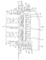
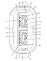
- the connector housing 10 is made of a synthetic resin, and as shown in FIG. 4, the connector housing 10 has a substantially rectangular cross section as a whole and is vertically long. As shown in FIG. 1, a block-shaped housing body 11 and a housing body 11 And a cylindrical hood portion 12 protruding forward from the outer peripheral edge of the front end. A partition part 13 is installed substantially horizontally at the center of the hood part 12 in the height direction, and the inside of the hood part 12 is divided into a pair of upper and lower fitting parts 14 via the partition part 13.
- the housing body 11 is provided with a plurality of cavities 15 at positions corresponding to the respective fitting portions 14, and retainer mounting holes 16 communicating with the cavities 15. .
- a terminal fitting 20 is inserted into each cavity 15 from behind.
- the terminal fitting 20 has a barrel portion 22 connected to the electric wire 21 and the rubber plug 40 by pressure bonding, and a tab portion 23 protruding forward.
- the terminal fittings 20 can be elastically locked to the lances 17 projecting from the cavities 15, so that the terminal fittings 20 are prevented from falling into the cavities 15. .
- the tab portion 23 protrudes from the hood portion 12. Further, the terminal fittings 20 that are normally inserted into the cavities 15 are secondarily prevented from coming off by a retainer (not shown) inserted into the retainer mounting hole 16.
- the mating connector housing 90 is made of synthetic resin, and has a substantially square block shape that can be fitted to each fitting portion 14 of the hood portion 12 as shown in FIGS. 1 and 4. For this reason, two mating connector housings 90 can be fitted into the connector housing 10.
- a lock arm 91 is provided substantially at the center in the vertical direction of the mating connector housing 90. When the lock arm 91 is elastically locked to the fitting portion 14, the mating connector housing 90 is held in the fitting portion 14.
- a mating terminal fitting 95 is attached to the mating connector housing 90.
- the mating terminal fitting 95 has a mating barrel portion 97 connected to the electric wire 96 and the rubber plug 40 by crimping, and a cylindrical box portion 98.
- the mating connector housing 90 is properly fitted in the fitting portion 14 of the hood portion 12, the tab portion 23 of each terminal fitting 20 is inserted and connected to the box portion 98 of the mating terminal fitting 95, and both terminal fittings are connected. 20 and 95 are electrically connected.
- the connector housing 10 is provided with a flange portion 24 that protrudes over the entire outer periphery of the housing body 11. Further, the flange portion 24 is provided at a plurality of locations spaced in the circumferential direction, in detail, approximately at the center in the height direction of the pair of left and right long sides 25 and at the center in the width direction of the pair of upper and lower short sides 26. , A detection piece 27 is provided. That is, the detection piece 27 is provided on each of the four sides constituting the outer periphery of the connector housing 10. As shown in FIG.
- the detection piece 27 includes a plate-like detection arm 28 that protrudes in both the front and rear directions substantially at the center of the flange portion 24 in the protruding direction, and a base end portion of the flange portion 24 in the protruding direction. 11 and a fulcrum portion 29 that extends from the outer peripheral surface to the detection arm 28.
- the detection arm 28 is disposed along the front-rear direction in the natural state.
- a portion of the detection arm 28 that protrudes rearward from the rear surface of the flange portion 24 (hereinafter referred to as the protrusion portion 31) is more than a portion that protrudes forward from the front surface of the flange portion 24 (hereinafter referred to as the interference portion 32).
- the detection arm 28 has the interference portion 32 on the front side and the protrusion portion 31 that extends longer than the interference portion 32 on the front side of the front and rear sides sandwiching the fulcrum portion 29. .
- a claw-like lock protrusion 33 protruding outward is provided at the front end portion of the interference portion 32 of the detection arm 28.
- the front surface of the lock projection 33 is tapered outward and the rear surface of the lock projection 33 is configured along the height direction.
- the flange portion 24 is provided with a through hole 36 at a position where the lock projection 33 is projected rearward as the mold passes when the lock projection 33 is molded.
- the protruding portion 31 of the detection arm 28 has a flat belt-like shape with no unevenness as a whole.
- the grommet 60 is made of rubber and has a boot-like shape that is attached to the connector housing 10 so as to surround the entire housing body 11 as shown in FIG.
- the electric wires 21 drawn from the rear surface of the connector housing 10 are accommodated.
- the grommet 60 includes a cylindrical surrounding portion 61 extending in the front-rear direction, a mounting portion 62 of an annular ridge that protrudes outwardly from the front end of the surrounding portion 61, and a front end from the front end of the mounting portion 62.
- a seal portion 63 that expands in a trumpet shape and a cylindrical electric wire lead-out portion 64 that continues to the rear end of the surrounding portion 61 and extends vertically and protrudes downward from the surrounding portion 61.
- Each electric wire 21 drawn out from the rear surface of the connector housing 10 is bent at the inner wall of the electric wire lead-out portion 64 and led downward through the lower end opening of the electric wire lead-out portion 64.
- the mounting portion 62 has a substantially U-shaped cross section, and a fitting groove 65 is provided on the inner peripheral surface over the entire circumference.
- the grommet 60 is positioned and mounted on the connector housing 10.
- the seal portion 63 is elastically adhered to the opening edge portion of the attachment hole 51 on the rear surface of the panel 50 over the entire circumference. It has become.
- the seal portion 63 is in close contact with the rear surface of the panel 50, water intrusion into the mounting hole 51 is prevented.
- the surrounding portion 61 is provided with a thin portion 66 that is thinner than the surroundings at a portion that can be pressed against the protruding portion 31 of each detection piece 27, as will be described later. It has been.
- the thin portion 66 is thinned by a recess 67 provided in the inner peripheral surface of the surrounding portion 61, and is approximately half as thick as the portion other than the thin portion 66 of the surrounding portion 61.
- the outer peripheral surface of the surrounding part 61 is comprised by the form without the unevenness
- the mating connector housing 90 is fitted to the fitting portions 14 of the hood portion 12, and the connector housings 10, 90 are held in the fitted state. Further, the grommet 60 is put on the housing body 11 of the connector housing 10.
- the connector housing 10 in the fitting state (hereinafter simply referred to as the connector housing 10 unless otherwise required) is inserted into the mounting hole 51 of the panel 50.
- the lock protrusion 33 of each detection piece 27 interferes with the opening edge of the mounting hole 51 of the panel 50, and the front surface of the lock protrusion 33 is the mounting hole 51.
- the detection arm 28 of each detection piece 27 is supported by the fulcrum 29 so that the interference part 32 approaches the housing body 11 side and the protrusion 31 is separated from the housing body 11 side. Is tilted in a seesaw-like manner (see the upper detection piece 27 shown in FIG. 2).
- each detection piece 27 tilts, the protrusion 31 fits into the recess 67 of each thin portion 66 of the grommet 60, and each thin portion 66 is pressed by the protrusion 31 to the outside. It bulges elastically.
- the connector housing 10 is placed in an incomplete insertion state in the mounting hole 51 of the panel 50, for example, as shown in FIG. Is inserted obliquely so as to be away from the panel 50, and when some of the detection pieces 27 are still tilted and the lock projection 33 is positioned in the mounting hole 51, the insertion process described above is performed.
- the protruding portion 31 of the detection piece 27 presses the thin portion 66 of the grommet 60, and the thin portion 66 of the grommet 60 is maintained in a bulged state. For this reason, the pressed state of the thin-walled portion 66 of the grommet 60 is visually confirmed from the rear side of the panel 50 (right side in FIG.
- the detection piece 27 since the lock protrusion 33 of the detection piece 27 has a lock function for preventing the connector housing 10 from coming off from the panel 50, the detection piece 27 is integrated with the attachment detection means and the lock means for the panel 50. The overall configuration is simplified.
- the detection piece 27 tilts in a seesaw shape with the fulcrum portion 29 as a fulcrum, the thin-walled portion 66 of the grommet 60 is bulged, so that the attachment to the panel 50 is detected by the detection piece 27 having a relatively simple structure. Can be easily performed.
- the region pressed by the protruding portion 31 of each detection piece 27 is a thin-walled portion 66 that is thinner than the surroundings. Therefore, in the process of inserting the connector housing 10 into the mounting hole 51, Even if the pressing force when the protruding portions 31 of the detection pieces 27 press the thin portion 66 of the grommet 60 is small, the grommet 60 can be swelled stably and reliably. As a result, interference resistance caused by the interference between the detection piece 27 and the panel 50 can be reduced, and workability at the time of attachment to the panel 50 is improved.
- the present invention is not limited to the embodiments described with reference to the above description and drawings.
- the detection piece may be formed separately from the connector housing.
- Only one detection piece may be formed on the outer periphery of the connector housing.
- the detection piece may be provided at a position different from the flange portion.
- the detection piece may be configured to protrude from the outer surface of the hood portion.
- the connector housing may be a standby connector housing that is attached to the panel before being fitted to the mating connector housing. .
Landscapes
- Details Of Connecting Devices For Male And Female Coupling (AREA)
- Connector Housings Or Holding Contact Members (AREA)
Priority Applications (3)
| Application Number | Priority Date | Filing Date | Title |
|---|---|---|---|
| US15/308,391 US9774129B2 (en) | 2014-05-23 | 2015-05-07 | Panel mountable connector with detecting piece that causes grommet to bulge to indicate incomplete mounting on panel |
| CN201580026692.XA CN106463896B (zh) | 2014-05-23 | 2015-05-07 | 连接器 |
| EP15795483.5A EP3148012A4 (de) | 2014-05-23 | 2015-05-07 | Verbinder |
Applications Claiming Priority (2)
| Application Number | Priority Date | Filing Date | Title |
|---|---|---|---|
| JP2014106867A JP6108236B2 (ja) | 2014-05-23 | 2014-05-23 | コネクタ |
| JP2014-106867 | 2014-05-23 |
Publications (1)
| Publication Number | Publication Date |
|---|---|
| WO2015178203A1 true WO2015178203A1 (ja) | 2015-11-26 |
Family
ID=54553876
Family Applications (1)
| Application Number | Title | Priority Date | Filing Date |
|---|---|---|---|
| PCT/JP2015/063164 Ceased WO2015178203A1 (ja) | 2014-05-23 | 2015-05-07 | コネクタ |
Country Status (5)
| Country | Link |
|---|---|
| US (1) | US9774129B2 (de) |
| EP (1) | EP3148012A4 (de) |
| JP (1) | JP6108236B2 (de) |
| CN (1) | CN106463896B (de) |
| WO (1) | WO2015178203A1 (de) |
Cited By (1)
| Publication number | Priority date | Publication date | Assignee | Title |
|---|---|---|---|---|
| EP3726670A1 (de) * | 2019-04-18 | 2020-10-21 | Yazaki Corporation | Verbinder mit tülle |
Families Citing this family (13)
| Publication number | Priority date | Publication date | Assignee | Title |
|---|---|---|---|---|
| DE102016204230A1 (de) * | 2016-03-15 | 2017-09-21 | Stocko Contact Gmbh & Co. Kg | Schottdurchführung |
| JP6441278B2 (ja) * | 2016-09-13 | 2018-12-19 | 矢崎総業株式会社 | 係止機構、コネクタ、及び、ワイヤハーネス |
| JP6714870B2 (ja) * | 2017-02-13 | 2020-07-01 | 住友電装株式会社 | コネクタ |
| JP6978389B2 (ja) * | 2018-08-30 | 2021-12-08 | 矢崎総業株式会社 | グロメット |
| JP6970064B2 (ja) * | 2018-08-30 | 2021-11-24 | 矢崎総業株式会社 | グロメット |
| JP2020140818A (ja) * | 2019-02-27 | 2020-09-03 | 住友電装株式会社 | コネクタ |
| JP2020177805A (ja) | 2019-04-18 | 2020-10-29 | 矢崎総業株式会社 | グロメット付きコネクタ |
| JP2020177807A (ja) * | 2019-04-18 | 2020-10-29 | 矢崎総業株式会社 | グロメット付きコネクタ |
| JP2020177811A (ja) * | 2019-04-18 | 2020-10-29 | 矢崎総業株式会社 | コネクタ |
| JP6959294B2 (ja) | 2019-04-18 | 2021-11-02 | 矢崎総業株式会社 | グロメット付きコネクタ |
| JP7146717B2 (ja) * | 2019-10-01 | 2022-10-04 | 矢崎総業株式会社 | コネクタ |
| DE102020105580B4 (de) * | 2020-03-03 | 2022-03-24 | Phoenix Contact Gmbh & Co. Kg | Befestigungsklemme zur Fixierung mindestens einer Reihenklemme in einer Wandöffnung |
| FR3107997B1 (fr) * | 2020-03-09 | 2022-02-18 | Radiall Sa | Connecteur à pièce d’interface montée en rotation dans le boitier et actionnable par outil pour le coulissement d’un capot de verrouillage à un connecteur complémentaire. |
Citations (4)
| Publication number | Priority date | Publication date | Assignee | Title |
|---|---|---|---|---|
| JPS5044493A (de) * | 1973-08-01 | 1975-04-21 | ||
| JPS59171479A (ja) * | 1982-12-22 | 1984-09-27 | アンプ・インコ−ポレ−テツド | シ−ルド電気コネクタ |
| US5044986A (en) * | 1990-06-29 | 1991-09-03 | Molex Incorporated | Sealing device for panel mounted electrical connector |
| JP2003346990A (ja) * | 2002-05-30 | 2003-12-05 | Sumitomo Wiring Syst Ltd | パネル取付部品 |
Family Cites Families (7)
| Publication number | Priority date | Publication date | Assignee | Title |
|---|---|---|---|---|
| US4711507A (en) | 1985-10-07 | 1987-12-08 | Thomas & Betts Corporation | Electrical connector and latching apparatus therefor |
| US5249982A (en) * | 1992-12-29 | 1993-10-05 | Molex Incorporated | Panel mounted electrical connector with improved sealing system |
| JP2784369B2 (ja) * | 1993-08-30 | 1998-08-06 | 矢崎総業株式会社 | パネルロックコネクタ |
| US5775944A (en) * | 1996-08-19 | 1998-07-07 | General Motors Corporation | Sealed connector-to-body interface |
| JP3687462B2 (ja) | 2000-02-03 | 2005-08-24 | 住友電装株式会社 | パネル取付型コネクタの防水構造 |
| JP3707398B2 (ja) * | 2001-06-18 | 2005-10-19 | 住友電装株式会社 | コネクタ固定用樹脂製インナースリーブを備えたグロメット |
| JP3944179B2 (ja) * | 2004-03-12 | 2007-07-11 | 矢崎総業株式会社 | コネクタ |
-
2014
- 2014-05-23 JP JP2014106867A patent/JP6108236B2/ja not_active Expired - Fee Related
-
2015
- 2015-05-07 CN CN201580026692.XA patent/CN106463896B/zh not_active Expired - Fee Related
- 2015-05-07 US US15/308,391 patent/US9774129B2/en not_active Expired - Fee Related
- 2015-05-07 WO PCT/JP2015/063164 patent/WO2015178203A1/ja not_active Ceased
- 2015-05-07 EP EP15795483.5A patent/EP3148012A4/de not_active Withdrawn
Patent Citations (4)
| Publication number | Priority date | Publication date | Assignee | Title |
|---|---|---|---|---|
| JPS5044493A (de) * | 1973-08-01 | 1975-04-21 | ||
| JPS59171479A (ja) * | 1982-12-22 | 1984-09-27 | アンプ・インコ−ポレ−テツド | シ−ルド電気コネクタ |
| US5044986A (en) * | 1990-06-29 | 1991-09-03 | Molex Incorporated | Sealing device for panel mounted electrical connector |
| JP2003346990A (ja) * | 2002-05-30 | 2003-12-05 | Sumitomo Wiring Syst Ltd | パネル取付部品 |
Non-Patent Citations (1)
| Title |
|---|
| See also references of EP3148012A4 * |
Cited By (1)
| Publication number | Priority date | Publication date | Assignee | Title |
|---|---|---|---|---|
| EP3726670A1 (de) * | 2019-04-18 | 2020-10-21 | Yazaki Corporation | Verbinder mit tülle |
Also Published As
| Publication number | Publication date |
|---|---|
| CN106463896B (zh) | 2018-12-11 |
| EP3148012A4 (de) | 2017-04-19 |
| US20170062970A1 (en) | 2017-03-02 |
| US9774129B2 (en) | 2017-09-26 |
| EP3148012A1 (de) | 2017-03-29 |
| JP2015222667A (ja) | 2015-12-10 |
| CN106463896A (zh) | 2017-02-22 |
| JP6108236B2 (ja) | 2017-04-05 |
Similar Documents
| Publication | Publication Date | Title |
|---|---|---|
| JP6108236B2 (ja) | コネクタ | |
| JP4463665B2 (ja) | 防水コネクタ | |
| JP6135516B2 (ja) | 機器用コネクタ | |
| JP4973430B2 (ja) | コネクタ | |
| JP6131996B2 (ja) | シールカバー | |
| JP5729350B2 (ja) | 防水コネクタ | |
| JP5327100B2 (ja) | ジョイントコネクタ | |
| JP5818100B2 (ja) | 防水コネクタ | |
| JP4986807B2 (ja) | コネクタ | |
| JP4803452B2 (ja) | 防水コネクタ | |
| JP2013239368A (ja) | 防水コネクタ | |
| JP6230012B1 (ja) | 電気コネクタ | |
| JP4885504B2 (ja) | 電気的接続装置 | |
| JP5682792B2 (ja) | ジョイントコネクタ | |
| JP2016115411A (ja) | 防塵キャップ付コネクタ | |
| CN108666804B (zh) | 防水部件 | |
| JP5157818B2 (ja) | コネクタ | |
| JP7319184B2 (ja) | 途中嵌合検知構造及びコネクタ | |
| JP5682790B2 (ja) | ジョイントコネクタ | |
| JP2006252888A (ja) | コネクタ及び保護栓 | |
| JP7235599B2 (ja) | コネクタ | |
| JP2012133980A (ja) | コネクタ | |
| JP6218041B2 (ja) | コネクタ | |
| KR20160000683A (ko) | 헤더 어셈블리 및 이를 구비하는 차량용 커넥터 장치 | |
| JP2012238548A (ja) | 防水コネクタ |
Legal Events
| Date | Code | Title | Description |
|---|---|---|---|
| 121 | Ep: the epo has been informed by wipo that ep was designated in this application |
Ref document number: 15795483 Country of ref document: EP Kind code of ref document: A1 |
|
| WWE | Wipo information: entry into national phase |
Ref document number: 15308391 Country of ref document: US |
|
| REEP | Request for entry into the european phase |
Ref document number: 2015795483 Country of ref document: EP |
|
| WWE | Wipo information: entry into national phase |
Ref document number: 2015795483 Country of ref document: EP |
|
| NENP | Non-entry into the national phase |
Ref country code: DE |