WO2015178536A1 - Appareil permettant d'améliorer une qualité d'image, appareil de photographie numérique le comprenant, et procédé permettant d'améliorer une qualité d'image - Google Patents
Appareil permettant d'améliorer une qualité d'image, appareil de photographie numérique le comprenant, et procédé permettant d'améliorer une qualité d'image Download PDFInfo
- Publication number
- WO2015178536A1 WO2015178536A1 PCT/KR2014/006672 KR2014006672W WO2015178536A1 WO 2015178536 A1 WO2015178536 A1 WO 2015178536A1 KR 2014006672 W KR2014006672 W KR 2014006672W WO 2015178536 A1 WO2015178536 A1 WO 2015178536A1
- Authority
- WO
- WIPO (PCT)
- Prior art keywords
- image
- area
- zrf
- light
- image sensor
- Prior art date
- Legal status (The legal status is an assumption and is not a legal conclusion. Google has not performed a legal analysis and makes no representation as to the accuracy of the status listed.)
- Ceased
Links
Images
Classifications
-
- H—ELECTRICITY
- H04—ELECTRIC COMMUNICATION TECHNIQUE
- H04N—PICTORIAL COMMUNICATION, e.g. TELEVISION
- H04N23/00—Cameras or camera modules comprising electronic image sensors; Control thereof
- H04N23/80—Camera processing pipelines; Components thereof
-
- H—ELECTRICITY
- H04—ELECTRIC COMMUNICATION TECHNIQUE
- H04N—PICTORIAL COMMUNICATION, e.g. TELEVISION
- H04N23/00—Cameras or camera modules comprising electronic image sensors; Control thereof
- H04N23/70—Circuitry for compensating brightness variation in the scene
- H04N23/75—Circuitry for compensating brightness variation in the scene by influencing optical camera components
-
- G—PHYSICS
- G02—OPTICS
- G02F—OPTICAL DEVICES OR ARRANGEMENTS FOR THE CONTROL OF LIGHT BY MODIFICATION OF THE OPTICAL PROPERTIES OF THE MEDIA OF THE ELEMENTS INVOLVED THEREIN; NON-LINEAR OPTICS; FREQUENCY-CHANGING OF LIGHT; OPTICAL LOGIC ELEMENTS; OPTICAL ANALOGUE/DIGITAL CONVERTERS
- G02F1/00—Devices or arrangements for the control of the intensity, colour, phase, polarisation or direction of light arriving from an independent light source, e.g. switching, gating or modulating; Non-linear optics
- G02F1/01—Devices or arrangements for the control of the intensity, colour, phase, polarisation or direction of light arriving from an independent light source, e.g. switching, gating or modulating; Non-linear optics for the control of the intensity, phase, polarisation or colour
- G02F1/13—Devices or arrangements for the control of the intensity, colour, phase, polarisation or direction of light arriving from an independent light source, e.g. switching, gating or modulating; Non-linear optics for the control of the intensity, phase, polarisation or colour based on liquid crystals, e.g. single liquid crystal display cells
- G02F1/133—Constructional arrangements; Operation of liquid crystal cells; Circuit arrangements
- G02F1/13306—Circuit arrangements or driving methods for the control of single liquid crystal cells
- G02F1/13318—Circuits comprising a photodetector
-
- G—PHYSICS
- G02—OPTICS
- G02F—OPTICAL DEVICES OR ARRANGEMENTS FOR THE CONTROL OF LIGHT BY MODIFICATION OF THE OPTICAL PROPERTIES OF THE MEDIA OF THE ELEMENTS INVOLVED THEREIN; NON-LINEAR OPTICS; FREQUENCY-CHANGING OF LIGHT; OPTICAL LOGIC ELEMENTS; OPTICAL ANALOGUE/DIGITAL CONVERTERS
- G02F1/00—Devices or arrangements for the control of the intensity, colour, phase, polarisation or direction of light arriving from an independent light source, e.g. switching, gating or modulating; Non-linear optics
- G02F1/01—Devices or arrangements for the control of the intensity, colour, phase, polarisation or direction of light arriving from an independent light source, e.g. switching, gating or modulating; Non-linear optics for the control of the intensity, phase, polarisation or colour
- G02F1/15—Devices or arrangements for the control of the intensity, colour, phase, polarisation or direction of light arriving from an independent light source, e.g. switching, gating or modulating; Non-linear optics for the control of the intensity, phase, polarisation or colour based on an electrochromic effect
- G02F1/163—Operation of electrochromic cells, e.g. electrodeposition cells; Circuit arrangements therefor
-
- H—ELECTRICITY
- H04—ELECTRIC COMMUNICATION TECHNIQUE
- H04N—PICTORIAL COMMUNICATION, e.g. TELEVISION
- H04N23/00—Cameras or camera modules comprising electronic image sensors; Control thereof
- H04N23/20—Cameras or camera modules comprising electronic image sensors; Control thereof for generating image signals from infrared radiation only
-
- H—ELECTRICITY
- H04—ELECTRIC COMMUNICATION TECHNIQUE
- H04N—PICTORIAL COMMUNICATION, e.g. TELEVISION
- H04N23/00—Cameras or camera modules comprising electronic image sensors; Control thereof
- H04N23/60—Control of cameras or camera modules
-
- H—ELECTRICITY
- H04—ELECTRIC COMMUNICATION TECHNIQUE
- H04N—PICTORIAL COMMUNICATION, e.g. TELEVISION
- H04N23/00—Cameras or camera modules comprising electronic image sensors; Control thereof
- H04N23/70—Circuitry for compensating brightness variation in the scene
- H04N23/71—Circuitry for evaluating the brightness variation
-
- H—ELECTRICITY
- H04—ELECTRIC COMMUNICATION TECHNIQUE
- H04N—PICTORIAL COMMUNICATION, e.g. TELEVISION
- H04N25/00—Circuitry of solid-state image sensors [SSIS]; Control thereof
- H04N25/60—Noise processing, e.g. detecting, correcting, reducing or removing noise
-
- G—PHYSICS
- G02—OPTICS
- G02F—OPTICAL DEVICES OR ARRANGEMENTS FOR THE CONTROL OF LIGHT BY MODIFICATION OF THE OPTICAL PROPERTIES OF THE MEDIA OF THE ELEMENTS INVOLVED THEREIN; NON-LINEAR OPTICS; FREQUENCY-CHANGING OF LIGHT; OPTICAL LOGIC ELEMENTS; OPTICAL ANALOGUE/DIGITAL CONVERTERS
- G02F2203/00—Function characteristic
- G02F2203/18—Function characteristic adaptive optics, e.g. wavefront correction
-
- G—PHYSICS
- G02—OPTICS
- G02F—OPTICAL DEVICES OR ARRANGEMENTS FOR THE CONTROL OF LIGHT BY MODIFICATION OF THE OPTICAL PROPERTIES OF THE MEDIA OF THE ELEMENTS INVOLVED THEREIN; NON-LINEAR OPTICS; FREQUENCY-CHANGING OF LIGHT; OPTICAL LOGIC ELEMENTS; OPTICAL ANALOGUE/DIGITAL CONVERTERS
- G02F2203/00—Function characteristic
- G02F2203/66—Normally white display, i.e. the off state being white
-
- H—ELECTRICITY
- H04—ELECTRIC COMMUNICATION TECHNIQUE
- H04N—PICTORIAL COMMUNICATION, e.g. TELEVISION
- H04N2209/00—Details of colour television systems
- H04N2209/04—Picture signal generators
- H04N2209/041—Picture signal generators using solid-state devices
Definitions
- the present invention relates to an image quality improving apparatus, a digital photographing apparatus having the same, and an image quality improving method.
- a digital camera projects an image onto an image sensor, which is a Charge Coupled Device (CCD) or a Complementary Metal Oxide Semiconductor (CMOS), not a film, and captures a photo on a digital storage medium such as a memory card. Record it.
- CCD Charge Coupled Device
- CMOS Complementary Metal Oxide Semiconductor
- Such a digital camera provides an auto white balance (AWB) function to the entire screen when there is a light saturation due to excessive brightness of light or vice versa due to excessive brightness of the light on the image sensor. We are trying to improve it. At this time, the saturation or lack of light in each area causes problems in the sharpness and color reproduction of the screen.
- AOB auto white balance
- the digital camera when a difference occurs between the visible light region and the sensor sensitivity region, the digital camera operates as a noise of light outside the actual visible region in one entire screen.
- the band By adjusting the band appropriately to adjust the brightness of the light to increase the sharpness of the screen, and to distribute the color to take a picture or record a video.
- the present invention is a ZRF (Zone collected Reduction Filter) installed between the lens unit and the image sensor when there is an excessive brightness difference due to light saturation or lack of light in each area in one screen
- ZRF Zero collected Reduction Filter
- Zone collected Reduction Filter in which light transmittance is adjusted for each area divided into a plurality of regions by driving an active array and driving a unit cell;
- An image processor which processes an image acquired by the image sensor as data;
- a ZRF controller configured to calculate brightness of a plurality of divided regions of the image from the data processed by the image processor and to control light transmittance of the region of the ZRF so as to reduce the brightness difference between the regions in the image.
- the ZRF may be installed to be biased toward the image sensor between the IR cut filter installed between the lens unit and the image sensor and the image sensor.
- the ZRF is composed of an ECD (Electrochromic Display) composed of normally white, and the ZRF control unit includes a normal range of brightness differences of a plurality of regions divided from the data processed by the image processor. In the case of the inside, the control of the light transmittance for the region of the ECD can be minimized, or the control of the light transmittance may not be performed.
- ECD Electrode Display
- the ECD may have an area corresponding to a plurality of pixels as one unit in the image sensor.
- the ECD may include: a substrate having a plurality of spaces constituting pixels; And an electrochromic dye filled in each of the spaces.
- the ZRF controller extracts a light failure region as a region that deviates from a predetermined brightness difference from the overall brightness among the regions of the image, and extracts a correction region as a region that contributes to the formation of the light failure region among the regions of the image sensor. And extracting, as an adjusting region, a region that transmits light irradiated to the correction region from the region of the ZRF, and adjusting the light transmittance of the adjusting region in inverse proportion to the brightness of the light defective region.
- the lens unit is incident light; An image sensor installed at the rear of the lens unit; A main control unit controlling the image acquired by the image sensor to be stored in a memory unit; And an image quality improvement unit installed to control the light transmittance irradiated to the image sensor so as to reduce the brightness difference between the regions in the image acquired by the image sensor.
- the image quality improvement unit may further improve image quality according to an aspect of the present invention.
- a digital photographing apparatus which is an apparatus, is provided.
- the digital photographing apparatus may be any one of a portable digital camera, a CCTV camera, a camera of a portable electronic device, a web camera, a camera module of a vision inspector, and a camera module of a black box.
- ZRF Zone collected Reduction Filter
- the ZRF may be made of an electrochromic display (ECD).
- ECD electrochromic display
- the ZRF may include a substrate in which a plurality of spaces constituting pixels are partitioned; And an electrochromic dye filled in each of the spaces.
- the adjusting of the light transmittance may include extracting a light defective area as an area deviating from a predetermined brightness difference from the overall brightness among the areas of the image, and correcting it as an area contributing to the formation of the light defective area from the area of the image sensor.
- An area may be extracted, and an area of the ZRF that transmits light irradiated to the correction area may be extracted as an adjustment area, and the light transmittance of the adjustment area may be adjusted in inverse proportion to the brightness of the light defective area.
- the image quality improving apparatus when there is an excessive brightness difference due to light saturation or light deficiency for each region in one screen, a ZRF ( By adjusting the light transmittance for each part by Zone collected Reduction Filter, it is possible to obtain an image with excellent clarity and color reproducibility, and to reduce the resolution reduction effect of the digital photographing apparatus according to the screen brightness difference.
- a ZRF By adjusting the light transmittance for each part by Zone collected Reduction Filter, it is possible to obtain an image with excellent clarity and color reproducibility, and to reduce the resolution reduction effect of the digital photographing apparatus according to the screen brightness difference.
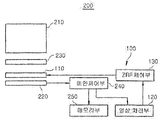
- FIG. 1 is a block diagram showing a digital photographing apparatus according to an embodiment of the present invention.
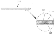
- FIG. 2 is a cross-sectional view illustrating ZRF in a digital photographing apparatus according to an embodiment of the present invention.
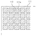
- FIG. 3 is a plan view illustrating ZRF in a digital photographing apparatus according to an embodiment of the present invention.
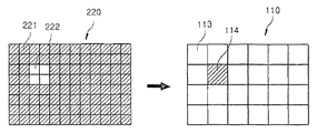
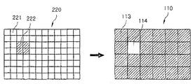
- FIG 4 and 5 are conceptual views for explaining the operation of the image quality improving apparatus according to an embodiment of the present invention.
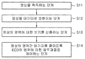
- FIG. 6 is a flowchart illustrating a method of improving image quality according to an embodiment of the present invention.
- the lens unit 210 collects light to form an image on the image sensor 120.
- the lens unit 210 may include a single lens or a plurality of lenses.
- the image sensor 220 is installed at the rear of the lens unit 210 and may be formed of a charge coupled device (CCD) or a complementary metal oxide semiconductor (CMOS), and an image focused on a chip surface is charged on an individual element. Accumulated in packets, these packets are output and converted into video for display. Meanwhile, an IR cut filter 230 may be installed at the front of the image sensor 220 to be positioned behind the lens unit 210.
- the IR cut filter 230 is a filter for blocking the infrared rays to improve the color sensor because the image sensor recognizes not only visible light but also infrared light, and reacts with light.
- the main controller 240 controls the image acquired by the image sensor 220 to be stored as data in the memory unit 250 according to an operation signal or a predetermined process by the operation unit, and outputs the data to the outside through the display unit as necessary. Can be controlled.
- the image quality improvement unit is installed to control the light transmittance irradiated to the image sensor 220 to reduce the brightness difference between the regions in the image obtained by the image sensor 220, which is an image quality improving apparatus according to an embodiment of the present invention ( 100). Therefore, the image quality improvement unit will be described instead with the image quality improvement apparatus 100 according to an embodiment of the present invention.
- the image quality improving apparatus 100 may include a zone collected reduction filter (ZRF), an image processor 120, and a ZRF controller 130.
- ZRF zone collected reduction filter
- the ZRF is installed between the lens unit 210 and the image sensor 220, transmits the light passing through the lens unit 210 to the image sensor 220, and is configured in a pixel manner.
- the light transmittance is adjusted for each area divided into a plurality of regions by an active array.
- ZRF consists of multiple pixels whose transmittance is controlled.
- the active array is controlled by the ZRF control unit 130, and may be a power supply circuit for supplying the power required for driving to each of the unit cells consisting of a single or multiple pixels, the size of the voltage for each of the unit cells, The application time is adjusted.
- the ZRF may have a light transmittance of the pixel controlled by the magnitude of the voltage applied by the ZRF controller 130, an application time of the voltage, and the like.
- the ZRF may be formed of an electrochromic display (ECD) 110.
- ECD electrochromic display
- Various display panels can be used, including an LCD that can adjust light transmittance for each region.
- the ECD 110 uses an element having a property of changing color when an electric current is applied, and the light transmittance of each pixel can be adjusted according to the supply time or size of the electric current.
- a region may be one unit in which light transmittance is controlled by the ZRF controller 130, may be formed of one or a plurality of pixels, and a partition may be set by the ZRF controller 130. .
- ZRF for example, ECD 110
- ECD 110 when the IR cut filter 230 is added between the lens unit 210 and the image sensor 220, between the IR cut filter 230 and the image sensor 220 220) can be installed to be biased toward the side.
- the ECD 110 may include a substrate 111 having a plurality of spaces 111a constituting pixels, and an electrochromic dye filled in each space 111a; 112).
- the substrate 111 may be provided with a conductive pattern for supplying a current to the electrochromic dye 112 filled in each of the spaces 111a by the control of the ZRF controller 130.
- the conductive pattern may be made of a light transmissive material.
- the ECD 110 is composed of a plurality of pixels, each pixel may be an electrochromic dye 112 filled in the space 111a of the substrate 111, the application of a current applied from the ZRF controller 130
- the light transmittance may be adjusted by time, size, or the like.
- the ECD 110 may include, for example, an electrochromic dye 112 of a single space 111a as a region forming a unit of light transmittance control by the ZRF controller 130, and as another example, a plurality of spaces 111a.
- Each region of the ECD 110 may be configured to correspond to a plurality of pixels in the image sensor 220, which is just one example and may be configured to correspond to a single pixel in the image sensor 220.
- the image processor 120 may process the image acquired by the image sensor 220 as data for calculating brightness for each of a plurality of divided regions, and output the data to the ZRF controller 130.
- the ZRF controller 130 calculates the brightness of a plurality of divided regions of the image from the data processed by the image processor 120 and reduces the brightness difference between the regions in the image. Control the light transmittance.
- the ZRF for example, the ECD 110 may be configured to be normally white, so that light may be transmitted when the voltage is not applied to the maximum luminance.
- the ZRF controller 130 may be configured such that the brightness difference of the area divided into a plurality of regions by arbitrary setting from the data processed by the image processor 120 may be reduced to a normal range, for example, deterioration in image quality.
- the control of the light transmittance of the region of the ECD 110 may be minimized, or the control of the light transmittance may not be performed.
- the minimum step may mean a step of minimizing the change in the light transmittance when setting the light transmittance of the area of the ECD 110 to a plurality of steps.
- the brightness difference between the areas in the image may be generated.
- the area of the ECD 110 corresponding to the area may be performed.
- the ZRF controller 130 extracts a light defective area from a region of an image acquired by the image sensor 220 and deviates from a predetermined brightness difference compared to the overall brightness.
- the correction region is extracted as a region contributing to the formation of ZRF, for example, the region which transmits the light irradiated to the correction region from the region of the ZRF, for example, the ECD 110, is extracted as the adjustment region, and the light transmittance of the adjustment region is It can be adjusted in inverse proportion to brightness.
- the overall brightness is the brightness of the whole image by the grade or numerical value
- the brightness degree of each image area is determined by the grade or the numerical value and averaged, or other methods of calculating and determining the brightness difference.
- the predetermined brightness difference may mean that an allowable range of the brightness difference between some or all areas and any one area is represented by a grade or a numerical value.
- the ZRF controller 130 includes light corresponding to light saturation as an area that is excessively brighter than the overall brightness due to a subject emitting strong light, for example, in the area of the image acquired by the image sensor 220.
- Defect area is extracted, and the correction area 222 is extracted as the area contributing to the formation of the light defect area among the areas 221 and 222 of the image sensor 220, and the correction area 222 is selected among the areas 113 and 114 of the ECD 110.
- the light transmitting area of the control area 114 may be extracted as the control area 114, and the light transmittance of the control area 114 may be adjusted to be lowered at a predetermined rate according to the brightness of the light defective area.
- the light defective area, the correction area 222, and the adjustment area 114 may be formed as a single area or a plurality of areas among the areas partitioned by the setting in the corresponding object. ) Shows four areas, and the control area 114 shows one area.
- the ZRF controller 130 may have a light deficiency corresponding to a light shortage as an area that is excessively dark compared to the overall brightness due to a dark subject caused by backlight, for example, in an area of an image acquired by the image sensor 220. Extracting a region, extracting a correction region 222 as a region contributing to the formation of a light defective region among the regions 221 and 222 of the image sensor 220, and correcting the region 222 among the regions 113 and 114 of the ECD 110.
- the area transmitting the light irradiated to the control area 114 may be extracted as the control area 114, and the light transmittance of the control area 114 may be adjusted to be increased at a set ratio according to the brightness of the light defective area.
- the image quality improving method according to an embodiment of the present invention is a method using the image quality improving apparatus 100 according to an embodiment of the present invention, and the ZRF, ECD 110, and image processing unit ( 120 and the embodiments of the ZRF control unit 130 and the like are applied in the same manner, the description of these configurations will be omitted.
- an image quality improving method includes an image sensor in which light is irradiated through a lens unit 210 and a zone collected reduction filter (ZRF), for example, an electrochromic display (ECD) 110.
- ZRF zone collected reduction filter
- ECD electrochromic display
- S11 an image is acquired.
- the image acquired by the image sensor 220 is processed by the image processor 120 as data (S12).
- the ZRF controller 130 calculates the brightness of a plurality of divided regions of the image from the data processed by the image processor 120 (S13).
- the CFR controller 130 controls the light transmittance of the region divided into a plurality of areas in the ZRF, for example, the ECD 110 to reduce the brightness difference between the regions in the image (S14).
- step S14 the light transmittance is adjusted by the ZRF controller 130 to extract a light defective area from the area of the image acquired by the image sensor 220 as an area deviating from a predetermined brightness difference compared to the overall brightness.
- the correction region is extracted from the region of the sensor 220 as a region contributing to the formation of the light defective region, and the region transmitting the light irradiated to the correction region from the region of the ZRF, for example, the ECD 110, is extracted as the adjusting region.
- the light transmittance of the adjustment region may be adjusted in inverse proportion to the brightness of the light defective region. A detailed description thereof has been given above with reference to FIGS. 4 and 5.
- the image can be obtained again by the image sensor 220, even before the light transmittance is corrected by the ECD 110 in advance, even in situations such as light saturation or light shortage, A clear and excellent color reproduction image can be obtained.
- the image quality improving method may be performed by receiving a signal for performing an image quality improving process according to, for example, a user's operation or a predetermined process. For example, as an advance procedure of shooting, It may be performed as a procedure after simultaneous or auto focusing. As another example, a signal for performing a photographing process may be received and automatically performed before photographing according to a user's manipulation or a predetermined process.
- the digital photographing apparatus having the same, and the image quality improving method according to the present invention, if there is an excessive brightness difference due to light saturation or lack of light for each region in one screen, it is installed between the lens unit and the image sensor.
- ZRF Zero collected Reduction Filter
- the light is installed between the lens unit and the image sensor and transmits the light passing through the lens unit to irradiate the image sensor, is configured in a pixel manner, the unit cell by placing an active array (active array) Zone collected Reduction Filter (ZRF), in which light transmittance is adjusted for each area divided into a plurality of regions by driving;
- ZRF Zone collected Reduction Filter
- An image processor which processes an image acquired by the image sensor as data;
- a ZRF controller configured to calculate brightness of a plurality of divided regions of the image from the data processed by the image processor and to control light transmittance of the region of the ZRF so as to reduce the brightness difference between the regions in the image.
- An image quality improving device is provided.
- the ZRF may be installed to be biased toward the image sensor between the IR cut filter installed between the lens unit and the image sensor and the image sensor.
- the ZRF is composed of an ECD (Electrochromic Display) composed of normally white, and the ZRF control unit includes a normal range of brightness differences of a plurality of regions divided from the data processed by the image processor. In the case of the inside, the control of the light transmittance for the region of the ECD can be minimized, or the control of the light transmittance may not be performed.
- ECD Electrode Display
- the ECD may have an area corresponding to a plurality of pixels as one unit in the image sensor.
- the ECD may include: a substrate having a plurality of spaces constituting pixels; And an electrochromic dye filled in each of the spaces.
- the ZRF controller extracts a light failure region as a region that deviates from a predetermined brightness difference from the overall brightness among the regions of the image, and extracts a correction region as a region that contributes to the formation of the light failure region among the regions of the image sensor. And extracting, as an adjusting region, a region that transmits light irradiated to the correction region from the region of the ZRF, and adjusting the light transmittance of the adjusting region in inverse proportion to the brightness of the light defective region.
- the lens unit is incident light; An image sensor installed at the rear of the lens unit; A main control unit controlling the image acquired by the image sensor to be stored in a memory unit; And an image quality improvement unit installed to control the light transmittance irradiated to the image sensor so as to reduce the brightness difference between the regions in the image acquired by the image sensor.
- the image quality improvement unit may further improve image quality according to an aspect of the present invention.
- a digital photographing apparatus which is an apparatus, is provided.
- the digital photographing apparatus may be any one of a portable digital camera, a CCTV camera, a camera of a portable electronic device, a web camera, a camera module of a vision inspector, and a camera module of a black box.
- ZRF Zone collected Reduction Filter
- the ZRF may be made of an electrochromic display (ECD).
- ECD electrochromic display
- the ZRF may include a substrate in which a plurality of spaces constituting pixels are partitioned; And an electrochromic dye filled in each of the spaces.
- the adjusting of the light transmittance may include extracting a light defective area as an area deviating from a predetermined brightness difference from the overall brightness among the areas of the image, and correcting it as an area contributing to the formation of the light defective area from the area of the image sensor.
- An area may be extracted, and an area of the ZRF that transmits light irradiated to the correction area may be extracted as an adjustment area, and the light transmittance of the adjustment area may be adjusted in inverse proportion to the brightness of the light defective area.
- the present invention is industrially applicable to digital photographing apparatus.
- IR cut filter 240 main control unit
Landscapes
- Engineering & Computer Science (AREA)
- Multimedia (AREA)
- Signal Processing (AREA)
- Physics & Mathematics (AREA)
- Nonlinear Science (AREA)
- General Physics & Mathematics (AREA)
- Optics & Photonics (AREA)
- Mathematical Physics (AREA)
- Chemical & Material Sciences (AREA)
- Crystallography & Structural Chemistry (AREA)
- Blocking Light For Cameras (AREA)
- Studio Devices (AREA)
Abstract
La présente invention concerne un appareil permettant d'améliorer une qualité d'image, un appareil de photographie numérique le comprenant, et un procédé permettant d'améliorer une qualité d'image. L'appareil permettant d'améliorer une qualité d'image comprend : un filtre de réduction collectée sur zone (ZRF) placé entre une unité de lentille et un capteur d'image pour permettre à une lumière qui est entrée dans l'unité de lentille de pénétrer et d'être irradiée sur le capteur d'image, et au moyen duquel le taux de pénétration de lumière de chaque zone divisée de la pluralité de zones est contrôlé ; une unité de traitement d'image pour convertir une image acquise par le capteur d'image en données ; et une unité de contrôle de ZRT pour calculer la luminosité d'une pluralité de zones, dans laquelle l'image a été divisée, au moyen des données traitées par l'unité de traitement d'image, et contrôler le taux de pénétration de lumière dans les zones ZRF de sorte à réduire le différentiel de luminosité entre les zones de l'image. Selon la présente invention, s'il existe un différentiel de luminosité excessif du à une saturation de lumière excessive ou une insuffisance de lumière pour chaque zone d'un écran unique, en contrôlant le taux de pénétration de lumière de chaque partie au moyen du filtre ZRF placé entre l'unité de lentille et le capteur d'image, il est possible d'acquérir une image d'une netteté et d'une reproduction de couleur d'excellente qualité.
Priority Applications (1)
| Application Number | Priority Date | Filing Date | Title |
|---|---|---|---|
| US15/310,446 US20170085765A1 (en) | 2014-05-21 | 2014-07-23 | Apparatus for improving image quality, digital photography apparatus having same, and method for improving image quality |
Applications Claiming Priority (2)
| Application Number | Priority Date | Filing Date | Title |
|---|---|---|---|
| KR1020140060780A KR101592409B1 (ko) | 2014-05-21 | 2014-05-21 | 화질 개선 장치, 이를 가지는 디지털 촬영 장치 및 화질 개선 방법 |
| KR10-2014-0060780 | 2014-05-21 |
Publications (1)
| Publication Number | Publication Date |
|---|---|
| WO2015178536A1 true WO2015178536A1 (fr) | 2015-11-26 |
Family
ID=54554184
Family Applications (1)
| Application Number | Title | Priority Date | Filing Date |
|---|---|---|---|
| PCT/KR2014/006672 Ceased WO2015178536A1 (fr) | 2014-05-21 | 2014-07-23 | Appareil permettant d'améliorer une qualité d'image, appareil de photographie numérique le comprenant, et procédé permettant d'améliorer une qualité d'image |
Country Status (3)
| Country | Link |
|---|---|
| US (1) | US20170085765A1 (fr) |
| KR (1) | KR101592409B1 (fr) |
| WO (1) | WO2015178536A1 (fr) |
Families Citing this family (6)
| Publication number | Priority date | Publication date | Assignee | Title |
|---|---|---|---|---|
| KR102261857B1 (ko) * | 2014-11-27 | 2021-06-07 | 삼성전자주식회사 | 이미지 센서 및 이를 적용한 이미지 획득 장치 및 방법 |
| US10048696B2 (en) | 2015-12-22 | 2018-08-14 | Uber Technologies, Inc. | Intelligent lens masking system for an autonomous vehicle |
| US11256013B2 (en) | 2019-03-27 | 2022-02-22 | Uatc, Llc | Dynamic matrix filter for vehicle image sensor |
| CN111736401B (zh) * | 2020-06-30 | 2021-11-16 | 联想(北京)有限公司 | 光学面板、图像采集设备及图像采集方法 |
| CN115720287B (zh) * | 2021-08-24 | 2026-02-06 | 浙江宇视科技有限公司 | 图像采集方法、装置、电子设备及介质 |
| EP4597205A1 (fr) * | 2024-02-05 | 2025-08-06 | Einride Autonomous Technologies AB | Agencement de caméra pour véhicules |
Citations (3)
| Publication number | Priority date | Publication date | Assignee | Title |
|---|---|---|---|---|
| JP2005167465A (ja) * | 2003-12-01 | 2005-06-23 | Fuji Photo Film Co Ltd | デジタルカメラ及びデジタルカメラの撮像方法 |
| KR100708938B1 (ko) * | 2005-11-07 | 2007-04-17 | 삼성전기주식회사 | 액정 광량 조절장치 및 이를 이용한 카메라 모듈 및 액정광량 조절장치를 이용한 카메라 |
| US20130300986A1 (en) * | 2012-05-11 | 2013-11-14 | Industry-Academic Cooperation Foundation Yonsei University | Wire grid polarizer and method for fabricating thereof, liquid crystal display panel and liquid crystal display device having the same |
Family Cites Families (1)
| Publication number | Priority date | Publication date | Assignee | Title |
|---|---|---|---|---|
| JP2005110163A (ja) * | 2003-10-02 | 2005-04-21 | Olympus Corp | カメラ |
-
2014
- 2014-05-21 KR KR1020140060780A patent/KR101592409B1/ko active Active
- 2014-07-23 WO PCT/KR2014/006672 patent/WO2015178536A1/fr not_active Ceased
- 2014-07-23 US US15/310,446 patent/US20170085765A1/en not_active Abandoned
Patent Citations (3)
| Publication number | Priority date | Publication date | Assignee | Title |
|---|---|---|---|---|
| JP2005167465A (ja) * | 2003-12-01 | 2005-06-23 | Fuji Photo Film Co Ltd | デジタルカメラ及びデジタルカメラの撮像方法 |
| KR100708938B1 (ko) * | 2005-11-07 | 2007-04-17 | 삼성전기주식회사 | 액정 광량 조절장치 및 이를 이용한 카메라 모듈 및 액정광량 조절장치를 이용한 카메라 |
| US20130300986A1 (en) * | 2012-05-11 | 2013-11-14 | Industry-Academic Cooperation Foundation Yonsei University | Wire grid polarizer and method for fabricating thereof, liquid crystal display panel and liquid crystal display device having the same |
Also Published As
| Publication number | Publication date |
|---|---|
| KR20150134019A (ko) | 2015-12-01 |
| KR101592409B1 (ko) | 2016-02-05 |
| US20170085765A1 (en) | 2017-03-23 |
Similar Documents
| Publication | Publication Date | Title |
|---|---|---|
| WO2014189232A1 (fr) | Capteur électronique et méthode de commande de celui-ci | |
| US8049801B2 (en) | Image sensor and imaging apparatus | |
| EP3349433B1 (fr) | Système de commande, dispositif d'imagerie et programme | |
| EP1583356A1 (fr) | Dispositif de traitement d'images et programme de traitement d'images | |
| CN101852675B (zh) | 一种测试数码相机各个成像区域分辨率的方法 | |
| WO2021022592A1 (fr) | Appareil de compensation d'imagerie, procédé de compensation d'imagerie et application associée | |
| CN100370811C (zh) | 数字静态照相装置、摄像装置和信息终端装置及其活点量计算方法 | |
| CN101840576B (zh) | 一种可视化的测试数码相机各个成像区域分辨率的方法 | |
| CN107079083A (zh) | 一种拍照方法、拍照装置和终端 | |
| CN105191285A (zh) | 固体摄像器件、电子装置、镜头控制方法和摄像模块 | |
| CN103905731B (zh) | 一种宽动态图像采集方法及系统 | |
| KR101592409B1 (ko) | 화질 개선 장치, 이를 가지는 디지털 촬영 장치 및 화질 개선 방법 | |
| US6831687B1 (en) | Digital camera and image signal processing apparatus | |
| CN115118858B (zh) | 图像传感器、图像采集方法、装置、电子设备及储存介质 | |
| US7791640B2 (en) | Electronic camera and image generating apparatus generating stereo image | |
| CN107835351B (zh) | 一种双摄像头模组以及终端 | |
| CN107995396B (zh) | 一种双摄像头模组以及终端 | |
| US20210049427A1 (en) | Image processing apparatus, image processing method, and image processing system | |
| JP2015192152A (ja) | ホワイトバランス調整装置及びホワイトバランス調整方法並びに撮影装置 | |
| WO2015178534A1 (fr) | Appareil d'amélioration de la qualité d'image, appareil de photographie numérique muni de celui-ci, et procédé d'amélioration de la qualité d'image | |
| KR101613434B1 (ko) | 디지털 촬영장치의 화질 개선 장치 및 화질 개선 방법 | |
| KR101613433B1 (ko) | 디지털 촬영장치의 화질 개선 장치 및 화질 개선 방법 | |
| US10104285B2 (en) | Method and apparatus for high resolution digital photography from multiple image sensor frames | |
| WO2016003106A2 (fr) | Capteur matriciel pour caméra à ouvertures multiples | |
| KR101139661B1 (ko) | 촬상 장치 및 촬상 방법 |
Legal Events
| Date | Code | Title | Description |
|---|---|---|---|
| 121 | Ep: the epo has been informed by wipo that ep was designated in this application |
Ref document number: 14892832 Country of ref document: EP Kind code of ref document: A1 |
|
| WWE | Wipo information: entry into national phase |
Ref document number: 15310446 Country of ref document: US |
|
| NENP | Non-entry into the national phase |
Ref country code: DE |
|
| 122 | Ep: pct application non-entry in european phase |
Ref document number: 14892832 Country of ref document: EP Kind code of ref document: A1 |