WO2015178593A1 - 물체 전방위 촬영 3차원 실물화상기 - Google Patents
물체 전방위 촬영 3차원 실물화상기 Download PDFInfo
- Publication number
- WO2015178593A1 WO2015178593A1 PCT/KR2015/004167 KR2015004167W WO2015178593A1 WO 2015178593 A1 WO2015178593 A1 WO 2015178593A1 KR 2015004167 W KR2015004167 W KR 2015004167W WO 2015178593 A1 WO2015178593 A1 WO 2015178593A1
- Authority
- WO
- WIPO (PCT)
- Prior art keywords
- support
- camera
- photographing
- dimensional
- cameras
- Prior art date
- Legal status (The legal status is an assumption and is not a legal conclusion. Google has not performed a legal analysis and makes no representation as to the accuracy of the status listed.)
- Ceased
Links
Images
Classifications
-
- G—PHYSICS
- G03—PHOTOGRAPHY; CINEMATOGRAPHY; ANALOGOUS TECHNIQUES USING WAVES OTHER THAN OPTICAL WAVES; ELECTROGRAPHY; HOLOGRAPHY
- G03B—APPARATUS OR ARRANGEMENTS FOR TAKING PHOTOGRAPHS OR FOR PROJECTING OR VIEWING THEM; APPARATUS OR ARRANGEMENTS EMPLOYING ANALOGOUS TECHNIQUES USING WAVES OTHER THAN OPTICAL WAVES; ACCESSORIES THEREFOR
- G03B35/00—Stereoscopic photography
- G03B35/16—Stereoscopic photography by sequential viewing
Definitions
- the present invention relates to a three-dimensional physical imager of an object omnidirectional photographing, and more specifically, to a three-dimensional image of an object to be observed in three dimensions and to correct it to be implemented in three dimensions by the conventional two-dimensional physical imager three-dimensional image
- the present invention relates to an object omni-directional three-dimensional physical imager capable of photographing and forming a data, as well as perfectly photographing the lower surface of the object and measuring the weight of the object.
- the real imager is formed so that the object can be photographed by the camera formed on the upper part in the state placed on the base for presentation or explanation and sent to another image device.
- the real imager is used to describe a target object such as education, business announcement, etc. in real time with an image device or to store it as data.
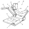
- a conventional real imager is provided with an operation button 1 at the front of the case 9, a target object 2 at the center thereof, and a protrusion 4 having the rotation shaft 3 installed at the rear side thereof. It is integrally coupled, the support shaft 5 is protruded in the center of the rotary shaft 3, the fastening piece 7 for adjusting the height of the imager 6 is protruded at the end thereof, the upper end of the support shaft 5
- the rotating part 11 for rotating the imager 6 in which the camera 10 is installed therein is spoken, and both ends of the protrusion part 4 are formed in a structure in which the lighting device 8 is installed.
- the real imager places the rotating part 11 on the support shaft 7 coupled to the upper portion of the rotation shaft 3, After adjusting the position of the object 2 in order to photograph the object 2, it is formed to adjust the operation button 1 to photograph.
- the conventional real imager has the following problems.
- the three-dimensional photographing apparatus can be stored as data while accurately measuring the object, but it is difficult to use because the price is expensive and the amount of data is large because a separate device is needed to measure the depth or size.
- the present invention was developed in order to solve the above problems, to be used for presentation in schools, companies, etc., or to easily convert the object into three-dimensional data,
- a base having an image transmission and image processing apparatus formed therein;
- a photographing unit in which a semicircular support is formed on one side of the base, and a plurality of cameras are formed on the concave surface of the support, and a plurality of lights are formed to be spaced apart from each camera;
- a disc support projecting to both sides of the center portion of the support of the photographing unit is formed, characterized in that consisting of the object support portion formed of a disc of a transparent material which is fixed to one side to the disc support to be rotated by a motor do.
- weight data can be obtained without additional equipment and used as ancillary data when measuring volume and density.
- FIG. 1 is a perspective view of a conventional real imager.
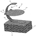
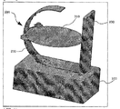
- Figure 2 is a perspective view of the object omnidirectional photographing three-dimensional real image formed by the preferred embodiment of the present invention.
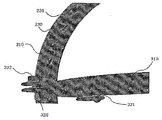
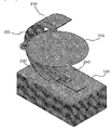
- Figure 3 is a partially enlarged perspective view of the object omnidirectional photographing three-dimensional imager formed in a preferred embodiment of the present invention.
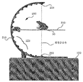
- Figure 4 is a side view of the object omnidirectional photographing three-dimensional physical image formed by the preferred embodiment of the present invention.
- Figure 5 is a perspective view of the corresponding surface formed on the object omnidirectional photographing three-dimensional physical imager formed in a preferred embodiment of the present invention.
- FIG. 6 is a conceptual perspective view of a lighting plate and a sliding panel mounted on the object omnidirectional photographing three-dimensional physical imager formed by a preferred embodiment of the present invention.
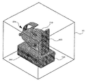
- Figure 7 is a conceptual perspective view of the protective film installed on the object omnidirectional three-dimensional physical imager formed by a preferred embodiment of the present invention.
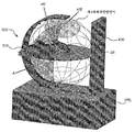
- FIG. 8 is a conceptual perspective view showing a photographing surface of the object of the object omnidirectional photographing three-dimensional physical imager formed by a preferred embodiment of the present invention.
- the image processing apparatus 110 includes a base 100 formed therein;
- a semi-convex support 210 is formed at one side of the upper end of the base 100, a plurality of cameras 220 are formed on the concave surface of the support 210, and a plurality of cameras 220 are spaced apart from each of the cameras 220.
- the disc support 320 is formed to protrude to both sides of the center portion of the support 210 of the photographing unit 200, one side is fixed to the disc support 320 is formed to be rotatable by the motor 322 It is composed of the object support 300 is formed of a disc (310).
- An image processing apparatus 110 is formed in the base 100, and the image processing apparatus 110 is rotated by a disc 310 by a motor 322.
- the camera 220 is formed to photograph and then convert the photographed images in order to create 3D data, and to transmit and store the 3D data.
- the photographing unit 200 is fixed to the upper end of the base 100 is formed with a support 210 is formed in a semi-circular convex shape to one side.
- a plurality of cameras 220 are formed on the concave surface of the support 210, and each camera 220 is formed to photograph the direction of the center of the disc 310.
- Each camera 220 has a first camera 221 is formed to completely photograph the upper surface of the disc 310, the second camera 222 is formed at the lower end to correspond to the first camera 221, A plurality of polygonal photographing cameras 223 are formed between the first camera 221 and the second camera 222 along the concave surface of the support 210, and the number of the polygonal photographing cameras 223 is a disc. The same number of cameras 223 are formed around 310.
- Each of the cameras 220 is formed to be photographed in an array, that is, arranged in a longitudinal direction, so as to photograph from the upper surface of the object 50 to the lower surface along the side surface.
- each camera 220 photographs the object 50 through the photographing surface A, and such data. Analyze the photographing one surface of the hardness of the object 50.
- Images taken by the first camera 221 and the second camera 222 are used as a means of checking whether the object 50 is located in the center, respectively, if the first photographed surface and the second photographed surface are the centers. If there is shaking, correction data is applied to all cameras.
- each of the cameras 220 may be adjusted to be 3 to 10 cm above the bottom surface of the object 50 to prevent light reflected from the disc 310, or to be aligned with the upper center plane of the disc. .
- a sliding panel 240 is formed in the center of the concave surface of the support 210 to be slid in the longitudinal direction by a motor in the longitudinal direction, and the sliding panel 240 has a camera 220, that is, a first camera ( 221, the second camera 222, and the polygon camera 223 are respectively installed.
- the camera 220 when the camera 220 is installed in the center of the concave surface of the support 210 in the longitudinal direction is installed on the upper surface of the sliding panel 240, the camera while the sliding panel 240 is transferred in the longitudinal direction It is formed to be transported at the same time.
- the camera 220 is moved up and down in the longitudinal direction, so that the surface of the object 50 can be photographed at a plurality of angles in the latitude direction, so that more accurate shooting is possible. Do.
- Each of the lights 230 is configured to be spaced apart from each of the cameras 220, each of the lights 230 may be formed so that the distance can be adjusted in the direction of the target object (50).
- a light diffusion plate is formed in front of each of the lights 230 so that light is evenly sprayed to reduce reflection as much as possible.
- Each of the lights 230 may be formed separately from the left and right sides of the support 210, and is formed to minimize shadows on the object 50 and may be configured to adjust brightness.
- the illumination 230 may be formed as a lighting plate 235 while maintaining the same curved surface as the support 210 on both sides of the support 210, it is formed to be spaced apart from the camera 220, the object by the light diffusion plate 50 can be formed so as to irradiate light without a shadow.
- Both the illumination 230 and the illumination plate 235 can adjust the brightness, and is formed to adjust the brightness according to the color or characteristics of the object 50.
- a corresponding surface 400 is formed on a corresponding surface of the support 210 at an upper end of the base 100 as shown in FIG. 5, and the corresponding surface 400 may be a background screen when each camera 220 is photographed. It is formed so as to be configured as a blue screen (bluescreen) to store the three-dimensional data of the target object 50, or is formed so as to put the background screen when sent to the image device.
- blue screen bluescreen
- the object support 300 is composed of a disc support 320 which is fixed to both sides of the center of the support 210, and a disc 310 supported by each disc support 320.
- the disc 310 is formed to put the object 50, it is formed of a transparent material, it is formed of a material that can minimize the reflection of light by illumination.
- a pressure sensor is installed between the disc 310 and the disc support 320 to measure the weight of the object 50 placed on the disc 310.
- the disc 310 may be formed to move the center of rotation to correct the position of the target object 50, the center of rotation of the disc 310 can be matched with the center of rotation of the target object 50 By moving the position so as to rotate around the axis connecting the first camera 221 and the second camera 222.
- the object 50 is positioned in the center of the disc 310 to prepare for photographing. At this time, it is important that the center of the object 50 is placed so that the axis is located on the axis connecting the first camera 221 and the second camera 222.
- the position correction is performed by correcting the images photographed by the first camera 221 and the second camera 220.
- the above process is continuously performed to form three-dimensional data about the object 50 by connecting the respective surfaces.
- the saturation of the shadow in the image of the photographed surface is measured to apply a partial depth.
- each camera 220 is a target object 50.
- the camera will shoot different latitude planes of the camera, allowing for more precise shooting.
- the object is completely three-dimensional data in one shot so that the user can move the object. It can be used as 3D data because it can photograph only the appearance of the object and make it completely 3D data in an image, and it can be used as 3D data, without accurately measuring the dimensions of the object. It is possible to obtain three-dimensional data and weight data that can be visually checked only by photographing the exterior, so that the operation can be performed at a relatively low price.
Landscapes
- Physics & Mathematics (AREA)
- General Physics & Mathematics (AREA)
- Studio Devices (AREA)
- Image Input (AREA)
Abstract
본 발명은 물체 전방위 촬영 3차원 실물화상기에 관한 것으로, 더욱 상세하게는 관찰 대상물체를 전방위로 3차원으로 촬영하고 이를 보정하여 3차원으로 구현할 수 있도록 함으로써 종래의 2차원적인 실물 화상기를 3차원 영상데이터로 촬영 형성할 수 있도록 할 뿐만 아니라 대상물체의 하면까지 완벽하게 촬영할 수 있고, 대상물체의 무게를 측정할 수 있는 물체 전방위 3차원 실물화상기에 관한 것이다.
Description
본 발명은 물체 전방위 촬영 3차원 실물화상기에 관한 것으로, 더욱 상세하게는 관찰 대상물체를 전방위로 3차원으로 촬영하고 이를 보정하여 3차원으로 구현할 수 있도록 함으로써 종래의 2차원적인 실물 화상기를 3차원 영상데이터로 촬영 형성할 수 있도록 할 뿐만 아니라 대상물체의 하면까지 완벽하게 촬영할 수 있고, 대상물체의 무게를 측정할 수 있는 물체 전방위 3차원 실물화상기에 관한 것이다.
일반적으로 실물 화상기는 발표나 설명을 위해서 베이스에 놓은 상태에서 상부에 형성된 카메라로 대상물을 촬영하여 다른 영상장치로 송출할 수 있도록 형성된 것이다.
상기 실물 화상기는 교육, 사업발표 등의 대상물체를 영상장치로 실시간으로 보이면서 설명하거나 이를 데이타로 저장하기 위해서 사용된다.
종래의 실물 화상기는 도 1과 같이 케이스(9)의 전방에는 조작버튼(1)이 설치되고, 중앙에는 대상물체(2)가 위치되며 후방에는 내측으로 회전축(3)이 설치된 돌출부(4)가 일체로 결합되며, 상기 회전축(3)의 중앙에는 지지축(5)이 연설되어 그 단부에는 화상기(6)의 높이를 조정하는 체결편(7)이 연설되고, 상기 지지축(5)의 상단부에는 내부에 카메라(10)가 설치된 화상기(6)를 회전하도록 하는 회전부(11)가 연설되며, 상기 돌출부(4)의 양단부에는 조명장치(8)가 설치되는 구조로 형성된다.
상기 실물 화상기는, 케이스(9)의 상단에 대상물체(2)를 위치하면 회전축(3)의 상부에 결합된 지지축(7)상에 회전부(11)를 위치하고, 연설된 화상기(6)가 대상물체(2)를 촬영하기 위해서 대상물체(2)의 위치를 조정한 후, 조작버튼(1)을 조정하여 촬영처리하도록 형성된다.
종래의 실물 화상기에 관한 기술은 대한민국 특허청 등록특허공보 제0294909호, 제1012706호 등에 개시된 바 있다.
최근에는 3차원으로 대상물체를 전방위로 촬영하고, 대상물체의 실제 치수와 형태를 완벽하게 측정하여 이를 3차원 프린터기로 재현해 낼 수 있는 3차원촬영장치가 개발되어 있다.
그러나, 종래의 실물 화상기는 다음과 같은 문제점이 있었다.
(1) 대상물체의 상면을 2차원으로 촬영하기 때문에 사용자가 대상물체를 화상기를 회전시키거나 대상물체를 옮기면서 설명하여야 한다.
(2) 대상물체를 촬영하더라도 이를 데이터로 활용하는데에는 한계가 있어서 영상장치로 송출하는 것에 만족해야 한다.
(3) 3차원촬영장치는 대상물체를 정확히 측정하면서 데이터로 저장할 수 있으나 깊이나 크기를 측정하기 위해서 별도의 장치가 필요하여 가격이 고가이고 데이터의 양이 많아서 사용하기가 어렵다.
본 발명은 상기한 문제점들을 해결하고, 학교나 기업 등에서 발표용으로 사용하거나, 대상물체를 3차원 데이터로 쉽게 전환할 수 있도록 하기 위해서 개발된 것으로,
영상송출 및 영상처리장치가 내부에 형성된 베이스와;
상기 베이스의 상단에 일측으로 볼록한 반원형상의 지지대가 형성되고, 상기 지지대의 오목한면에는 다수개의 카메라가 형성되며, 상기 각 카메라와 이격되도록 다수개의 조명이 형성되는 촬영부와;
상기 촬영부의 지지대의 가운데 부분의 양측으로 돌출되는 원판지지대가 형성되고, 상기 원판지지대에 일측이 고정되어 모터에 의해서 회전가능하도록 형성되는 투명한 재질의 원판으로 형성되는 대상물체지지부로 구성되는 것을 특징으로 한다.
본 발명의 물체 전방위 촬영 3차원 실물화상기에 의하면 다음과 같은 효과가 발생한다.
(1) 대상물체의 상면, 양측면, 후면 및 저면까지 전방위로 촬영이 이루어지기 때문에 한 번의 촬영으로 대상물체가 완전하게 3차원 데이터화되므로 사용자는 대상물체를 이동시키거나 별도의 조작을 하지 않아도 된다.
(2) 대상물체의 외관만을 촬영하고 이를 이미지 적으로 완전하게 3차원 데이터로 만들 수 있으므로 3차원데이터로 활용할 수 있다.
(3) 대상물체의 치수를 정확하게 측정하지 않고, 대상물체의 외관의 촬영만으로 눈으로 확인할 수 있는 3차원데이터를 얻을 수 있으므로 비교적 저렴한 가격으로 운용이 가능하다.
(4) 대상물체의 무게를 측정할 수 있도록 함으로써 별도의 장비없이도 무게데이터를 얻어 부피 및 밀도의 측정시 보조데이터로 활용할 수 있다.
도 1은 종래의 실물 화상기의 사시도.
도 2는 본 발명의 바람직한 실시예로 형성된 물체 전방위 촬영 3차원 실물화상기의 사시도.
도 3은 본 발명의 바람직한 실시예로 형성된 물체 전방위 촬영 3차원 실물화상기의 부분 확대사시도.
도 4는 본 발명의 바람직한 실시예로 형성된 물체 전방위 촬영 3차원 실물화상기의 측면도.
도 5는 본 발명의 바람직한 실시예로 형성된 물체 전방위 촬영 3차원 실물화상기에 대응면을 형성한 사시도.
도 6은 본 발명의 바람직한 실시예로 형성된 물체 전방위 촬영 3차원 실물화상기에 조명판과 슬라이딩패널을 장착한 개념 사시도.
도 7은 본 발명의 바람직한 실시예로 형성된 물체 전방위 촬영 3차원 실물화상기에 보호막을 설치한 개념 사시도.
도 8은 본 발명의 바람직한 실시예로 형성된 물체 전방위 촬영 3차원 실물화상기의 대상물체의 촬영면을 나타낸 개념 사시도.
본 발명은 영상처리장치(110)가 내부에 형성된 베이스(100)와;
상기 베이스(100)의 상단에 일측으로 볼록한 반원형상의 지지대(210)가 형성되고, 상기 지지대(210)의 오목한 면에 다수개의 카메라(220)가 형성되며, 상기 각 카메라(220)와 이격되도록 다수개의 조명(230)이 형성되는 촬영부(200)와;
상기 촬영부(200)의 지지대(210)의 가운데 부분의 양측으로 돌출되는 원판지지대(320)가 형성되고, 상기 원판지지대(320)에 일측이 고정되어 모터(322)에 의해서 회전가능하도록 형성되는 원판(310)으로 형성되는 대상물체지지부(300)로 구성된다.
상기 베이스(100)에는 영상처리장치(110)가 형성되는데, 상기 영상처리장치(110)는 모터(322)에 의한 원판(310)의 회전으로 대상물체(50)가 일정 각도씩 회전할 때 각 카메라(220)에 촬영되는 영상을 차례로 촬영한 후 변환하여 3차원데이터를 만들고 이를 송출 및 저장할 수 있도록 형성된다.
상기 촬영부(200)는 베이스(100)의 상단에 고정되고 일측으로 볼록하게 반원형상으로 형성되는 지지대(210)가 형성된다.
상기 지지대(210)의 오목한 면에는 다수개의 카메라(220)가 형성되는데, 상기 각 카메라(220)는 원판(310)의 가운데를 방향을 촬영할 수 있도록 형성된다.
상기 각 카메라(220)는 원판(310)의 상면을 완전하게 촬영하는 제1카메라(221)가 형성되고, 상기 제1카메라(221)와 대응되도록 최하단에 제2카메라(222)가 형성되며, 상기 지지대(210)의 오목한 면을 따라서 제1카메라(221)와 제2카메라(222)의 사이에 다수개의 다각촬영카메라(223)가 형성되는데, 상기 각 다각촬영카메라(223)의 개수는 원판(310)을 중심으로 동일한 개수의 카메라(223)가 각각 형성된다.
상기 각 카메라(220)는 대상물체(50)의 상면에서 측면을 따라서 하면까지 촬영할 수 있도록 배열 즉 경도방향으로 배열되어 촬영할 수 있도록 형성된다.
도 8을 참조하면, 원판(310)이 대상물체(50)를 일정각도를 회전하고 정지할 때마다 각 카메라(220)는 촬영면(A)을 통해서 대상물체(50)를 촬영하고, 이러한 데이터를 분석하여 대상물체(50)의 경도의 일면을 촬영한다.
상기 제1카메라(221)와 제2카메라(222)가 촬영한 영상은 각각 대상물체(50)가 가운데에 위치한 것인지를 확인하는 수단으로 활용되는데, 만약 첫번째 촬영한 면과 두번째 촬영한 면이 중심의 흔들림이 있으면 이를 보정하는 보정데이터를 모든 카메라에 적용한다.
상기 각 카메라(220)의 포커스(focus)는 원판(310)에서 반사되는 빛을 받아들이지 못하도록 대상물체(50)의 바닥면에서 3 ~10 cm 위쪽에 맞추거나, 원판의 상부 중심면에 맞출 수 있다.
상기 지지대(210)의 오목한 면의 가운데에 길이방향으로 모터에 의해서 길이방향으로 슬라이딩될 수 있도록 슬라이딩패널(240)이 형성되고, 상기 슬라이딩패널(240)에 카메라(220) 즉, 제1카메라(221), 제2카메라(222) 및 다각촬영카메라(223)들이 각각 설치된다.
즉, 상기 지지대(210)의 오목한 면의 가운데에 길이방향으로 카메라(220)가 설치될 때 슬라이딩패널(240)의 상면에 설치되고, 상기 슬라이딩패널(240)이 길이방향으로 이송되면서 카메라들도 동시에 이송될 수 있도록 형성된다.
상기와 같이 슬라이딩패널(240)의 상단에 카메라들이 설치되면 카메라(220)가 길이방향으로 상하로 이송되면서 대상물체(50)의 표면을 위도방향으로 다수 각도로 촬영가능하기 때문에 보다 정밀한 촬영이 가능하다.
상기 각 조명(230)은 각 카메라(220)와 이격되어 각각 구성되는데, 상기 각 조명(230)은 대상물체(50) 방향으로 거리조절이 가능하도록 형성될 수 있다.
상기 각 조명(230)의 전방에는 광확산판을 형성하여 빛이 골고루 분사되도록 하여 반사를 최대한 줄일 수 있도록 형성된다.
상기 각 조명(230)은 지지대(210)의 좌우에 별도로 위치하여 형성될 수 있는데 대상물체(50)에 그림자를 최소화할 수 있도록 형성되고, 밝기를 조절할 수 있도록 형성된다.
상기 조명(230)은 지지대(210)의 양측으로 지지대(210)와 동일한 곡면을 유지하면서 조명판(235)으로 형성될 수 있는데, 카메라(220)와 이격되도록 형성되어 광확산판에 의해서 대상물체(50)에 그림자 없이 조명을 조사할 수 있도록 형성될 수 있다.
상기 조명(230)과 조명판(235)은 모두 그 밝기를 조절할 수 있고, 대상물체(50)의 색상이나 특징에 따라서 광도를 조절할 수 있도록 형성된다.
상기 베이스(100)의 상단에 지지대(210)의 대응되는 면에 도 5와 같이 대응면(400)이 형성되는데, 상기 대응면(400)는 각 카메라(220)가 촬영할 때 배경화면이 될 수 있도록 형성되고, 블루스크린(bluescreen)으로 구성하여 대상물체(50)의 3차원 데이터를 저장하거나, 영상장치로 송출할 때 배경화면을 넣을 수 있도록 형성된다.
상기 대상물체지지부(300)는 지지대(210)의 가운데의 양측에 고정되는 원판지지대(320)와, 각 원판지지대(320)에 의해서 지지되는 원판(310)으로 구성된다.
상기 원판(310)은 대상물체(50)를 올려놓을 수 있도록 형성되는데, 투명한 재질로 형성되되, 조명에 의한 빛의 반사를 최소화할 수 있는 재질로 형성된다.
상기 원판(310)과 원판지지대(320)의 사이에 압력센서를 설치하여 원판(310)에 올려지는 대상물체(50)의 무게를 측정할 수 있도록 형성된다.
상기 원판(310)은 대상물체(50)의 위치를 보정할 수 있도록 회전중심을 옮길 수 있도록 형성될 수 있는데, 상기 원판(310)의 회전중심은 대상물체(50)의 회전중심과 일치시킬 수 있도록 위치를 이동시켜 제1카메라(221)과 제2카메라(222)를 잇는 축을 중심으로 회전할 수 있도록 이동된다.
이하, 본 발명의 바람직한 실시예로 형성된 물체 전방위 촬영 3차원 실물화상기의 작동 및 영상촬영방법 등을 설명하면 다음과 같다.
본 발명의 물체 전방위 촬영 3차원 실물화상기를 사용하여 대상물체(50)를 촬영하기 위해서는 전체를 덮을 수 있는 도 7과 같이 보호막(60)을 형성하는 것이 적당한데, 조명(230)의 효과를 최대한으로 높이기 위해서 사용한다.
상기 대상물체(50)를 원판(310)의 가운데에 위치하고 촬영을 준비한다. 이때, 대상물체(50)의 정가운데 축이 제1카메라(221)와 제2카메라(222)를 연결하는 축에 위치하도록 올려놓는 것이 중요하다.
그러나, 정확하게 위치하지 않더라도 제1카메라(221)와 제2카메라(220)에 촬영되는 영상의 보정을 통해서 위치보정이 이루어진다.
상기와 같이 대상물체(50)를 위치한 상태에서 첫번째 촬영을 하면 대상물체(50)의 일면이 상부에서 측면 및 하부까지 촬영된다(a면촬영).
이후, 원판(310)이 회전하여 정해진 각도로 회전하면 대상물체(50)의 연속된 다른면이 촬영부(200)에 위치하게 되고 이때 두번째 촬영을 한다(b면촬영).
상기와 같은 과정을 연속적으로 수행하여 각 면을 연결하여 대상물체(50)에 대한 3차원 데이터를 구성한다.
이때, 촬영된 면의 영상에서 음영의 채도를 측정하여 일부깊이를 측정하여 적용한다.
촬영된 각 경도상의 면을 연결하여 대상물체(50)에 대한 3차원 데이터를 획득하고 이를 그림파일로 저장할 수 있음은 물론 고해상도 카메라(30)를 사용하여 축소, 확대가 가능할 수 있도록 제공된다.
상기 카메라(220)가 슬라이딩패널(240)에 의해서 형성되면, 최초 제1카메라(221)와 제2카메라(222)를 대상물체(50)에 수직하게 놓은 상태에서 원판(310)을 회전시켜 촬영하고 데이터를 획득한 상태에서, 슬라이딩패널(240)을 지지대(210)의 내주연을 따라 일정각도로 이동시켜 다시 원판(310)을 회전시켜서 촬영하면, 각 카메라(220)가 대상물체(50)의 다른 위도상의 면을 촬영하게 되므로 보다 정밀한 촬영이 가능해 진다.
또한, 카메라(220)의 설치개수를 줄일 수 있으면서도 촬영을 정밀하게 하기 위해서는, 슬라이딩패널(240)의 이동을 활용하여 여러 번 촬영하는 방법으로 해결할 수 있다.
본 발명의 물체 전방위 촬영 3차원 실물화상기에 의하면 대상물체의 상면, 양측면, 후면 및 저면까지 전방위로 촬영이 이루어지기 때문에 한 번의 촬영으로 대상물체가 완전하게 3차원 데이터화되므로 사용자는 대상물체를 이동시키거나 별도의 조작을 하지 않아도 되고, 대상물체의 외관만을 촬영하고 이를 이미지 적으로 완전하게 3차원 데이터로 만들 수 있으므로 3차원데이터로 활용할 수 있으며, 대상물체의 치수를 정확하게 측정하지 않고, 대상물체의 외관의 촬영만으로 눈으로 확인할 수 있는 3차원데이터와 무게데이터를 얻을 수 있으므로 비교적 저렴한 가격으로 운용이 가능한 등의 효과가 발생한다.
본 발명은 바람직한 실시예를 중심으로 기술되었지만, 당업자라면 이러한 기재로부터 후술하는 특허청구범위에 의해 포괄되는 본 발명의 범주를 벗어남이 없이 다양한 변형이 가능하다는 것은 명백하다.
Claims (7)
- 영상처리장치가 내부에 형성된 베이스와;상기 베이스의 상단에 일측으로 볼록한 반원형상의 지지대가 형성되고, 상기 지지대의 오목한 면에 다수개의 카메라가 형성되며, 상기 각 카메라와 이격되도록 다수개의 조명이 형성되는 촬영부와;상기 촬영부의 지지대의 가운데 부분의 양측으로 돌출되는 원판지지대가 형성되고, 상기 원판지지대에 일측이 고정되어 모터에 의해서 회전가능하도록 형성되는 원판으로 형성되는 대상물체지지부로 구성되는 것을 특징으로 하는 물체 전방위 촬영 3차원 실물화상기.
- 제 1항에 있어서,상기 촬영부의 각 카메라는 원판의 상면을 완전하게 촬영하는 제1카메라가 형성되고, 상기 제1카메라와 대응되도록 최하단에 제2카메라가 형성되며, 상기 지지대의 오목한 면을 따라서 제1카메라와 제2카메라의 사이에 다수개의 다각촬영카메라가 형성되는데, 상기 각 다각촬영카메라의 개수는 원판을 중심으로 동일한 개수의 카메라가 각각 형성되는 것을 특징으로 하는 물체 전방위 촬영 3차원 실물화상기.
- 제 1항 또는 제 2항에 있어서,상기 지지대의 오목한 면의 가운데에는 지지대의 오목한 면을 따라 이동가능한 슬라이딩패널이 형성되고, 상기 슬라이딩패널에는 카메라와 조명이 형성되는 것을 특징으로 하는 물체 전방위 촬영 3차원 실물화상기.
- 제 1항에 있어서,상기 베이스의 상단에 지지대의 대응되는 위치에 대응면이 형성되는 것을 특징으로 하는 물체 전방위 촬영 3차원 실물화상기.
- 제 1항에 있어서,상기 원판지지대에는 무게를 측정할 수 있는 압력센서가 형성되는 것을 특징으로 하는 물체 전방위 촬영 3차원 실물화상기.
- 제 1항에 있어서,상기 촬영부의 지지대의 양측에는 조명판이 형성되고, 상기 조명판은 밝기가 조절가능하도록 형성된 것을 특징으로 하는 물체 전방위 촬영 3차원 실물화상기
- 제 1항에 있어서,상기 촬영부와 대상물체지지부를 중심으로 이격되게 보호막이 설치되는 것을 특징으로 하는 물체 전방위 촬영 3차원 실물화상기
Applications Claiming Priority (2)
| Application Number | Priority Date | Filing Date | Title |
|---|---|---|---|
| KR10-2014-0059419 | 2014-05-19 | ||
| KR1020140059419A KR101456550B1 (ko) | 2014-05-19 | 2014-05-19 | 물체 전방위 촬영 3차원 실물화상기 |
Publications (1)
| Publication Number | Publication Date |
|---|---|
| WO2015178593A1 true WO2015178593A1 (ko) | 2015-11-26 |
Family
ID=51999027
Family Applications (1)
| Application Number | Title | Priority Date | Filing Date |
|---|---|---|---|
| PCT/KR2015/004167 Ceased WO2015178593A1 (ko) | 2014-05-19 | 2015-04-27 | 물체 전방위 촬영 3차원 실물화상기 |
Country Status (2)
| Country | Link |
|---|---|
| KR (1) | KR101456550B1 (ko) |
| WO (1) | WO2015178593A1 (ko) |
Cited By (3)
| Publication number | Priority date | Publication date | Assignee | Title |
|---|---|---|---|---|
| CN107209440A (zh) * | 2016-01-14 | 2017-09-26 | 韩国橘色梦琪股份有限公司 | 用于拍摄的旋转平台和使用该旋转平台的图像拍摄系统 |
| CN113301265A (zh) * | 2021-05-20 | 2021-08-24 | 江苏省农业科学院 | 一种适用于作物全生育期多视角图像自动采集系统 |
| WO2025070845A1 (ko) * | 2023-09-26 | 2025-04-03 | 엘지전자 주식회사 | 광학계를 이용한 입체 정보 획득 장치 |
Families Citing this family (3)
| Publication number | Priority date | Publication date | Assignee | Title |
|---|---|---|---|---|
| KR20180082818A (ko) * | 2017-01-11 | 2018-07-19 | 한창엽 | 다관절 카메라부가 구비된 촬영 장치 |
| CN107835377A (zh) * | 2017-11-30 | 2018-03-23 | 山东九维度网络科技有限公司 | 三维成像建模仪 |
| KR102186828B1 (ko) * | 2020-05-18 | 2020-12-04 | 오렌지몽키코리아 주식회사 | 돔형 휴대용 스튜디오 장치 |
Citations (4)
| Publication number | Priority date | Publication date | Assignee | Title |
|---|---|---|---|---|
| KR20030016452A (ko) * | 2001-08-16 | 2003-03-03 | 다본정보기술 주식회사 | 3차원 촬영장치 |
| KR200348130Y1 (ko) * | 2004-01-31 | 2004-05-03 | (주)오픈브이알 | 카메라 고정식 3차원 이미지 생성장치 |
| KR20070025410A (ko) * | 2005-09-02 | 2007-03-08 | (주) 이엔비 글로벌 | 3차원 영상 생성 시스템 |
| KR101324444B1 (ko) * | 2012-07-27 | 2013-10-31 | 충북대학교 산학협력단 | 3차원 실물화상장치 및 이를 이용한 3차원 영상 재구성 방법 |
Family Cites Families (2)
| Publication number | Priority date | Publication date | Assignee | Title |
|---|---|---|---|---|
| US7406257B2 (en) | 2004-01-30 | 2008-07-29 | Samsung Techwin Co., Ltd. | Video presenter including table with curved contour |
| JP2012215394A (ja) | 2011-03-31 | 2012-11-08 | Dainippon Screen Mfg Co Ltd | 三次元計測装置および三次元計測方法 |
-
2014
- 2014-05-19 KR KR1020140059419A patent/KR101456550B1/ko not_active Expired - Fee Related
-
2015
- 2015-04-27 WO PCT/KR2015/004167 patent/WO2015178593A1/ko not_active Ceased
Patent Citations (4)
| Publication number | Priority date | Publication date | Assignee | Title |
|---|---|---|---|---|
| KR20030016452A (ko) * | 2001-08-16 | 2003-03-03 | 다본정보기술 주식회사 | 3차원 촬영장치 |
| KR200348130Y1 (ko) * | 2004-01-31 | 2004-05-03 | (주)오픈브이알 | 카메라 고정식 3차원 이미지 생성장치 |
| KR20070025410A (ko) * | 2005-09-02 | 2007-03-08 | (주) 이엔비 글로벌 | 3차원 영상 생성 시스템 |
| KR101324444B1 (ko) * | 2012-07-27 | 2013-10-31 | 충북대학교 산학협력단 | 3차원 실물화상장치 및 이를 이용한 3차원 영상 재구성 방법 |
Cited By (4)
| Publication number | Priority date | Publication date | Assignee | Title |
|---|---|---|---|---|
| CN107209440A (zh) * | 2016-01-14 | 2017-09-26 | 韩国橘色梦琪股份有限公司 | 用于拍摄的旋转平台和使用该旋转平台的图像拍摄系统 |
| EP3404483A4 (en) * | 2016-01-14 | 2019-06-26 | Orangemonkie Korea | TURNING TABLE FOR PHOTOGRAPHING AND PHOTOGRAPHIC PHOTOGRAPHY SYSTEM THEREWITH |
| CN113301265A (zh) * | 2021-05-20 | 2021-08-24 | 江苏省农业科学院 | 一种适用于作物全生育期多视角图像自动采集系统 |
| WO2025070845A1 (ko) * | 2023-09-26 | 2025-04-03 | 엘지전자 주식회사 | 광학계를 이용한 입체 정보 획득 장치 |
Also Published As
| Publication number | Publication date |
|---|---|
| KR101456550B1 (ko) | 2014-10-31 |
Similar Documents
| Publication | Publication Date | Title |
|---|---|---|
| US9671221B2 (en) | Portable device for optically measuring three-dimensional coordinates | |
| JP2025111555A (ja) | パノラマ3次元画像をキャプチャ及び生成するシステム及び方法 | |
| CA2568617C (en) | Digital 3d/360 degree camera system | |
| US10275898B1 (en) | Wedge-based light-field video capture | |
| CN109379578A (zh) | 全方位三维视频拼接方法、装置、设备以及存储介质 | |
| KR101456550B1 (ko) | 물체 전방위 촬영 3차원 실물화상기 | |
| EP1087336A3 (en) | Apparatus and method for stereoscopic image processing | |
| WO2017204571A1 (ko) | 물체의 3차원 정보 획득을 위한 카메라 센싱 장치 및 이를 이용한 가상 골프 시뮬레이션 장치 | |
| WO2018137721A1 (zh) | 一种获取全景图像的装置及其组装方法 | |
| CN115272466A (zh) | 手眼标定方法、视觉机器人、手眼标定设备和存储介质 | |
| US20200201165A1 (en) | Photography system and method | |
| CN107977998B (zh) | 一种基于多视角采样的光场校正拼接装置及方法 | |
| US6345129B1 (en) | Wide-field scanning tv | |
| TW351780B (en) | Optical 3D printer with extended angular coverage | |
| JP2001330915A (ja) | 立体画像撮影方法及び撮影補助具 | |
| WO2018110978A1 (ko) | 영상합성 시스템 및 영상합성방법 | |
| WO2013051796A2 (ko) | 입체영상 촬영수단을 장착하기 위한 장치 | |
| CN111279692B (zh) | 测试拍摄稳定性的方法、校准装置和校准系统 | |
| CN110928113B (zh) | 一种可变空间分辨率的光场采集装置 | |
| CN205982980U (zh) | 一种镜面反射全景拍摄设备 | |
| US20240142225A1 (en) | Three-dimensional object scanning device and method | |
| WO2017135514A1 (ko) | 가상 현실을 제공하기 위한 이미지를 촬영하는 3차원 카메라 | |
| JP6367803B2 (ja) | オブジェクト空間のオブジェクト点の記述のための方法およびその実施のための結合体 | |
| WO2011071313A2 (ko) | 텍스쳐 영상과 깊이 영상을 추출하는 장치 및 방법 | |
| KR102067436B1 (ko) | 다시점 영상 촬영용 카메라 리그장치 및 이를 적용한 영상처리방법 |
Legal Events
| Date | Code | Title | Description |
|---|---|---|---|
| 121 | Ep: the epo has been informed by wipo that ep was designated in this application |
Ref document number: 15796647 Country of ref document: EP Kind code of ref document: A1 |
|
| NENP | Non-entry into the national phase |
Ref country code: DE |
|
| 32PN | Ep: public notification in the ep bulletin as address of the adressee cannot be established |
Free format text: NOTING OF LOSS OF RIGHTS PURSUANT TO RULE 112(1) EPC (EPO FORM 1205A DATED 19.06.2017) |
|
| 122 | Ep: pct application non-entry in european phase |
Ref document number: 15796647 Country of ref document: EP Kind code of ref document: A1 |