WO2015181902A1 - Système informatique et procédé de commande de système informatique - Google Patents
Système informatique et procédé de commande de système informatique Download PDFInfo
- Publication number
- WO2015181902A1 WO2015181902A1 PCT/JP2014/064076 JP2014064076W WO2015181902A1 WO 2015181902 A1 WO2015181902 A1 WO 2015181902A1 JP 2014064076 W JP2014064076 W JP 2014064076W WO 2015181902 A1 WO2015181902 A1 WO 2015181902A1
- Authority
- WO
- WIPO (PCT)
- Prior art keywords
- data
- processor
- storage
- compressed
- server
- Prior art date
- Legal status (The legal status is an assumption and is not a legal conclusion. Google has not performed a legal analysis and makes no representation as to the accuracy of the status listed.)
- Ceased
Links
Images









Classifications
-
- H—ELECTRICITY
- H04—ELECTRIC COMMUNICATION TECHNIQUE
- H04L—TRANSMISSION OF DIGITAL INFORMATION, e.g. TELEGRAPHIC COMMUNICATION
- H04L67/00—Network arrangements or protocols for supporting network services or applications
- H04L67/01—Protocols
- H04L67/10—Protocols in which an application is distributed across nodes in the network
- H04L67/1097—Protocols in which an application is distributed across nodes in the network for distributed storage of data in networks, e.g. transport arrangements for network file system [NFS], storage area networks [SAN] or network attached storage [NAS]
-
- G—PHYSICS
- G06—COMPUTING OR CALCULATING; COUNTING
- G06F—ELECTRIC DIGITAL DATA PROCESSING
- G06F12/00—Accessing, addressing or allocating within memory systems or architectures
- G06F12/02—Addressing or allocation; Relocation
- G06F12/08—Addressing or allocation; Relocation in hierarchically structured memory systems, e.g. virtual memory systems
- G06F12/10—Address translation
- G06F12/1081—Address translation for peripheral access to main memory, e.g. direct memory access [DMA]
-
- G—PHYSICS
- G06—COMPUTING OR CALCULATING; COUNTING
- G06F—ELECTRIC DIGITAL DATA PROCESSING
- G06F15/00—Digital computers in general; Data processing equipment in general
- G06F15/16—Combinations of two or more digital computers each having at least an arithmetic unit, a program unit and a register, e.g. for a simultaneous processing of several programs
- G06F15/163—Interprocessor communication
- G06F15/173—Interprocessor communication using an interconnection network, e.g. matrix, shuffle, pyramid, star, snowflake
- G06F15/17306—Intercommunication techniques
- G06F15/17331—Distributed shared memory [DSM], e.g. remote direct memory access [RDMA]
-
- G—PHYSICS
- G06—COMPUTING OR CALCULATING; COUNTING
- G06F—ELECTRIC DIGITAL DATA PROCESSING
- G06F3/00—Input arrangements for transferring data to be processed into a form capable of being handled by the computer; Output arrangements for transferring data from processing unit to output unit, e.g. interface arrangements
- G06F3/06—Digital input from, or digital output to, record carriers, e.g. RAID, emulated record carriers or networked record carriers
-
- H—ELECTRICITY
- H04—ELECTRIC COMMUNICATION TECHNIQUE
- H04L—TRANSMISSION OF DIGITAL INFORMATION, e.g. TELEGRAPHIC COMMUNICATION
- H04L67/00—Network arrangements or protocols for supporting network services or applications
- H04L67/01—Protocols
-
- H—ELECTRICITY
- H04—ELECTRIC COMMUNICATION TECHNIQUE
- H04L—TRANSMISSION OF DIGITAL INFORMATION, e.g. TELEGRAPHIC COMMUNICATION
- H04L67/00—Network arrangements or protocols for supporting network services or applications
- H04L67/01—Protocols
- H04L67/06—Protocols specially adapted for file transfer, e.g. file transfer protocol [FTP]
Definitions
- the present invention relates to a computer system and a computer system control method.
- connection bandwidth between the server and the storage needs to be wider.
- the system of Patent Document 1 connects a server computer and a storage device by FC (Fibre Channel).
- FC Fibre Channel
- the system of Patent Document 1 is equipped with a flash memory drive for data cache on the server side, and it is possible to reduce storage access by performing hit miss determination of read data. For this reason, it is necessary to prepare a flash on the server side and manage the cache area by the server. Further, in order to determine whether the compressed data on the server side should be read without being decompressed, a policy is set in advance for each object, and information on whether the data storage area is compressed is set on the server side. Need to manage. Furthermore, in the case of a cache miss, the storage data is temporarily stored in the flash memory before being transferred to the server-side memory, and the server processing cost due to the decompression processing of the compressed data is high, resulting in the decompression processing load other than the path bandwidth. Can cause system performance to degrade.
- this application eliminates the need for advance design on the application side, and implements separate use of decompressed and non-stretched leads according to the I / O characteristics, thereby effectively transferring data between server storages.
- the purpose is to reduce the amount of data and increase the effective bandwidth between server storages.
- a computer system includes a storage module including a storage processor, a storage memory, and a storage device, a server module including a server processor and a server memory, a server processor, and a storage. And an interface device connected to the processor.
- the interface device When the interface device is located in the server module and receives a read request issued by the server processor, the interface device transmits a read command based on the read request to the storage processor, and converts the target data of the read request from the storage processor.
- the reverse conversion instruction to cause the interface device to perform reverse conversion of the obtained target data after conversion, on the server memory while performing reverse conversion on the target data after conversion stored at the transfer source address on the storage memory DMA (Direct Memory Access) to transfer to the destination address.
- DMA Direct Memory Access
- the structure of the server storage system of an Example is shown.
- the structure of the server storage system of a 1st example is shown.
- the structure of the server storage system of a 2nd example is shown.
- the structure of the server storage system of a 3rd example is shown.
- the structure of the server storage system of a 4th example is shown.
- the structure of a virtual server storage system is shown.
- the structure of the server storage system of a modification is shown.
- the structure of SS connection mechanism is shown.
- the structure of a DMA controller is shown.
- the structure of a compression storage device is shown.
- the structure of the storage area in the ST memory is shown.
- the structure of the storage area in a physical device is shown. 1 shows a configuration of a storage area in a storage system.
- a virtual volume management table is shown.
- a storage pool management table is shown. 7 shows a RAID group management table.
- a physical device management table is shown.
- a virtual page management table is shown.
- a real page management table is shown.
- An empty real page management table is shown.
- the structure of the storage area in a physical device is shown.
- a compression management table is shown. An operation in which the ST controller acquires compressed information from the compressed storage device will be described. A first operation in which the ST controller acquires compressed data from the compressed storage device will be described. The second operation in which the ST controller acquires compressed data from the compressed storage device will be described.
- a third operation in which the ST controller acquires compressed data from the compressed storage device will be described.
- extension DMA process is shown.
- the compression information SGL is shown. Indicates the data format.
- the first process in the read process of the SS system is shown.
- the 2nd process following the 1st process in the read process of SS system is shown.
- extension DMA process by SS connection mechanism is shown.
- the second process following the first process in the decompression DMA process by the SS connection mechanism is shown.
- the first process in the security code check process during the decompression DMA process will be described.
- the second process following the first process in the security code check process during the decompression DMA process is shown.
- a third process following the second process in the security code check process during the decompression DMA process will be described.
- the first process in the write process of the SS system is shown.
- the 2nd process following the 1st process in the write process of SS system is shown.
- the third process following the second process in the write process of the SS system is shown.
- the 1st process in the compression DMA process by SS connection mechanism is shown.
- the 2nd process following the 1st process in the compression DMA process by SS connection mechanism is shown.
- a compression offload write process is shown.
- the first process in the read process when performing decryption by the server and decompression by the SS connection mechanism is shown.
- the second process after the first process in the read process when performing decryption by the server and decompression by the SS connection mechanism is shown.
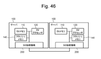
- the configuration of the server-server connection is shown.
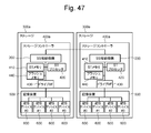
- the configuration of storage-storage connection is shown.
- aaa table such as “aaa list”, “aaaDB”, “aaa queue”, etc.
- the information is a data structure such as a table, list, DB, queue, etc. It may be expressed in other than. Therefore, “aaa table”, “aaa list”, “aaaDB”, “aaa queue”, etc. may be referred to as “aaa information” to indicate that the information does not depend on the data structure.
- program is used as the subject.
- the program performs processing determined by being executed by the processor using the memory and communication port (communication control device)
- the processor is used as the subject.
- the explanation may be as follows. Further, the processing disclosed with the program as the subject may be processing performed by a computer such as a storage controller or an information processing apparatus. Further, part or all of the program may be realized by dedicated hardware.
- various programs may be installed in each computer by a program distribution server or a computer-readable memory media.
- the program distribution server includes a processor (for example, CPU: Central Processing Unit) and a storage resource, and the storage resource further stores a distribution program and a program to be distributed.
- the distribution program is executed by the CPU, the CPU of the program distribution server distributes the distribution target program to other computers.
- SS server storage
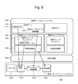
- FIG. 1 shows the configuration of the server storage system of the embodiment.
- This SS system includes a server 100 and a storage system 300.
- the server 100 and the storage system 300 may be stored in one housing.
- the SS system is sometimes called a computer system.
- the server 100 includes a server (SV) memory 110, a server (SV) processor 120, and a server storage (SS) connection mechanism 200.
- the SV memory 110 and the SV processor 120 are connected to each other via an internal bus.
- the SV memory 110 is a memory, and stores a program and data for controlling the server 100 such as an application, an OS (Operating System), and a driver.
- the SV processor 120 is a microprocessor and executes processing according to a program in the SV memory 110.
- the SS connection mechanism 200 is connected to the SV processor 120 via the server-side bus and is connected to the storage system 300 via the storage-side bus, and controls communication between the SV processor 120 and the storage system 300.
- the SV processor 120 and the SS connection mechanism 200 are connected by a server-side bus.
- the SS connection mechanism 200 and the ST processor 420 are connected by a storage-side bus that is the same type of bus as the server-side bus.
- PCI Express PCI Express
- Each of the server side bus and the storage side bus may be a substrate such as a backplane or a cable.
- DMA transfer between the storage areas of the server 100 and the storage system 300 can be performed by connecting the server 100 to the storage system 300 through the same bus as the internal bus of the server 100, and the request issued from the SV processor 120
- the storage (ST) processor in the storage system 300 activates the DMA engine installed in the SS connection mechanism 200, and the data on the ST memory in the storage system 300 is transferred to the SV memory 110 or the SV memory 110.
- ST memory are transferred to the ST memory in the storage system 300.
- the server 100 may include an FM with a compression / decompression function, which is a flash memory (FM) having a compression / decompression function.
- the server 100 may include a Root Complex (RC) connected to the SV processor 120 via an internal bus and connected to the SS connection mechanism 200 via a server-side bus.
- RC Root Complex
- the SS connection mechanism 200 compresses the write data from the server 100 and transfers it to the storage system 300, decompresses the read data from the storage system 300 and transfers it to the server 100.
- the storage system 300 includes a storage (ST) controller 400 and a storage device 500.
- the storage device 500 stores data accessed from the server 100.
- the ST controller 400 is connected to the storage device 500 and the server 100 and controls access to the storage device 500.
- the ST controller 400 may be referred to as a controller.
- the ST controller 400 includes a storage (ST) memory 410, a storage (ST) processor 420, and a drive interface (I / F) 430.
- the ST memory 410, the ST processor 420, and the drive I / F 430 are connected to each other via an internal bus.
- the ST memory 410 is a memory and stores a program and data for controlling the storage system 300.
- the ST processor 420 is a microprocessor, is connected to the SS connection mechanism 200 via a storage-side bus, and executes processing according to a program stored in the ST memory 410.
- the drive I / F 430 is connected to the storage device 500 via the storage device side bus and controls communication between the ST processor 420 and the storage device 500.
- the ST controller 400 may include an FM with a compression / decompression function.
- the ST processor 420 can compress and expand the cached data using the FM with compression / decompression function as a cache area.
- the ST controller 400 may include an RC connected to the ST processor 420 via an internal bus and connected to the SS connection mechanism 200 via a storage-side bus.
- the storage device 500 includes a plurality of storage devices 600 (# 0, # 1, # 2, # 3).
- the physical storage device 600 may be called a physical device, and the virtual storage device may be called a virtual device.
- a physical device including the data compression / decompression function may be referred to as a compressed storage device 600a, and a physical device not including the data compression / decompression function may be referred to as an uncompressed storage device 600b.
- compression and decoding of data may be performed by the compression storage device 600a, the ST controller 400, or the server 100.
- compression in the SS system can be replaced with other transformations such as deduplication.
- conversion result data is generated from the original data.
- the size of the conversion result data is smaller than the size of the original data.
- original data is generated from the conversion result data by inverse conversion.
- the inverse transform for compression is decompression.
- the inverse transformation for deduplication is the restoration of the original data.
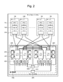
- FIG. 2 shows the configuration of the server storage system of the first specific example.
- Each SS connection mechanism 200 may be directly connected to a plurality of ST controllers 400.
- the SS system of the first specific example includes a plurality of servers 100 and one storage system 300.
- the storage system 300 includes two ST controllers 400.
- Each ST controller 400 includes two ST processors 420, a plurality of ST memories 410 connected to each ST processor 420, and a plurality of drive I / Fs 430 connected to each ST processor 420.
- the two ST processors 420 in one ST controller 400 are respectively connected to the two ST processors 420 in the other ST controller 400 via the inter-ST controller 400 bus.
- a plurality of ST processors 420 may be provided. In the case of a plurality of ST controllers, each ST processor 420 in the other ST controller 400 is connected to each other via an inter-ST controller bus.
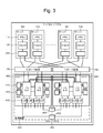
- FIG. 3 shows the configuration of the server storage system of the second specific example.
- Each SS connection mechanism 200 may be connected to a plurality of ST controllers 400 via the interface expansion device 700.
- the SS system of the second specific example includes a plurality of servers 100 and an interface expansion device 700 connected to each ST controller 400.
- the interface expansion device 700 performs control to increase the number of connection paths between the server 100 and the ST controller 400. With the interface expansion device 700, more servers 100 can be directly connected to one storage.
- the interface expansion device 700 is, for example, a PCIe switch.
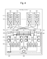
- FIG. 4 shows the configuration of the server storage system of the third specific example.
- Each server 100 may include a plurality of SS connection mechanisms 200.
- each server 100 includes two SS connection mechanisms 200.
- the two SS connection mechanisms 200 are connected to the two ST controllers 400 via the interface expansion device 700, respectively.
- the storage side bus and the server side bus can be balanced by setting the storage side bus to two PCIex4 and the server side bus to one PCIex8.
- the storage side bus by changing the storage side bus to one PCIex4 and the server side bus to one PCIex8, only the bandwidth of the storage side bus is changed to 1 ⁇ 2.
- the compressed data transferred from the storage-side bus to the SS connection mechanism 200 is decompressed by the SS connection mechanism 200 and transferred to the server-side bus
- the data that has been compressed to 1 ⁇ 2 in the storage-side bus is Even if the server-side bus returns to the original size data, the storage-side bus and the server-side bus can secure their respective bandwidths.
- each server 100 includes two SS connection mechanisms 200, thereby ensuring hardware redundancy.
- Each server 100 may include one SS connection mechanism 200, and the bandwidth of the server side bus may be set wider than that of the storage side bus in consideration of the compression rate.
- the storage side bus may be two PCIex4, and the server side bus may be one PCIex16.
- the same effect can be obtained even if the storage side bus is two PCIex4 and the server side bus is two PCIex8. In this way, the server-side bus and the storage-side bus can be assigned the necessary bandwidth according to the compression, according to PCIe.
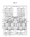
- FIG. 5 shows the configuration of the server storage system of the fourth specific example.
- the SS system may include a plurality of storage systems 300.
- the SS system includes two storage systems 300.
- the two SS connection mechanisms 200 in one server 100 are connected to the two storage systems 300 via the interface expansion device 700, respectively.
- One SS connection mechanism 200 is connected to two ST controllers 400 in one storage system 300 via the interface expansion device 700.
- this configuration by installing two SS connection mechanisms 200 in the server 100, more storage systems 300 can be connected to the server 100, and broadband and high-performance storage resources can be provided to the server 100. .
- FIG. 6 shows the configuration of the virtual server storage system.
- the physical SS system 2000 may execute the virtualization mechanism 3000 and execute the virtual server storage (SS) system 1000 on the virtualization mechanism 3000.
- the virtual SS system 1000 includes a virtual server 1100 and a virtual storage system 1300.
- the SS system 2000 physically includes at least a processor 2020, a memory 2010, a storage device 2500, and an SS connection mechanism 2200.
- the virtual server 1100 provides the same function as the server 100. More specifically, the virtual server 1100 includes a virtual SV memory 2110 that provides the same function as the SV memory 110 and a virtual SS connection mechanism 1200 that provides the same function as the SS connection mechanism 200.
- the virtual storage system 1300 includes a virtual ST controller 1400 that provides the same functions as the ST controller 400 and a virtual storage device 1500 that provides the same functions as the storage device 500.
- the virtual ST controller 1400 includes a virtual ST memory 1410 that provides the same functions as the ST memory 410.
- the virtualization mechanism 3000 assigns the storage area in the memory 2010 to the virtual SV memory 1110, assigns the processing capacity of the SS connection mechanism 2200 to the virtual SS connection mechanism 1200, assigns the storage area in the memory 2010 to the virtual ST memory 1410, A storage area in the storage device 2500 is allocated to the virtual storage device 1500.
- the virtual SS system 1000 may be executed on a computer system having another configuration such as a single server or a server and storage system.
- the computer system may include a compression / decompression circuit instead of the SS connection mechanism.
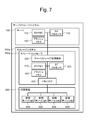
- FIG. 7 shows a configuration of a modified server storage system.
- the SS system includes a storage system 300a instead of the storage system 300, and includes an ST controller 400a instead of the ST controller 400.
- the SS connection mechanism 200 is provided in the ST controller 400a.
- the SS connection mechanism 200 is connected to the SV processor 120 in the server 100 and is connected to the ST processor 420 in the ST controller 400a.
- the server 100 may further include an FM 140.
- the FM 140 may have a compression / decompression function, and may perform compression / decompression in accordance with an instruction from the SV processor 120.
- the ST controller 400a may further include an FM 440.
- the FM 440 may have a compression / decompression function, and may perform compression or expansion instead of the SS connection mechanism 200 in response to an instruction from the ST processor 420.
- the write operation is performed by the FM 140 before the data is sent to the SS connection mechanism 200 in the flow disclosed in FIGS.
- the SS connection mechanism 200 reads out and decompresses this compressed data, and further writes it into the storage device 600 via the ST memory 410 while recompressing it into the compression format of the storage system 300 of this embodiment.
- the SS connection mechanism 200 may further compress the compressed data into the compression format of the storage system 300 of this embodiment without expanding the compressed data when it is read. With this configuration, the write band can be widened.
- the read operation is performed when the SS connection mechanism 200 reads the data compressed by the FM 440 in the ST controller 400a or the data compressed and stored in the storage device 600 in the flow disclosed in FIGS.
- the DMA transfer is performed with the FM 140 or the SV memory 110 on the server 100 side while recompressing the compressed format of the server 100 above.
- the SS connection mechanism 200 realizes a broadband system in cooperation with the FM 440 having a compression / decompression function.
- the SS connection mechanism 200 may be provided in the server 100, may be provided in the ST controller 400, or may be provided between the server 100 and the ST controller 400.
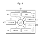
- FIG. 8 shows the configuration of the SS connection mechanism 200.
- the SS connection mechanism 200 is implemented as, for example, an ASIC (application specific integrated circuit).
- the SS connection mechanism 200 includes an IF (Interface) processor 210, a DMA (Direct Memory Access) controller 220, an internal memory 230, a register 240, an interface 250, two interfaces 260, and an internal switch 270.
- the DMA controller 220 may be called DMA.
- the IF processor 210, the DMA controller 220, the internal memory 230, the register 240, the interface 250, and the two interfaces 260 are connected to each other via an internal switch 270.
- One interface 250 is connected to the SV processor 120 via a server-side bus.
- the other two interfaces 260 are connected to the two ST processors 420 via storage-side buses, respectively.
- the internal memory 230 is a memory and stores programs and data.
- the IF processor 210 is a microprocessor and executes processing according to a program in the internal memory 230.
- the DMA controller 220 executes data transfer (transfer between memories) according to an instruction from the IF processor 210.
- the register 240 stores a setting value of the IF processor 210.
- the internal switch 270 controls communication between the units in accordance with instructions from the IF processor 210. Note that there may be a plurality of SV side interfaces and ST side interfaces, and they may be connected to the SV processor 120 and the ST processor 420 via each bus and interface expansion.
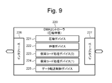
- FIG. 9 shows the configuration of the DMA controller 220.
- the DMA controller 220 includes a compression device 221, an expansion device 222, a guarantee code processing device (0) 224, a guarantee code processing device (1) 224, a data transfer control device 225, and two interfaces 226 and 227. Including. The two interfaces are connected to an internal switch.
- the compression device 221 compresses uncompressed data and converts it into compressed data.
- the decompression device 222 decompresses the compressed data and converts it into uncompressed data.
- the guarantee code processing device (0) 223 calculates a guarantee code for uncompressed data, and adds a guarantee code to the uncompressed data. Further, the guarantee code processing device (0) 223 detects an error in the non-compressed data based on the non-compressed data and the guarantee code.
- the guarantee code processing device (1) calculates a guarantee code for the compressed data and adds the guarantee code to the compressed data. Furthermore, the guarantee code processing device (1) 224 detects an error in the compressed data based on the compressed data and the guarantee code. Each security code processing device also deletes the security code.
- the data transfer control device 225 controls data transfer.
- DMA transfer can be performed between the SV memory 110 in the server 100 and the ST memory 410 of the ST controller 400.
- Data compression or decompression can be performed.
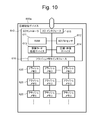
- FIG. 10 shows the configuration of the compressed storage device 600a.
- the compressed storage device 600 a includes a storage device (SD) controller 610 and a plurality of flash memories (FM) 620 connected to the SD controller 610.
- the SD controller 610 includes a RAM (Random Access Memory) 611, a physical device (SD) processor 612, a guarantee code processing device 613, a compression / decompression device 614, an I / O interface 615, and an FM interface 616.
- Each unit in the SD controller 610 is connected to each other via an internal bus.
- the I / O interface 615 is connected to the drive I / F 430 of the ST controller 400 via the storage device side bus.
- the RAM 611 is a DRAM (Dynamic RAM), for example, and stores programs and data.
- the SD processor 612 is a microprocessor and executes processing according to a program stored in the RAM 611.
- the security code processing device 613 generates a security code based on the data, adds a security code to the data, checks the data based on the data and the security code, and detects an error. The security code is also deleted.
- the compression / decompression device 614 compresses the uncompressed data and converts it into compressed data, and decompresses the compressed data and converts it into uncompressed data.
- the FM interface 616 is connected to a plurality of FMs 620.
- the compressed storage device 600a may perform compression or expansion in place of the SS connection mechanism 200 in response to an instruction from the ST processor 420. Further, the compression storage device 600a may compress the data by internal determination with respect to the data input, and may decompress and output the internally compressed data unless there is a specific instruction from the ST processor 420. .
- FIG. 11 shows the configuration of the storage area in the ST memory 410.
- the storage area in the ST memory 410 includes a virtual volume management table 810, a storage pool management table 820, a RAID group management table 830, a physical device management table 840, a virtual page management table 850, and a real page management table 860. And a free real page management table 870. These tables will be described later.
- the storage area in the ST memory 410 further includes a storage (ST) cache area 880 and a storage (ST) buffer area 890.
- the ST cache area 880 temporarily holds write data and read data, and is used for data hits for write and read access.
- the ST buffer area 890 stores data and control information transmitted / received by the ST controller 400.
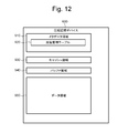
- FIG. 12 shows the configuration of the storage area in the compressed storage device 600a.
- the storage area in the compressed storage device 600a includes a metadata area 910, a cache area 930, a buffer area 940, and a data area 950 in the FM 620 in the RAM.
- the metadata area 910 stores metadata and includes a compression management table 920.
- the cache area 930 stores temporary data.
- the buffer area 940 stores data and control information transmitted / received by the compressed storage device 600a.
- the data area 950 stores data. Note that the information in the RAM 611 in the SD controller 610 may be in the connected FM 620.
- FIG. 13 shows the configuration of the storage area in the storage system 300.
- the ST controller 400 allocates a storage area in the physical device to the virtual device.
- the physical device may be either a compressed storage device 600a (compressed SD) or an uncompressed storage device (uncompressed SD).
- the ST controller 400 creates a parity group using a plurality of virtual devices.
- the parity group may be either a compressed parity group using a plurality of virtual devices based on a plurality of compressed storage devices 600a or an uncompressed parity group using a plurality of virtual devices respectively based on a plurality of uncompressed storage devices. good.
- the ST controller 400 uses the storage pool management table 820 to allocate storage areas in the parity group to the storage pool.
- the ST controller 400 uses the virtual volume management table 810 to allocate a storage area in the storage pool to the virtual volume.
- each storage pool there may be a compressed storage pool for storing compressed data and an uncompressed storage pool for data stored without being compressed.
- the compressed storage pool may be provided by, for example, a compressed parity group including a storage area of a functional device having a compression function, and storage in the pool is connected to the ST controller 400 or the ST controller 400. It may be configured to be compressed by a compression mechanism.
- the virtual volume can also be a compressed virtual volume in which written data is compressed and stored in the storage area, and an uncompressed virtual volume in which the written data is stored in the storage area without being compressed. You may do it.
- the ST controller 400 provides the virtual volume to the server 100.
- FIG. 14 shows the configuration of pages in the storage system 300.
- Parity group includes multiple real pages.
- the virtual volume includes a plurality of virtual pages.
- the ST controller 400 uses the real page management table 860 to assign real pages to virtual pages.
- the total size of real pages allocated to virtual pages can be made larger than the total size of physical devices.
- the ST controller 400 can switch between a real page in the compressed parity group and a real page in the non-compressed parity group and assign it to the virtual page. Thereby, the presence or absence of the compression effect can be switched.
- the total size of real pages allocated to virtual pages is set to the same size as the total size of physical devices, the utilization rate is reduced without increasing the capacity of the FM 620, and the life of the FM 620 is extended. You can also.
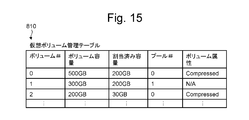
- FIG. 15 shows the virtual volume management table 810.
- the virtual volume management table 810 includes an entry for each virtual volume.
- An entry corresponding to one virtual volume includes a volume number (#), a volume capacity, an allocated capacity, a pool number (#), and a volume attribute.
- the volume number is an identifier indicating the virtual volume.
- the volume capacity is the capacity of the virtual volume.
- the allocated capacity is the total size of virtual pages to which real pages are allocated in the virtual volume.
- the pool number is an identifier indicating a storage pool including a real page that can be allocated to the virtual volume.
- the volume attribute indicates the presence or absence of compression in the virtual volume.
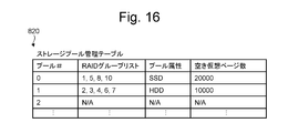
- FIG. 16 shows the storage pool management table 820.
- the storage pool management table 820 includes an entry for each storage pool.
- the entry corresponding to one storage pool includes a pool number (#), a RAID (Redundant Arrays of Inexpensive Disks) group list, a pool attribute, and the number of free virtual pages.
- the pool number is an identifier indicating the storage pool.
- the RAID group list is an identifier indicating a RAID group included in the storage pool.
- the pool attribute indicates the type of physical device used for the storage pool.
- the number of free virtual pages indicates the number of free virtual pages in the storage pool.
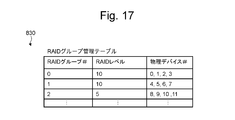
- FIG. 17 shows the RAID group management table 830.
- the RAID group management table 830 includes an entry for each RAID group.
- An entry corresponding to one RAID group includes a RAID group number (#), a RAID level, and a physical device number (#).
- the RAID group number is an identifier indicating the RAID group.
- the RAID level indicates the RAID level of the RAID group.
- the physical device number is an identifier indicating a physical device used for the RAID group.
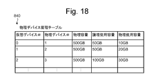
- FIG. 18 shows the physical device management table 840.
- the physical device management table 840 includes an entry for each physical device.
- the entry corresponding to one physical device includes a virtual device number (#), a physical device number (#), a physical capacity, a logical usage capacity, and a physical usage capacity.
- the virtual device number is an identifier indicating a virtual device to which the physical device is assigned.
- the physical device number is an identifier indicating the physical device.
- the physical capacity is the capacity of the physical device.
- the logical usage capacity is the usage amount of the logical storage area of the virtual device.
- the physical usage capacity is the usage amount of the physical storage capacity of the physical device.
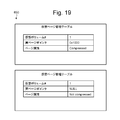
- FIG. 19 shows a virtual page management table 850.
- the virtual page management table 850 is created for each virtual page.
- the virtual page management table 850 corresponding to one virtual page includes a virtual volume number (#), a real page pointer, and a page attribute.
- the virtual volume number is an identifier indicating a virtual volume including the virtual page.
- the real page pointer is a pointer that points to a real page assigned to the virtual page.
- the page attribute indicates whether the actual page stores compressed data or non-compressed data.
- the upper virtual page management table 850 indicates a virtual page to which a real page is allocated, and a real page pointer points to the real page.
- the lower virtual page management table 850 indicates a virtual page to which no real page is allocated, and the real page pointer indicates NULL.
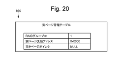
- FIG. 20 shows the real page management table 860.
- the real page management table 860 is created for each real page.
- the real page management table 860 corresponding to one real page includes a RAID group number (#), a real page head address, and a free page pointer.
- the RAID group number is an identifier indicating a RAID group including the real page.
- the real page head address indicates the head address of the real page in the RAID group.
- the free page pointer points to the real page management table 860 of the next free real page when the real page is a free real page.
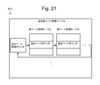
- FIG. 21 shows a free real page management table 870.
- the free real page management table 870 includes a free page management pointer. This empty page management pointer points to the actual page management table 860 for empty pages. The empty page pointer in the real page management table 860 of the last empty page of consecutive empty pages indicates the empty page management pointer.
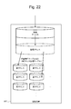
- FIG. 22 shows the configuration of the storage area in the physical device.
- the compression storage device 600a stores the compression management table 920 in the RAM 611 or the FM 620.
- the SD controller 610 of the compressed storage device 600a provides the ST controller 400 with a logical address in units of blocks in the storage area, and assigns real addresses in units of blocks to the logical addresses using the compression management table 920.
- the block unit shown here indicates a data unit of block storage.
- the compression storage device 600a determines whether or not compression is possible in a unit in which a plurality of blocks are grouped in terms of non-compressed data (for example, 8 kB in which a plurality of block sizes of 0.5 kB are grouped, hereinafter compression unit). Compress uncompressed data for each compression unit.
- the uncompressed storage device stores the real address management table in the RAM.
- the SD controller 610 of the uncompressed storage device provides a logical address for each block to the ST controller 400, and assigns a real address of the block to the logical address using the real address management table.
- FIG. 23 shows the compression management table 920.
- the compression management table 920 is stored in the RAM 611 or FM 620 in the storage device 600 for each storage device 600.
- the compression management table 920 is stored in the HDD.
- the compression management tables 920 of a plurality of storage devices 600 may be collected and stored in the ST memory 410 of the storage controller or the flash memory of the storage controller for management.
- the compression management table 920 includes an entry for each compression unit in the compression storage device 600a.
- An entry corresponding to one compression unit includes a logical address, a real address, a compression flag, and the number of blocks after compression.
- the logical address indicates the first logical address of the compressed data.
- the real address indicates the first real address of the compression unit.
- the compression flag indicates whether data in the compression unit is compressed.
- the number of blocks after compression indicates the number of blocks for the compressed data of the uncompressed data. Here, when all the blocks in the compression unit are non-compressed data, the number of blocks after compression is the maximum block number. When the compression unit includes a compression block, the number of compression blocks is smaller than the maximum block number.
- FIG. 23 shows a case where the 8 KB compression unit is 8 KB compressed data. At this time, it is determined by the compression flag whether the corresponding 8 KB is compressed data.
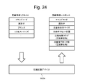
- FIG. 24 shows a first operation in which the ST controller 400 acquires compressed information from the compressed storage device 600a.
- Compression information is information related to compression of target data stored in the compression storage device 600a.
- the ST controller 400 issues a compression information request for acquiring the compression information of the target data to the compression storage device 600a.
- the compression storage device 600a reads the compression information of the target data from the compression management table 920 in response to the compression information request, and issues a compression information response indicating the compression information to the ST controller 400.
- the compression information indicates the compression state of the target data.
- the compression information request includes a command code indicating that the compression information is requested, an identifier of the request, an address that is a logical address of the target data in the compression storage device 600a, and a request size that is the size of the target data. Including.
- the compressed information response is obtained by decompressing the corresponding compressed information request identifier, the compressed overall size of the compressed unit group including the target data, and the first compressed unit of the compressed unit group including the target data.
- the first offset position which is an offset from the beginning of the decompressed data to the beginning of the target data.
- the compression information response includes, for each compression unit in the compression unit group, a compression presence / absence flag indicating the presence / absence of compression of the compression unit, and a post-compression block number indicating the number of blocks in the compression unit after compression. .
- the ST controller 400 determines that the number of blocks after compression is the same as the number of blocks before compression, the ST controller 400 determines non-compression, and when the number of blocks after compression differs from the number of blocks before compression, the compression presence / absence flag is unnecessary It is also good.
- the ST controller 400 can acquire compression information of data compressed by other than the ST controller 400, such as the compression storage device 600a and the SS connection mechanism 200.
- the ST controller 400 can obtain the compression information necessary for decompression by sending the compression information to other parts in the SS system even if the part is a part other than the part where the compression is performed.
- the ST controller 400 reads the compressed data distributed and stored in the plurality of compressed storage devices 600a in the order of logical addresses, and acquires the compression information from the respective compressed storage devices 600a, whereby a plurality of compressed storages are obtained.
- the compressed data stored in the device 600a can be rearranged so as to be continuously stored in the ST memory 410.
- the ST controller 400 uses SGL for rearrangement and is logically continuous, and may not be physically continuous.
- the SS connection mechanism 200 can sequentially read the compressed data from the ST memory 410.
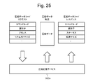
- FIG. 25 shows an operation in which the ST controller 400 acquires compressed data from the compressed storage device 600a.
- the compressed storage device 600a compresses and stores the data received from the ST controller 400
- the compressed storage device 600a generates uncompressed data by expanding the compressed data in response to a normal read request, and sends the uncompressed data to the ST controller 400. Can be sent.
- the ST controller 400 issues a compressed data read request to the compressed storage device 600a in order to acquire target data stored in the compressed storage device 600a as compressed data.
- the compressed storage device 600a reads the compressed data in response to the compressed data read request, transmits the compressed data of the target data, and issues a compressed data read response indicating the read result to the ST controller 400.
- the compressed data read request is a command code for instructing to read compressed data as it is compressed, an identifier of the request, an address that is a logical address of the target data in the compressed storage device 600a, and a size of the target data. Including request size. Note that the value acquired by the above-described compression information read is used as the size of the target data.
- the compressed data read response includes an identifier of the corresponding compressed data read request, a status related to the read processing, and a transfer size indicating the size of the target data transferred to the ST controller 400.
- the ST controller 400 can acquire the compressed data of the target data without decompressing it with the compressed storage device 600a. Thereby, the bandwidth of the bus between the compressed storage device 600a and the ST controller 400 and the amount of bandwidth used in the ST controller 400 can be reduced.
- the compression information is acquired by using the second operation shown in FIG. 26 as a method for the ST controller 400 to acquire the compression information and the compressed data with a single request.
- the compressed data is read at the beginning or end of the compressed data when sent, or the compressed data read response is added as in the third operation shown in FIG. It is also good.
- only the compressed data read is performed without performing the compression information read, and the data size before compression is set as the target data size of the compressed data read request.
- the data size after compression is set as the size of the target data of the compressed read response corresponding to this request.
- the ST controller 400 When receiving the compressed read response, the ST controller 400 acquires the compressed data size from the compressed information read together with the compressed data, and compares it with the transferred size of the compressed read response. Even when a transfer size underflow error occurs, it is determined that the transferred data has been transferred by the data size after compression, and the transfer is determined to be normal. After this, expanded DMA transfer is carried out, and the final transfer data consistency is determined by checking the security code in the DMA transfer.
- the compressed read response can be implemented with an auto response. It also reduces performance overhead due to an increase in the number of requests by combining compressed information acquisition and compressed data acquisition requests at once.
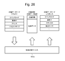
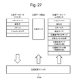
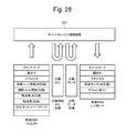
- FIG. 28 shows an operation between the ST controller 400 and the SS connection mechanism 200 in the decompression DMA process.
- the ST controller 400 can issue a decompression DMA request for instructing decompression DMA processing to the SS connection mechanism 200.
- the decompression DMA process is a process of reading the compressed data of the target data from the designated memory, decompressing the compressed data to generate uncompressed data, and writing the uncompressed data to the designated memory.
- the decompression DMA processing reads the compressed data of the target data from the ST memory 410 in the ST controller 400, decompresses the compressed data to generate uncompressed data, and sends the uncompressed data to the SV memory 110 in the server 100. Write.
- the SS connection mechanism 200 reads compressed information SGL which is SGL (Scatter / Gather List) indicating information related to compressed data in the ST memory 410 based on the decompressed DMA request. Further, the SS connection mechanism 200 reads the compressed data from the storage area indicated by the compression information SGL in the ST memory 410. Further, the SS connection mechanism 200 decompresses the compressed data, writes the uncompressed data to the SV memory 110, and then issues a decompressed DMA response to the ST controller 400.
- the compression information SGL is a list that sequentially indicates the addresses and sizes of the plurality of compressed data in the ST memory 410 when a plurality of compressed data stored in a distributed manner in the storage system 300 is read to the ST memory 410. It is.
- the compressed data when compressed data is stored in a RAID group, the compressed data is distributed and stored in the ST memory 410.
- the SS connection mechanism 200 can read the compressed data sequentially by following the compression information SGL, and can sequentially decompress and write the compressed data to the SV memory 110. As a result, the performance can be improved as compared with the case where each unit stored in a distributed manner is expanded and transferred.
- the decompression DMA request is added to a command code indicating decompression DMA processing, an identifier indicating a read request from the server 100 that is the basis of the decompression DMA request, parameters such as compression of the target data, and uncompressed data of the target data.
- Uncompressed security code information indicating the security code compressed security code information indicating the security code added to the compressed data of the target data, uncompressed transfer length indicating the length of the uncompressed data of the target data, and target data
- the uncompressed transfer length indicating the length of the uncompressed data and the SGL address that is the address of the compressed information SGL in the ST memory 410 is included.
- the data address may be directly specified instead of the SGL address, or both the data address and the SGL address may be set. When only the data address is set, acquisition of the compression information SGL is omitted.
- the guarantee code is an expected value of a value calculated by a guarantee code calculation such as CRC (Cyclic Redundancy Check) from the read data and the address where the data is stored.
- CRC Cyclic Redundancy Check
- the ST controller 400 includes the security code information necessary for checking the security code in the expanded DMA request or the like and transmits it to the SS connection mechanism 200. Since the address managed by the ST controller 400 may be different from the address designated by the server 100, it is included in the guarantee code information and transmitted from the ST controller 400 to the SS connection mechanism 200. For example, when the ST controller 400 performs thin provisioning, the address in the storage pool is included in the guarantee code information.
- the SS connection mechanism 200 can check whether or not there is an error in the compressed data and the non-compressed data and whether or not the compressed data is read from the designated address. Also, when a guarantee code is added to the compressed data, the ST processor 420 decompresses the expected value to the SS connection mechanism 200 by considering offloading the processing to hardware and reducing the load on the ST processor 420. Pass in request.
- the SS connection mechanism 200 removes the storage device dedicated code from the compressed data based on the information indicating the position of the storage device dedicated code.
- Information indicating the location of the storage device dedicated code may be included in a parameter in the decompression DMA request, or may be stored in advance in a register in the SS connection mechanism 200.
- the SS connection mechanism 200 removes the storage device dedicated code from the compressed data read from the compressed storage device 600a and decompresses it. can do. Note that there is a possibility that the storage device dedicated code is included in both the compressed data and the decompressed data, and when added to both, the SS connection mechanism 200 removes both.
- the decompression DMA response includes a command code indicating that it is a decompression DMA response, a corresponding decompression DMA request identifier, a status relating to decompression DMA processing, and an uncompressed transfer size indicating the size of uncompressed data transferred to the server 100. And an error report indicating an error in the decompression DMA processing.
- the ST controller 400 can know the non-compressed data of the target data.
- the ST controller 400 can issue a compressed DMA request that instructs the compressed DMA processing to the SS connection mechanism 200.
- the compressed DMA process is a process of reading uncompressed data of target data from a specified memory, compressing the uncompressed data to generate compressed data, and writing the compressed data to the specified memory.
- uncompressed data of the target data is read from the SV memory 110 in the server 100, the uncompressed data is compressed to generate compressed data, and the compressed data is sent to the ST memory 410 in the ST controller 400.
- Write is a process of reading uncompressed data of target data from a specified memory, compressing the uncompressed data to generate compressed data, and writing the compressed data to the specified memory.
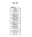
- FIG. 29 shows the compression information SGL.
- the ST processor 420 When the ST processor 420 secures a storage area for storing the target data in the ST memory 410, the ST processor 420 generates compressed information SGL indicating the storage area and stores it in the ST memory 410.
- the area for storing data in the ST memory 410 may be divided into a plurality of locations, and the compressed information SGL may have information for each of the plurality of addresses.
- the compression information SGL includes an identifier of the compression information SGL and information related to the compression information SGL, how many valid addresses are present in the compression information SGL, whether there is no next SGL, and is a terminal SGL. SGL information indicating that the next SGL address is valid is included.
- the compression information SGL further includes transfer data information (i) for each transfer data (i) in the target data (i is 0, 1,).
- the transfer data information (i) includes an address (i) of the compression information (i) in the ST memory 410 and a transfer size (i) indicating the compressed data size of the transfer data (i) corresponding to the address (i).
- the compression information SGL includes a next SGL address that is an address of the next compression information SGL when the next compression information SGL is set to be continuous in the SGL information described above.
- the compression information SGL includes an SGL field check code for checking each field in the compression information SGL. If there is compression for each compression unit and compression is not possible, the same number of blocks as the compression unit is stored. If compression is possible, the number of blocks smaller than the compression unit is stored and the compression presence flag is set.
- the transfer size may be omitted as it is calculated from the number of blocks after compression.
- the compression information SGL shown here is only an example, and other compression-related information such as the head offset position acquired by acquiring the compression information described above may be mounted.
- the SS connection mechanism 200 performs the compression. By tracing the information SGL, the target data can be read sequentially from the ST memory 410.
- the decompressed DMA request may include the contents of the compressed information SGL instead of the SGL address.
- the size of the decompressed DMA request may be enlarged or concatenated so that a large amount of information is loaded, and the content of the compressed information SGL may be placed in the decompressed DMA request without using the SGL.
- the compressed information may be mounted separately for both the decompressed DMA request and the SGL.
- the SV processor 120 when the SV processor 120 secures a storage area for storing the target data in the SV memory 110, the SV processor 120 generates a server SGL that is an SGL indicating the storage area, and stores the server SGL in the SV memory 110.
- the server SGL includes SGL information including an identifier of the server SGL, the number of valid addresses in the SGL, a flag indicating whether there is a next SGL, a flag indicating whether the SGL is a termination, and the server 100.
- Side storage destination address and transfer size A plurality of storage destination addresses and transfer sizes may be stored in the same manner as the compression information SGL. Further, a check code for the next SGL address or SGL field may be included. Further, information regarding other transfer destinations may be included.
- the SS connection mechanism 200 traces the server SGL, so that the SV memory 110 The target data can be read sequentially from
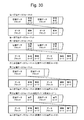
- FIG. 30 shows the data format
- the compressed data is stored in this format in the compressed storage device 600a.
- the compressed data is read from the compressed storage device 600a to the ST controller 400 in this format, and is read from the ST controller 400 to the SS connection mechanism 200.
- the SS connection mechanism 200 generates uncompressed data by decompressing the compressed data.
- the compressed data format includes a first compressed data format, a second compressed data format, and a third compressed data format
- the non-compressed data format includes a first uncompressed data format and a second uncompressed data format.
- the combination of the compressed data format and the non-compressed data format may be a combination other than the notation correspondence.
- the format shown here is an example, and other formats may be used as long as the correspondence between the compressed data format and the non-compressed data format is defined.
- the compressed data includes a plurality of compressed data blocks.
- the compressed data block is a compression unit. After each compressed data block, a security code for the compressed data block is added. When the compressed data block is expanded, it becomes a plurality of data blocks.
- a data block is a block. Each data block is followed by a security code for that data block.
- the storage device 600a When the compressed storage device 600a compresses and stores the data from the ST controller 400, the compressed data is distributed and written to a plurality of FMs 620. Therefore, the storage device indicates the CRC and the address in the FM 620 unique to the compressed storage device 600a.
- a dedicated code may be added. In this case, the second uncompressed data format is used. In the second non-compressed data format, a guarantee code of the data block is added after each data block, and a storage device dedicated code (dedicated code) is added after the guarantee code.
- the dedicated code shown here is a unique code added for exclusive use by the storage device 600 itself, and corresponds to, for example, a security code generated and added by the storage device 600.
- the storage device dedicated code is removed from the uncompressed data and transferred to the server 100. Further, as in the third non-compressed data format and the third non-compressed data format, the storage device dedicated code may be added to the compressed data. In this case as well, the SS connection mechanism 200 similarly uses the compressed data. Before decompressing, the storage device dedicated code is removed and the decompression process is performed.
- the server 100 reads the target data using the compressed data in the compressed storage device 600a as the target data
- the SS connection mechanism performs the decompression process in the DMA process, thereby enabling the data decompression process to be consistent with the direct data transfer process between the memories between the server storages.
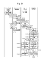
- FIG. 31 shows a first process in the SS system read process
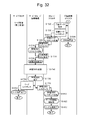
- FIG. 32 shows a second process following the first process in the SS system read process.
- These drawings show operations of the SV processor 120 in the server 100, the IF processor 210 in the SS connection mechanism 200, the ST processor 420 in the ST controller 400, and the SD processor 612 in the compressed storage device 600a.
- a read process when the target data expansion process is performed by the SS connection mechanism 200 will be described.
- the SV processor 120 in the server 100 prepares the SV memory 110 area for the read size in the SV memory 110 as a storage area for storing the read data.
- the SV processor 120 generates a server SGL, which is an SGL indicating the SV area, and stores it in the SV memory 110.
- the SV processor 120 generates a read request and issues it to the SS connection mechanism 200.
- the read request indicates a virtual volume indicating a storage area in which target data is stored and a virtual page in the virtual volume.
- the IF processor 210 in the SS connection mechanism 200 performs a read request process for analyzing a read request queued from the SV processor 120.
- IF processor 210 generates a read request based on the analysis result and issues it to ST controller 400.
- a read request from the IF processor 210 to the ST controller 400 may be referred to as a read command in order to distinguish from a read request from the SV processor 120 to the IF processor 210.
- the issue destination is the ST controller 400 and ST processor having ownership of the storage area for storing the specified target data.
- the IF processor 210 performs server SGL processing for acquiring the server SGL.
- the IF processor 210 receives the server SGL from the server 100.
- the IF processor 210 stores the received server SGL in the internal memory. Note that address information and length information to be mounted on the SGL may be included in the read request, and if the read request cannot be completed, the remaining information may be in the form of the SGL.
- the ST processor 420 in the ST controller 400 performs a read request process for analyzing the read request queued from the IF processor 210.
- the ST processor 420 executes a read request based on the virtual volume management table 810, the storage pool management table 820, the RAID group management table 830, the physical device management table 840, the virtual page management table 850, and the real page management table 860.
- the compressed storage device 600a storing the target data and the logical address of the storage area in the compressed storage device 600a are specified.
- the ST processor 420 determines whether or not to perform decompression DMA processing (compression determination).
- the ST processor 420 issues a compression information request for requesting compression information of the target data to the compression storage device 600a.
- the compression determination includes determination of whether the target data is stored in the cache in the ST controller 400. The cache determination will be described later.
- compression determination proceeds to S1420 (dotted arrow in the figure), a data storage area is secured with the size of uncompressed data, and both compressed information and compressed data are obtained only by a compressed data read request.
- the SD processor 612 of the compressed storage device 600a performs processing such as acquisition of compressed information (S1320 to S1360, within the dotted frame in the drawing) after receiving a compression read request (after S1430).
- the compressed storage device 600a may perform prefetching processing assuming a request for a compressed data read request.
- the SD processor 612 in the compression storage device 600a performs a compression information request process for analyzing the compression information request queued from the ST processor 420.
- the SD processor 612 acquires the compression information of the target data from the compression management table 920 in the RAM.
- the SD processor 612 calculates the overall size after compression, which is the size of the compressed data of the target data.
- the SD processor 612 issues a compression information response including the compression information of the target data to the ST processor 420.
- the SD processor 612 reads the compressed data of the target data from the FM 620, and stores the compressed data in the SD area that is a storage area in the RAM.
- the SD processor 612 rearranges the compressed data in the RAM based on the compression information.
- the ST processor 420 performs a compressed information response process for analyzing the compressed information response queued from the SD processor 612.
- the ST processor 420 secures an ST area, which is a storage area in the ST memory 410 for storing compressed data, in the ST memory 410 based on the compression information response (secure data storage area).
- the ST processor 420 issues a compressed data read request to the SD processor 612.
- the ST processor 420 generates compressed information SGL indicating the ST area and stores it in the ST memory 410.
- the SD processor 612 reads the compressed data from the RAM based on the compressed data read request queued from the ST processor 420, and shifts the processing to S1520 (A in the figure).
- the SD processor 612 transfers the read compressed data to the ST area of the ST controller 400 as the compressed data.
- the SD processor 612 issues a compressed data read response indicating the result of the compressed data read request to the ST processor 420.
- the SD processor 612 releases the SD area in the RAM and completes the read process. Note that the SD area in the RAM is released in response to an instruction from the ST processor 420 after the expanded DMA response is returned in consideration of retransmission. Alternatively, a timer may be set and released after a predetermined time has elapsed.
- the ST processor 420 determines that the decompression DMA is not performed in the compression determination S1220, the ST processor 420 performs normal read transfer, secures a data storage area with an uncompressed data size in S1420, and performs normal processing in S1430. Issue a read request. After that, the ST processor 420 performs a normal read transfer DMA request on the data read to the ST memory 410 in S1620. In this case, the compression information request S1230, the compression information request processing S1310, the post-compression total size calculation S1330, the compression information response S1340, and the compression information response processing S1410 are not performed.
- the compressed data read request S1430 is a normal read request that does not include an instruction to read the compressed data.
- the storage device 600 having received the compressed information acquisition S1320, reading compressed data from FM, DRAM storage S1350, and compressed data rearranging S1360 are executed in the storage device 600, and the expansion function (compression / decompression device 614) of the storage device 600 is executed. ),
- the normal read process is performed instead of the compressed read process S1510, the normal data is stored instead of the compressed data storage S1520, and the normal read response is returned to the ST processor 420 instead of the compressed read response S1530.
- the storage device 600 does not have a compression function and data compressed outside the storage device 600 is stored in the storage device 600 will be described. For example, this corresponds to a case where compressed data is stored in an HDD that is a storage device 600 that does not have a compression function.
- the storage system 300 grasps the presence / absence of the compression / decompression function for each storage device connected in advance. If it is not grasped, it can be set from the management apparatus of the storage system 300, or the ST processor 420 can access the storage device and confirm the presence / absence of the compression / decompression function.
- the ST processor 420 does not make a compression information request (S1320) to the storage device 600, and stores the data by reading the compression information from the storage area in which the ST processor 420 stores the compression information after the compression determination (S1220). The process proceeds to secure the area (S1420) (dotted line arrow in the figure). As the storage location of the compressed information, the ST memory 410, the flash memory mounted on the ST controller 400, the storage device 600, or the like can be considered. After obtaining the compression information, the ST processor 420 generates the compression information SGL (S1440), reads the compressed data to the ST controller 400 side (S1430 to S1610), and then sends an expanded DMA transfer request ( S1620) is issued.
- the ST processor 420 is mounted on the ST processor 420 or the ST controller 400 when the read data is compressed data after being read from the storage device 600 (S1430 to S1610). After decompressing the compressed data by using decompression hardware, the data is transferred by ordinary DMA transfer of uncompressed data instead of the decompression DMA request of S1620. If the read data is uncompressed data, the data is transferred by normal DMA transfer of uncompressed data instead of the decompression DMA request of S1620. When the read data is uncompressed data, when reading from the storage device 600 to the ST controller 400, the compressed data is decompressed in the storage device 600 and the data is compressed in the storage device 600. There may not be.
- the ST processor 420 uses the decompression DMA in the SS connection mechanism 200 as decompression hardware, and once reads the compressed data from the ST controller 400 to the SS connection mechanism 200, decompresses it, and writes it back to the ST controller 400. Later, a normal DMA request may be issued and transferred instead of the decompressed DMA request in S1620.
- the ST processor 420 generates SGL from the ST memory 410 area before the normal DMA request, reads uncompressed data to the ST controller 400 side, and then issues a DMA transfer request to the SS connection mechanism 200.
- the ST processor 420 performs a compressed data read response process for analyzing the compressed data read response queued from the SD processor 612.
- the ST processor 420 issues a decompressed DMA request to the IF processor 210.
- the SS connection mechanism 200 reads the data corresponding to the data size after compression from the ST controller 400, and It can be determined whether the decompression DMA transfer has been completed for the requested size.
- the IF processor 210 performs decompression DMA request processing for analyzing the decompression DMA request queued from the ST processor 420.
- the IF processor 210 acquires the compression information SGL in the ST memory 410 as necessary.
- the IF processor 210 activates the decompression DMA processing of the DMA controller 220.
- the DMA controller 220 performs decompression DMA processing based on an instruction from the IF processor 210, thereby reading and decompressing the compressed data stored in the ST area in the ST controller 400, and obtaining the obtained uncompressed data. Write to the SV area in the server 100.
- step S ⁇ b> 1750 the IF processor 210 receives a decompression DMA processing completion notification from the DMA controller 220.
- the IF processor 210 issues a read response to the SV processor 120 using an auto response when the normal transfer ends.
- the SV processor 120 completes the read process according to the read response queued from the IF processor 210.
- the IF processor 210 issues an expanded DMA response to the expanded DMA request to the ST processor 420.
- the ST processor 420 performs decompression DMA response processing for analyzing the decompression DMA response queued from the IF processor 210.
- the ST processor 420 releases the ST area.
- the ST processor 420 completes the read process.
- the ST controller 400 causes the SS connection mechanism 200 to decompress the compressed data, thereby reducing the bandwidth usage of the path from the compression storage device 600a to the SS connection mechanism 200, and the SS system.
- the IO performance can be improved.
- the ST processor 420 determines whether or not to perform the decompression DMA process when the read request is received from the IF processor 210 (S1220).
- the compression information management and decompression processing on the server 100 side become unnecessary.
- the compressed data can be shared between the servers 100 as a shared storage without transferring the compressed information between the plurality of servers 100. Note that by performing decompression DMA determination in conjunction with I / O on the storage side, decompression DMA transfer is performed based on information related to I / O characteristics such as I / O size and hit miss determination information of the ST memory 410.
- the ST processor 420 performs the decompression DMA process again according to the response of the storage device 600 when receiving the compressed data read response from the SD processor 612 (S1610). It may be determined whether or not.
- the SS connection mechanism 200 performs the decompression DMA process as shown in the read process described above.
- the SS connection mechanism 200 performs a normal DMA process for transferring the uncompressed data in the ST controller 400 to the server 100.
- the compressed storage device 600a may decompress the compressed data of the target data and transfer it to the ST controller 400, and the ST controller 400 may store uncompressed data, or the compressed storage device 600a may store the target data.
- the compressed data may be transferred to the ST controller 400, and the ST controller 400 may decompress and store the uncompressed data.
- R0 to R13 which are examples of conditions for compression determination (S1220) for determining that the ST processor 420 performs decompression DMA processing, will be described.
- a plurality of conditions R0 to R13 may be used simultaneously for compression determination.
- the ST processor 420 When the target data hits the cache in the ST controller 400 and the target cache hit data is compressed data, the ST processor 420 performs decompression DMA processing on the data. When the target cache hit data is uncompressed data, normal DMA processing is performed. When the target data has a cache miss, the ST processor 420 performs decompression DMA processing when the read request satisfies the following other conditions. As described above, the ST processor 420 makes a hit / miss determination, whereby exclusive control can be performed when there is a write request for the compressed data being transferred by the read request. For example, after the read transfer, the ST processor 420 deletes the compressed data on the cache area, expands the compressed data stored in the physical device, and writes the data. Thereby, it is possible to prevent a collision between a write and a read and to cope with a write process at the time of decompression DMA processing.
- the server 100 having the expansion function or the expansion function is provided.
- the ST processor 420 determines to perform decompression DMA processing.
- the external storage is a storage system 300 that is connected to the ST controller 400 and controlled by the ST controller 400.
- the compressed data stored in the storage device 600 is decompressed by the SS connection mechanism 200 and transferred to the server 100, whereby the bus in the storage system 300 and the bus between the storage system 300 and the SS connection mechanism 200 are transferred.
- the bandwidth can be widened, and the transfer time on those buses can be shortened.
- R2 Data compression / decompression is performed for each compression unit having a predetermined size. Therefore, for a read request having a data size equal to or smaller than the compression unit, extra data may be included to make the compression unit, and the amount read out may increase when viewed as uncompressed data. Therefore, this unnecessary data can be read and the load increases, which can be a factor that does not improve the system performance. Therefore, the ST processor 420 may determine not to perform decompression transfer when the data size at the time of non-compression specified by the read request is equal to or less than a specified value.
- the transfer process can be performed without waiting for the compressed information in the storage device 600 or the ST memory 410 to be read, so that the transfer process can be speeded up.
- the ST processor 420 stores the command history of the read request in the ST memory 410, and determines the sequentiality of the read request based on the command history. If the read request is determined to be sequential read and the storage area of the target data has the compression attribute of the condition R1, the decompression DMA process is determined.
- a bus between the storage device 600 and the ST controller 400, a bus in the ST controller 400, a bus between the ST controller 400 and the SS connection mechanism 200, and an SS connection mechanism The processing delay of the bus between 200 and the server 100 can be concealed, and the bandwidth of each transmission path can be used up.
- R4 If the compressed data of the target data is cached in the ST controller 400 and the ST processor 420 determines that the data is write data after the read request, it determines that there is sequentiality, and When the storage area of the target data has the compression attribute of the condition R1, the ST processor 420 performs decompression DMA processing. As a result, if the next data has been destaged to some extent in the cache area or buffer area, the ST processor 420 considers the possibility of using the data next, determines that it is a sequential read access, and is similar to the condition R3. For this reason, decompression DMA processing is performed.
- the ST processor 420 When the read request is an access to a storage area having the compression attribute of the condition R1 and the access frequency of the target data is low, the ST processor 420 holds the decompressed data because the necessity for the cache is low. It is determined that it is not necessary to carry out the extension DMA processing. As a result, the ST processor 420 determines that data with low access frequency may be deleted immediately without being destaged in the cache area of the ST controller 400, and performs decompression DMA processing. The target data of the decompression DMA processing is compressed, and when the cache hit occurs in the cache area of the ST controller 400, the overwrite cost is high. Therefore, the ST processor 420 uses the decompression DMA with the least frequently accessed and sequential data as much as possible. Since it is often desirable that data to be processed and frequently accessed is decompressed and stored in the cache area of the ST controller 400, the ST processor 420 normally performs DMA processing.
- the ST processor 420 When the ST controller 400 has a cache with a compression / decompression function and the target data is read via the cache, the ST processor 420 performs the decompression DMA process to compress the SS connection mechanism 200 while compressing it. Forward to. In this case, even if the compressed data is stored in the cache, the cache can expand the compressed data when there is a write to the compressed data, and therefore, the compressed data is transferred as it is.
- R7 When the uncompressed data of the target data hits the cache in the ST controller 400 and the cache is a cache with a compression / decompression function, the ST processor 420 determines that the decompression DMA transfer is performed, and the cache stores the target data. After compression, the band can be widened by transferring the compressed data by the decompression DMA processing of the SS connection mechanism 200.
- the ST processor 420 When the server 100 has a memory with a compression / decompression function and the transfer destination from the ST controller 400 is a memory with a compression / decompression function, the ST processor 420 performs normal DMA processing. If the decompression is performed with the memory with the compression / decompression function, the bus between the SS connection mechanism 200 and the memory with the compression / decompression function can be widened.
- the ST processor 420 performs the expansion DMA processing. To do.
- the transfer destination ST controller 400 has a compression / decompression function, it transfers the compressed data as it is. If the transfer destination ST controller 400 does not have a compression / decompression function, the transferred compressed data cannot be expanded.
- the ST processor 420 When the load of the compressed storage device 600a that stores the compressed data of the target data is high, the ST processor 420 offloads the expansion at the time of transfer to the expansion DMA processing. When there are a plurality of SS connection mechanisms 200, the ST processor 420 distributes the load of the decompression DMA processing based on the IO balance of the SS connection mechanism 200.
- the ST processor 420 determines the sequentiality of access to the target data based on the hint information from the server 100, the ST processor 420 performs decompression DMA processing.
- the hint information is information related to compression and decompression by the server 100 when the server 100 performs compression and decompression. This method is one of the methods for determining the sequentiality in order to obtain the same effect as the condition R1.
- FIG. 33 shows a first process in the decompression DMA process by the SS connection mechanism 200
- FIG. 34 shows a second process following the first process in the decompression DMA process by the SS connection mechanism 200.
- the DMA controller 220 of the SS connection mechanism 200 When the DMA controller 220 of the SS connection mechanism 200 receives the decompression DMA request from the ST controller 400, the DMA controller 220 executes decompression DMA processing.
- the DMA controller 220 analyzes the decompressed DMA request and specifies the addresses of the transfer source and the transfer destination.
- the transfer source address is acquired from the address (data address) set in the decompression DMA request or the compression information SGL.
- the transfer destination address when the SS connection mechanism 200 receives a read request from the server 100, the SS connection mechanism 200 holds the transfer request address in the read request in association with the identifier of the read request and manages the read request. Address information included in the server SGL or address information included in the server SGL is used.
- the DMA controller 220 acquires the compression information SGL as necessary, and acquires the compression information from the compression information SGL.
- the DMA controller 220 performs transfer while decompressing the compression unit group including the target data, and the size obtained by subtracting the head offset position from the decompressed data size becomes the transfer size specified by the decompression DMA request. Until all the transfers are completed, target compression units are selected in order from the target data of the decompression DMA processing, and S2130 to S2240 are repeated.
- the DMA controller 220 determines whether there is a guarantee code for the compressed data of the target compression unit. If it is determined that there is no guarantee code for the compressed data (S2140: N), the DMA controller 220 shifts the processing to S2160. If it is determined that there is a guarantee code for the compressed data (S2140: Y), in S2150, the DMA controller 220 performs a compressed data check process for checking the guarantee code for the compressed data, deletes the guarantee code, and the process proceeds to S2160. Transition.
- the DMA controller 220 determines whether or not the target compression unit is compressed. If it is determined that the target compression unit is not compressed (S2160: N), the DMA controller 220 shifts the process to S2180. If it is determined that the target compression unit is not compressed (S2160: N), the DMA controller 220 shifts the process to S2180. If it is determined that the target compression unit is compressed (S2160: Y), a dedicated code for the storage device is added to the compressed data, and if it is necessary to decompress after decompression, the dedicated code is removed. . In S2170, the DMA controller 220 generates uncompressed data from the compressed data of the target compression unit by performing the expansion processing of the target compression unit, and shifts the processing to S2180.
- the DMA controller 220 determines whether or not there is a security code for the decompressed uncompressed data generated by the decompression process. If it is determined that there is no guarantee code for uncompressed data (S2180: N), the DMA controller 220 shifts the process to S2210 (A in the figure). If it is determined that there is a security code for uncompressed data (S2180: Y), in S2190, the DMA controller 220 performs a non-compressed data check process for checking the security code for uncompressed data, deletes the security code, and performs processing. To S2210 (A in the figure).
- the DMA controller 220 determines whether or not the head offset position is set in the target compression unit, that is, whether or not data to be transferred is included. If it is determined that the target compression unit does not satisfy the data selection condition (S2210: N), the DMA controller 220 shifts the processing to S2230.
- the data selection condition is that the head offset position is set in the target compression unit and includes data that is not transferred.
- the DMA controller 220 determines the target compression unit in S2220.
- the transfer start position is moved from the head of the decompressed data by the head offset position, the data after the head offset position is transferred without transferring the data corresponding to the head offset position, and the process proceeds to S2230. Thereby, even when a part of the decompressed uncompressed data is the target data, the DMA controller 220 can transfer only the target data.
- the DMA controller 220 stores the data of the target compression unit in the transfer destination.
- the DMA controller 220 increases the address of the transfer start position of the target compression unit by the transferred size, and determines whether or not the transfer for the transfer size has been completed. If it is determined that the transfer has not been completed (S2240: N), the DMA controller 220 shifts the process to S2130 (B in the figure). If it is determined that the transfer has been completed (S2240: Y), in S2250, the DMA controller 220 notifies the ST controller 400 that the decompression DMA processing has been normally completed, and this flow is ended.
- the DMA controller 220 identifies the location where the error occurred. Therefore, the decompressed data is transferred through the same path and the location where the error occurs is specified.
- the SS connection mechanism 200 extracts the target data from the uncompressed data.
- the ST controller 400 extracts the target data from the uncompressed data. It may be extracted.
- the compressed data of the target data in the compression storage device 600a is transferred to the cache area of the FM with compression / decompression function or the cache area of the ST memory 410.
- the ST processor 420 decompresses the compressed data to generate uncompressed data using the flash hardware with compression / decompression function or the software of the ST processor 420, and extracts the target data from the uncompressed data.
- the ST processor 420 uses the flash hardware with compression / decompression function or the software of the ST processor 420 to compress the extracted target data, convert it into compressed data, and store it in the cache area. Thereby, it is possible to reduce the usage rate of the bus band between the cache area of the ST controller 400 and the SV memory 110 and improve the read performance.
- the above decompression DMA processing it is possible to transfer the compressed data from the ST controller 400 to the server 100 according to the situation by the determination on the storage system 300 side that grasps the I / O characteristics.
- Data decompression is realized by the DMA controller 220 and does not increase the load of the SV processor 120 on the server 100 side.
- the DMA controller 220 when the DMA controller 220 is installed on the server 100 side, it is possible to read data that exceeds the bandwidth between the ST controller and the server, thereby realizing effective use of the bandwidth.
- the utilization efficiency of the processor for analysis processing of the analysis server is reduced and the analysis processing time is reduced. It will increase.
- the read band can be widened, and the analysis process can be shortened by shortening the read time.
- the configuration of the present embodiment it is possible to check whether the compressed data and the non-compressed data are normal (decompression is successful). Even when the target data in the ST memory 410 is stored from the middle of a block that is a compression unit, only the target data can be transferred to the SV memory 110.
- FIG. 35 shows a first process in the security code check process during the decompression DMA process
- FIG. 36 shows a second process following the first process in the security code check process during the decompression DMA process.
- Reference numeral 37 denotes a third process following the second process in the security code check process during the decompression DMA process.
- the IF processor 210 of the SS connection mechanism 200 determines whether there is an error in the security code of the compressed data according to the compressed data check process. If it is determined that there is no error in the guarantee code of the compressed data (S2310: N), the IF processor 210 shifts the process to S2510. Note that even when no guarantee code is added to the compressed data, the flow is the same as when there is no error in the guarantee code of the compressed data.
- the IF processor 210 sets information indicating that an error has occurred in the compressed data guarantee code in the decompressed DMA response. In S2330, IF processor 210 issues an expanded DMA response to ST processor 420.
- the ST processor 420 determines whether or not the DMA controller 220 has failed. The determination of failure is made based on whether or not there is a notification from the DMA controller 220 that an internal error has occurred in the DMA controller 220. When there is a notification of a failure of the DMA controller 220 (S2340: Y), the ST processor 420 determines a DMA controller failure in S2350 and ends this flow. If the notification of the occurrence of an internal error is not issued even if the DMA controller 220 is faulty, the ST processor 420 cannot determine whether or not the DMA controller is faulty. The failure notification may be included as an internal error of the DMA controller 220 as an error in the decompressed DMA response.
- the ST processor 420 determines the preset error factor and the factor. In accordance with the defined processing, future operations such as blocking are determined, and this flow is terminated. In addition, it is good also as obstruction
- the IF processor 210 determines whether or not there is an error in the security code of the decompressed uncompressed data. If it is determined that there is no error in the security code of the uncompressed data (S2510: N), the IF processor 210 ends this flow.
- the IF processor 210 sets information indicating that an error has occurred in the non-compressed data guarantee code in the decompressed DMA response. .
- the IF processor 210 issues a decompressed DMA response to the ST processor 420.
- the ST processor 420 determines whether or not the DMA controller 220 has failed. Judgment is made in the same manner as the guarantee code of the compressed data described above. If there is a notification of a failure of the DMA controller 220 (S2550: Y), the ST processor 420 determines a DMA controller failure in S2550 and ends this flow.
- the ST processor 420 determines whether or not there is a guarantee code for the compressed data in S2560.
- the ST processor 420 checks the security code check result between the storage device 600 and the ST controller 400, and the security code check between the ST controller 400 and the SS connection mechanism 200. Since the locations where errors have occurred can be further narrowed down, future operations such as blockage are determined according to a predetermined error cause and processing defined for the cause according to the narrowed-down result, and this flow ends.
- the ST processor 420 shifts to the error check strengthening mode in S2610 (B in the figure).
- the ST processor 420 decides a future operation such as a blockage in accordance with a predetermined error factor and the process defined for the factor without shifting to the error check strengthening mode. The flow may be terminated.
- the ST processor 420 determines the possibility of an error in the storage device 600.
- the ST processor 420 secures an area that does not fit in the ST area out of the size of the uncompressed data of the target data, adds it to the ST area, and creates an SGL indicating the ST area.
- the ST processor 420 requests the compressed storage device 600a to decompress and transfer the compressed data of the target data stored in the compressed storage device 600a, and checks for errors on the transfer path. By transferring the decompressed data, it is possible to perform the same check as when the security code is attached to the compressed data with the decompressed data security code, and it is possible to isolate the location where the error occurred.
- the ST processor 420 identifies an error occurrence location. Here, the ST processor 420 shifts the process to the next even when the error occurrence location cannot be specified.
- the ST processor 420 determines a future operation such as blockage depending on the cause of the error, and ends this flow.
- the ST processor 420 determines a future operation such as blocking in accordance with a predetermined error factor and processing defined for the factor,
- the error check strengthening mode may be canceled until the threshold value is reached by ending this flow, or threshold management is performed, and retransmission may be performed by decompression DMA transfer, or transfer may be performed in error check strengthening mode.
- the ST processor 420 can identify an error occurrence location based on an error in the guarantee code of compressed data or non-compressed data, and can perform processing such as blocking the error occurrence location. . Further, the ST processor 420 can narrow down the error occurrence portion to some extent even when there is no guarantee code.
- the ST processor 420 may set a hit invalid flag in the cache area of the ST memory 410. In this case, the ST processor 420 can conceal the latency between the compressed storage device 600a and the cache area of the ST memory 410 by predicting and prefetching the next compressed data in sequential read.
- FIG. 38 shows the first process in the SS system write process
- FIG. 39 shows the second process following the first process in the SS system write process
- FIG. 40 shows the SS system write process.
- the 3rd process following the 2nd process in is shown.
- These drawings show the operations of the SV processor 120, the IF processor 210, the ST processor 420, and the SD processor 612.
- a write process when the target data compression process is performed by the SS connection mechanism 200 will be described.
- the SV processor 120 in the server 100 stores the target data for the write process in the SV area in the SV memory 110.
- the SV processor 120 generates a server SGL, which is an SGL indicating the SV area, and stores it in the SV memory 110.
- the SV processor 120 issues a write request for the target data to the SS connection mechanism 200.
- the IF processor 210 in the SS connection mechanism 200 performs a write request process for analyzing a write request queued from the SV processor 120.
- IF processor 210 generates a write request based on the analysis result and issues it to ST processor 420.
- a write request from the IF processor 210 to the ST controller 400 may be referred to as a write command in order to distinguish it from a write request from the SV processor 120 to the IF processor 210.
- the IF processor 210 performs server SGL processing for acquiring the server SGL.
- the IF processor 210 receives the server SGL from the server 100.
- the IF processor 210 stores the received server SGL in the internal memory.
- the information of the server SGL may be mounted on the write request, and the part not included in the write request may be put on the server SGL.
- the ST processor 420 in the ST controller 400 performs a write request process for analyzing the write request queued from the IF processor 210.
- the ST processor 420 determines whether or not to perform compression DMA processing (compression determination). If it is determined that the target data is compressed, in S3230, the ST processor 420 secures an ST area in the ST memory 410 for storing the compressed data of the target data based on the analysis result.
- the ST processor 420 generates compressed information SGL indicating the ST area and stores it in the ST memory 410.
- the ST processor 420 issues a compressed DMA request to the IF processor 210.
- the IF processor 210 performs a compressed DMA request process for analyzing the compressed DMA request.
- the IF processor 210 acquires the compression information SGL in the ST memory 410.
- the IF processor 210 activates the compression DMA processing of the DMA controller 220.
- the DMA controller 220 performs compression DMA processing based on an instruction from the IF processor 210, thereby reading and compressing the uncompressed data stored in the SV area in the server 100, and converting the obtained compressed data to ST Write to the ST area in the controller 400.
- the IF processor 210 receives a notification of the completion of the compressed DMA processing from the DMA controller 220 (shift to A in the figure).
- the IF processor 210 issues a compressed DMA response to the compressed DMA request to the ST processor 420.
- the ST processor 420 is notified of the data size before compression, the data size after compression, the compressed data size for each compression unit, and the presence / absence of compression, and is managed as compression information on the ST controller 400 side.
- the ST processor 420 performs a compressed DMA response process for analyzing the compressed DMA response queued from the IF processor 210.
- the ST processor 420 performs data redundancy that makes the compressed data in the ST area redundant.
- the ST processor 420 transfers the compressed data in the ST memory 410 to the ST memory 410 in another ST controller 400 via the inter-ST controller bus as data redundancy equivalent to RAID 1 that does not require parity calculation.
- the compressed data is stored in the ST memories 410 of the two ST controllers 400.
- the ST processor 420 may perform data redundancy that requires parity calculation, such as RAID5.
- the compressed data of the target data is transferred to the cache area in the ST controller 400.
- it is the cache area of the FM with compression / decompression function or the cache area of the ST memory 410.
- the ST processor 420 uses the compression / decompression function in the ST controller 400 to decompress the compressed data based on the compression information to generate uncompressed data.
- the compression / decompression function of the ST controller 400 is FM hardware with a compression / decompression function or software of the ST processor 420.
- the ST processor 420 performs RAID parity calculation and stores the generated parity in the cache area.
- the ST processor 420 uses the compression / decompression function of the ST controller 400 to compress the parity based on the compression information and store it in the cache area. Thereby, it is possible to reduce the usage rate of the bus band between the SV memory 110 and the cache area of the ST controller 400 and improve the write performance.
- the ST processor 420 issues a write response to the IF processor 210, and shifts the processing to S3510 (B in the figure).
- the IF processor 210 performs a write response process for analyzing the write response queued from the ST processor 420.
- the IF processor 210 issues a write response based on the analysis result to the SV processor 120.
- the SV processor 120 completes the write process.
- the ST processor 420 starts destage processing for writing the compressed data in the ST area to the compressed storage device 600a.
- the ST processor 420 issues a compression information write request including compression information about the compressed data to the SD processor 612 in the compression storage device 600a.
- the SD processor 612 writes the compressed information from the ST processor 420 to the RAM.
- the SD processor 612 issues a compressed information write response to the compressed information write request to the ST processor 420.
- the ST processor 420 issues a compressed data write request for writing compressed data to the SD processor 612.
- the SD processor 612 prepares an SD area for storing compressed data in the RAM based on the compressed data request.
- the SD processor 612 issues a compressed data write ready indicating the completion of preparation for writing compressed data to the ST processor 420.
- the ST processor 420 transmits the compressed data to the SD processor 612 according to the compressed data write ready queued from the SD processor 612.
- the SD processor 612 writes the compressed data to the SD area.
- the SD processor 612 issues a compressed data write response to the compressed data write request to the ST processor 420 in response to the completion of writing.
- the ST controller 400 causes the SS connection mechanism 200 to compress uncompressed data, thereby reducing the bandwidth usage of the path from the SS connection mechanism 200 to the compressed storage device 600a.
- the IO performance of the system can be improved.
- the ST processor 420 determines whether or not to perform the compressed DMA process at the time of receiving the write request for the target data from the IF processor 210 (S3220). Further, the ST processor 420 may determine whether or not to perform the compressed DMA process at the time when the compressed information SGL is generated (S3240). When it is determined that the compressed DMA process is to be performed, the SS connection mechanism 200 performs the compressed DMA process as shown in the write process described above. When it is determined not to perform the compressed DMA process, the SS connection mechanism 200 performs a normal DMA process for transferring the non-compressed data of the target data from the server 100 to the ST controller 400.
- the ST controller 400 may transfer the uncompressed data of the target data to the compressed storage device 600a, and the compressed storage device 600a may store the compressed data by compressing the uncompressed data. Data may be compressed, transferred to the compressed storage device 600a, and stored in the compressed storage device 600a.
- W1 to W13 which are examples of conditions for determining that the ST processor 420 performs the compressed DMA process, will be described.
- the ST processor 420 When the virtual page or pool attribute of the target data or the pool attribute or the virtual volume indicates the compression attribute, the management load increases unless the compressed data is managed together. Therefore, the ST processor 420 performs the compression DMA process. . In addition, since the compressed data has a variable length, it is necessary to manage the compressed data size and the capacity of the storage device 500. Therefore, the ST processor 420 designates the pool or volume storing the compressed data as the compressed data. It is easier to manage as a compressed volume for
- the ST processor 420 When it is determined that the write request satisfies the condition W1 and no parity operation is necessary when storing the disk in RAID 10 or the like, the ST processor 420 performs the compressed DMA process. When a parity operation is required, it is easier to manage after compressing the operation. For example, if a parity group is created from compressed data, the size changes each time overwriting is performed, so that all the compressed data in the parity group must be decompressed and the parity calculated again.
- the ST processor 420 stores the command history of the write request in the ST memory 410, and determines the sequential nature of the write request based on the command history. When it is determined that the write request is a sequential write and the write request satisfies the condition W1 or W2, the ST processor 420 performs a compressed DMA process. Similar to the above-described decompression DMA processing conditions W2 and W3, it is possible to use up the bandwidth of each transmission line by performing the compression DMA processing for sequential access.
- the ST processor 420 When it is determined that the write request satisfies the condition W1 or W2 and is directly transferred to the compressed storage device 600a without going through the cache in the ST controller 400, the ST processor 420 performs the compressed DMA processing. To do. This is because the ST processor 420 does not have to create a RAID parity or perform an overwrite process on the target data using a specialized path.
- the ST processor 420 When it is determined that the rewriting frequency of the target data is low or the target data is data for archive use, the ST processor 420 performs a compressed DMA process. Since it is not necessary to cache the target data, there is no need to decompress and overwrite the data on the cache. Therefore, by compressing and sending, the bandwidth of the bus can be widely used.
- FIG. 41 shows a first process in the compressed DMA process by the SS connection mechanism 200
- FIG. 42 shows a second process following the first process in the compressed DMA process by the SS connection mechanism 200.
- the DMA controller 220 of the SS connection mechanism 200 When the DMA controller 220 of the SS connection mechanism 200 receives the compressed DMA request from the ST controller 400, the DMA controller 220 executes the compressed DMA processing.
- the DMA controller 220 analyzes the compressed DMA request and specifies the transfer source and transfer destination addresses. In S4120, the DMA controller 220 selects a target block in order from the target data of the compressed DMA processing until the DMA processing of the transfer size obtained by subtracting the head offset position from the transfer block group size, and repeats S4120 to S4220.
- the DMA controller 220 determines whether to add a security code to the target block. Whether or not to be added is set from the ST controller 400 by a compressed DMA request. If it is determined that the guarantee code is not added to the target block (S4130: N), the DMA controller 220 shifts the process to S4150. If it is determined that a security code is to be added to the target block (S4130: Y), in S4140, the DMA controller 220 calculates a security code for the data before compression of the target block, adds the security code to the data, and performs processing in S4150. To move to.
- the DMA controller 220 In S4150, the DMA controller 220 generates compressed data by performing compression processing on the target block. In S4160, the DMA controller 220 determines whether or not to add a guarantee code to the compressed data. If it is determined that a security code is not added to the compressed data (S4160: N), the DMA controller 220 shifts the process to S4210 (A in the figure). If it is determined that a guarantee code is to be added to the compressed data (S4160: Y), in S4170, the DMA controller 220 calculates a guarantee code for the compressed data, adds the guarantee code to the compressed data, and performs the process in S4210 (in the figure). Move to A).
- the DMA controller 220 stores the compressed data of the target block in the transfer destination.
- the DMA controller 220 increases the address of the target block by the transferred size, and determines whether or not the transfer for the transfer size has been completed. When it is determined that the transfer has not been completed (S4220: N), the DMA controller 220 shifts the process to S4120 (B in the figure). If it is determined that the transfer has been completed (S4220: Y), in S4230, the DMA controller 220 notifies the ST controller 400 of the completion of the compressed DMA processing, and this flow is ended.
- uncompressed data can be transferred from the server 100 to the ST controller 400 while being compressed.
- a security code can be added to compressed data and non-compressed data.
- the SS connection mechanism 200 compresses the non-compressed data of the target data to generate compressed data, and when transferring the compressed data to the ST controller 400, either the uncompressed data or the compressed data is assigned a security code. Decide whether to add.
- the ST controller 400 may be preset to add a security code to both uncompressed data and compressed data, or based on storage area costs, communication costs, reliability of the storage device 600, and the like.
- the target to which the security code is added may be determined, or when the compressed storage device 600a does not transmit the read security code, it may be determined that the security code is added only to the uncompressed data.
- the compression storage device 600a when the compression storage device 600a is performing compression processing in the write processing, and the write request satisfies the condition W7, the compression processing in the write processing is offloaded from the compression storage device 600a to the SS connection mechanism 200.
- the compression offload write process will be described.
- FIG. 43 shows the compression offload write process.
- the process up to S3210 is performed in the same manner as the write process described above. If it is determined in S3220 that the write request satisfies the condition W7, in S3260, the ST processor 420 secures an ST area in the ST memory 410 for storing the compressed data of the target data based on the analysis result of the write request. . In S3270, the ST processor 420 generates compressed information SGL indicating the SV area that is the transfer source and the ST area that is the transfer destination, and stores the compressed information SGL in the ST memory 410. In S3280, the ST processor 420 selects the DMA controller 220 that performs the compressed DMA processing from among the SS connection mechanisms 200 connected to the transfer source (write request issuer) server 100 as a compressed DMA device.
- the ST processor 420 measures the I / O load of each DMA controller 220 and stores it in the ST memory 410, and selects the DMA controller 220 having the lowest I / O load as the compression DMA device. In S3290, the ST processor 420 issues a compressed DMA request to the compressed DMA device. Note that the information of the compression information SGL may be included in the write request, and the portion not included in the write request may be included in the compression information SGL.
- the subsequent processing is the same as S3310 to S3410 in the write processing described above.
- the decompression process in the read process is performed.
- the compression offload read process for offloading from the SS to the SS connection mechanism 200 will be described.
- the ST processor 420 performs decompression DMA processing from the SS connection mechanism 200 connected to the server 100 of the transfer destination (read request issue source) during the processing of read processing S1220 to S1620.
- the DMA controller 220 to be executed is selected as a decompression DMA device, and a decompression DMA request is issued to the decompression DMA device.
- the IO performance of the SS system can be improved.
- the server 100 includes an FM with a compression / decompression function.
- the SV processor 120 When the FM with compression / decompression function mounted on the server 100 compresses and decompresses the target data, the SV processor 120 provides hint information regarding compression and decompression by the server 100 in response to a write request and a read request to the SS connection mechanism 200. Is added.
- the ST processor 420 uses the hint information for determining whether or not to perform the compression DMA process and the decompression DMA process.
- the hint information indicates the compression / decompression algorithm.
- the ST processor 420 may perform compression DMA processing and decompression DMA processing based on the hint information.
- the ST processor 420 indicates the SS connection mechanism 200 based on the hint information by indicating the compression / decompression algorithm.
- the compression effect by the compression DMA processing and the decompression DMA processing may be performed when it is determined that the compression effect is determined.
- the ST controller 400 manages the data.
- the compression information is notified to the FM with compression / decompression function mounted on the server 100 via the SS connection mechanism 200.
- the FM with compression / decompression function installed in the server 100 compresses and decompresses the target data based on the compression information.
- the same subject in the reverse order of the compression process at the time of the write process and the encryption process or the deduplication process is the decompression process at the time of the read process and the decryption process that is the reverse conversion of the encryption process, or Reading is performed by performing restoration processing, which is inverse conversion of deduplication processing.
- the compressed storage device 600a compresses the data received from the ST controller 400 during the write process and then performs the encryption process or the deduplication process, the compressed storage device 600a performs the decryption process or the decompression during the read process. Processing is performed, and the compressed data is transmitted to the ST controller 400.
- the decoding process may be performed by the ST processor 420.
- the decoding process may be offloaded from the ST processor 420 to the FM with decoding function in the ST controller 400. Further, the data decompressed and processed in the ST controller 400 may be recompressed by the FM with a compression / decompression function.
- the management computer connected to the SS system via the communication network or the server 100 may set a policy for the ST controller 400 in advance.
- the ST processor 420 does not subject the data conforming to the policy to be subjected to the DMA decompression processing by the SS connection mechanism 200, and decompresses the data using the FM of the compression / decompression function installed in the ST controller 400 or the software of the ST processor 420. Ordinary DMA processing may be performed.
- the policy refers to, for example, data that is encrypted and compressed and stored in the storage device 600, or data that is deduplicated and compressed and stored in the storage device 600.
- the SS connection mechanism 200 in the write process may compress the deduplicated data and transfer it to the ST controller 400 in the same manner as the compression DMA process described above. Further, the SS connection mechanism 200 may expand the data from the ST controller 400 in the read process, similarly to the above-described expansion DMA process. In this case, after the data is transferred from the SS connection mechanism 200 to the SV memory 110, the SV processor 120 restores the deduplicated data to the original data.
- the compression storage device 600a may compress the deduplicated data in the write process.
- the compressed storage device 600a transfers the compressed data to the ST controller 400 as it is.
- the ST processor 420 decompresses the compressed data using an FM or the like with a compression / decompression function, restores the deduplicated data, compresses the restored data using an FM or the like with a compression / decompression function, and the compressed data
- the decompression DMA processing is performed on the.
- the compression storage device 600a or the ST controller 400 may compress the target data, and the ST processor 420 may perform deduplication of the compressed data.
- the ST processor 420 reads data from the storage device 600, cancels deduplication of the read data, and performs decompression DMA processing on the released data.
- the SS system may perform deduplication and deduplication cancellation instead of the compression and decompression described above. Also in this case, as in the case of compression and decompression, it is possible to reduce the bandwidth usage of the server-side bus, the bandwidth usage of the communication within the storage system, and the memory usage of the storage device.
- Compressed storage device 600a may perform compression and encryption.
- the compression storage device 600a compresses the target data and encrypts and stores the compressed data in order to reduce the storage capacity and protect the data.
- the compressed storage device 600a decrypts the stored data and transfers the decrypted data to the ST controller 400 (S1530).
- the compression rate deteriorates. Therefore, when the compression storage device 600a supports the compression function and the encryption function, it is desirable to compress the encrypted data before encryption.
- the data is transferred to the ST memory 410 while being compressed. Then, the SS connection mechanism 200 transfers the data to the server memory while expanding.
- the data may be transferred while being encrypted from the storage device 600 to the ST controller 400.
- the ST controller 400 reads the compressed and encrypted data from the compressed storage device 600a, decrypts the read data (S1610), and performs decompression DMA processing on the decrypted data.
- the ST controller 400 the ST processor 420 may perform decryption
- the ST controller 400 may include hardware dedicated to encryption / decryption
- the hardware may perform decryption
- the ST controller 400 has an encryption / decryption function.
- An FM may be included, and the FM may perform decoding.
- the data may be transferred from the storage device 600 to the server 100 while being encrypted. Decryption by the server 100 prevents data leakage and protects data from the data storage location in the storage system 300 and the data path in the storage system 300.
- the SV processor 120 decrypts the data transferred from the ST controller 400 to the SV memory 110 while being encrypted, and notifies the ST processor 420 of the completion of the decryption.
- the ST processor 420 instructs the SS connection mechanism 200 to perform a decompression DMA process between storage areas in the SV memory 110, so that the SS connection mechanism 200 decompresses the data in the SV memory 110.
- the SS connection mechanism 200 may have a decryption function.
- the compressed and encrypted data stored in the ST memory 410 is read by decompression DMA transfer, decrypted, and decompressed. Then, the data may be transferred to the SV memory 110.
- the server 100 includes a compression / decompression circuit for compression / decompression, and the server 100 is in charge of compression / decompression processing of target data, the SV processor 120 does not require compression / decompression by the SS connection mechanism 200 and the ST controller 400. An identifier indicating the presence is given to the read command and the write command. In this case, the ST processor 420 transmits information necessary for compression and decompression by the server 100 to the SV processor 120.
- the IO performance of the SS system can be improved and the security of the SS system can be improved.
- the decoding circuit may be an FM with a decoding function or an FM with a compression / decompression function having a decoding function.
- FIG. 44 shows a first process in the read process when the decryption by the server 100 and the decompression by the SS connection mechanism 200 are performed.
- FIG. 45 shows the read process when the decryption by the server 100 and the decompression by the SS connection mechanism 200 are performed. The 2nd process after the 1st process in a process is shown.
- the processing up to S1610 is performed in the same manner as the above-described read processing.
- ST memory 410 stores post-compression encrypted data that has been encrypted after compression, instead of compressed data.
- the ST processor 420 issues to the IF processor 210 a post-server transfer decompression DMA request that requests post-server transfer decompression DMA processing.
- the post-transfer decompression DMA processing includes normal DMA processing and post-transfer decompression DMA processing. In this normal DMA processing, the compressed data after compression of the target data is read from the ST memory 410 in the ST controller 400, and the compressed encrypted data is written in the SV memory 110 in the server 100.
- the post-transfer decompression DMA process reads the compressed data of the target data from the SV memory 110 in the server 100, decompresses the compressed data to generate uncompressed data, and stores the uncompressed data in the SV memory 110 in the server 100. Write.
- the IF processor 210 performs DMA request processing for analyzing the post-transfer decompression DMA request queued from the ST processor 420.
- the IF processor 210 acquires the compression information SGL in the ST memory 410.
- the IF processor 210 activates the normal DMA processing of the DMA controller 220.
- the DMA controller 220 performs normal DMA processing based on an instruction from the IF processor 210, thereby reading out the compressed encrypted data stored in the ST area in the ST controller 400, and the SV area in the server 100.
- the IF processor 210 receives a normal DMA processing completion notification from the DMA controller 220.
- the IF processor 210 issues a read response to the SV processor 120 using the auto response.
- the SV processor 120 shifts the processing to S6110 (B in the figure) according to the read response queued from the IF processor 210.
- the SV processor 120 performs decryption processing to decrypt the compressed data after compression using a decryption circuit, thereby converting the compressed data after compression into compressed data and transferring the compressed data to the SVR area in the SV memory 110. save.
- the SV processor 120 issues a post-transfer decompression DMA request for requesting post-transfer DMA processing to the IF processor 210.
- the IF processor 210 performs post-transfer decompression DMA request processing for analyzing the post-transfer decompression DMA request queued from the SV processor 120.
- the IF processor 210 acquires the compression information SGL in the ST memory 410.
- the IF processor 210 activates the decompression DMA processing of the DMA controller 220.
- the DMA controller 220 performs decompression DMA processing based on an instruction from the IF processor 210, thereby reading and decompressing the compressed data stored in the SVR area in the server 100, and converting the obtained uncompressed data to the server. Write to the SV area in 100.
- step S ⁇ b> 6750 the IF processor 210 receives a decompression DMA processing completion notification from the DMA controller 220.
- the IF processor 210 issues a post-transfer decompression DMA response to the SV processor 120 in response to the post-transfer decompression DMA request.
- the SV processor 120 completes the read process according to the read response queued from the IF processor 210.
- the IF processor 210 issues a post-server transfer decompression DMA response to the ST processor 420 in response to the post-server decompression DMA request.
- the ST processor 420 performs post-server transfer decompression DMA response processing for analyzing the post-server transfer decompression DMA response queued from the IF processor 210.
- the ST processor 420 releases the ST area.
- the ST processor 420 completes the read process.
- the above is the read processing when the server 100 performs decryption and the SS connection mechanism 200 performs decompression.
- data is encrypted in the path from the compressed storage device 600a to the SS connection mechanism 200 in the read process, and security can be improved. Further, the load can be distributed by the server 100 performing the decryption process and the SS connection mechanism 200 performing the decompression process. Note that the SS connection mechanism 200 may also perform the decoding process.
- the interface device (relay device, SS connection mechanism 200) connected to the server 100 and the storage system 300 is compressed from the ST controller 400.
- the interface device By reading the data, it is possible to reduce the amount of physical bandwidth used by the storage system 300.
- the interface device writes the compressed data to the ST controller 400, so that the physical bandwidth usage of the storage system 300 can be reduced. Thereby, the response time in the access from the server 100 to the storage system 300 can be reduced.
- the SS connection mechanism 200 connects the server 100 and the server 100 (server / server). May be used for data transfer.
- the transfer destination SS connection mechanism 200 is transferred.
- the decompression DMA transfer is performed in the same procedure as the decompression DMA transfer described above. As a result, the transfer between servers and servers can be widened, and can be performed at high speed, such as during inter-cluster transfer.
- the storage system 300a and the storage system 300a may be connected via the SS connection mechanism 200 (storage-storage connection) and used for data transfer.
- the compressed data stored in the storage device 300a of the storage system 300a or the ST memory 410 or the storage mounted flash memory 440 mounted in the ST controller 400a is used as the storage device 600 or ST memory 410 or storage mounted in the other storage system 300a.
- the extended DMA transfer is performed by the transfer destination SS connection mechanism 200 in the same procedure as the extended DMA transfer described above. Thereby, the transfer between the storage system 400a and the storage system 300a can be broadened, and the data read transfer from the external storage and the data read from the archive storage can be performed at high speed.
- the compressed DMA transfer may be performed in the method using the SS connection mechanism 200 for the server-server connection and the storage-storage connection described above.
- the SS connection mechanism 200 may be mounted on the I / F between the processor and the memory in the computer system, and the SS connection mechanism 200 may read the decompressed data stored in the memory in the same manner and expand it to the processor.
- the computer system may include an SS system or the like.
- the computer system may include a storage system 300 as a storage module.
- the computer system may include a server 100 or the like as a server module.
- the computer system may include an SS connection mechanism 200 and a relay device as interface devices.
- the computer system may include a compressed storage device 600a or the like as a storage device.
- the storage device may include an SD controller 610 or the like as a controller.
- the controller may include a compression / decompression device 614 or the like as an inverse conversion function.
- the storage device may include an FM 620 or the like as a memory.
- the computer system may include a compression device 221 or the like as a conversion function.
- the computer system may include a decompression device 222 or the like as an inverse conversion function.
- the computer system may include a compression / decompression device 614, an FM with a compression / decompression function, an ST processor 420, and the like as a conversion circuit.
- the computer system may use, for example, compression as conversion and expansion as inverse conversion.
- the computer system may use, for example, deduplication as conversion and deduplication restoration as inverse conversion.
- the computer system may use compressed data or the like as the target data after conversion.
- the computer system may use uncompressed data or the like as inverse transformation result data.
- the computer system may use an expanded DMA request or the like as an inverse conversion instruction.
- the computer system may use compressed information SGL or the like as the transfer source address.
- a decompression DMA request, compression information SGL, or the like may be used as a reply from the storage controller to the interface device.
- the computer system may use a compressed DMA request or the like as the conversion instruction.
- the computer system may use a normal DMA response or the like as a read instruction.
- the computer system may use an expanded DMA response or the like as a response indicating that the reverse conversion is successful.
- the computer system may use a non-compressed data guarantee code or the like as the first guarantee code, and may use non-compression guarantee code information or the like as the expected value of the first guarantee code.
- the computer system may use a compressed data guarantee code or the like as the second guarantee code, and may use compression guarantee code information or the like as the expected value of the second guarantee code.
- a server-side bus or the like may be used as a bus connecting the server processor and the interface device.
- a storage-side bus or the like may be used as a bus that connects the interface device and the storage processor.
Landscapes
- Engineering & Computer Science (AREA)
- Theoretical Computer Science (AREA)
- Physics & Mathematics (AREA)
- Signal Processing (AREA)
- Computer Networks & Wireless Communication (AREA)
- General Engineering & Computer Science (AREA)
- General Physics & Mathematics (AREA)
- Computer Hardware Design (AREA)
- Mathematical Physics (AREA)
- Software Systems (AREA)
- Human Computer Interaction (AREA)
- Information Retrieval, Db Structures And Fs Structures Therefor (AREA)
- Bus Control (AREA)
Abstract
La présente invention permet de réduire efficacement la quantité de transfert de données entre stockages sur serveur et d'augmenter la bande passante effective entre des stockages sur serveur. Lorsqu'un dispositif d'interface situé à l'intérieur d'un module de serveur reçoit une requête de lecture émise par un processeur de serveur, il transmet une commande de lecture vers un processeur de stockage en se basant sur la requête de lecture, et lorsqu'une instruction de transformation inverse qui ordonne au dispositif d'interface d'effectuer une transformation inverse de données cible transformées obtenues par transformation de données cible lors de la requête de lecture, est reçue en provenance du processeur de stockage, le dispositif d'interface effectue un DMA lors duquel les données cible transformées enregistrées dans une adresse source de transfert d'une mémoire de stockage sont soumises à une transformation inverse pendant leur transfert vers une adresse de destination de transfert située dans une mémoire de serveur.
Priority Applications (5)
| Application Number | Priority Date | Filing Date | Title |
|---|---|---|---|
| PCT/JP2014/064076 WO2015181902A1 (fr) | 2014-05-28 | 2014-05-28 | Système informatique et procédé de commande de système informatique |
| JP2016523022A JP6211693B2 (ja) | 2014-05-28 | 2014-05-28 | 計算機システムおよび計算機システム制御方法 |
| CN201480075734.4A CN106030499B (zh) | 2014-05-28 | 2014-05-28 | 计算机系统以及计算机系统控制方法 |
| US14/485,831 US9116858B1 (en) | 2014-05-28 | 2014-09-15 | Direct memory access with conversion or reverse conversion of data |
| US14/813,232 US9667697B2 (en) | 2014-05-28 | 2015-07-30 | Direct memory access with conversion or reverse conversion of data |
Applications Claiming Priority (1)
| Application Number | Priority Date | Filing Date | Title |
|---|---|---|---|
| PCT/JP2014/064076 WO2015181902A1 (fr) | 2014-05-28 | 2014-05-28 | Système informatique et procédé de commande de système informatique |
Related Child Applications (1)
| Application Number | Title | Priority Date | Filing Date |
|---|---|---|---|
| US14/485,831 Continuation US9116858B1 (en) | 2014-05-28 | 2014-09-15 | Direct memory access with conversion or reverse conversion of data |
Publications (1)
| Publication Number | Publication Date |
|---|---|
| WO2015181902A1 true WO2015181902A1 (fr) | 2015-12-03 |
Family
ID=53838459
Family Applications (1)
| Application Number | Title | Priority Date | Filing Date |
|---|---|---|---|
| PCT/JP2014/064076 Ceased WO2015181902A1 (fr) | 2014-05-28 | 2014-05-28 | Système informatique et procédé de commande de système informatique |
Country Status (4)
| Country | Link |
|---|---|
| US (2) | US9116858B1 (fr) |
| JP (1) | JP6211693B2 (fr) |
| CN (1) | CN106030499B (fr) |
| WO (1) | WO2015181902A1 (fr) |
Cited By (6)
| Publication number | Priority date | Publication date | Assignee | Title |
|---|---|---|---|---|
| WO2018179243A1 (fr) * | 2017-03-30 | 2018-10-04 | 株式会社日立製作所 | Appareil et procédé de traitement d'informations |
| WO2019021411A1 (fr) * | 2017-07-27 | 2019-01-31 | 株式会社日立製作所 | Système, procédé de déplacement de données, support d'enregistrement lisible par ordinateur |
| JP2021039771A (ja) * | 2020-11-06 | 2021-03-11 | 株式会社日立製作所 | ストレージシステム及びその制御方法 |
| JP2021166029A (ja) * | 2020-04-01 | 2021-10-14 | 株式会社日立製作所 | ストレージ装置 |
| JP2023021317A (ja) * | 2020-04-01 | 2023-02-10 | 株式会社日立製作所 | ストレージ装置 |
| JP2023068287A (ja) * | 2021-11-02 | 2023-05-17 | 株式会社日立製作所 | ストレージシステム及びその制御方法 |
Families Citing this family (20)
| Publication number | Priority date | Publication date | Assignee | Title |
|---|---|---|---|---|
| WO2015181902A1 (fr) * | 2014-05-28 | 2015-12-03 | 株式会社日立製作所 | Système informatique et procédé de commande de système informatique |
| CN107870728B (zh) * | 2016-09-23 | 2021-02-09 | 伊姆西Ip控股有限责任公司 | 用于移动数据的方法和设备 |
| WO2018154667A1 (fr) * | 2017-02-23 | 2018-08-30 | 株式会社日立製作所 | Système de stockage de type évolutif |
| US10521143B2 (en) | 2017-03-23 | 2019-12-31 | Netapp Inc. | Composite aggregate architecture |
| JP2019079113A (ja) * | 2017-10-20 | 2019-05-23 | 株式会社日立製作所 | ストレージ装置、データ管理方法、及びデータ管理プログラム |
| US11151037B2 (en) | 2018-04-12 | 2021-10-19 | International Business Machines Corporation | Using track locks and stride group locks to manage cache operations |
| US10606776B2 (en) | 2018-04-16 | 2020-03-31 | International Business Machines Corporation | Adding dummy requests to a submission queue to manage processing queued requests according to priorities of the queued requests |
| US10572172B2 (en) * | 2018-04-20 | 2020-02-25 | EMC IP Holding Company LLC | Multi-granular data reduction for remote data replication |
| US10831597B2 (en) | 2018-04-27 | 2020-11-10 | International Business Machines Corporation | Receiving, at a secondary storage controller, information on modified data from a primary storage controller to use to calculate parity data |
| US10884849B2 (en) | 2018-04-27 | 2021-01-05 | International Business Machines Corporation | Mirroring information on modified data from a primary storage controller to a secondary storage controller for the secondary storage controller to use to calculate parity data |
| US10776013B2 (en) | 2018-04-27 | 2020-09-15 | International Business Machines Corporation | Performing workload balancing of tracks in storage areas assigned to processing units |
| US10860555B2 (en) * | 2018-08-27 | 2020-12-08 | Dell Products, L.P. | Method and apparatus for two tier data deduplication using weighted graphs |
| JP7127440B2 (ja) * | 2018-09-06 | 2022-08-30 | オムロン株式会社 | データ処理装置、データ処理方法及びデータ処理プログラム |
| US10776029B2 (en) | 2018-12-21 | 2020-09-15 | Dell Products, L.P. | System and method for dynamic optimal block size deduplication |
| CN109818940B (zh) * | 2019-01-03 | 2021-06-25 | 浙江好络维医疗技术有限公司 | 一种适用于在嵌入式硬件中实现实时传输的心电波形快速压缩算法 |
| US11200004B2 (en) * | 2019-02-01 | 2021-12-14 | EMC IP Holding Company LLC | Compression of data for a file system |
| CN111858057B (zh) * | 2020-07-24 | 2022-04-15 | Oppo(重庆)智能科技有限公司 | 运行内存的分配方法、装置、计算机设备以及存储介质 |
| US11640395B2 (en) * | 2020-10-21 | 2023-05-02 | Western Digital Technologies, Inc. | Query compiler for record filtering |
| US12443358B2 (en) * | 2021-06-28 | 2025-10-14 | Advanced Micro Devices, Inc. | System and method for transferring data from non-volatile memory to a process accelerator |
| US11455110B1 (en) * | 2021-09-08 | 2022-09-27 | International Business Machines Corporation | Data deduplication |
Citations (2)
| Publication number | Priority date | Publication date | Assignee | Title |
|---|---|---|---|---|
| JP2006251960A (ja) * | 2005-03-09 | 2006-09-21 | Hitachi Ltd | ストレージ装置 |
| JP2008171312A (ja) * | 2007-01-15 | 2008-07-24 | Hitachi Ltd | ストレージシステム及びストレージシステムの制御方法 |
Family Cites Families (7)
| Publication number | Priority date | Publication date | Assignee | Title |
|---|---|---|---|---|
| CN100395696C (zh) * | 2006-08-11 | 2008-06-18 | 华为技术有限公司 | 静态存储器接口装置及其数据传输方法 |
| US8407428B2 (en) * | 2010-05-20 | 2013-03-26 | Hicamp Systems, Inc. | Structured memory coprocessor |
| CN101655773B (zh) * | 2008-08-18 | 2011-10-26 | 中兴通讯股份有限公司 | 磁盘阵列小型计算机系统接口目标器装置及数据传输方法 |
| US9015268B2 (en) * | 2010-04-02 | 2015-04-21 | Intel Corporation | Remote direct storage access |
| JP5944502B2 (ja) | 2012-06-11 | 2016-07-05 | 株式会社日立製作所 | 計算機システム及び制御方法 |
| US9686536B2 (en) * | 2013-05-20 | 2017-06-20 | Advanced Micro Devices, Inc. | Method and apparatus for aggregation and streaming of monitoring data |
| WO2015181902A1 (fr) * | 2014-05-28 | 2015-12-03 | 株式会社日立製作所 | Système informatique et procédé de commande de système informatique |
-
2014
- 2014-05-28 WO PCT/JP2014/064076 patent/WO2015181902A1/fr not_active Ceased
- 2014-05-28 CN CN201480075734.4A patent/CN106030499B/zh active Active
- 2014-05-28 JP JP2016523022A patent/JP6211693B2/ja not_active Expired - Fee Related
- 2014-09-15 US US14/485,831 patent/US9116858B1/en active Active
-
2015
- 2015-07-30 US US14/813,232 patent/US9667697B2/en active Active
Patent Citations (2)
| Publication number | Priority date | Publication date | Assignee | Title |
|---|---|---|---|---|
| JP2006251960A (ja) * | 2005-03-09 | 2006-09-21 | Hitachi Ltd | ストレージ装置 |
| JP2008171312A (ja) * | 2007-01-15 | 2008-07-24 | Hitachi Ltd | ストレージシステム及びストレージシステムの制御方法 |
Cited By (12)
| Publication number | Priority date | Publication date | Assignee | Title |
|---|---|---|---|---|
| WO2018179243A1 (fr) * | 2017-03-30 | 2018-10-04 | 株式会社日立製作所 | Appareil et procédé de traitement d'informations |
| JPWO2018179243A1 (ja) * | 2017-03-30 | 2019-06-27 | 株式会社日立製作所 | 情報処理装置及び方法 |
| WO2019021411A1 (fr) * | 2017-07-27 | 2019-01-31 | 株式会社日立製作所 | Système, procédé de déplacement de données, support d'enregistrement lisible par ordinateur |
| JP2021166029A (ja) * | 2020-04-01 | 2021-10-14 | 株式会社日立製作所 | ストレージ装置 |
| JP7197541B2 (ja) | 2020-04-01 | 2022-12-27 | 株式会社日立製作所 | ストレージ装置 |
| JP2023021317A (ja) * | 2020-04-01 | 2023-02-10 | 株式会社日立製作所 | ストレージ装置 |
| JP7479441B2 (ja) | 2020-04-01 | 2024-05-08 | 株式会社日立製作所 | ストレージ装置 |
| JP2021039771A (ja) * | 2020-11-06 | 2021-03-11 | 株式会社日立製作所 | ストレージシステム及びその制御方法 |
| JP7065928B2 (ja) | 2020-11-06 | 2022-05-12 | 株式会社日立製作所 | ストレージシステム及びその制御方法 |
| JP2023068287A (ja) * | 2021-11-02 | 2023-05-17 | 株式会社日立製作所 | ストレージシステム及びその制御方法 |
| US11816336B2 (en) | 2021-11-02 | 2023-11-14 | Hitachi, Ltd. | Storage system and control method thereof |
| JP7411616B2 (ja) | 2021-11-02 | 2024-01-11 | 株式会社日立製作所 | ストレージシステム及びその制御方法 |
Also Published As
| Publication number | Publication date |
|---|---|
| US20150350301A1 (en) | 2015-12-03 |
| US9116858B1 (en) | 2015-08-25 |
| JP6211693B2 (ja) | 2017-10-11 |
| US9667697B2 (en) | 2017-05-30 |
| CN106030499B (zh) | 2019-03-05 |
| CN106030499A (zh) | 2016-10-12 |
| JPWO2015181902A1 (ja) | 2017-04-20 |
Similar Documents
| Publication | Publication Date | Title |
|---|---|---|
| JP6211693B2 (ja) | 計算機システムおよび計算機システム制御方法 | |
| US12399656B2 (en) | Network storage gateway | |
| US8621241B1 (en) | Storage and recovery of cryptographic key identifiers | |
| US9817602B2 (en) | Non-volatile buffering for deduplication | |
| US9405684B1 (en) | System and method for cache management | |
| US8856409B2 (en) | Systems and methods for compression of data for block mode access storage | |
| JP7105870B2 (ja) | データアクセス方法、装置およびシステム | |
| US8788726B2 (en) | Data transmission system, storage medium and data transmission program | |
| CN103874979A (zh) | 远程拷贝系统和远程拷贝控制方法 | |
| CN102598019A (zh) | 用于分配存储的设备、系统和方法 | |
| US11423158B2 (en) | Dynamic compression with dynamic multi-stage encryption for a data storage system | |
| WO2017109822A1 (fr) | Système de mémoire avec une fonction de déduplication | |
| US10606499B2 (en) | Computer system, storage apparatus, and method of managing data | |
| KR20130132606A (ko) | 데이터 전송 장치, 데이터 송신 시스템 및 데이터 송신 방법 | |
| US20060230014A1 (en) | Method and system for compression of files for storage and operation on compressed files | |
| US20140279967A1 (en) | Data compression using compression blocks and partitions | |
| WO2016121026A1 (fr) | Dispositif de stockage, système informatique et procédé | |
| US20060190643A1 (en) | Method and system for compression of data for block mode access storage | |
| US10943032B2 (en) | Data encryption and decryption techniques | |
| US9767029B2 (en) | Data decompression using a construction area | |
| JP6524267B2 (ja) | 計算機システム、計算機 | |
| US20140006709A1 (en) | Relay device and relay method | |
| US9128854B1 (en) | System and method for data prediction | |
| CN114968669B (zh) | 一种实时数据压缩备份方法、装置及存储介质 | |
| EP4135202A1 (fr) | Systèmes, procédés et appareil de redimensionnement de données pour stockage informatique |
Legal Events
| Date | Code | Title | Description |
|---|---|---|---|
| 121 | Ep: the epo has been informed by wipo that ep was designated in this application |
Ref document number: 14893486 Country of ref document: EP Kind code of ref document: A1 |
|
| ENP | Entry into the national phase |
Ref document number: 2016523022 Country of ref document: JP Kind code of ref document: A |
|
| NENP | Non-entry into the national phase |
Ref country code: DE |
|
| 122 | Ep: pct application non-entry in european phase |
Ref document number: 14893486 Country of ref document: EP Kind code of ref document: A1 |