WO2015182014A1 - Élément humidifiant et humidificateur - Google Patents
Élément humidifiant et humidificateur Download PDFInfo
- Publication number
- WO2015182014A1 WO2015182014A1 PCT/JP2014/082560 JP2014082560W WO2015182014A1 WO 2015182014 A1 WO2015182014 A1 WO 2015182014A1 JP 2014082560 W JP2014082560 W JP 2014082560W WO 2015182014 A1 WO2015182014 A1 WO 2015182014A1
- Authority
- WO
- WIPO (PCT)
- Prior art keywords
- water
- humidifying
- water storage
- casing
- humidifier
- Prior art date
- Legal status (The legal status is an assumption and is not a legal conclusion. Google has not performed a legal analysis and makes no representation as to the accuracy of the status listed.)
- Ceased
Links
Images







Classifications
-
- F—MECHANICAL ENGINEERING; LIGHTING; HEATING; WEAPONS; BLASTING
- F24—HEATING; RANGES; VENTILATING
- F24F—AIR-CONDITIONING; AIR-HUMIDIFICATION; VENTILATION; USE OF AIR CURRENTS FOR SCREENING
- F24F6/00—Air-humidification, e.g. cooling by humidification
- F24F6/02—Air-humidification, e.g. cooling by humidification by evaporation of water in the air
- F24F6/04—Air-humidification, e.g. cooling by humidification by evaporation of water in the air using stationary unheated wet elements
Definitions
- the present invention relates to a humidifying element and a humidifying device.
- Equipment that generates air in a humidified atmosphere includes natural evaporation, electric heating, water spray, and ultrasonic.
- the natural evaporation type tends to have a smaller humidifying capacity than other types.
- the electric heating type tends to have a higher running cost than other methods.
- the water spray type has a lower humidification efficiency than other methods and tends to be large in size.
- the ultrasonic type tends to have a higher initial cost than other types.
- the life of the device is short, and the bacteria in water and the fine powder of calcium carbonate tend to scatter.
- the natural evaporation type humidifier is useful for use in a place that is operated for a long time because it can easily reduce the running cost as compared with other methods. Moreover, improvement is also progressing about the humidification capability mentioned above as a problem.
- a dripping method as a humidifying method that has a high humidifying capacity and is suitable for long-term use, and a dripping type humidifier tends to be used in a commercial humidifier such as an air conditioner.
- Patent Document 1 discloses a method in which water is dropped through the porous member from the top of the humidifying element and a configuration in which the bottom surface of the water tank is formed of the porous member.
- Patent Document 2 discloses an upper tray having a large number of water injection holes on the bottom surface of a water tank, and a configuration in which a sponge-like porous material is provided between the upper tray and the humidifying filter to clean the humidifying filter. .
- the present invention has been made in view of the above, and an object of the present invention is to obtain a humidifying element capable of uniformly supplying water to a plurality of humidifying bodies and stably supplying water for a long period of time.
- the humidifying element includes a plurality of humidifiers arranged along the first direction so as to provide a gap between each other, and the first direction.
- a diffusion member that extends and contacts the plurality of humidifiers; and a casing that houses the plurality of humidifiers and the diffusion member therein.
- the casing is provided with a water storage section that is provided above the humidifier and stores water.
- a plurality of water injection holes are formed on the bottom surface of the water storage section, and a cylindrical cylindrical wall surface extending downward from the water injection hole portion is formed on the outside of the bottom surface of the water storage section.
- a member is brought into contact, and a communication port is formed in the cylindrical wall surface to communicate the inside and the outside of the cylindrical wall surface.
- FIG. 15 is a cross-sectional view taken along line ZZ shown in FIG.
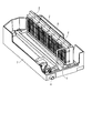
- FIG. 1 is a configuration diagram of a humidifier 1 according to the first embodiment.
- a humidifying element 2 is incorporated in the humidifying device 1.
- a blower 5 is incorporated on the upstream side or the downstream side of the humidifying element 2 to send indoor air to the humidifying element 2 and blow it out into the room again.
- the humidifying device 1 is connected to a humidifying element 2, a water supply pipe 3 that is connected to a water supply source such as a water supply facility and supplies humidifying water to the humidifying element 2, and water remaining without being humidified by the humidifying element 2 to the outside.
- a drain pipe 4 to be discharged a blower 5 for allowing the air flow to pass through the humidifying element 2, a control device 6 for operating the blower 5 and a water supply system electromagnetic valve (water supply valve 3a), etc.
- a drain pan 7 for draining.
- FIG. 2 is an enlarged view of the humidifying element 2 portion of the humidifying device 1.
- One or a plurality of humidifying elements 2 are directly installed on the drain pan 7.
- the ridge corners on both sides of the top structure of each humidifying element 2 are detachably held by guide rails (not shown) mounted on the partition wall and the front inner wall surface of the main body box.
- the humidifying element 2 is connected to a water supply system having a water supply valve 3 a for supplying and shutting off water for humidification, and a drain pipe 4 is connected to the drain pan 7.
- the water supply system for supplying humidifying water to the humidifying element 2 includes a water supply valve 3a for adjusting the pressure and flow rate of water supplied to the humidifying element 2, a strainer for preventing dust from entering the water supply system, and water supply for water supply. It is configured as a water channel including the pipe 3. It is desirable that all connection portions of the water supply system except for the connection portion with the water supply source side are concentrated in the drain pan 7.
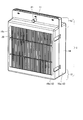
- FIG. 3 is a perspective view of the humidifying element 2.
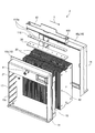
- FIG. 4 is an exploded perspective view of the humidifying element 2.
- FIG. 5 is a front view of the humidifying element 2.
- FIG. 6 is a cross-sectional view taken along line XX shown in FIG.
- the humidifying element 2 includes a large number of plate-like humidifiers 20 arranged along a first direction (a direction indicated by an arrow Y in FIG. 5) so as to provide a gap between them.
- a diffusion member (diffusion plate) 30 is in contact with the upper portion of the humidifier 20.
- the diffusion member 30 is formed so as to extend along the first direction, and the plurality of humidifiers 20 come into contact with the single diffusion member 30 together.
- the humidifier 20 there are a water reservoir 12 that stores water to be supplied to the humidifier 20 and a water supply port 11 that injects water from the water supply pipe 3 into the water reservoir 12. Further, below the humidifying body 20, there are a drainage section 13 and a drain outlet 13a for receiving and draining water remaining from the humidifying body 20 without being humidified.
- the humidifier 20 is housed and fixed inside the casing 10.
- the water supply port 11, the water storage unit 12, and the drainage unit 13 are formed in the casing 10.
- the casing 10 is formed with a structural wall 14 that connects a water storage portion 12 as an upper structure and a drainage portion 13 as a lower structure. Water accumulates from the water supply port 11 to the water storage unit 12, permeates the diffusion member 30, spreads to the humidifying body 20, and humidifies the air flowing through the gaps between the humidifying bodies 20. Excess water that has not evaporated in the humidifier 20 flows out of the casing 10 from the lower drainage 13.
- the casing 10 is formed by injection molding using thermoplastic plastic such as ABS resin, PS resin or PP resin.
- the casing 10 is divided into two parts, a casing 10a and a casing 10b.
- the humidifying body 20 is sandwiched between the casing 10a and the casing 10b, and the casing 10a and the casing 10b are joined together by combining the engaging portions 15 of the casing 10a and the casing 10b.
- the casing 10a and the casing 10b are provided with a portion that becomes the water storage portion 12, a portion that becomes the drainage port 13a, and an opening portion 10c that introduces humidified air into the humidifying body 20, respectively. Further, the casing 10 b is provided with a water supply port 11 for supplying water to the water storage unit 12. A storage space for storing the humidifying body 20 is provided inside the casing 10.
- Positioning protrusions 17 for restricting the position of the humidifying body 20 are provided in a portion of the casing 10 that contacts the humidifying body 20. Since the humidifying body 20 softens when it contains water and deforms due to the weight of the water, the flow between the humidifying bodies 20 is restricted by regulating the position of the humidifying body 20 at the outer peripheral portion of the humidifying body 20 in contact with the casing 10. The dimension of the path can be secured and air can flow uniformly.
- the water storage unit 12 may be formed integrally with the diffusion member 30 and stored in the casing 10.
- the water supply port 11 is connected to the water supply pipe 3 and is provided above the humidifying element 2 and on the upper surface side of the humidifying body 20 in order to supply water to the water storage unit 12.
- the shape may be adapted to the water supply pipe 3, and a convex band (barbing) may be formed over the circumference so as not to be easily removed, or may be tied with a hose band.
- the position of the water supply port 11 is not limited as long as water can be supplied from the upper part of the humidifying body 20, but if water leakage occurs from the joint between the water supply pipe 3 and the water supply port 11, By disposing on the upstream side of the humidified air, the water flying upstream by the flow of the airflow is also led to the downstream side, that is, the humidifying element 2 side, and the scattering distance of water to the surroundings can be reduced.
- the water storage unit 12 is provided above the humidifier 20.
- a plurality of water injection holes 12 a are formed on the bottom surface of the water reservoir 12.
- a cylindrical cylindrical wall surface 12b extending downward from the water injection hole 12a is formed on the outside of the water reservoir 12.
- a notch (communication port) 12c is formed at the tip of the cylindrical wall surface 12b. The tip end of the cylindrical wall surface 12 b contacts the diffusing member 30.
- a cylindrical water conduit 100 extending vertically is formed inside the water reservoir 12 at a position avoiding the water injection hole 12a. In the water conduit 100, an inflow port through which water flows into the water conduit 100 is formed at a position lower than the upper end of the water reservoir 12.
- the upper end of the water conduit 100 is at a position lower than the upper end of the outer wall of the water storage section 12, and the opening on the upper end side becomes the inflow port.
- an opening may be provided at a position lower than the outer wall of the water storage unit 12 to serve as an inlet.
- a plate-shaped water guide member 110 is sandwiched between the water storage unit 12 and the diffusion member 30. Moreover, the water storage part 12 and the diffusion member 30 are united together, and the integrated component is sandwiched and held between the casing 10a and the casing 10b. Further, a water level detection sensor 8 that detects the water level of the water storage unit 12 may be installed in the water storage unit 12. The detected water level may be fed back and the control device 6 may control the opening and closing of the water supply valve 3a.
- the diffusion member 30 is formed of a porous plate material. Since water is infiltrated and water is supplied to the humidifying body 20, the surface of the material is desirably hydrophilic, and the hydrophilicity improves permeability and increases the amount of water supply. Further, since the diffusing member 30 comes into contact with water, it is a porous material made of a material that is not easily deteriorated by water, for example, polyester or PP resin such as PET resin for resin, cellulose, titanium or copper, stainless steel, etc. It is desirable to be made of a quality material. Further, a hydrophilic treatment or the like may be performed to increase the hydrophilicity of the material surface.
- the humidifier 20 is formed of a porous plate-like material like the diffusion member 30. Suitable conditions are the same as those of the diffusing member 30, and the same material as that of the diffusing member 30 may be used.
- a convex portion 40 is provided on the surface of the humidifier 20. By the convex part 40, the space
- the convex portion 40 is formed by pressing a jig or the like against the humidifying body 20 and plastically deforming the portion. By alternately arranging two types of humidifying bodies 20 having different arrangement positions of the protrusions 40 on the humidifying body 20, there is a function of keeping the interval between the humidifying bodies 20 constant.
- the humidifying body only needs to be kept at a constant interval, and the humidifying body is held at a constant interval by meshing a comb with notches corresponding to the thickness of the humidifying body plate, or a plurality of undulating humidifications. There is no functional problem even if the structure is such that the gaps are maintained by stacking the bodies in a honeycomb shape.
- the lower end of the diffusing member 30 and the upper end of the humidifying body 20 are partly in contact with each other. If the diffusing member 30 and the humidifying body 20 are in contact with each other, water flows down due to the effect of surface tension. However, the lower end of the diffusing member 30 and the humidifying body are taken into account in consideration of variations during assembly and vibration during transportation. You may connect so that the upper end of 20 may be inserted mutually.
- the water supplied from the water supply port 11 flows into the water storage unit 12.
- the water that has flowed into the water storage unit 12 flows from the plurality of water injection holes 12 a on the bottom surface of the water storage unit 12, is absorbed by the diffusion member 30 through the cylindrical wall surface 12 b having the notches 12 c, and spreads inside the diffusion member 30. It flows down and reaches the lower end of the diffusing member 30.
- the amount of water drained and drained from the lower end of the humidifying body 20 is the amount of water obtained by subtracting the amount of water taken from the humidifying body 20 as humidified air from the amount of water supplied from the water supply port 11.
- the water level h stored in the water storage unit 12 is determined such that the flow rate Q1 passing through the water injection hole 12a is equal to the water supply amount Q from the water supply port 11. For this reason, when the hardness component of the feed water and evaporation residues such as silica and iron rust accumulate in the water injection hole 12a over time, a and b become smaller, and the water level h of the water storage section 12 becomes higher from the equation (3). Q1, that is, the amount of humidification is controlled to be constant.
- the humidifying element 2 that supplies water from the water storage section 12 provided on the upper portion of the humidifying body 20 through the water injection hole 12a and the diffusion member 30 has a function of controlling the humidification amount constant over time. From the dimensions of the water storage section 12 or the casing 10, there is an upper limit value that should be allowed for the water level to rise. In addition, from the formula (2), when a becomes small, it takes a long time to reach a constant water level, so it takes time to start the water supply and stabilize the humidification amount. It is not preferable in a humidifier. Therefore, it is necessary to prevent evaporation residue from being accumulated in the water injection hole 12a as much as possible even with time.
- FIG. 7 is a bottom view of the water reservoir 12 as viewed from below.
- FIG. 8 is a cross-sectional view of the periphery of the water reservoir 12.
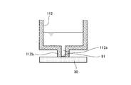
- FIG. 9 is a cross-sectional view of the periphery of the water reservoir 112 shown as a comparative example.
- a cylindrical wall surface 112b is formed at the lower end of the water injection hole 112a.
- the cylindrical wall surface 112b extends downward from the inner surface of the water injection hole 112a, but a notch is formed at the tip of the cylindrical wall surface 112b. Absent.
- FIG. 8 a cylindrical wall surface 12b having a notch 12c with a partly opened side surface is formed, and the inside of the cylindrical wall surface 12b is open to the atmosphere through the notch 12c. Even if the air bubbles 91 adhere to the air, the air bubbles 91 come into contact with the atmosphere, so that the air bubbles 91 disappear quickly and as a result, a good water flow state can be easily maintained and a stable humidification amount can be secured. .
- a communication port 18 is formed above the water storage unit 12 to communicate the outside of the casing 10 and the water storage unit 12. Thereby, the water storage part 12 is open
- stop of the humidification operation when humidification is unnecessary such as at night will be described.
- the humidifying operation of the humidifying device 1 may be stopped.
- bacteria and mold in the air adhere to the wet part and grow, there is a concern that the bacteria and mold spores are transported by the air passing through the surface of the humidifying element 2 and released into the room when the humidification operation is resumed. is there.
- As a method for suppressing the growth of such bacteria and molds it is effective to dry the humidifying element 2 as soon as possible.
- FIG. 10 is a cross-sectional view showing an example of the periphery of the water storage section 12.
- the bottom surface of the water storage section 12 is inclined so as to be lowest in the water injection hole 12 a portion. Therefore, after the water supply valve 3a is closed, the water in the water storage part 12 flows smoothly toward the water injection hole 12a. Therefore, the water in the water storage section 12 easily flows out to the outside through the water injection hole 12a, and early drying in the water storage section 12 can be achieved.
- FIG. 11 is a cross-sectional view showing an example of the periphery of the water storage section 12.
- the bottom surface of the water storage section 12 is formed with a curved surface, and is inclined so as to be the lowest in the water injection hole 12 a portion.
- the bottom face of the water storage part 12 may be comprised by the plane and the curved surface.
- the material of the water storage section 12 may be a water repellent material such as PP or PTFE, or the surface may be subjected to a water repellent treatment without using the water repellent material itself so that water does not easily stay.
- the water storage part 12, the diffusion member 30, the humidifier 20, and the casing 10 may be subjected to antibacterial treatment and fungicidal treatment from the viewpoint of hygiene.
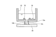
- FIG. 12 is a cross-sectional view showing an example of the periphery of the water storage unit 12.
- FIG. 13 is a cross-sectional view illustrating an example of the periphery of the water storage unit 12.
- the convex part 70 is provided in the bottom part of the water storage part 12 so that the water injection hole 12a may be enclosed.
- a recess 80 is provided at the bottom of the water reservoir 12 so as to surround the water injection hole 12 a.
- the evaporation residue 16 Since the evaporation residue 16 has a specific gravity greater than that of water, it accumulates and accumulates on the bottom surface of the water storage section 12. When the water in the water reservoir 12 flows toward the water injection hole 12a, the evaporation residue 16 deposited on the bottom surface also flows toward the water injection hole 12a.
- the convex part 70 is provided in the bottom part of the water storage part 12 so that the water injection hole 12a may be enclosed, the evaporation residue 16 is dammed up by the convex part 70, and the penetration
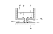
- FIG. 14 is a cross-sectional view showing an example of the periphery of the water storage section 12.
- a capturing member 90 that is a nucleus of the evaporation residue 16 is provided on the bottom surface of the water storage unit 12.
- the evaporation residue 16 in the water grows with the components of the capture member 90 as a core, and deposits and settles on the surface of the capture member 90, so Intrusion into 12a can be suppressed.
- the capturing member 90 is made of a material that becomes a growth nucleus for calcium carbonate, silica, iron, and the like contained in the supplied water.
- calcium carbonate is a substance containing calcium carbonate such as calcite and aragonite
- silica is a silicate compound such as quartz
- copper is suitable for iron.
- the capturing member 90 may be configured such that each component is separately disposed in the water storage unit 12, or may be used after being powdered, mixed and homogenized, and then solidified with a binder or the like.
- the material of the water storage section 12 may be a water repellent material such as PP or PTFE, or the surface may be subjected to a water repellent treatment without using the water repellent material itself so that water does not easily stay.
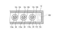
- FIG. 15 is a cross-sectional view showing an example of the periphery of the water storage section 12.
- 16 is a cross-sectional view taken along the line ZZ shown in FIG. In FIG. 16, the water conduit 100 is indicated by a broken line.
- a cylindrical water conduit 100 is formed inside the water reservoir 12 so as to avoid the water injection hole 12a and extend vertically.
- a water conduit opening hole 12 d that penetrates the bottom surface of the water reservoir 12 is formed.
- An enclosing wall 12e is formed outside the bottom surface of the water storage section 12 so as to protrude downward and surround the periphery of the water conduit opening hole 12d and the cylindrical wall surface 12b.
- the protruding amount of the cylindrical wall surface 12 b is equal to the protruding amount of the surrounding wall 12 e, and both of them are in contact with the diffusing member 30 at their tips.
- size which fits the inner side of the surrounding wall 12e is provided.
- a through hole 110a larger than the outer diameter of the cylindrical wall surface 12b is formed at a position corresponding to the water injection hole 12a (position overlapping the water injection hole 12a in plan view).
- the water guide member 110 is in contact with the diffusion member 30.
- the amount of water injection decreases.
- the water level h rises as described above. Since the upper end of the water conduit 100 is lower than the outer wall of the water reservoir 12, when the water level h rises, the water conduit 100 flows into the water conduit 100 without overflowing.
- the supplied water that has flowed into the water guide pipe 100 flows over the water guide member 110 and then flows down from the through hole 110a to the diffusion member 30. If the through hole 110 a is adjusted to an appropriate hole diameter, the supply water is evenly distributed to each through hole 110 a and flows down to the diffusion member 30. With this action, even when the amount of water injected from the water injection hole 12a decreases and the water level h increases significantly, the supply water from the water storage section 12 does not overflow, and water can be uniformly supplied to the diffusion member 30. When the water guide member 110 is not provided, a large amount of supplied water permeates the diffusion member 30 from the portion immediately below the water guide pipe opening hole 12d, so that uniform water supply becomes difficult. However, in this embodiment, the water guide member 110 The supply water can flow down to a position corresponding to the water injection hole 12a to achieve uniform water supply. Moreover, it becomes difficult for supply water to leak outside by enclosing with the surrounding wall 12e.
- the water guide pipe 100 is formed near the outer wall of the water storage section 12, more specifically, the outer wall is included in a part of the water guide pipe 100, but the water guide pipe is located at a position away from the outer wall. 100 may be formed.
- the notch 12c as a communication port formed at the tip of the cylindrical wall surface 12b may be any hole as long as it allows the inside of the cylindrical wall surface 12b to communicate with the outside to allow bubbles to escape.
- a communication port may be formed.
- bubbles are likely to be generated on the surface of the diffusing member 30, the bubbles can be easily released by forming a communication port on the tip side.
- uniform supply of water to the plurality of humidifying bodies 20 can be achieved. Moreover, the water supply to the humidification body 20 stabilized for a long period of time can be aimed at. Moreover, the humidification element 2 can be simplified to facilitate assembly. Further, the amount of humidification by the humidifying element 2 can be increased. In addition, hygiene can be improved.
Landscapes
- Engineering & Computer Science (AREA)
- Chemical & Material Sciences (AREA)
- Combustion & Propulsion (AREA)
- Mechanical Engineering (AREA)
- General Engineering & Computer Science (AREA)
- Air Humidification (AREA)
Abstract
Priority Applications (3)
| Application Number | Priority Date | Filing Date | Title |
|---|---|---|---|
| CN201480079354.8A CN106489053B (zh) | 2014-05-30 | 2014-12-09 | 加湿元件及加湿装置 |
| EP14893163.7A EP3150933B1 (fr) | 2014-05-30 | 2014-12-09 | Élément humidifiant et humidificateur |
| JP2016523101A JP6038407B2 (ja) | 2014-05-30 | 2014-12-09 | 加湿素子および加湿装置 |
Applications Claiming Priority (2)
| Application Number | Priority Date | Filing Date | Title |
|---|---|---|---|
| JP2014-113150 | 2014-05-30 | ||
| JP2014113150 | 2014-05-30 |
Publications (1)
| Publication Number | Publication Date |
|---|---|
| WO2015182014A1 true WO2015182014A1 (fr) | 2015-12-03 |
Family
ID=54698380
Family Applications (1)
| Application Number | Title | Priority Date | Filing Date |
|---|---|---|---|
| PCT/JP2014/082560 Ceased WO2015182014A1 (fr) | 2014-05-30 | 2014-12-09 | Élément humidifiant et humidificateur |
Country Status (4)
| Country | Link |
|---|---|
| EP (1) | EP3150933B1 (fr) |
| JP (1) | JP6038407B2 (fr) |
| CN (1) | CN106489053B (fr) |
| WO (1) | WO2015182014A1 (fr) |
Families Citing this family (1)
| Publication number | Priority date | Publication date | Assignee | Title |
|---|---|---|---|---|
| DE102023123386A1 (de) | 2023-08-30 | 2025-03-06 | Salino GmbH | Luftbefeuchtungseinrichtung |
Citations (4)
| Publication number | Priority date | Publication date | Assignee | Title |
|---|---|---|---|---|
| JPH04366336A (ja) * | 1991-06-12 | 1992-12-18 | Taikisha Ltd | 加湿器 |
| JP2003130401A (ja) * | 2001-10-23 | 2003-05-08 | Sharp Corp | 加湿装置 |
| JP2003185201A (ja) * | 2001-12-20 | 2003-07-03 | Orion Mach Co Ltd | エアプロセッサ |
| JP2007155182A (ja) * | 2005-12-02 | 2007-06-21 | Matsushita Electric Ind Co Ltd | 加湿装置 |
Family Cites Families (13)
| Publication number | Priority date | Publication date | Assignee | Title |
|---|---|---|---|---|
| SE391576B (sv) * | 1975-03-11 | 1977-02-21 | Svenska Flaektfabriken Ab | Anordning for befuktning av genom en kammare strommande luft |
| JPS62176629U (fr) * | 1986-04-30 | 1987-11-10 | ||
| US5226935A (en) * | 1989-12-08 | 1993-07-13 | Skandinavisk Miljo System A/S | Air humidification apparatus |
| JPH08178375A (ja) * | 1994-12-28 | 1996-07-12 | Japan Gore Tex Inc | 加湿装置 |
| US5853625A (en) * | 1997-06-27 | 1998-12-29 | Honeywell Inc. | Water distribution tray for a pad-type humidifier unit |
| US6572085B2 (en) * | 2001-05-15 | 2003-06-03 | Research Products Corporation | Humidifier with reversible housing and distribution tray overflow |
| JP2009180434A (ja) * | 2008-01-31 | 2009-08-13 | Sharp Corp | 加湿装置 |
| CN201497109U (zh) * | 2009-04-22 | 2010-06-02 | 深圳市联创实业有限公司 | 空气净化加湿机 |
| CN201513996U (zh) * | 2009-09-25 | 2010-06-23 | 上海科绿特环保科技有限公司 | 气候箱露点加湿装置 |
| CN102052725A (zh) * | 2009-11-11 | 2011-05-11 | 田志坚 | 高能效比空气加湿器 |
| CN201652674U (zh) * | 2010-02-23 | 2010-11-24 | 田志坚 | 高效节能空气加湿器 |
| JP2012154547A (ja) * | 2011-01-25 | 2012-08-16 | Zojirushi Corp | 加湿器 |
| US9285133B2 (en) * | 2012-01-21 | 2016-03-15 | Air System Components, Inc. | Air humidification system |
-
2014
- 2014-12-09 WO PCT/JP2014/082560 patent/WO2015182014A1/fr not_active Ceased
- 2014-12-09 EP EP14893163.7A patent/EP3150933B1/fr active Active
- 2014-12-09 JP JP2016523101A patent/JP6038407B2/ja active Active
- 2014-12-09 CN CN201480079354.8A patent/CN106489053B/zh active Active
Patent Citations (4)
| Publication number | Priority date | Publication date | Assignee | Title |
|---|---|---|---|---|
| JPH04366336A (ja) * | 1991-06-12 | 1992-12-18 | Taikisha Ltd | 加湿器 |
| JP2003130401A (ja) * | 2001-10-23 | 2003-05-08 | Sharp Corp | 加湿装置 |
| JP2003185201A (ja) * | 2001-12-20 | 2003-07-03 | Orion Mach Co Ltd | エアプロセッサ |
| JP2007155182A (ja) * | 2005-12-02 | 2007-06-21 | Matsushita Electric Ind Co Ltd | 加湿装置 |
Also Published As
| Publication number | Publication date |
|---|---|
| JP6038407B2 (ja) | 2016-12-07 |
| EP3150933A4 (fr) | 2018-01-24 |
| EP3150933B1 (fr) | 2019-01-30 |
| EP3150933A1 (fr) | 2017-04-05 |
| CN106489053A (zh) | 2017-03-08 |
| JPWO2015182014A1 (ja) | 2017-04-20 |
| CN106489053B (zh) | 2019-05-03 |
Similar Documents
| Publication | Publication Date | Title |
|---|---|---|
| JP6038406B2 (ja) | 加湿素子および加湿装置 | |
| JP6038390B2 (ja) | 加湿素子および加湿装置 | |
| JP6636148B2 (ja) | 加湿素子、加湿装置、空気調和機および換気装置 | |
| JP6038407B2 (ja) | 加湿素子および加湿装置 | |
| JP2015183991A (ja) | 加湿素子および加湿装置 | |
| JP6169053B2 (ja) | 加湿素子および加湿装置 | |
| JP2015183992A (ja) | 加湿素子および加湿装置 | |
| JP2016176635A (ja) | 加湿素子および加湿装置 | |
| JP6223285B2 (ja) | 加湿素子および加湿装置 | |
| WO2023021552A1 (fr) | Élément d'humidification, dispositif d'humidification, dispositif de ventilation et climatiseur | |
| JP6742517B2 (ja) | 加湿素子、加湿装置、空気調和機および換気装置 | |
| JP6041757B2 (ja) | 加湿エレメント及び加湿装置 | |
| JP2015183989A (ja) | 加湿素子および加湿装置 | |
| JP4953787B2 (ja) | 加湿装置 | |
| JP7236872B2 (ja) | 加湿素子、加湿装置、空気調和機および換気装置 | |
| JP2015183990A (ja) | 加湿素子および加湿装置 | |
| JP6218688B2 (ja) | 加湿素子および加湿装置 | |
| JP7186648B2 (ja) | 加湿素子、加湿装置、換気装置及び空気調和機 | |
| JP6453570B2 (ja) | 加湿素子および加湿装置 | |
| JP7254048B2 (ja) | 加湿素子、加湿装置、空気調和機および換気装置 | |
| JP2015028399A (ja) | 加湿素子及びそれを備えた加湿装置 | |
| JPH01174836A (ja) | 自然蒸発式加湿器 |
Legal Events
| Date | Code | Title | Description |
|---|---|---|---|
| 121 | Ep: the epo has been informed by wipo that ep was designated in this application |
Ref document number: 14893163 Country of ref document: EP Kind code of ref document: A1 |
|
| ENP | Entry into the national phase |
Ref document number: 2016523101 Country of ref document: JP Kind code of ref document: A |
|
| NENP | Non-entry into the national phase |
Ref country code: DE |
|
| REEP | Request for entry into the european phase |
Ref document number: 2014893163 Country of ref document: EP |
|
| WWE | Wipo information: entry into national phase |
Ref document number: 2014893163 Country of ref document: EP |