WO2015182015A1 - Dispositif électronique - Google Patents
Dispositif électronique Download PDFInfo
- Publication number
- WO2015182015A1 WO2015182015A1 PCT/JP2014/083572 JP2014083572W WO2015182015A1 WO 2015182015 A1 WO2015182015 A1 WO 2015182015A1 JP 2014083572 W JP2014083572 W JP 2014083572W WO 2015182015 A1 WO2015182015 A1 WO 2015182015A1
- Authority
- WO
- WIPO (PCT)
- Prior art keywords
- line
- power
- power supply
- unit
- electronic device
- Prior art date
- Legal status (The legal status is an assumption and is not a legal conclusion. Google has not performed a legal analysis and makes no representation as to the accuracy of the status listed.)
- Ceased
Links
Images


Classifications
-
- H—ELECTRICITY
- H05—ELECTRIC TECHNIQUES NOT OTHERWISE PROVIDED FOR
- H05B—ELECTRIC HEATING; ELECTRIC LIGHT SOURCES NOT OTHERWISE PROVIDED FOR; CIRCUIT ARRANGEMENTS FOR ELECTRIC LIGHT SOURCES, IN GENERAL
- H05B47/00—Circuit arrangements for operating light sources in general, i.e. where the type of light source is not relevant
- H05B47/10—Controlling the light source
- H05B47/105—Controlling the light source in response to determined parameters
-
- H—ELECTRICITY
- H02—GENERATION; CONVERSION OR DISTRIBUTION OF ELECTRIC POWER
- H02J—ELECTRIC POWER NETWORKS; CIRCUIT ARRANGEMENTS OR SYSTEMS FOR SUPPLYING OR DISTRIBUTING ELECTRIC POWER; SYSTEMS FOR STORING ELECTRIC ENERGY
- H02J9/00—Circuit arrangements for emergency or stand-by power supply, e.g. for emergency lighting
- H02J9/005—Circuit arrangements for emergency or stand-by power supply, e.g. for emergency lighting using a power saving mode
-
- H—ELECTRICITY
- H05—ELECTRIC TECHNIQUES NOT OTHERWISE PROVIDED FOR
- H05B—ELECTRIC HEATING; ELECTRIC LIGHT SOURCES NOT OTHERWISE PROVIDED FOR; CIRCUIT ARRANGEMENTS FOR ELECTRIC LIGHT SOURCES, IN GENERAL
- H05B45/00—Circuit arrangements for operating light-emitting diodes [LED]
- H05B45/30—Driver circuits
-
- H—ELECTRICITY
- H05—ELECTRIC TECHNIQUES NOT OTHERWISE PROVIDED FOR
- H05B—ELECTRIC HEATING; ELECTRIC LIGHT SOURCES NOT OTHERWISE PROVIDED FOR; CIRCUIT ARRANGEMENTS FOR ELECTRIC LIGHT SOURCES, IN GENERAL
- H05B45/00—Circuit arrangements for operating light-emitting diodes [LED]
- H05B45/50—Circuit arrangements for operating light-emitting diodes [LED] responsive to malfunctions or undesirable behaviour of LEDs; responsive to LED life; Protective circuits
- H05B45/56—Circuit arrangements for operating light-emitting diodes [LED] responsive to malfunctions or undesirable behaviour of LEDs; responsive to LED life; Protective circuits involving measures to prevent abnormal temperature of the LEDs
-
- H—ELECTRICITY
- H02—GENERATION; CONVERSION OR DISTRIBUTION OF ELECTRIC POWER
- H02J—ELECTRIC POWER NETWORKS; CIRCUIT ARRANGEMENTS OR SYSTEMS FOR SUPPLYING OR DISTRIBUTING ELECTRIC POWER; SYSTEMS FOR STORING ELECTRIC ENERGY
- H02J9/00—Circuit arrangements for emergency or stand-by power supply, e.g. for emergency lighting
- H02J9/04—Circuit arrangements for emergency or stand-by power supply, e.g. for emergency lighting in which the distribution system is disconnected from the normal source and connected to a standby source
- H02J9/06—Circuit arrangements for emergency or stand-by power supply, e.g. for emergency lighting in which the distribution system is disconnected from the normal source and connected to a standby source with automatic change-over, e.g. UPS systems
Definitions
- Embodiments described herein relate generally to an electronic device.
- This embodiment provides an electronic device that can improve convenience.
- the electronic device is an electronic device that can be switched between supply and cut-off of AC power by a switch outside the device, and a determination unit that determines whether or not the AC power is supplied, and a conduction state of the switch A second power source different from the AC power source, an output unit, and a control unit.
- the control unit based on the outputs of the determination unit and the detection unit, at least cut off the power to be supplied to the output unit, supply from the AC power supply, or supply from the second power supply, Either.
- FIG. 1 is a front view illustrating an example of an electronic apparatus according to the first embodiment.
- 2 is a cross-sectional view taken along line F2-F2 of the electronic device shown in FIG.
- FIG. 3 is a cross-sectional view schematically showing the function of the light guide portion of the electronic device shown in FIG. 4 is a diagram showing a system configuration example of the electronic device shown in FIG.
- FIG. 5 is a diagram showing a system configuration example of the electronic device shown in FIG.
- FIG. 6 is a diagram showing an example of the pull-up circuit and the voltage monitoring circuit shown in FIG.
- FIG. 7 is a diagram showing a modification of the pull-up circuit and the voltage monitoring circuit shown in FIG.
- FIG. 8 is a diagram showing an operation state of the electronic device shown in FIG. FIG.
- FIG. 9 is a diagram showing an operation state of the electronic device shown in FIG.
- FIG. 10 is a diagram illustrating an operation state of the electronic device illustrated in FIG.
- FIG. 11 is a diagram showing an operation state of the electronic device shown in FIG.
- FIG. 12 is a diagram showing an operation state of the electronic device shown in FIG.
- FIG. 13 is a diagram showing a first modification of the system configuration of the electronic device shown in FIG.
- FIG. 14 is a diagram illustrating a second modification of the system configuration of the electronic device illustrated in FIG. 1.
- FIG. 15 is a diagram showing a third modification of the system configuration of the electronic device shown in FIG.
- FIG. 16 is a diagram showing a fourth modification of the system configuration of the electronic device shown in FIG. FIG.
- FIG. 17 is a diagram illustrating a fourth modification of the system configuration of the electronic device illustrated in FIG. 1.
- FIG. 18 is a diagram illustrating a fifth modification of the system configuration of the electronic device illustrated in FIG. 1.
- FIG. 19 is a diagram illustrating a system configuration example of an electronic apparatus according to the second embodiment.
- FIG. 20 is a diagram showing a modification of the system configuration of the electronic device shown in FIG.
- FIG. 21 is a front view showing an example of the electronic device shown in FIG.
- FIG. 22 is a diagram illustrating a system configuration example of an electronic apparatus according to the third embodiment.
- FIG. 23 is a cross-sectional view illustrating an example of an electronic apparatus according to the fourth embodiment.
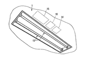
- FIG. 24 is a perspective view illustrating an example of an electronic apparatus according to the fifth embodiment.
- FIG. 25 is a diagram illustrating a system configuration example of an electronic apparatus according to the sixth embodiment.
- FIG. 1 to 12 show an electronic apparatus 1 according to the first embodiment.
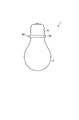
- FIG. 1 shows an external appearance of the electronic device 1.
- the electronic device 1 according to the present embodiment is, for example, a lighting device.
- the structure which concerns on this embodiment is widely applicable not only to an illuminating device but to various electronic devices, such as a ventilation fan and an air blower, for example.
- the electronic device 1 is, for example, an LED (Light Emitting Diode) lamp that is used by being attached to a socket provided on the ceiling of the room.
- the electronic device 1 is not limited to an LED lamp, and may be, for example, a halogen lamp, an incandescent bulb, a fluorescent lamp, or the like, and is not particularly limited.
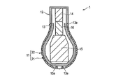
- FIG. 2 shows a cross section of the electronic device 1.
- the electronic device 1 includes a globe 11, a base 12, a light emitting unit 13, a power supply unit 14, a battery 15, and a control unit 16.
- the gravity direction is defined as the lower side and the ceiling direction is defined as the upper side, with the attitude of the electronic device 1 mounted on the socket provided on the indoor ceiling as a reference.
- the globe 11 irradiates light from the surface when the electronic device 1 functions as illumination.
- the globe 11 includes a heat transfer member 21 and a light guide unit 22.
- the heat transfer member 21 has, for example, a general light bulb shape as shown in FIG. More specifically, in the heat transfer member 21, a spherical head 21a and a truncated cone-shaped body 21b are integrally formed.
- the inside of the heat transfer member 21 is formed hollow, for example.
- One end of the body portion 21b has an opening that allows the space inside the heat transfer member 21 to communicate with the outside.
- the material of the heat transfer member 21 is preferably a metal material having excellent thermal conductivity such as aluminum.
- the heat transfer member 21 conducts heat generated by the light emitting unit 13 inside the heat transfer member 21 and transfers part of the heat to the light guide unit 22.
- the light guide 22 covers the heat transfer member 21 along the outer shape of the heat transfer member 21.
- the light guide unit 22 is a light-transmissive member such as glass or synthetic resin, and guides light therein. Similar to the heat transfer member 21, the light guide 22 has a spherical head 22 a and a truncated cone-shaped body 22 b. For example, a scattering mark that scatters light by silk printing, cutting, or the like is provided on the entire outer surface or inner surface of the light guide 22.
- the light emitting unit 13 includes at least one light emitting element 13a such as an LED. As shown in FIG. 2, the light emitting element 13 a is provided on the end surface of the base 12 and the outer surface of the heat transfer member 21, for example, and is in contact with the light guide unit 22. In other words, the light emitting element 13 a is located inside the light guide unit 22 and irradiates light inside the light guide unit 22.
- the light emitting unit 13 may be a substrate having one or more light emitting elements 13a.
- the light emitting unit 13 is an example of a “load unit” and an “output unit” of the electronic device 1.
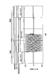
- FIG. 3 schematically shows the function of the light guide unit 22.
- the light emitted from the light emitting unit 13 goes straight or refracts in the light guide unit 22.
- light satisfying the total reflection condition at the interface between the light guide unit 22 and the external space repeatedly undergoes total reflection at the interface between the light guide unit 22 and the external space, and the interface between the light guide unit 22 and the heat transfer member 21.
- the light is guided (propagated) through the light guide 22.
- the light that is scattered by the scattering mark and does not satisfy the total reflection condition is irradiated from the light guide 22 to the external space without being totally reflected at the interface between the light guide 22 and the external space. Thereby, light is irradiated from the outer surface of the light guide unit 22, that is, the entire surface of the globe 11.
- the base 12 is an electrical and mechanical connection portion when the electronic device 1 is fixed to the socket by, for example, screwing.
- the base 12 is formed in a hollow shape, and a female screw or a male screw for mounting on the socket is provided on the surface.
- the material of the base 12 is preferably a conductive metal material such as aluminum.
- an example of a casing 24 (case) of the electronic device 1 is formed by the globe 11 and the base 12.
- the power supply unit 14, the battery 15, and the control unit 16 are accommodated in the housing 24.
- the battery 15 and the control unit 16 are located inside the globe 11.
- the battery 15 and the control unit 16 may be located inside the base 12.
- the power supply unit 14 may be located inside the globe 11.
- the battery 15 is positioned below the power supply unit 14 and the control unit 16, for example, inside the globe 11.
- the battery 15 is a component that generates heat during charging and discharging.
- the air flowing around the electronic device 1 is warmed by the electronic device 1 and flows in a direction opposite to gravity (that is, upward) by natural convection. For this reason, if the battery 15 is provided as low as possible inside the electronic device 1, heat radiation is easily promoted by cooler air, and an increase in temperature of the electronic device 1 is easily suppressed.
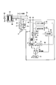
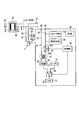
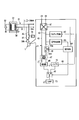
- FIG. 4 schematically shows the system configuration of the electronic apparatus 1.
- a case where the electronic apparatus 1 is connected to general household wiring will be described as an example.
- electric power is supplied to the house wiring (hereinafter, power supply line 31) from an external AC power supply 32.
- the AC power supply 32 is an example of each of “first power supply”, “external power supply”, and “commercial power supply”.
- a high voltage such as 6600 V is converted into AC 100 V or AC 200 V by a pole transformer 33 (transformer) provided on a telegraph pole outside the house, and the AC power supply 32 is supplied to an indoor power supply line 31. .
- the electronic apparatus 1 is connected to the power supply line 31 through, for example, a socket, and power is supplied from the AC power supply 32 through the power supply line 31.
- the electronic device 1 may be connected to the power supply line 31 via, for example, an appliance with a switch (for example, an extension cord or a tap) and an outlet instead of the socket.
- the switch corresponds to an example of “a switch provided outside the device” like a wall switch 34 described later.
- the power supply line 31 includes, for example, a hot line 35 (first wiring, first electric wire), a cold line 36, and a ground wire 37 (ground line, second wiring, second electric wire). .
- the power supply line 31 may include only the hot line 35 and the ground line 37.
- the ground wire 37 may be referred to as a cold wire.
- the “first wiring” (first electric wire) is an electric wire to which actual power (voltage) is supplied.
- the “second wiring” (second electric wire) is an electric wire that becomes a ground potential.
- a switch 34 (manual switch) is provided in the middle of the power supply line 31.
- the switch 34 is an example of “a switch provided outside the device” and is located outside the electronic device 1.
- the switch 34 is a wall switch provided on an indoor wall surface, for example, and can be operated indoors.
- the power supply line 31 is switched between supply and interruption of the AC power supply 32 by a switch 34.
- the electronic device 1 is an example of a device that is connected to the power supply line 31 and can be switched between supply and interruption of the AC power supply 32 by the switch 34.
- the switch 34 can be manually operated by a user, for example.
- the switch 34 is a one-sided cut type in which only the hot wire 35 is turned on or off among the hot wire 35 and the ground wire 37. Note that the switch 34 may be a double-cut type in which both the hot wire 35 and the ground wire 37 are conducted or cut off, as shown in FIG.
- the switch 34 is not limited to a wall switch, and may be a switch with a string hanging from the ceiling, for example, or another type of switch.
- the switch 34 is referred to as a “wall switch 34” for convenience of explanation.
- a first portion 35a and a second portion 35b of the hot line 35 are defined.
- the first portion 35 a is a portion located between the wall switch 34 and the AC power supply 32 in the hot wire 35.
- the second portion 35 b is a portion located between the wall switch 34 and the electronic device 1 in the hot wire 35.
- the electronic device 1 includes a power supply line 41 that is electrically connected to the power supply line 31.
- the power supply line 41 includes a first line 42 (first power supply line) and a second line 43 (second power supply line).
- the first line 42 is electrically connected to the hot line 35 of the power supply line 31. That is, the first line 42 is connected to the AC power source 32 via the switch 34.
- a first connection portion 44 (first terminal portion) connected to the hot line 35 is provided at an end portion of the first line 42.
- the 1st connection part 44 is provided in the center part of the end surface (bottom surface) of the nozzle
- the second line 43 is electrically connected to the ground line 37 of the power supply line 31.
- a second connection portion 45 (second terminal portion) connected to the ground wire 37 is provided at the end of the second line 43.
- the 2nd connection part 45 is provided in the outer peripheral surface of the nozzle
- the electronic device 1 includes the power supply unit 14, the battery 15, and the control unit 16 as described above.
- the power supply unit 14 includes a transformer 47 and a rectifier 48 (rectifier unit).
- the first line 42 and the second line 43 of the power supply line 41 are connected by a transformer 47.
- the transformer 47 is supplied with an alternating current via the power supply line 41 and the power supply line 31.
- the rectifier 48 converts the alternating current supplied to the transformer 47 into a direct current.
- the battery 15 is an example of a “second power source”, and is an internal power source (secondary battery) provided inside the electronic device 1.
- the battery 15 is charged by using, for example, a direct current rectified by the rectifier 48 and can supply power to the electronic device 1 when necessary.
- the power supply unit 14 further includes a power supply switching unit 49 (power supply switching circuit).
- the power supply switching unit 49 is located between the rectifier 48 and the battery 15 and the light emitting unit 13. Based on the control signal from the control unit 16, the power supply switching unit 49 can switch whether the power supplied to the light emitting unit 13 is supplied from the rectifier 48, supplied from the battery 15, or shut off.
- An example of the power supply switching unit 49 includes a first state in which the rectifier 48 and the light emitting unit 13 are electrically connected, a second state in which the battery 15 and the light emitting unit 13 are electrically connected, and both the rectifier 48 and the battery 15. And the third state in which the light emitting unit 13 is turned off. Instead of this, the power supply switching unit 49 switches only between the first state in which the rectifier 48 and the light emitting unit 13 are conducted and the second state in which the battery 15 and the light emitting unit 13 are conducted. It may be possible. That is, since the power is not supplied from the rectifier 48 in the state where the wall switch 34 is turned off, the power supplied to the light emitting unit 13 can be cut off even when the rectifier 48 and the light emitting unit 13 are in conduction.
- FIG. 4 schematically shows the system configuration of the control unit 16.
- the control unit 16 is an example of each of “control means” and “apparatus control device”.
- the control unit 16 includes a determination unit 51, a detection unit 52, and a control unit 53.
- the determination unit 51 is electrically connected to the first line 42 and determines whether the AC power supply 32 is supplied.
- the detection unit 52 (state detection unit) is electrically connected to the first line 42 and detects the conduction state of the wall switch 34.
- the detection unit 52 detects the conduction state of the wall switch 34 via the power supply line 31 in a state where the determination unit 51 determines that the AC power supply 32 is not supplied, for example.
- the control unit 53 Based on the outputs of the determination unit 51 and the detection unit 52, the control unit 53 cuts at least the power supplied to the electronic device 1 (for example, the power supplied to the light emitting unit 13) or is supplied from the AC power supply 32, Alternatively, it can be supplied from the battery 15.
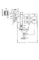
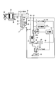
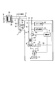
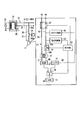
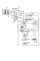
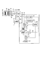
- FIG. 5 shows a specific configuration example for realizing the determination unit 51, the detection unit 52, and the control unit 53.
- the control unit 16 includes a relay 61, a pull-up circuit 62, a voltage monitoring circuit 63, and a control circuit 64.
- the relay 61 is an example of a “switching element” and a “change unit”, and changes the conduction state of the first line 42 based on a control signal from the control circuit 64. More specifically, the relay 61 is inserted in series in the middle of the first line 42.
- the relay 61 is, for example, an electronically controlled relay, but is not limited to this.
- the relay 61 is opened (becomes nonconductive)
- the first line 42 is cut off. For this reason, when the relay 61 is opened with the wall switch 34 turned off, the first line 42 and the hot line 35 between the relay 61 and the wall switch 34 are in an open state (floating state, in which the potential is not determined). )become.
- a first portion 42a and a second portion 42b of the first line 42 are defined.
- the first portion 42 a is a portion located between the relay 61 and the first connection portion 44 in the first line 42.
- the second portion 42 b is a portion located between the relay 61 and the transformer 47 in the first line 42.
- the second portion 42 b is connected to the ground wire 37 via the transformer 47 and the second line 43.
- the pull-up circuit 62 is electrically connected to the first portion 42a of the first line 42, and applies a predetermined DC voltage (for example, 3.3V) to the first portion 42a of the first line 42.
- the pull-up circuit 62 is an example of a “potential setting unit (potential setting circuit)” and a “setting unit”, and the first line between the relay 61 and the switch 34 without the supply of the AC power supply 32. 42 is set to a predetermined potential (predetermined voltage). That is, the pull-up circuit 62 sets the first portion 42a of the first line 42 and the second portion 35b of the hot line 35 to a predetermined potential when the relay 61 is opened with the wall switch 34 turned off. .
- a third line 66 is provided between the pull-up circuit 62 and the battery 15.
- the pull-up circuit 62 is supplied with DC power from the battery 15 via the third line 66. That is, the pull-up circuit 62 is a voltage source to which a voltage is supplied from, for example, the battery 15.
- the first portion 42a of the first line 42 is electrically connected to the transformer of the pole transformer 33 via the hot line 35. And is connected to ground in terms of direct current. For this reason, even if a predetermined voltage is applied to the first line 42 by the pull-up circuit 62, the potential of the first line 42 is substantially the ground potential (near 0V). That is, the potential of the first line 42 is changed by switching the wall switch 34.
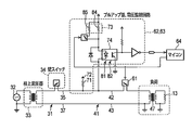
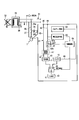
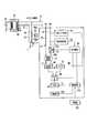
- FIG. 6 shows an example of a more specific configuration for realizing the pull-up circuit 62 and the voltage monitoring circuit 63.
- the pull-up circuit 62 has a first resistor 71 (first resistance element) connected to the first line 42.
- the first resistor 71 is provided between the predetermined voltage terminal 72 and the first line 42.
- a DC voltage is supplied to the voltage terminal 72 from the battery 15 through the third line 66, for example.
- the pull-up circuit 62 applies a predetermined voltage to the first line 42 via the first resistor 71 to set the first line 42 to a predetermined potential.
- the pull-up circuit 62 sets the hot line 35 to a predetermined potential by applying a predetermined voltage to the hot line 35 via the first line 42.
- the voltage monitoring circuit 63 is electrically connected to the first portion 42 a of the first line 42.
- the voltage monitoring circuit 63 monitors the potential of the first portion 42 a of the first line 42. In other words, the voltage monitoring circuit 63 detects the potential of the second portion 35 b of the hot line 35 via the first portion 42 a of the first line 42.
- the voltage monitoring circuit 63 outputs, for example, a logic signal that is high when the voltage level is higher than a predetermined voltage level and low when the voltage is not higher than the predetermined voltage level.
- the voltage monitoring circuit 63 sends at least three types of logic signals corresponding to the potential state of the first line 42 to the control circuit 64.
- the voltage monitoring circuit 63 is an example of a “measurement unit”, measures the voltage of the first line 42, and outputs the measurement result.
- This measurement result is either the voltage of the AC power supply 32, the predetermined voltage set by the pull-up circuit 62, or another voltage (third voltage).
- the voltage monitoring circuit 63 sends a first signal to the control circuit 64 when power is supplied to the first line 42 from the AC power supply 32.
- the first signal is a toggle signal corresponding to the frequency of the AC power supply 32, for example.
- the “toggle signal” is a signal in which a first voltage (for example, High) and a second voltage (for example, Low) are alternately repeated.
- the toggle signal of the present embodiment is a signal in which the first voltage and the second voltage alternately change at a frequency of 50 Hz or 60 Hz, for example.
- the voltage monitoring circuit 63 sends a second signal to the control circuit 64 when the first portion 42a of the first line 42 is at the predetermined potential set by the pull-up circuit 62.
- the second signal is a signal fixed to, for example, a first voltage (for example, High).
- the voltage monitoring circuit 63 sends a third signal to the control circuit 64 when the detection potential of the first portion 42a of the first line 42 is lower than the predetermined potential set by the pull-up circuit 62.
- the voltage monitoring circuit 63 sends a third signal to the control circuit 64.
- the third signal is a signal fixed to, for example, a second voltage (for example, Low).
- the voltage monitoring circuit 63 includes a second resistor 73 (second resistor element) and a photocoupler 74.
- the second resistor 73 is connected to the first line 42.
- the input part of the photocoupler 74 is connected in series between the second resistor 73 and the first line 42, for example.
- the output unit of the photocoupler 74 is connected to a microcomputer that is an example of the control circuit 64.
- the photocoupler 74 generates a binary detection voltage of High or Low based on the presence / absence of a current flowing through the second resistor 73.
- the photocoupler 74 outputs the presence / absence of a current flowing through the second resistor 73 to the control circuit 64 as a detection signal.
- the control circuit 64 is an example of a “comparator” that compares the output of the photocoupler 74 with a predetermined value.
- the control circuit 64 controls the opening / closing of the relay 61 and the state of the power supply switching unit 49 according to the contents of the logic signal obtained from the voltage monitoring circuit 63. Specifically, the control circuit 64 determines that power is supplied from the AC power supply 32 when the first signal is input from the voltage monitoring circuit 63. More specifically, the control circuit 64 counts the number of transition edges of the detected voltage High and Low within a predetermined time, and when it is within a predetermined range, the AC power supply 32 is supplied, The case is determined that the AC power supply 32 is not supplied. When it is determined that the AC power supply 32 is supplied, the control circuit 64 controls the relay 61 to be closed. The control circuit 64 further sends a control signal to the power supply switching unit 49 to control the power supply switching unit 49 so that power is supplied from the AC power supply 32 to the light emitting unit 13.
- the control circuit 64 determines that the AC power supply 32 is not supplied when the first signal is not input from the voltage monitoring circuit 63. In this case, the control circuit 64 controls the relay 61 to be opened. That is, the control circuit 64 changes the conduction state between the first portion 42 a of the first line 42 and the ground line 37 when the pull-up circuit 62 applies a voltage to the hot line 35 via the first line 42.
- the relay 61 is controlled to perform (for example, shut off).
- the voltage monitoring circuit 63 detects the conduction state of the wall switch 34 based on the potential of the first line 42 (the potential of the hot line 35) with the relay 61 opened.
- the control circuit 64 receives a logic signal from the voltage monitoring circuit 63 with the relay 61 opened, and when the second signal is input from the voltage monitoring circuit 63, the wall switch 34 is turned off (non-conducting state). Is determined). In this case, the control circuit 64 controls the power supply switching unit 49 so as to cut off the supply of power to the light emitting unit 13.
- the control circuit 64 receives a logic signal from the voltage monitoring circuit 63 with the relay 61 open, and when the third signal is input from the voltage monitoring circuit 63, the wall switch 34 is turned on (conduction). Is in a state). In this case, the control circuit 64 controls the power supply switching unit 49 so that power is supplied from the battery 15 to the light emitting unit 13.
- the determination unit 51 includes the voltage monitoring circuit 63 and a part of the control circuit 64.
- the detection unit 52 includes a relay 61, a pull-up circuit 62, a voltage monitoring circuit 63, and a control circuit 64.
- the determination unit 51 and the detection unit 52 share the voltage monitoring circuit 63 and the control circuit 64.
- the control unit 53 is configured by a part of the control circuit 64.
- the determination unit 51 includes a voltage change detection unit 81 that detects a voltage change of the first line 42 using the second resistor 73 and the photocoupler 74, and detects the voltage change within a predetermined time. It is determined whether or not the power supply 32 is supplied.
- the detection unit 52 includes a potential detection unit 82 that detects the conduction state of the wall switch 34 based on the potential set by the pull-up circuit 62 using the second resistor 73 and the photocoupler 74. That is, the voltage change detection unit 81 and the potential detection unit 82 share the second resistor 73 and the photocoupler 74.
- the resistance value of the second resistor 73 can be changed according to whether or not the AC power supply 32 is supplied.
- the resistance value of the second resistor 73 is variably controlled by the control unit 53 so as to be smaller in a state where the AC power supply 32 is not supplied than in a state where the AC power supply 32 is supplied.
- the second resistor 73 includes, for example, a first resistor element 84 and a second resistor element 85 that are electrically provided in parallel.
- the resistance value of the first resistance element 84 is larger than the resistance value of the second resistance element 85.
- the second resistor 73 is composed of only the first resistor element 84 in a normal state, for example, and has a relatively large resistance value. For this reason, even when, for example, an AC voltage of 100 V is supplied, the flowing current value can be kept relatively small.
- the control circuit 64 controls the second resistor 73 so as to connect the first resistance element 84 and the second resistance element 85 in parallel.
- the resistance value of the second resistor 73 is smaller than when the second resistor 73 is configured only by the first resistor element 84. For this reason, even when a DC voltage of 3.3 V, for example, is supplied, the flowing current value can be set to a magnitude suitable for detection.
- the control signal of the control circuit 64 that controls the second resistor 73 may be the same as (synchronized with) the control signal that controls the relay 61, for example.
- FIG. 7 shows a modification of the pull-up circuit 62 and the voltage monitoring circuit 63.
- the first resistor 71 and the second resistor 73 are combined as one resistor portion.
- the first resistor 71 and the second resistor 73 share at least one resistor element 84.
- the first resistor 71 and the second resistor 73 share the first resistor element 84 and the second resistor element 85. According to such a configuration, substantially the same function as the configuration shown in FIG. 6 can be realized, and the number of parts can be reduced.
- FIG. 8 shows the operation of the electronic apparatus 1 when the wall switch 34 is turned on in a normal state.
- the voltage monitoring circuit 63 sends the first signal (toggle signal) to the control circuit 64 based on the AC power supply 32.
- the control circuit 64 receives the first signal, determines that the AC power supply 32 is supplied, and controls the relay 61 to be closed. Further, the control circuit 64 controls the power supply switching unit 49 so that power is supplied to the light emitting unit 13 from the AC power supply 32. Thereby, the light emitting unit 13 can emit light when power is supplied from the AC power supply 32.
- “normal” means that the AC power supply 32 is supplied.
- FIG. 9 shows the operation of the electronic apparatus 1 when the wall switch 34 is turned off in a normal state.
- the first signal is not input from the voltage monitoring circuit 63 to the control circuit 64.
- the control circuit 64 determines that the AC power supply 32 is not supplied because there is no input of the first signal, and controls the relay 61 to open.
- the pull-up circuit 62 applies a predetermined DC voltage to the first portion 42a of the first line 42 in a state where the relay 61 is opened. As described above, when the wall switch 34 is turned off, the first portion 42 a of the first line 42 and the second portion 35 b of the hot line 35 are in an open state, and are set to a predetermined potential by the pull-up circuit 62. Is done.
- the voltage monitoring circuit 63 detects the potential of the first line 42, and when the predetermined potential set by the pull-up circuit 62 is detected, sends the second signal (for example, a signal fixed to High) to the control circuit 64. . Based on the second signal, the control circuit 64 controls the power supply switching unit 49 so as to cut off the power supply to the light emitting unit 13. As a result, the light emitting unit 13 is turned off.
- the second signal for example, a signal fixed to High
- FIG. 10 shows the operation of the electronic device 1 when the wall switch 34 is turned on at the time of a power failure.
- the first signal is not input to the control circuit 64 from the voltage monitoring circuit 63.
- the control circuit 64 determines that the AC power supply 32 is not supplied because there is no input of the first signal, and controls the relay 61 to open.
- the pull-up circuit 62 applies a predetermined DC voltage to the first portion 42a of the first line 42 in a state where the relay 61 is opened. As described above, in the state where the wall switch 34 is turned on, the first portion 42a of the first line 42 is connected to the transformer of the pole transformer 33 via the hot wire 35, and is connected to the ground in terms of DC. It will be in the state. For this reason, the first line 42 becomes the ground potential even when a predetermined voltage is applied by the pull-up circuit 62.
- the voltage monitoring circuit 63 detects the potential of the first line 42 and sends the third signal (for example, a signal fixed to Low) to the control circuit 64 when the predetermined potential set by the pull-up circuit 62 is not detected. Based on the third signal, the control circuit 64 controls the power supply switching unit 49 so that power is supplied from the battery 15 to the light emitting unit 13. Accordingly, the light emitting unit 13 can emit light when power is supplied from the battery 15.
- the third signal for example, a signal fixed to Low
- FIG. 11 shows the operation of the electronic device 1 when the wall switch 34 is turned off during a power failure.
- the AC power supply 32 is not supplied.
- the first signal is not input to the control circuit 64 from the voltage monitoring circuit 63.
- the control circuit 64 determines that the AC power supply 32 is not supplied because there is no input of the first signal, and controls the relay 61 to open.
- the pull-up circuit 62 applies a predetermined DC voltage to the first portion 42a of the first line 42 in a state where the relay 61 is opened. As described above, when the wall switch 34 is turned off, the first portion 42 a of the first line 42 and the second portion 35 b of the hot line 35 are in an open state, and a predetermined potential is set by the pull-up circuit 62. Is done.
- the voltage monitoring circuit 63 detects the potential of the first line 42, and when the predetermined potential set by the pull-up circuit 62 is detected, sends the second signal (for example, a signal fixed to High) to the control circuit 64. . Based on the second signal, the control circuit 64 controls the power supply switching unit 49 so as to cut off the power supply to the light emitting unit 13. As a result, the light emitting unit 13 is turned off.
- the second signal for example, a signal fixed to High
- FIG. 12 shows an example of the operating state of the electronic device 1.
- the voltage monitoring circuit 63 outputs three types of control signals depending on whether the AC power supply 32 is supplied and whether the wall switch 34 is on.
- the electronic device 1 that can improve convenience.
- some electronic devices are examined for comparison. For example, consider a device that switches on and off based on a wireless control signal from a remote controller. In this device, when lighting is turned on as an emergency light in the event of a power failure, the user must search for a remote controller terminal in the dark and transmit a signal.
- An electronic device that determines the loss of power supplied from an external power source and the interruption of the power supply by a switch provided between the external power source and the electronic device based on the difference in transition of voltage change think of. In this case, once it is determined that a power failure has occurred and the operation has been switched to battery operation, it is not possible to perform any extinguishing and lighting operations.
- the electronic apparatus 1 is different from the AC power supply 32 in the determination unit 51 that determines whether or not the AC power supply 32 is supplied, the detection unit 52 that detects the conduction state of the wall switch 34, and the AC power supply 32.
- a power source (battery 15) and a control unit 53 are provided. Based on the outputs of the determination unit 51 and the detection unit 52, the control unit 53 cuts at least the power supplied to the electronic device 1, is supplied from the AC power source 32, or is supplied from the second power source. , Either.
- the electronic device 1 can detect whether or not the switch 34 is in a conductive state, the power of the electronic device 1 is turned on by the switch 34 in the same manner as in a normal state even during a power failure, for example. / OFF can be switched. Thereby, the user can use the electronic device 1 without being aware of the presence or absence of a power failure. This enhances the convenience of the electronic device 1.
- a system having the above functions can be realized by simply replacing the conventional device with the electronic device 1 without requiring special construction or equipment on the house side. Can do. Also in this respect, it can be said that the electronic device 1 is highly convenient.
- the electronic device 1 is a lighting device further including a light emitting unit 13 to which power is supplied from the AC power source 32 or the second power source. According to such a configuration, it is possible to realize emergency lighting with high safety while using as normal lighting during normal times and substantially without burden on the user during a power failure.
- the electronic device 1 is connected to a power supply line 31 that is provided with a switch 34 in the middle and is supplied with power from an AC power supply 32.
- the detection unit 52 detects the conduction state of the switch 34 via the power supply line 31 in a state where the determination unit 51 determines that the AC power supply 32 is not supplied. According to such a configuration, since the conduction state of the switch 34 is detected using the power supply line 31, there is no need to add a special detection device to the switch 34, and the conventional switch 34 or power supply line 31 is used. Things can be used as they are.
- the detection unit 52 detects the conduction state of the switch 34 by applying a predetermined voltage to the power supply line 31 and detecting the potential of the power supply line 31. According to such a configuration, the conduction state of the switch 34 can be detected with a relatively simple configuration. Thereby, cost reduction of the electronic device 1 can be achieved.
- the detection unit 52 determines that the switch 34 is in a conductive state when the detection result of the potential is lower than a predetermined value compared to the predetermined voltage. According to such a configuration, the conduction state of the switch 34 can be detected with relatively high accuracy.
- the electronic device 1 is a switching element that changes a conduction state between the power line 41 and the ground line 37 when the detection unit 52 applies the predetermined voltage to the hot line 35 via the power line 41. (Relay 61). According to such a configuration, the detection accuracy of the conduction state of the switch 34 can be further increased.
- the detection unit 52 is provided in the middle of the power supply line 41 and is opened between the relay 61 and the relay 61 and the switch 34 that are opened when the determination unit 51 determines that there is no AC power supply 32.
- a potential setting unit (pull-up circuit 62) that sets the line 41 to a predetermined potential and a potential detection unit 82 that detects the conduction state of the switch 34 based on the potential set by the potential setting unit. According to such a configuration, the conduction state of the switch 34 can be accurately detected with a relatively simple configuration.
- the potential setting unit is supplied with power from the second power source. According to such a configuration, the number of parts required for the electronic device 1 can be reduced, and the cost of the electronic device 1 can be reduced.
- the determination unit 51 includes a voltage change detection unit 81 that detects a voltage change of the power supply line 41, and determines whether or not the AC power supply 32 is supplied by detecting the voltage change within a predetermined time. . According to such a configuration, the presence or absence of the AC power supply 32 can be accurately detected with a relatively simple configuration.
- the voltage change detection unit 81 and the potential detection unit 82 include a resistor 73 connected to the power supply line 41, a photocoupler 74 that detects a current flowing through the resistor 73 and outputs a detection signal to the control unit 53. Share. According to such a configuration, the number of parts required for the electronic device 1 can be reduced, and the cost of the electronic device 1 can be reduced. Further, by using the photocoupler 74, a power supply circuit to which a relatively high voltage is applied and a logic circuit to which a relatively low voltage is applied can be electrically insulated. According to such a configuration, the reliability of the electronic device 1 can be increased.
- the resistance value of the second resistor 73 is variably controlled by the control unit 53 so as to be smaller when the AC power supply 32 is not supplied than when the AC power supply 32 is supplied. According to such a configuration, the current flowing through the second resistor 73 is reduced when the AC power supply 32 is supplied, and the detection current is not excessively reduced when the AC power supply 32 is not supplied. can do. Thereby, the detection accuracy of the detection part 52 can be improved.
- the electronic device 1 can be driven by a commercial power source (AC power source 32) connected via the switch 34 and driven by a second power source (battery 15).
- the electronic device is a control unit (control unit 16) that controls the drive power supply in accordance with the presence / absence of a voltage from the commercial power supply and the state of the switch 34. According to such a configuration, regardless of whether the AC power supply 32 is supplied or not, the user can operate the power supply of the electronic device 1 only by operating the switch 34. This enhances the convenience of the electronic device 1.
- the control means uses the commercial power source as a drive power source, the switch 34 is in a conductive state, and the voltage from the commercial power source.
- the switch 34 is in a non-conducting state, the drive power supply is shut off.
- the control means includes a setting unit (pull-up circuit 62), a measurement unit (voltage monitoring circuit 63), and a switching element (relay 61).
- the setting unit sets the line 42 connected to the commercial power source via the switch 34 to a predetermined voltage.
- the measurement unit measures the voltage of the line and outputs a measurement result that is one of the voltage of the commercial power supply, the predetermined voltage, or another voltage (third voltage).
- the switching element is provided in the middle of the line, and is turned on when the measurement result of the measurement unit is the voltage of the commercial power source. According to such a configuration, the conduction state of the switch 34 can be detected with a relatively simple configuration.
- the control unit uses the commercial power source as a drive power source, and when the measurement result of the measurement unit is the third voltage, The second power source is a drive power source.
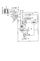
- FIG. 13 shows an electronic apparatus 1 according to a first modification of the first embodiment.
- a transistor 91 is provided instead of the relay 61.
- the transistor 91 is, for example, an FET type, but may be, for example, a bipolar type, and is not particularly limited.
- the transistor 91 is an example of a “switching element” and a “changing unit”. When the detection unit 52 applies a predetermined voltage to the hot line 35 via the power supply line 41, the first portion 42 a of the first line 42. And the grounding state 37 are changed.
- the control circuit 64 sends a control signal to the transistor 91 according to the output of the voltage monitoring circuit 63 to change the conduction state of the first line 42. That is, when it is determined that the AC power supply 32 is supplied, the control circuit 64 controls the transistor 91 so that the first line 42 is turned on. On the other hand, when it is determined that the AC power supply 32 is not supplied, the control circuit 64 controls the transistor 91 so that the first line 42 is turned off. Even with such a configuration, substantially the same function as that of the first embodiment described above can be realized.
- FIG. 14 shows an electronic device 1 according to a second modification of the first embodiment.
- a conduction state changing unit 93 is provided instead of the relay 61.
- the conduction state changing unit 93 is an example of a “switching element” and a “changing unit”, and can change the resistance value of the first line 42.
- the control circuit 64 sends a control signal to the conduction state changing unit 93 according to the output of the voltage monitoring circuit 63 to change the conduction state of the first line 42. That is, when it is determined that the AC power supply 32 is supplied, the control circuit 64 performs control so that the conduction state changing unit 93 is substantially free of resistance. On the other hand, when it is determined that the AC power supply 32 is not supplied, the control circuit 64 performs control so that the resistance of the conduction state changing unit 93 is set to the second state that is larger than the first state. Even with such a configuration, substantially the same function as that of the first embodiment described above can be realized.
- FIG. 15 shows an electronic device 1 according to a third modification of the first embodiment.
- the electronic device 1 includes another power storage unit 95 in addition to the battery 15.
- the power storage unit 95 is an example of a “third power source”.
- the power storage unit 95 has a smaller output voltage than the battery 15, for example.
- the power storage unit 95 may be a second battery provided inside the electronic device 1, but may be a capacitor, for example.
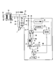
- (Fourth modification) 16 and 17 show an electronic apparatus 1 according to a fourth modification of the first embodiment.
- the electronic device 1 according to this modification includes a polarity switching unit 97.
- the polarity switching unit 97 is inserted in series in the middle of the first line 42 and in the middle of the second line 43, and connects the first and second lines 42, 43 and the first and second connection units 44, 45. Switch.
- FIG. 16 shows a case where the first connecting portion 44 is connected to the hot wire 35 and the second connecting portion 45 is connected to the ground wire 37.
- the polarity switching unit 97 connects (conducts) the first connection unit 44 and the first line 42 and connects (conducts) the second connection unit 45 and the second line 43.
- the wiring of the hot wire 35 and the ground wire 37 is reversed, and the first connection portion 44 is connected to the ground wire 37 and the second connection portion 45. May be connected to the hot line 35.
- the polarity switching unit 97 connects (conducts) the second connection unit 45 and the first line 42 and connects (conducts) the first connection unit 44 and the second line 43. The polarity of the first line 42 and the second line 43 is switched.
- the polarity switching unit 97 connects the first connection unit 44 and the first line 42, and connects the second connection unit 45 and the second line 43.
- the electronic device 1 is attached to, for example, a socket in a state where the switch 34 is turned off at normal times.
- the control circuit 64 receives a logic signal from the voltage monitoring circuit 63 and opens the relay 61 when there is no input of the first signal.
- the control circuit 64 receives a logic signal from the voltage monitoring circuit 63 with the relay 61 opened, and when the second signal is input, the first line 42 is connected to the hot line 35 and the first line 42 is connected. It is determined that the two lines 43 are connected to the ground wire 37, and the state of the polarity switching unit 97 is maintained as it is.
- the control circuit 64 connects the first line 42 to the ground line 37 and connects the second line 43 to the hot line 35.
- the polarity switching unit 97 is controlled, and the polarities of the first line 42 and the second line 43 are automatically switched.
- the control circuit 64 further receives a logic signal from the voltage monitoring circuit 63, and when the second signal is input, the first line 42 is connected to the hot line 35 and the second line 43 is connected to the ground line. 37, and the state of the polarity switching unit 97 is maintained as it is.
- the electronic apparatus 1 includes the polarity switching unit 97 that switches the power supply line 41 so that the first line 42 is connected to the hot line 35 and the second line 43 is connected to the ground line 37. Further prepare. According to such a configuration, the electronic device 1 can be used even when the wiring of the hot wire 35 and the ground wire 37 is reversed due to the configuration of the socket or the like. This further enhances the convenience of the electronic device 1.
- control unit 53 automatically switches the polarity switching unit 97 according to the voltage level applied to the power line 41. According to such a configuration, even when the wiring of the hot wire 35 and the ground wire 37 is reversed, the user is not required to perform a special operation. This further enhances the convenience of the electronic device 1.
- FIG. 18 shows an electronic apparatus 1 according to a fifth modification of the first embodiment.
- the detection unit 52 instead of monitoring the potential set on the first line 42, the detection unit 52 sends a predetermined signal to the first line 42 to monitor the reflection state of the wall switch 34. Detect state.
- the detection unit 52 includes a signal transmission unit 101 and a signal detection unit 102.
- the signal transmission unit 101 outputs a predetermined signal (inspection signal) to the first line 42.
- a predetermined signal inspection signal
- the signal flows to the hot line 35 without being reflected.
- the signal detection unit 102 since the signal detection unit 102 does not detect the reflection of the signal, it is determined that the wall switch 34 is in a conductive state.
- the wall switch 34 when the wall switch 34 is in a non-conductive state, the signal is reflected by the wall switch 34 and returns to the first line 42. In this case, when the signal detection unit 102 detects the reflected signal, the wall switch 34 is determined to be in a non-conduction state. Even with such a configuration, substantially the same function as that of the first embodiment described above can be realized.
- FIG. 19 shows an electronic apparatus 1 according to the second embodiment.
- the electronic device 1 of the present embodiment changes the light emission mode of the light emitting unit 13 so as to notify the user that, for example, it is in a power failure state.
- control unit 53 includes a drive circuit 105 (drive unit) that drives the light emitting unit 13.
- the control circuit 64 controls the power supply switching unit 49 so that power is supplied from the AC power supply 32 to the light emitting unit 13, and sets the light emitting unit 13 in the first mode (first mode).
- the drive circuit 105 is controlled to emit light in the single light emission mode (normal light emission mode, normal mode).
- the first mode is a normal lighting mode, for example, a mode in which the light emitting unit 13 continues to be lit as in a general light bulb.
- the control circuit 64 determines that the AC power supply 32 is not supplied, the control circuit 64 controls the power supply switching unit 49 so that power is supplied from the battery 15 to the light emitting unit 13, and the light emitting unit 13 is set to the second mode.
- the drive circuit 105 is controlled to emit light in (second light emission mode, power failure mode).
- the second mode is a mode for notifying the user that, for example, a power failure is occurring.
- This second mode includes, for example, an operation of blinking the light emitting unit 13 at least once.
- the second mode for example, when the power supply to the light emitting unit 13 is switched from the AC power supply 32 to the battery 15, the light emitting unit 13 may be blinked, or the light emitting unit 13 may be blinked every predetermined time.
- the second mode may be a lighting mode that suppresses power consumption compared to the first mode, for example.
- the second mode is a lighting mode in which the brightness is suppressed as compared with the first mode, for example. That is, the second mode may inform the user that the power is in a power failure state by reducing the brightness compared to the first mode.
- the drive circuit 105 may realize the second mode (flashing operation, light amount reduction, etc.) by controlling the light emitting unit 13, or may control the second mode (flashing) by controlling the power supply switching unit 49. Operation etc.) may be realized.
- the electronic device 1 of the present embodiment may further include a notification device 106 that informs the user that, for example, it is in a power failure state.
- the alarm device 106 may be a speaker that emits a sound when power supply to the light emitting unit 13 is switched from the AC power supply 32 to the battery 15, another light emitting unit that emits a different color, or the like.
- the control circuit 64 controls the drive circuit 105 so as to operate the alarm device 106 when, for example, the power supply to the light emitting unit 13 is switched from the AC power supply 32 to the battery 15.
- the convenience of the electronic device 1 can be further improved. That is, according to an electronic device that can be used without change during a normal time or during a power failure, it may be difficult for the user to notice that a power failure occurred. Therefore, in the present embodiment, the control unit 53 emits light in the first light emission mode when power is supplied from the AC power supply 32, and emits light in the second light emission mode when power is supplied from the second power supply. The light emitting unit 13 is controlled. According to such a configuration, the user can easily recognize that a power failure has occurred by viewing the light emission in the second light emission mode.
- the second light emission mode includes an operation of blinking the light emitting unit at least once. According to such a configuration, it becomes easier for the user to notice that a power failure has occurred. Thereby, the convenience of the electronic device 1 can be further improved.
- the electronic apparatus 1 of the present modification includes an adjustment unit 107 that can adjust the lighting state of the light emitting unit 13 in the second mode. More specifically, the adjustment unit 107 is, for example, a rotary knob exposed to the outside of the electronic device 1 and can be directly operated by the user. The adjustment unit 107 is provided on the outer peripheral surface of the globe connector 108 provided between the globe 11 and the base 12, for example.
- the electronic device 1 can change the lighting mode of the light emitting unit 13 by operating the adjusting unit 107.
- the user can adjust the brightness of lighting in the second mode by operating the adjustment unit 107, for example. That is, the user suppresses the brightness of the light emitting unit 13 while maintaining the battery 15 in comparison with the mode (first power mode) in which the light emitting unit 13 is lit brightly but the battery 15 is relatively short in duration.
- a mode with a relatively long time can be selected by itself.
- a plurality of the second power modes may be set in stages with respect to the first power mode, or may be set to be continuously variable in a stepless manner from the first power mode to a different brightness. Also good.
- the electronic device 1 since the user can adjust the duration of the battery 15 by itself, the electronic device 1 can be used effectively according to various situations. Thereby, the convenience of the electronic device 1 can be further improved.
- FIG. 22 shows an electronic apparatus 1 according to the third embodiment.
- the wall switch 34 is a double-cut type that blocks both the hot wire 35 and the ground wire 37.
- the relay 61 may be omitted as compared with the configuration of the first embodiment. Even with such a configuration, the convenience of the electronic device 1 can be improved as in the first embodiment.
- the electronic device 1 having the relay 61 can be used regardless of whether the wall switch 34 is a single-cut type or a double-cut type, so that it is highly versatile and should be used without worrying about the type of the wall switch 34. Because it is possible, it is highly convenient.
- FIG. 23 shows an electronic apparatus 1 according to the fourth embodiment.
- the electronic device 1 includes a light emitting unit 13 provided at a substantially central portion of the light bulb, and a spherical globe 11 that covers the light emitting unit 13.
- the electronic device 1 is, for example, an LED lamp, but instead of this, an incandescent bulb, a halogen lamp, an HID (High Intensity Discharge) lamp, a fluorescent lamp, or the like may be used. Even with such a configuration, the convenience of the electronic device 1 can be improved as in the first embodiment.
- FIG. 24 shows an electronic apparatus 1 according to the fifth embodiment.
- the electronic device 1 includes, for example, an elongated light emitting unit 13.
- the light emitting unit 13 is, for example, a fluorescent lamp, but may be a light emitting unit provided with a plurality of light emitting elements 13a such as LEDs instead.
- the power supply unit 14, the battery 15, and the control unit 16 are provided, for example, on the back of the ceiling. Even with such a configuration, the convenience of the electronic device 1 can be improved as in the first embodiment.
- FIG. 25 shows an electronic apparatus 1 according to the sixth embodiment.
- a breaker 111 is provided in the middle of the power supply line 31.
- the breaker 111 is an example of a switch provided outside the electronic device 1.
- the breaker 111 can be operated indoors, for example.
- the electronic device 1 is connected to a power supply line 31 that is switched between supply and interruption of the AC power supply 32 by the breaker 111.
- the electronic device 1 is connected to the power supply line 31 by being connected to, for example, an outlet provided indoors.
- the electronic device 1 according to the present embodiment detects whether or not the AC power supply 32 is supplied and the state of the breaker 111, and controls the power supplied to the load unit 112 (output unit).
- the electronic device 1 includes a determination unit 51, a detection unit 52, and a control unit 53.
- the determination unit 51 is electrically connected to the first line 42 and determines whether the AC power supply 32 is supplied.
- the detection unit 52 is electrically connected to the first line 42 and detects the conduction state of the breaker 111 in a state where the determination unit 51 determines that the AC power supply 32 is not supplied, for example.
- the control unit 53 Based on the outputs of the determination unit 51 and the detection unit 52, the control unit 53 either cuts at least the power supplied to the electronic device 1, is supplied from the AC power supply 32, or is supplied from the battery 15. To.
- the electronic device 1 operates as follows. [When the breaker 111 is in a conductive state under normal conditions] When the breaker 111 is in a conductive state at normal times, the voltage monitoring circuit 63 sends the first signal (toggle signal) to the control circuit 64 based on the AC power supply 32. The control circuit 64 determines that the AC power supply 32 is supplied by receiving the first signal, and controls the power supply switching unit 49 so that power is supplied from the AC power supply 32. Thereby, the electronic device 1 can operate by being supplied with electric power from the AC power supply 32.
- the breaker 111 may be automatically shut off due to an earthquake or the like.
- the second signal is input from the voltage monitoring circuit 63 to the control circuit 64. Based on the second signal, the control circuit 64 controls the power supply switching unit 49 so as to cut off the power supply to the electronic device 1.
- the control circuit 64 receives the third signal from the voltage monitoring circuit 63. Based on the third signal, the control circuit 64 controls the power supply switching unit 49 so that electric power is supplied from the battery 15 to the electronic device 1. As a result, the electronic device 1 can operate with power supplied from the battery 15.
- the electronic device 1 that can improve convenience. That is, according to such a configuration, it is possible to supply power from the battery 15 to the electronic device 1 by returning the breaker 111 even when the AC power supply 32 is not supplied at the time of a power failure. Thereby, the electronic device 1 useful in an emergency can be provided.
- each modification of the first embodiment may be applied as appropriate in the configurations of the second to sixth embodiments.
- the said embodiment and modification may be variously deformed and implemented individually.
- the “power supply system” includes, for example, a power supply line 31, a wall switch 34, and the electronic device 1.
Landscapes
- Business, Economics & Management (AREA)
- Emergency Management (AREA)
- Engineering & Computer Science (AREA)
- Power Engineering (AREA)
- Circuit Arrangement For Electric Light Sources In General (AREA)
- Stand-By Power Supply Arrangements (AREA)
Abstract
L'invention concerne un dispositif électronique qui peut basculer entre l'alimentation et la coupure d'un bloc d'alimentation en courant alternatif au moyen d'un commutateur externe au dispositif, et qui est pourvu d'une unité de détermination qui détermine si oui ou non le bloc d'alimentation en courant alternatif fournit de l'électricité, d'une unité de détection qui détecte l'état de conduction du commutateur, d'un second bloc d'alimentation qui est différent du bloc d'alimentation en courant alternatif, d'une unité de sortie, et d'une unité de commande. Sur la base du résultat de l'unité de détection et de l'unité de détermination, l'unité de commande, au moins, soit coupe l'alimentation fournie à l'unité de sortie, soit fournit ladite alimentation à partir du bloc d'alimentation en courant alternatif, soit fournit ladite alimentation à partir du second bloc d'alimentation.
Priority Applications (1)
| Application Number | Priority Date | Filing Date | Title |
|---|---|---|---|
| US15/266,488 US10091861B2 (en) | 2014-05-30 | 2016-09-15 | Electronic device |
Applications Claiming Priority (2)
| Application Number | Priority Date | Filing Date | Title |
|---|---|---|---|
| JP2014-113385 | 2014-05-30 | ||
| JP2014113385A JP5781196B1 (ja) | 2014-05-30 | 2014-05-30 | 電子機器 |
Related Child Applications (1)
| Application Number | Title | Priority Date | Filing Date |
|---|---|---|---|
| US15/266,488 Continuation US10091861B2 (en) | 2014-05-30 | 2016-09-15 | Electronic device |
Publications (1)
| Publication Number | Publication Date |
|---|---|
| WO2015182015A1 true WO2015182015A1 (fr) | 2015-12-03 |
Family
ID=54192826
Family Applications (1)
| Application Number | Title | Priority Date | Filing Date |
|---|---|---|---|
| PCT/JP2014/083572 Ceased WO2015182015A1 (fr) | 2014-05-30 | 2014-12-18 | Dispositif électronique |
Country Status (3)
| Country | Link |
|---|---|
| US (1) | US10091861B2 (fr) |
| JP (1) | JP5781196B1 (fr) |
| WO (1) | WO2015182015A1 (fr) |
Families Citing this family (7)
| Publication number | Priority date | Publication date | Assignee | Title |
|---|---|---|---|---|
| TWI611141B (zh) * | 2015-04-17 | 2018-01-11 | 中原大學 | 具電能管理功能之照明系統 |
| US10910873B2 (en) * | 2016-06-10 | 2021-02-02 | Asco Power Technologies, L.P. | Method of identifying when to initiate control sequences |
| JP7355971B2 (ja) * | 2018-08-21 | 2023-10-04 | 東西電工株式会社 | Mri室用電池内蔵型led非常用照明器具 |
| JP6868909B2 (ja) * | 2019-01-28 | 2021-05-12 | アクシオヘリックス株式会社 | 停電時電力供給装置及び照明装置 |
| JPWO2021084759A1 (fr) * | 2019-11-01 | 2021-05-06 | ||
| CN111683435A (zh) * | 2020-05-25 | 2020-09-18 | 中船邮轮科技发展有限公司 | 一种可实时通断控制的附加应急照明设备及舱室 |
| US12510213B1 (en) * | 2025-08-15 | 2025-12-30 | Zhenhong Li | LED light |
Citations (5)
| Publication number | Priority date | Publication date | Assignee | Title |
|---|---|---|---|---|
| JPH0378444A (ja) * | 1989-08-19 | 1991-04-03 | Mitsubishi Electric Corp | バッテリーバックアップ回路 |
| JPH0439088U (fr) * | 1990-07-26 | 1992-04-02 | ||
| JP2013125709A (ja) * | 2011-12-15 | 2013-06-24 | Canon Electronics Inc | 電子機器および制御装置 |
| JP2014082910A (ja) * | 2012-10-18 | 2014-05-08 | Advance Create Inc | 停電検出方法、停電検出器、照明装置、及び電源装置 |
| JP3193468U (ja) * | 2013-07-26 | 2014-10-02 | エターレクチュアル ビジネス カンパニー, リミテッド | 非常照明機能付き照明器具 |
Family Cites Families (19)
| Publication number | Priority date | Publication date | Assignee | Title |
|---|---|---|---|---|
| JPH0439088A (ja) | 1990-06-04 | 1992-02-10 | Mitsubishi Paper Mills Ltd | 感熱転写用受像紙 |
| US8491159B2 (en) * | 2006-03-28 | 2013-07-23 | Wireless Environment, Llc | Wireless emergency lighting system |
| US8994276B2 (en) * | 2006-03-28 | 2015-03-31 | Wireless Environment, Llc | Grid shifting system for a lighting circuit |
| EP2058922A1 (fr) | 2007-11-08 | 2009-05-13 | Ceramate Technical Co., Ltd | Unité de lampe intellectuelle capable d'être installée sur une douille de lampe conventionnelle contrôlée par un interrupteur mural |
| JP5094462B2 (ja) | 2008-02-21 | 2012-12-12 | 三菱電機株式会社 | 制御回路及び放電灯点灯装置及び照明器具 |
| JP2011119136A (ja) | 2009-12-03 | 2011-06-16 | Sharp Corp | Led照明装置 |
| JP2012164436A (ja) | 2011-02-03 | 2012-08-30 | Sekisui Chem Co Ltd | 照明器具 |
| GB2513221B (en) | 2011-03-31 | 2015-07-29 | Litonics Ltd | Lighting device |
| JP2013101785A (ja) | 2011-11-07 | 2013-05-23 | Sony Corp | 照明装置 |
| JP5670936B2 (ja) | 2012-02-27 | 2015-02-18 | 株式会社東芝 | 照明装置 |
| JP3177856U (ja) | 2012-04-10 | 2012-08-23 | ▲緑▼智能科技股▲ふん▼有限公司 | ウォールスイッチを利用しledランプグループをインテリジェントコントロール可能なデバイス |
| CN102685994B (zh) * | 2012-05-29 | 2014-05-14 | 耿波 | 应急灯电源装置 |
| JP2014002904A (ja) | 2012-06-18 | 2014-01-09 | Cyber Coin Kk | 蛍光灯型led照明装置およびその点消灯モード切替方法 |
| JP5993766B2 (ja) | 2013-03-26 | 2016-09-14 | 株式会社東芝 | 照明装置 |
| JP6235283B2 (ja) | 2013-09-24 | 2017-11-22 | 株式会社東芝 | 照明装置 |
| US9425649B2 (en) * | 2014-01-03 | 2016-08-23 | Capstone Lighting Technologies, Llc. | Apparatus and method for switch state detection and controlling electrical power |
| JP2015179579A (ja) | 2014-03-18 | 2015-10-08 | 株式会社東芝 | 導光体および照明装置 |
| JP2015179571A (ja) | 2014-03-18 | 2015-10-08 | 株式会社東芝 | 導光体および照明装置 |
| JP6453660B2 (ja) | 2015-02-05 | 2019-01-16 | 株式会社東芝 | 照明装置 |
-
2014
- 2014-05-30 JP JP2014113385A patent/JP5781196B1/ja active Active
- 2014-12-18 WO PCT/JP2014/083572 patent/WO2015182015A1/fr not_active Ceased
-
2016
- 2016-09-15 US US15/266,488 patent/US10091861B2/en active Active
Patent Citations (5)
| Publication number | Priority date | Publication date | Assignee | Title |
|---|---|---|---|---|
| JPH0378444A (ja) * | 1989-08-19 | 1991-04-03 | Mitsubishi Electric Corp | バッテリーバックアップ回路 |
| JPH0439088U (fr) * | 1990-07-26 | 1992-04-02 | ||
| JP2013125709A (ja) * | 2011-12-15 | 2013-06-24 | Canon Electronics Inc | 電子機器および制御装置 |
| JP2014082910A (ja) * | 2012-10-18 | 2014-05-08 | Advance Create Inc | 停電検出方法、停電検出器、照明装置、及び電源装置 |
| JP3193468U (ja) * | 2013-07-26 | 2014-10-02 | エターレクチュアル ビジネス カンパニー, リミテッド | 非常照明機能付き照明器具 |
Also Published As
| Publication number | Publication date |
|---|---|
| US20170006692A1 (en) | 2017-01-05 |
| JP5781196B1 (ja) | 2015-09-16 |
| JP2015228735A (ja) | 2015-12-17 |
| US10091861B2 (en) | 2018-10-02 |
Similar Documents
| Publication | Publication Date | Title |
|---|---|---|
| JP5781196B1 (ja) | 電子機器 | |
| CN102858051B (zh) | 照明装置 | |
| US9811985B2 (en) | Power outage safety light bulb | |
| JP4943402B2 (ja) | Led駆動回路、led照明灯具、led照明機器、及びled照明システム | |
| US11454361B2 (en) | Automatically adjusting task light | |
| US20100237798A1 (en) | Method and apparatus for retrofitting lighting fixtures with dimmable color selectable light emitting diodes | |
| US10681782B2 (en) | Dimmable universal voltage LED power supply with regenerating power source circuitry and non-isolated load | |
| JP5447969B2 (ja) | Led点灯装置およびled照明器具 | |
| CN102450105A (zh) | 照明装置 | |
| WO2012046569A1 (fr) | Dispositif d'alimentation électrique et dispositif d'éclairage | |
| JP6096842B2 (ja) | 電子機器 | |
| KR101265484B1 (ko) | 탈착형 led 조명 기구 | |
| EP2838318A1 (fr) | Circuit d'éclairage et luminaire | |
| US9591706B2 (en) | Universal voltage LED power supply with regenerating power source circuitry, non-isolated load, and 0-10V dimming circuit | |
| JP2012164436A (ja) | 照明器具 | |
| JP6114988B2 (ja) | 点灯装置および、これを用いた照明器具 | |
| JP2010182499A (ja) | 照明装置 | |
| JP2008243444A (ja) | 放電灯点灯装置及び照明器具 | |
| JP6572718B2 (ja) | 照明器具 | |
| JP2013030415A (ja) | センサ付き照明制御装置およびセンサ付き照明器具 | |
| KR101206469B1 (ko) | Led 조명장치 | |
| JP2009009741A (ja) | ライティングダクト装置 | |
| KR101209025B1 (ko) | Led 조명장치 | |
| KR102556080B1 (ko) | 취급 간편 엘이디 전등기구 조명장치 | |
| JP2015181124A (ja) | 照明装置 |
Legal Events
| Date | Code | Title | Description |
|---|---|---|---|
| 121 | Ep: the epo has been informed by wipo that ep was designated in this application |
Ref document number: 14893268 Country of ref document: EP Kind code of ref document: A1 |
|
| NENP | Non-entry into the national phase |
Ref country code: DE |
|
| 122 | Ep: pct application non-entry in european phase |
Ref document number: 14893268 Country of ref document: EP Kind code of ref document: A1 |