WO2015182109A1 - Dispositif de détection de niveau de liquide - Google Patents
Dispositif de détection de niveau de liquide Download PDFInfo
- Publication number
- WO2015182109A1 WO2015182109A1 PCT/JP2015/002631 JP2015002631W WO2015182109A1 WO 2015182109 A1 WO2015182109 A1 WO 2015182109A1 JP 2015002631 W JP2015002631 W JP 2015002631W WO 2015182109 A1 WO2015182109 A1 WO 2015182109A1
- Authority
- WO
- WIPO (PCT)
- Prior art keywords
- fitting
- outer cylinder
- distance
- inner shaft
- engaging portion
- Prior art date
- Legal status (The legal status is an assumption and is not a legal conclusion. Google has not performed a legal analysis and makes no representation as to the accuracy of the status listed.)
- Ceased
Links
Images


Classifications
-
- G—PHYSICS
- G01—MEASURING; TESTING
- G01F—MEASURING VOLUME, VOLUME FLOW, MASS FLOW OR LIQUID LEVEL; METERING BY VOLUME
- G01F23/00—Indicating or measuring liquid level or level of fluent solid material, e.g. indicating in terms of volume or indicating by means of an alarm
- G01F23/30—Indicating or measuring liquid level or level of fluent solid material, e.g. indicating in terms of volume or indicating by means of an alarm by floats
- G01F23/56—Indicating or measuring liquid level or level of fluent solid material, e.g. indicating in terms of volume or indicating by means of an alarm by floats using elements rigidly fixed to, and rectilinearly moving with, the floats as transmission elements
- G01F23/62—Indicating or measuring liquid level or level of fluent solid material, e.g. indicating in terms of volume or indicating by means of an alarm by floats using elements rigidly fixed to, and rectilinearly moving with, the floats as transmission elements using magnetically actuated indicating means
Definitions
- the present disclosure relates to a liquid level detection device that detects a liquid level of a liquid stored in a container.
- a liquid level detection device for detecting a liquid level of a liquid stored in a container.
- a body for example, a body (lid), an outer cylinder that covers a float that floats on the liquid level, and an inner shaft that houses a detection element that detects the position of the float are integrated. And a cover (housing) to be formed. And the opening part located in the upper end of a cover is liquid-tightly sealed with the body.
- the present inventor has examined a configuration in which an outer cylinder engaging portion provided in an elastically deformable manner is provided on the cover and a body engaging portion provided in an engageable manner with the outer cylinder engaging portion is provided in the body.
- a configuration in which an outer cylinder engaging portion provided in an elastically deformable manner is provided on the cover and a body engaging portion provided in an engageable manner with the outer cylinder engaging portion is provided in the body.
- the cover in the assembly process of the body and the cover, if the cover is inserted slightly diagonally, unintended elastic deformation occurs in the outer cylinder engaging portion, and there is a risk that the shaft cannot be smoothly fitted.
- the outer cylinder engaging portion may be damaged and the yield may be reduced. As a result, it has been difficult to smoothly provide a liquid level detection device that prevents dropout.
- the present disclosure has been made in view of the problems described above, and an object thereof is to provide a liquid level detection device that prevents dropout.
- the liquid level detection apparatus in a liquid level detection device that detects a liquid level of a liquid stored in a container, can be assembled to the container in a predetermined fitting direction.
- a body having a fitting peripheral wall that forms a peripheral wall surface along the inner periphery, a fitting hole provided on the inner peripheral side of the fitting peripheral wall, and a cover that is fitted to the body, and is fitted along the fitting direction.
- the third position for engaging with the body engaging portion is set, and the distance at which the outer cylinder is fitted with the fitting peripheral wall is defined as the outer cylinder fitting distance, and the inner shaft is fitted with the fitting hole.
- the distance between the first position and the third position is defined as the engagement distance
- at least one of the outer cylinder engagement distance and the inner shaft engagement distance is It is characterized by being larger than the combined distance.
- the cover when the cover is fitted to the body along a predetermined fitting direction, Prior to the contact between the tube engaging portion and the body engaging portion, at least one of the fitting between the outer tube and the fitting peripheral wall and the fitting between the inner shaft and the fitting hole is started. Then, with the fitting of the cover to the body, after the outer cylinder engaging portion comes into contact with the body engaging portion at the first position, the outer cylinder engaging portion is pressed by the body engaging portion at the second position. The outer cylinder engaging portion is then elastically restored and engaged with the body engaging portion at the third position.
- the outer tube engaging portion is elastically deformed, so that the assembly can be performed smoothly. Further, since the body and the cover are fitted on the inner peripheral side and the outer peripheral side, respectively, the holding force of the cover is increased and the vibration is restricted, so that the cover can be prevented from falling off the body. As described above, it is possible to provide a liquid level detection device that prevents dropping.
- the drawing It is a figure which shows the state in which the liquid level detection apparatus in 1st Embodiment was installed in the oil pan. It is sectional drawing which shows the main-body part in 1st Embodiment, Comprising: It is a figure which also shows the 3rd position in an assembly
- the liquid level detection device 100 As shown in FIG. 1, the liquid level detection device 100 according to the first embodiment is mounted on an internal combustion engine of a vehicle and installed in an oil pan 1 as a container. The oil pan 1 is attached to the bottom surface of a cylinder block of an internal combustion engine, and stores engine oil as a liquid. The liquid level detection device 100 detects the liquid level LL of the engine oil stored in the oil pan 1.
- the liquid level detection device 100 mainly includes a connector part 6, a main body part 10, and a wire 7.
- the connector portion 6 liquid-tightly closes the opening 1a provided on the side wall of the oil pan 1, and is a mating connector portion (not shown) for electrically connecting to an external vehicle-mounted device (for example, a combination meter). ) And can be fitted.
- the main body 10 is fixed to the oil pan 1 in the installed state of FIG.
- the main body 10 can detect the liquid level LL of the engine oil stored in the oil pan 1.
- the wire 7 electrically connects the connector portion 6 and the main body portion 10, and is disposed, for example, over the bracket 2.
- the liquid level detection device 100 can output the detection signal from the main body 10 to the outside via the wire 7 and the connector unit 6.
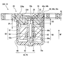
- the main body 10 of the liquid level detection device 100 includes a body 20, a cover 40, a float 50, and a reed switch 60 as a detection element.
- the bodies shown in FIGS. 2 and 3 are made of, for example, polyphenylene sulfide (PPS) resin.
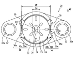
- the body 20 includes a body partition wall 22, a fitting peripheral wall 24, a fitting hole 26, a communication hole 28, a body engaging portion 30, and a flange portion 32.
- the body partition wall 22 is formed in a disc shape and partitions the storage chamber 12.
- a plurality of protruding body stoppers 23 are provided on the body partition wall 22 on the cover 40 side. Each body stopper 23 extends along the radial direction of the body partition wall 22.
- the body stoppers 23 are arranged at equal intervals (for example, 90 ° intervals) in the circumferential direction of the body partition wall 22.
- the fitting peripheral wall 24 is formed so as to surround the outer periphery of the disk-shaped body partition wall 22.
- the fitting peripheral wall 24 has a peripheral wall surface 24a on the outer periphery along a predetermined fitting direction WF.
- the fitting direction WF in the present embodiment is a disc-shaped thickness direction and is a direction from the cover 40 toward the body 20.
- the fitting hole 26 is provided on the cover 40 side at the center of the disc-shaped body partition wall 22 on the inner peripheral side of the fitting peripheral wall 24, and is cylindrical in the fitting direction WF with respect to the body partition wall 22. It is recessed.
- the communication hole 28 is provided through the fitting hole 26 and communicates with the oil pan 1 by being recessed in the fitting direction WF. That is, the body 20 is penetrated by the fitting hole 26 and the communication hole 28.
- a plurality of body engaging portions 30 are formed at intervals on the outer periphery of the body partition wall 22 so as to divide the fitting peripheral wall 24.
- four body engaging portions 30 are formed.
- Each body engaging portion 30 is provided with an engaging hole 30a penetrating in the fitting direction WF.
- a claw-like engagement projection 30b is provided inside each engagement hole 30a.
- the side surface of each engagement protrusion 30b is inclined with respect to the fitting direction WF, facing the fitting direction WF and facing the fitting surface 30c substantially perpendicular to the fitting direction WF, and facing the opposite direction to the fitting direction WF. It forms a slope 30d.
- the flange portion 32 is formed in a bowl shape on the outer peripheral side of the body partition wall 22 formed in a disc shape.
- An assembly ring 32a formed in a cylindrical shape with metal is embedded in the flange portion 32.
- the flange portion 32 of the body 20 can be assembled to the oil pan 1 by screwing the bracket 2 with the assembly ring 32a.
- the cover 40 is formed into a bottomed cylindrical shape as a whole by using, for example, PPS resin which is the same material as the body 20.
- the cover 40 integrally includes a bottom wall 42, an outer cylinder 44, and an inner shaft 46, and is fitted to the body 20 by the outer cylinder 44 and the inner shaft 46.
- the bottom wall 42 is disposed in a direction opposite to the mating direction WF in the cover 40 and is formed in a disc shape.
- the outer cylinder 44 protrudes from the outer peripheral part of the bottom wall 42 along the fitting direction WF, and is formed in a cylindrical shape.
- the outer cylinder 44 is fitted into the fitting peripheral wall 24 in a press-fit state along the fitting direction WF.
- the outer cylinder 44 has outer cylinder engaging portions 44 a provided at four locations corresponding to the body engaging portions 30 in the circumferential direction.
- Each outer cylinder engaging portion 44a is provided so as to be elastically deformable, and forms an engaging claw 44b.
- Each engagement claw 44b is further extended in the fitting direction WF from the tip of the outer cylinder 44 so that it can be inserted into each engagement hole 30a. In this way, each outer cylinder engaging portion 44a and each body engaging portion 30 are engaged.
- the inner shaft 46 protrudes along the fitting direction WF from the inner peripheral portion of the bottom wall 42 on the inner peripheral side of the outer cylinder 44 and is formed in a cylindrical shape.
- the inner shaft 46 is fitted in the fitting hole 26 along the fitting direction WF.
- cover stoppers 43 are provided on the bottom wall 42 on the body 20 side. Each cover stopper 43 extends radially from the inner shaft 46 toward the outer cylinder 44. The cover stoppers 43 are arranged at equal intervals (for example, 60 ° intervals) in the circumferential direction of the bottom wall 42.
- the float 50 has a foam 52 and a magnet 54, and can float on the liquid level of the engine oil.
- the foam 52 is formed in a cylindrical shape with a material having a specific gravity smaller than that of engine oil such as foamed phenol resin.
- An annular holding groove 52 a is formed on the inner peripheral side of the foam 52.
- the magnet 54 is a permanent magnet such as ferrite and is formed in a cylindrical shape. The magnet 54 is held in the foam 52 by being fitted in the holding groove 52 a of the foam 52.
- the float 50 having such a configuration is disposed between the outer cylinder 44 and the inner shaft 46 by being inserted through the inner shaft 46 of the cover 40, and follows the liquid level LL and is guided to the inner shaft 46. While being done, it reciprocates along the direction opposite to the fitting direction WF and the fitting direction WF.
- the float 50 is restricted from moving toward the body 20 by contact with the body stopper 23, and is restricted from moving toward the cover 40 by contact with the cover stopper 43.
- the reed switch 60 is a detection element that detects the position of the float 50 that moves along the fitting direction WF.
- the reed switch 60 has a glass tube 62 formed in a cylindrical shape, and a pair of leads 64a-b extending from both ends of the glass tube 62.
- the reed switch 60 is inserted into the inner shaft 46 in a posture in which the axial direction of the glass tube 62 is aligned with the fitting direction WF, and is disposed over the fitting hole 26 and the communication hole 28.
- the glass tube 62 is a hollow cylindrical glass tube, and each end portion (hereinafter referred to as a lead end portion) of each lead 64a-b is liquid-tightly accommodated.
- Each lead end portion is provided so as to be able to bend, and faces each other with a predetermined interval.
- each lead end attracts each other by being magnetized to different magnetic poles.
- the respective lead end portions come into contact with each other, and the reed switch 60 is turned on so as to be conductive between the respective leads 64a and 64b.
- the lead ends do not contact each other, and the reed switch 60 is turned off.
- Terminals 70a and 70b are formed in a strip shape from a conductive material such as brass.
- the terminals 70a and 70b are held in the body 20 by being insert-molded in the body 20.
- One terminal 70 a is accommodated in the inner shaft 46 and extends to a position closer to the bottom wall 42 than the glass tube 62.
- the terminal 70a is connected to one lead 64a and supports the lead 64a.
- the other terminal 70b is connected to the other lead 64b in the vicinity of the fitting hole 26, and supports the lead 64b.
- the reed switch 60 is held with respect to the body 20 by being attached to each terminal 70a-b.
- the float 50 When the liquid level detection device 100 is installed in the oil pan 1 in this way, the float 50 is fitted to the reed switch 60 inserted in the inner shaft 46 when the engine oil liquid level LL is sufficiently high. It is moving in the direction WF. In this case, since the magnet 54 is close to the reed switch 60, the reed switch 60 is turned on. On the other hand, when the engine oil decreases, the float 50 moves in the direction opposite to the fitting direction WF with respect to the reed switch 60 inserted in the inner shaft 46. In this case, since the magnet 54 is separated from the reed switch 60, the reed switch 60 is turned off. That is, the liquid level detecting device 100 can detect the level LL of the engine oil stored in the oil pan 1 by detecting the position of the float 50 where the reed switch 60 moves along the fitting direction WF. It becomes possible.
- the assembly process of the body 20 and the cover 40 will be described as a method of manufacturing the liquid level detection device 100 according to the first embodiment with reference to FIGS.
- the lead switch 60 is attached in advance to the terminals 70a and 70b by welding and heat caulking on the body 20 before the assembly process. Further, the float 50 is inserted into the inner shaft 46 in the cover 40 before the assembly process. However, in FIGS. 5 to 7, the reed switch 60, the terminals 70a and 70b, and the float 50 are omitted.
- the side of the body 20 on which the fitting peripheral wall 24 and the fitting hole 26 are formed is opposed to the side of the cover 40 on which the tip of the outer cylinder 44 and the tip of the inner shaft 46 are formed. Then, the cover 40 is assembled to the body 20 along the fitting direction WF.
- the tip of the inner shaft 46 of the cover 40 reaches the opening of the fitting hole 26 (the position of the cover 40 is set to the initial position). P0).
- the outer diameter DS at the tip of the inner shaft 46 is substantially the same as the diameter DH of the fitting hole 26, the inner shaft 46 is fitted into the fitting hole 26 along the fitting direction WF.
- the cover 40 is guided by the fitting so as to be assembled in a direction along the fitting direction WF.
- the engaging claws 44b of the outer cylinder engaging portion 44a are not in contact with the engaging protrusions 30b of the body engaging portion 30 and are in a free state.
- the outer cylinder engaging portion 44 a is connected to the body engaging portion 30. Contact. More specifically, the engaging claw 44b of the outer cylinder engaging portion 44a comes into contact with the engaging protrusion 30b of the body engaging portion 30 at the inclined surface 30d (the position of the cover 40 is set to the first position P1). ).
- the end of the outer cylinder 44 reaches the fitting peripheral wall 24 (not shown).
- the inner diameter DP at the tip of the outer cylinder 44 is formed smaller than the outer diameter DW of the fitting peripheral wall 24 by, for example, about 0.2 to 0.5 mm. Therefore, by pressing the cover 40 in the fitting direction WF, the outer cylinder 44 is deformed to the outer peripheral side and starts fitting to the fitting peripheral wall 24 in the press-fitted state.
- the outer cylinder engaging portion 44 a is pressed by the body engaging portion 30 with the fitting of the cover 40 to the body 20. Elastically deforms. More specifically, the engaging claw 44b of the outer cylinder engaging portion 44a is pressed along the inclined surface 30d of the engaging protrusion 30b of the body engaging portion 30 and is elastically deformed to the inner peripheral side (this cover).
- the position 40 is set as the second position P2.
- the outer cylinder engaging portion 44 a is elastically restored and the body engaging portion 30.
- Engage with More specifically, the engaging claw 44b of the outer cylinder engaging portion 44a gets over the engaging protrusion 30b of the body engaging portion 30 and wraps around the back of the engaging surface 30c, so that the engaging claw 44b and the engaging protrusion 30b (The position of the cover 40 is set as the third position P3).
- the tip of the inner shaft 46 stops at the boundary between the fitting hole 26 and the communication hole 28 at the third position P3.
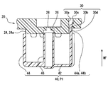
- the distance at which the outer cylinder 44 is fitted to the fitting peripheral wall 24 is defined as an outer cylinder fitting distance SP.
- the outer cylinder fitting distance SP corresponds to a distance along the fitting direction WF between the tip of the outer cylinder 44 and the end of the peripheral wall surface 24a, as shown in FIG.
- the distance at which the inner shaft 46 is fitted to the fitting hole 26 is defined as an inner shaft fitting distance SS.
- the inner shaft fitting distance SS corresponds to a distance along the fitting direction WF between the tip of the inner shaft 46 and the opening of the fitting hole 26 as shown in FIG.
- the distance between the first position P1 indicated by a two-dot chain line in FIG. 2 and the third position P3 indicated by a solid line in FIG. 2 is defined as an engagement distance SE.
- the engagement distances SE corresponding to the body engaging portions 30 and the outer cylinder engaging portions 44a are set to be substantially the same.
- At least one of the outer cylinder fitting distance SP and the inner shaft fitting distance SS is set to be larger than the engagement distance SE. More specifically, the inner shaft fitting distance SS is the largest, the engagement distance SE is the next largest, and the outer cylinder fitting distance SP is the smallest.
- the inner shaft 46 corresponding to the largest inner shaft fitting distance SS is first fitted into the fitting hole 26, and the outer cylinder corresponding to the outer cylinder fitting distance SP is started.
- the fitting of the cylinder 44 to the fitting peripheral wall 24 is started, and the contact between the outer cylinder engaging portion 44a and the body engaging portion 30 corresponding to the engaging distance SE is thereafter.
- the cover 40 is attached to the body 20 in a predetermined fitting direction.
- the outer tube 44 and the fitting peripheral wall 24 are fitted and the inner shaft 46 and the fitting hole 26 before the contact between the outer tube engaging portion 44a and the body engaging portion 30.
- At least one of the fittings is started.
- the outer cylinder engaging portion 44a contacts the body engaging portion 30 at the first position P1, and then the outer cylinder engaging portion 44a is moved to the body at the second position P2.
- the outer cylinder engaging part 44a is elastically restored and engaged with the body engaging part 30 at the third position P3 after being pressed and elastically deformed by the engaging part 30. According to this, after the cover 40 is guided so as to be assembled along the fitting direction WF, the outer cylinder engaging portion 44a is elastically deformed, so that the assembly can be performed smoothly. Further, since the body 20 and the cover 40 are fitted on the inner peripheral side and the outer peripheral side, respectively, the holding force of the cover 40 is increased and the vibration is restricted, so that the cover 40 can be prevented from falling off the body 20. As described above, it is possible to provide the liquid level detection device 100 that prevents the dropout.
- the body 20 has the communication hole 28 that can communicate with the oil pan 1 through the fitting hole 26.
- the inner shaft 46 is fitted into the fitting hole 26 that communicates with the communication hole 28, air can be released through the communication hole 28, so that the inner shaft 46 can be firmly fitted. As a result, dropout can be prevented.
- the second embodiment is a modification of the first embodiment.
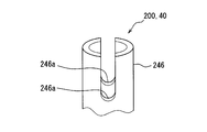
- the inner shaft 246 in the liquid level detection device 200 of the second embodiment projects along the fitting direction WF from the inner peripheral portion of the bottom wall 42 on the inner peripheral side of the outer cylinder 44, as in the first embodiment. It is formed in a cylindrical shape.
- the tip of the inner shaft 246 has a window 246a that allows deformation of the tip. More specifically, as shown in FIG. 8, two U-shaped notched windows 246 a are provided at the tip of the inner shaft 246 at positions facing each other.
- the inner shaft 246 is fitted into the fitting hole 26 along the fitting direction WF in a press-fitted state.
- the tip of the inner shaft 246 reaches the opening of the fitting hole 26 (the position of the cover 40 is initially set). Set as position P0).
- the outer diameter DS at the tip of the inner shaft 246 is formed to be larger than the diameter DH of the fitting hole 26 by, for example, about 0.2 to 0.5 mm. Therefore, by pressing the cover 40 in the fitting direction WF, the distal end of the inner shaft 246 that is allowed to be deformed by the window 246a is deformed to the inner peripheral side, and the fitting to the fitting peripheral wall 24 in the press-fitted state is performed. Start.
- the cover 40 is guided by this fitting so as to be assembled in a direction along the fitting direction WF.
- the engaging claw 44b of the outer cylinder engaging portion 44a is not in contact with the engaging protrusion 30b of the body engaging portion 30, and is in a free state.
- At least one of the outer cylinder fitting distance SP and the inner shaft fitting distance SS is set to be larger than the engagement distance SE. Therefore, it is possible to achieve the operational effects according to the first embodiment.
- the tip of the inner shaft 246 fitted into the fitting hole 26 in the press-fitted state has the window 246a that allows deformation of the tip. According to this, even if it is the front-end
- the third embodiment is a modification of the first embodiment.
- the fitting peripheral wall 324 in the liquid level detection device 300 of the third embodiment protrudes in the direction opposite to the fitting direction WF with respect to the body partition wall 22.
- the fitting peripheral wall 324 has a peripheral wall surface 324a on the outer periphery along the fitting direction WF including the protruding range.
- the outer cylinder fitting distance SP and the inner shaft fitting distance SS are set to be larger than the engagement distance SE.
- the outer cylinder fitting distance SP is the largest
- the inner shaft fitting distance SS is the second largest
- the engagement distance SE is the smallest.
- the tip of the outer cylinder 44 reaches the fitting peripheral wall 324 (the position of the cover 40 is set to the initial position P0). And set).
- the inner diameter DP at the tip of the outer cylinder 44 is formed smaller than the outer diameter DW of the fitting peripheral wall 324 by, for example, about 0.2 to 0.5 mm. Therefore, by pressing the cover 40 in the fitting direction WF, the outer cylinder 44 is deformed to the outer peripheral side and starts fitting to the fitting peripheral wall 324 in the press-fitted state. And the cover 40 is guided by this fitting so that it may be assembled
- the engaging claws 44b of the outer cylinder engaging portion 44a are not in contact with the engaging protrusions 30b of the body engaging portion 30 and are in a free state.
- the tip of the inner shaft 46 of the cover 40 reaches the opening of the fitting hole 26, and the inner shaft 46 is fitted in the fitting hole 26 as in the first embodiment. Fitted.
- At least one of the outer cylinder fitting distance SP and the inner shaft fitting distance SS is set to be larger than the engagement distance SE. Therefore, it is possible to achieve the operational effects according to the first embodiment.
- the fitting peripheral wall 324 protrudes in the direction opposite to the fitting direction WF. According to this, since the outer cylinder fitting distance SP can be set as long as possible, it is easy to make the outer cylinder fitting distance SP larger than the engagement distance SE. As a result, dropout can be prevented.
- an element other than the reed switch 60 may be used.
- the Hall element may be used as a detection element after some processing for liquid resistance is performed.
- the magnitude of these distances may be other orders.
- the inner shaft fitting distance SS is the largest
- the outer cylinder fitting distance SP is the next largest
- the engagement distance SE may be set the smallest
- the outer cylinder fitting distance SP is the largest.
- the engagement distance SE may be set to be the largest
- the inner shaft fitting distance SS may be set to be the smallest.
- the body 20 may not have the communication hole 28 that can communicate with the oil pan 1.
- the outer diameter DS of the tip of the inner shaft 46 is formed larger than the diameter DH of the fitting hole 26, so that the inner shaft 46 is press-fit and the fitting hole 26 is
- the inner diameter DP at the tip of the outer cylinder 44 is substantially the same as the outer diameter DW of the fitting peripheral wall 24 so that the outer cylinder 44 is completely fitted to the fitting peripheral wall 24. May be.
- the fitting peripheral wall 24 may have a peripheral wall surface 24a on the inner periphery. Further, the outer cylinder 44 may be deformed to the inner peripheral side and fitted with the fitting peripheral wall 24 in a press-fitted state.
- the application target of the present disclosure is not limited to the detection of the engine oil liquid level LL.
- the present disclosure can be applied to a liquid level detection device in a container for other liquids mounted on the vehicle, such as brake fluid, engine coolant, and fuel.
- the present disclosure is applicable not only to vehicles but also to liquid level detection devices in containers provided in various consumer devices and various transport machines.
Landscapes
- Physics & Mathematics (AREA)
- Fluid Mechanics (AREA)
- General Physics & Mathematics (AREA)
- Level Indicators Using A Float (AREA)
Abstract
Selon la présente invention, une première position (P1) où une partie de mise en prise de cylindre externe (44a) vient en contact avec une partie de mise en prise de corps (30) conjointement avec le montage d'un couvercle (40) sur un corps (20), une deuxième position (P2) où la partie de mise en prise de cylindre externe (44a) est pressée par la partie de mise en prise de corps (30) et subit une déformation élastique, et une troisième position (P3) où le partie de mise en prise de cylindre extérieur (44a) subit une reprise élastique et vient en prise avec la partie de mise en prise de corps (30), sont établies. Si la longueur de la partie où le cylindre externe (44) est monté sur une paroi périphérique de montage (24, 324) est appelée une distance de montage de cylindre externe (SP), la longueur de la partie où un arbre interne (46, 246) est montée dans un trou de montage (26) est définie comme une distance de montage d'arbre interne (SS), et la distance entre la première position (P1) et la troisième position (P3) est appelée une distance de mise en prise (SE), alors la distance de montage de cylindre extérieur (SP) et/ou la distance de montage d'arbre interne (SS) est plus grande que la distance de mise en prise (SE).
Applications Claiming Priority (2)
| Application Number | Priority Date | Filing Date | Title |
|---|---|---|---|
| JP2014-109381 | 2014-05-27 | ||
| JP2014109381A JP2015224937A (ja) | 2014-05-27 | 2014-05-27 | 液面検出装置 |
Publications (1)
| Publication Number | Publication Date |
|---|---|
| WO2015182109A1 true WO2015182109A1 (fr) | 2015-12-03 |
Family
ID=54698459
Family Applications (1)
| Application Number | Title | Priority Date | Filing Date |
|---|---|---|---|
| PCT/JP2015/002631 Ceased WO2015182109A1 (fr) | 2014-05-27 | 2015-05-25 | Dispositif de détection de niveau de liquide |
Country Status (2)
| Country | Link |
|---|---|
| JP (1) | JP2015224937A (fr) |
| WO (1) | WO2015182109A1 (fr) |
Citations (7)
| Publication number | Priority date | Publication date | Assignee | Title |
|---|---|---|---|---|
| JPS63214621A (ja) * | 1987-03-02 | 1988-09-07 | Nissan Motor Co Ltd | 燃料タンクの液位計測装置 |
| JPH0293725U (fr) * | 1989-01-13 | 1990-07-25 | ||
| JPH02103235U (fr) * | 1989-02-03 | 1990-08-16 | ||
| JPH11316151A (ja) * | 1998-04-30 | 1999-11-16 | Kansei Corp | リードスイッチ式位置センサ |
| JP2000011828A (ja) * | 1998-06-25 | 2000-01-14 | Kansei Corp | リードスイッチ式位置センサ |
| JP2002071431A (ja) * | 2000-08-31 | 2002-03-08 | Nippon Seiki Co Ltd | 液面センサ |
| JP2002071430A (ja) * | 2000-08-31 | 2002-03-08 | Nippon Seiki Co Ltd | 液面検出装置 |
-
2014
- 2014-05-27 JP JP2014109381A patent/JP2015224937A/ja active Pending
-
2015
- 2015-05-25 WO PCT/JP2015/002631 patent/WO2015182109A1/fr not_active Ceased
Patent Citations (7)
| Publication number | Priority date | Publication date | Assignee | Title |
|---|---|---|---|---|
| JPS63214621A (ja) * | 1987-03-02 | 1988-09-07 | Nissan Motor Co Ltd | 燃料タンクの液位計測装置 |
| JPH0293725U (fr) * | 1989-01-13 | 1990-07-25 | ||
| JPH02103235U (fr) * | 1989-02-03 | 1990-08-16 | ||
| JPH11316151A (ja) * | 1998-04-30 | 1999-11-16 | Kansei Corp | リードスイッチ式位置センサ |
| JP2000011828A (ja) * | 1998-06-25 | 2000-01-14 | Kansei Corp | リードスイッチ式位置センサ |
| JP2002071431A (ja) * | 2000-08-31 | 2002-03-08 | Nippon Seiki Co Ltd | 液面センサ |
| JP2002071430A (ja) * | 2000-08-31 | 2002-03-08 | Nippon Seiki Co Ltd | 液面検出装置 |
Also Published As
| Publication number | Publication date |
|---|---|
| JP2015224937A (ja) | 2015-12-14 |
Similar Documents
| Publication | Publication Date | Title |
|---|---|---|
| JP5179295B2 (ja) | 温度センサの取付装置 | |
| CN109974922B (zh) | 用于测量流体的物理参数的装置 | |
| CN104124563A (zh) | 连接器 | |
| US10451512B2 (en) | Oil pressure sensor attachment structure | |
| JP6020360B2 (ja) | 液面検出装置 | |
| US10648878B2 (en) | Oil pressure sensor attachment structure | |
| KR102445584B1 (ko) | 초음파 변환기 | |
| US10197432B2 (en) | Liquid level sensor that adapts to pressure changes | |
| JP4089522B2 (ja) | 液面検出装置 | |
| EP1600780B1 (fr) | Capteur de rotation | |
| CN113494648A (zh) | 配有压力传感器的流体连接器 | |
| JP4568309B2 (ja) | 車載用圧力センサ及び車両用ブレーキ液圧制御装置 | |
| WO2015182109A1 (fr) | Dispositif de détection de niveau de liquide | |
| CN105264343B (zh) | 液面检测装置 | |
| JP2012151029A (ja) | 中継コネクタ | |
| JP2019165620A (ja) | 電気モータのためのクロージャーシステム及び対応する密閉方法 | |
| CN105409067A (zh) | 防液连接器 | |
| JP6626979B2 (ja) | 磁気センサ | |
| US20190178369A1 (en) | Contactless inhibitor switch | |
| JP6365508B2 (ja) | 液面検出装置 | |
| US9381898B2 (en) | Actuator for brake fluid pressure control | |
| JP4254715B2 (ja) | 液面検出装置 | |
| US20250003807A1 (en) | Sensor component | |
| JP2019028042A (ja) | 磁気センサ | |
| JP2016142550A (ja) | 液面検出装置 |
Legal Events
| Date | Code | Title | Description |
|---|---|---|---|
| 121 | Ep: the epo has been informed by wipo that ep was designated in this application |
Ref document number: 15799927 Country of ref document: EP Kind code of ref document: A1 |
|
| NENP | Non-entry into the national phase |
Ref country code: DE |
|
| 122 | Ep: pct application non-entry in european phase |
Ref document number: 15799927 Country of ref document: EP Kind code of ref document: A1 |