WO2015182151A1 - 空気入りタイヤ - Google Patents
空気入りタイヤ Download PDFInfo
- Publication number
- WO2015182151A1 WO2015182151A1 PCT/JP2015/002709 JP2015002709W WO2015182151A1 WO 2015182151 A1 WO2015182151 A1 WO 2015182151A1 JP 2015002709 W JP2015002709 W JP 2015002709W WO 2015182151 A1 WO2015182151 A1 WO 2015182151A1
- Authority
- WO
- WIPO (PCT)
- Prior art keywords
- sipe
- tread
- circumferential
- tire
- width direction
- Prior art date
- Legal status (The legal status is an assumption and is not a legal conclusion. Google has not performed a legal analysis and makes no representation as to the accuracy of the status listed.)
- Ceased
Links
Images



Classifications
-
- B—PERFORMING OPERATIONS; TRANSPORTING
- B60—VEHICLES IN GENERAL
- B60C—VEHICLE TYRES; TYRE INFLATION; TYRE CHANGING; CONNECTING VALVES TO INFLATABLE ELASTIC BODIES IN GENERAL; DEVICES OR ARRANGEMENTS RELATED TO TYRES
- B60C11/00—Tyre tread bands; Tread patterns; Anti-skid inserts
- B60C11/03—Tread patterns
- B60C11/0304—Asymmetric patterns
-
- B—PERFORMING OPERATIONS; TRANSPORTING
- B60—VEHICLES IN GENERAL
- B60C—VEHICLE TYRES; TYRE INFLATION; TYRE CHANGING; CONNECTING VALVES TO INFLATABLE ELASTIC BODIES IN GENERAL; DEVICES OR ARRANGEMENTS RELATED TO TYRES
- B60C11/00—Tyre tread bands; Tread patterns; Anti-skid inserts
- B60C11/01—Shape of the shoulders between tread and sidewall, e.g. rounded, stepped or cantilevered
-
- B—PERFORMING OPERATIONS; TRANSPORTING
- B60—VEHICLES IN GENERAL
- B60C—VEHICLE TYRES; TYRE INFLATION; TYRE CHANGING; CONNECTING VALVES TO INFLATABLE ELASTIC BODIES IN GENERAL; DEVICES OR ARRANGEMENTS RELATED TO TYRES
- B60C11/00—Tyre tread bands; Tread patterns; Anti-skid inserts
- B60C11/03—Tread patterns
- B60C11/0306—Patterns comprising block rows or discontinuous ribs
-
- B—PERFORMING OPERATIONS; TRANSPORTING
- B60—VEHICLES IN GENERAL
- B60C—VEHICLE TYRES; TYRE INFLATION; TYRE CHANGING; CONNECTING VALVES TO INFLATABLE ELASTIC BODIES IN GENERAL; DEVICES OR ARRANGEMENTS RELATED TO TYRES
- B60C11/00—Tyre tread bands; Tread patterns; Anti-skid inserts
- B60C11/03—Tread patterns
- B60C11/12—Tread patterns characterised by the use of narrow slits or incisions, e.g. sipes
-
- B—PERFORMING OPERATIONS; TRANSPORTING
- B60—VEHICLES IN GENERAL
- B60C—VEHICLE TYRES; TYRE INFLATION; TYRE CHANGING; CONNECTING VALVES TO INFLATABLE ELASTIC BODIES IN GENERAL; DEVICES OR ARRANGEMENTS RELATED TO TYRES
- B60C11/00—Tyre tread bands; Tread patterns; Anti-skid inserts
- B60C11/03—Tread patterns
- B60C11/12—Tread patterns characterised by the use of narrow slits or incisions, e.g. sipes
- B60C11/1236—Tread patterns characterised by the use of narrow slits or incisions, e.g. sipes with special arrangements in the tread pattern
-
- B—PERFORMING OPERATIONS; TRANSPORTING
- B60—VEHICLES IN GENERAL
- B60C—VEHICLE TYRES; TYRE INFLATION; TYRE CHANGING; CONNECTING VALVES TO INFLATABLE ELASTIC BODIES IN GENERAL; DEVICES OR ARRANGEMENTS RELATED TO TYRES
- B60C11/00—Tyre tread bands; Tread patterns; Anti-skid inserts
- B60C11/03—Tread patterns
- B60C11/12—Tread patterns characterised by the use of narrow slits or incisions, e.g. sipes
- B60C11/1259—Depth of the sipe
-
- B—PERFORMING OPERATIONS; TRANSPORTING
- B60—VEHICLES IN GENERAL
- B60C—VEHICLE TYRES; TYRE INFLATION; TYRE CHANGING; CONNECTING VALVES TO INFLATABLE ELASTIC BODIES IN GENERAL; DEVICES OR ARRANGEMENTS RELATED TO TYRES
- B60C11/00—Tyre tread bands; Tread patterns; Anti-skid inserts
- B60C11/03—Tread patterns
- B60C11/13—Tread patterns characterised by the groove cross-section, e.g. for buttressing or preventing stone-trapping
-
- B—PERFORMING OPERATIONS; TRANSPORTING
- B60—VEHICLES IN GENERAL
- B60C—VEHICLE TYRES; TYRE INFLATION; TYRE CHANGING; CONNECTING VALVES TO INFLATABLE ELASTIC BODIES IN GENERAL; DEVICES OR ARRANGEMENTS RELATED TO TYRES
- B60C17/00—Tyres characterised by means enabling restricted operation in damaged or deflated condition; Accessories therefor
- B60C17/0009—Tyres characterised by means enabling restricted operation in damaged or deflated condition; Accessories therefor comprising sidewall rubber inserts, e.g. crescent shaped inserts
-
- B—PERFORMING OPERATIONS; TRANSPORTING
- B60—VEHICLES IN GENERAL
- B60C—VEHICLE TYRES; TYRE INFLATION; TYRE CHANGING; CONNECTING VALVES TO INFLATABLE ELASTIC BODIES IN GENERAL; DEVICES OR ARRANGEMENTS RELATED TO TYRES
- B60C11/00—Tyre tread bands; Tread patterns; Anti-skid inserts
- B60C11/03—Tread patterns
-
- B—PERFORMING OPERATIONS; TRANSPORTING
- B60—VEHICLES IN GENERAL
- B60C—VEHICLE TYRES; TYRE INFLATION; TYRE CHANGING; CONNECTING VALVES TO INFLATABLE ELASTIC BODIES IN GENERAL; DEVICES OR ARRANGEMENTS RELATED TO TYRES
- B60C11/00—Tyre tread bands; Tread patterns; Anti-skid inserts
- B60C11/03—Tread patterns
- B60C2011/0337—Tread patterns characterised by particular design features of the pattern
- B60C2011/0339—Grooves
- B60C2011/0341—Circumferential grooves
- B60C2011/0355—Circumferential grooves characterised by depth
-
- B—PERFORMING OPERATIONS; TRANSPORTING
- B60—VEHICLES IN GENERAL
- B60C—VEHICLE TYRES; TYRE INFLATION; TYRE CHANGING; CONNECTING VALVES TO INFLATABLE ELASTIC BODIES IN GENERAL; DEVICES OR ARRANGEMENTS RELATED TO TYRES
- B60C11/00—Tyre tread bands; Tread patterns; Anti-skid inserts
- B60C11/03—Tread patterns
- B60C2011/0337—Tread patterns characterised by particular design features of the pattern
- B60C2011/0339—Grooves
- B60C2011/0358—Lateral grooves, i.e. having an angle of 45 to 90 degees to the equatorial plane
- B60C2011/036—Narrow grooves, i.e. having a width of less than 3 mm
-
- B—PERFORMING OPERATIONS; TRANSPORTING
- B60—VEHICLES IN GENERAL
- B60C—VEHICLE TYRES; TYRE INFLATION; TYRE CHANGING; CONNECTING VALVES TO INFLATABLE ELASTIC BODIES IN GENERAL; DEVICES OR ARRANGEMENTS RELATED TO TYRES
- B60C11/00—Tyre tread bands; Tread patterns; Anti-skid inserts
- B60C11/03—Tread patterns
- B60C11/12—Tread patterns characterised by the use of narrow slits or incisions, e.g. sipes
- B60C11/1204—Tread patterns characterised by the use of narrow slits or incisions, e.g. sipes with special shape of the sipe
- B60C2011/1209—Tread patterns characterised by the use of narrow slits or incisions, e.g. sipes with special shape of the sipe straight at the tread surface
-
- B—PERFORMING OPERATIONS; TRANSPORTING
- B60—VEHICLES IN GENERAL
- B60C—VEHICLE TYRES; TYRE INFLATION; TYRE CHANGING; CONNECTING VALVES TO INFLATABLE ELASTIC BODIES IN GENERAL; DEVICES OR ARRANGEMENTS RELATED TO TYRES
- B60C11/00—Tyre tread bands; Tread patterns; Anti-skid inserts
- B60C11/03—Tread patterns
- B60C11/12—Tread patterns characterised by the use of narrow slits or incisions, e.g. sipes
- B60C11/1236—Tread patterns characterised by the use of narrow slits or incisions, e.g. sipes with special arrangements in the tread pattern
- B60C2011/1245—Tread patterns characterised by the use of narrow slits or incisions, e.g. sipes with special arrangements in the tread pattern being arranged in crossing relation, e.g. sipe mesh
-
- B—PERFORMING OPERATIONS; TRANSPORTING
- B60—VEHICLES IN GENERAL
- B60C—VEHICLE TYRES; TYRE INFLATION; TYRE CHANGING; CONNECTING VALVES TO INFLATABLE ELASTIC BODIES IN GENERAL; DEVICES OR ARRANGEMENTS RELATED TO TYRES
- B60C11/00—Tyre tread bands; Tread patterns; Anti-skid inserts
- B60C11/03—Tread patterns
- B60C11/12—Tread patterns characterised by the use of narrow slits or incisions, e.g. sipes
- B60C11/1236—Tread patterns characterised by the use of narrow slits or incisions, e.g. sipes with special arrangements in the tread pattern
- B60C2011/1254—Tread patterns characterised by the use of narrow slits or incisions, e.g. sipes with special arrangements in the tread pattern with closed sipe, i.e. not extending to a groove
-
- B—PERFORMING OPERATIONS; TRANSPORTING
- B60—VEHICLES IN GENERAL
- B60C—VEHICLE TYRES; TYRE INFLATION; TYRE CHANGING; CONNECTING VALVES TO INFLATABLE ELASTIC BODIES IN GENERAL; DEVICES OR ARRANGEMENTS RELATED TO TYRES
- B60C11/00—Tyre tread bands; Tread patterns; Anti-skid inserts
- B60C11/03—Tread patterns
- B60C11/12—Tread patterns characterised by the use of narrow slits or incisions, e.g. sipes
- B60C11/1259—Depth of the sipe
- B60C2011/1268—Depth of the sipe being different from sipe to sipe
-
- B—PERFORMING OPERATIONS; TRANSPORTING
- B60—VEHICLES IN GENERAL
- B60C—VEHICLE TYRES; TYRE INFLATION; TYRE CHANGING; CONNECTING VALVES TO INFLATABLE ELASTIC BODIES IN GENERAL; DEVICES OR ARRANGEMENTS RELATED TO TYRES
- B60C11/00—Tyre tread bands; Tread patterns; Anti-skid inserts
- B60C11/03—Tread patterns
- B60C11/13—Tread patterns characterised by the groove cross-section, e.g. for buttressing or preventing stone-trapping
- B60C11/1353—Tread patterns characterised by the groove cross-section, e.g. for buttressing or preventing stone-trapping with special features of the groove bottom
- B60C2011/1361—Tread patterns characterised by the groove cross-section, e.g. for buttressing or preventing stone-trapping with special features of the groove bottom with protrusions extending from the groove bottom
-
- B—PERFORMING OPERATIONS; TRANSPORTING
- B60—VEHICLES IN GENERAL
- B60C—VEHICLE TYRES; TYRE INFLATION; TYRE CHANGING; CONNECTING VALVES TO INFLATABLE ELASTIC BODIES IN GENERAL; DEVICES OR ARRANGEMENTS RELATED TO TYRES
- B60C17/00—Tyres characterised by means enabling restricted operation in damaged or deflated condition; Accessories therefor
- B60C17/0009—Tyres characterised by means enabling restricted operation in damaged or deflated condition; Accessories therefor comprising sidewall rubber inserts, e.g. crescent shaped inserts
- B60C2017/0054—Physical properties or dimensions of the inserts
Definitions
- the present invention relates to a pneumatic tire.
- an object of the present invention is to provide a pneumatic tire that can achieve both steering stability and performance on snow.
- the gist configuration of the present invention is as follows.
- the pneumatic tire of the present invention has, on the tread surface, a width direction outermost land portion defined by an outermost circumferential main groove extending in the tread circumferential direction closest to the tread end and the tread end, and the width direction outermost land portion.
- the outer land portion has a plurality of side sipes extending outward in the tread width direction at intervals in the tread circumferential direction, and the outermost land portion in the width direction includes an inner circumferential sipe extending in the tread circumferential direction, An outer circumferential sipe located in the tread width direction outside the circumferential sipe and extending in the tread circumferential direction, the groove depth of the outermost circumferential main groove is h1, and the sipe depth of the inner circumferential sipe is h2, when the sipe depth of the outer circumferential sipe is h3, h1>h3> h2 It is characterized by satisfying.
- the “circumferential main groove” means that a pneumatic tire is mounted on an applied rim, filled with a specified internal pressure, and has a width of 2 mm or more opened to the tread tread when in a no-load state.
- “Sipe” is a thin notch that is cut from the surface of the land to the inside and can be closed when touched down. A pneumatic tire is attached to the applicable rim and the specified internal pressure is set. The width that opens to the tread surface when filled and unloaded is less than 2 mm.
- groove depth” and “sipe depth” refer to the average depth.
- “applicable rim” is an industrial standard that is effective in the region where tires are produced and used.
- JATMA Joint Automobile Tire Association
- ETRTO European Tire and Rim Technical
- Organization STANDARD MANUAL
- TRA TIRE and RIM ASSOCATION INC.
- the “specified internal pressure” refers to an internal pressure (maximum air pressure) corresponding to the tire maximum load capacity of the standard such as JATMA in a tire of an applicable size.
- FIG. 1 It is an expanded view which shows the tread pattern of the pneumatic tire concerning one Embodiment of this invention. It is a fragmentary perspective view of the pneumatic tire concerning another embodiment of the present invention. It is a partial expanded view which shows the principal part of the tread pattern shown in FIG. It is a tread circumferential direction sectional view of a lateral circumferential sipe and an outer circumferential sipe. It is a schematic plan view showing an example of a belt structure. It is a schematic plan view which shows the other example of a belt structure. It is a schematic plan view which shows another example of a belt structure. It is a tire width direction sectional view of the tire concerning one embodiment of the present invention in case the tire of the present invention is a run flat tire.
- FIG. 1 is a development view showing a tread pattern of a pneumatic tire (hereinafter also referred to as a tire) according to an embodiment of the present invention, in which the tire is mounted on an applied rim, filled with a specified internal pressure, The tread surface and buttress portion of the tire when developed are shown.
- a tire etc. since it is the same as that of the past, description is abbreviate
- the cross-sectional width SW of the tire is less than 165 (mm).
- the ratio SW / OD of the tire cross-sectional width SW to the outer diameter OD is 0.26 or less, and when the tire cross-sectional width SW is 165 (mm) or more, the tire cross-sectional width SW and outer diameter OD satisfies the relational expression, OD ⁇ 2.135 ⁇ SW + 282.3 (hereinafter also referred to as relational expression (1)).
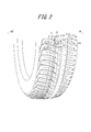
- 2 is a partial perspective view of a tire having a tread pattern similar to that of FIG. 1 except for the number of second one end opening sipes 15 and intermediate sipes 16 to be described later.
- the tire of the present embodiment has a circumferential main groove 2 that extends continuously in the tread circumferential direction on the tread surface 1.
- the tire has three circumferential main grooves 2a, 2b, and 2c on the tread tread 1, and the circumferential main groove 2a is one half of the tread centered on the tire equatorial plane CL.
- the circumferential main grooves 2b and 2c are arranged in the other half of the tread centering on the tire equatorial plane CL.
- these land direction main grooves 2a, 2b, 2c and the tread end TE define four land portions 3a, 3b, 3c, 3d in the illustrated example.
- the “tread end TE” here refers to the tread width direction of the ground contact surface when the tire is mounted on the applicable rim, the specified internal pressure is filled, and a load corresponding to the maximum load capacity (maximum load load) is applied. It shall be the outermost position.
- the groove width of the circumferential main groove 2a can be, for example, 7 to 10 mm
- the groove width of the circumferential main groove 2b can be, for example, 5 to 8 mm
- the circumferential main groove 2c The groove width can be, for example, 2 to 5 mm.
- the groove depth of the circumferential main groove 2a can be 6 to 8 mm, for example, and the groove depth of the circumferential main groove 2b can be 6 to 8 mm, for example.
- the groove depth of 2c can be 6 to 8 mm, for example.
- “groove width” and “groove depth” the opening width to the tread surface of the groove and the average depth of the groove when the tire is mounted on the applicable rim, the specified internal pressure is filled, and no load is applied. The same applies to other grooves and sipes.
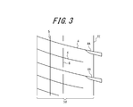
- FIG. 3 is a partial development view showing a main part of the tread pattern shown in FIG.
- the outermost circumferential main groove 2c extending in the circumferential direction of the tread closest to the tread end TE and the outermost land portion 3d in the width direction defined by the tread end TE are circumferential circumferential main grooves.
- a plurality of first side sipes 4 (14 in the range shown in FIG. 1) extending from 2c to the outside in the tread width direction are provided.
- the first side sipe 4 extends from the circumferential main groove 2 c outward in the tread width direction and communicates directly with the tread end TE.
- the first side sipe 4 is connected to the lug groove 4A located in the region outside the tread width TE from the tread end TE in the region outside the tread width TE and connected to the lug groove 4A. Things are alternately arranged in the tread circumferential direction.
- the tire of the present embodiment has one inner circumferential sipe 5 that extends continuously in the tread circumferential direction on the land portion 3d.
- the tire according to the present embodiment has a tread edge TE of the first side sipe 4 on the outer side in the tread width direction of the inner circumferential sipe 5 in the land portion 3d.
- One outer circumferential sipe 6 extending in the tread circumferential direction is provided between the two first side sipes 4 connected to the lug grooves 4A in the outer region in the tread width direction.
- the groove depth h1 of the circumferential main groove 2c, the sipe depth h2 of the inner circumferential sipe 5, and the sipe depth h3 of the outer circumferential sipe 6 are h1> h3. > H2 is satisfied.
- the effect of this embodiment is demonstrated.
- the following description of the function and effect is a description of the function and effect when the tire is mounted on the vehicle so that the land portion 3d is on the vehicle mounting inner side.
- the edge component in the straight traveling direction is ensured, and the performance on snow (snow traction performance and snow braking performance) when traveling straight. Can be improved.
- the land portion 3d has the inner circumferential sipe 5 and the outer circumferential sipe 6, the edge component with respect to the lateral force direction is also secured, and the performance on snow (snow cornering performance) during turning is improved. Can do. And the following effects can be obtained by satisfying h1>h3> h2. That is, it is preferable that the circumferential main groove 2c has a certain depth from the viewpoint of drainage.
- the sipe depth of the inner circumferential sipe 5 is made too deep under this premise, the rigidity of the land portion between the circumferential main groove 2c and the inner circumferential sipe 5 is too lowered, and the steering stability is lowered. .
- the sipe depth of the inner circumferential sipe 5 is shallower than the groove depth of the circumferential main groove 2c to ensure steering stability.
- the sipe depth of the outer circumferential sipe 6 is shallow, the circumferential sipe disappears at an early stage during wear, and the performance on snow at the time of wear deteriorates at a stretch.
- the sipe depth h3 of the outer circumferential sipe 6 is made deeper than the sipe depth h2 of the inner circumferential sipe 5.
- the sipe depth h2 of the inner circumferential sipe 5 is set shallow, even if the sipe depth h3 of the outer circumferential sipe 6 is deeper than h2, the land portion between the circumferential sipe 5, 6 The rigidity does not decrease too much.
- the circumferential sipes 5, 6 have less contribution to drainage than the circumferential main groove 2c, and the sipes of the circumferential sipes 5, 6 from the viewpoint of not reducing the rigidity of the land portion too much.
- the depths h2 and h3 are both shallower than the groove depth h1 of the circumferential main groove 2c.
- the outer circumferential sipe 6 is the first lateral sipe 4 that is not connected to the lug groove 4A in the outer region in the tread width direction of the first lateral sipe 4. Although intersecting, it does not communicate with the first side sipe 4 connected to the lug groove 4A in the outer region in the tread width direction. For this reason, steering stability and noise performance can be ensured without excessively reducing the rigidity of the block. For this reason, the outer circumferential sipe 6 is preferably separated from the first side sipe 4 connected to the lug groove 4A by 1.5 mm or more in the outer region in the tread width direction.
- the sipe width of the first side sipe 4 can be set to 0.5 to 1.5 mm, for example, and the sipe depth can be set to 6 to 8 mm, for example.
- the pitch interval in the tread circumferential direction of the first side sipe 4 is preferably 17 to 30 mm. By setting it to 17 mm or more, the rigidity of the land portion can be ensured, and steering stability and noise performance can be ensured. On the other hand, by setting it to 30 mm or less, the above-mentioned effect on improving the performance on snow can be achieved. This is because it can be obtained more effectively.
- the inclination angle of the sipe 4 is preferably set to 30 ° or less in order to improve the above-mentioned performance on snow during straight traveling.
- the sipe width of the inner circumferential sipe 5 can be set to 0.5 to 1.5 mm, for example, and the sipe depth can be set to 2 to 4 mm, for example.
- the sipe width of the outer circumferential sipe 6 may be 0.5 to 1.5 mm, for example, and the sipe depth may be 6 to 8 mm, for example.
- both end portions of the outer circumferential sipe 6 have a shape in which the side walls are inclined so that the circumferential length decreases from the tread tread surface 1 side toward the sipe depth direction.
- the sipe length can be secured in order to secure the edge component, while the corner portion of the sipe bottom is made obtuse and the rigidity is increased, and this corner portion becomes the wear nucleus. Therefore, it is possible to improve wear resistance.
- the inner circumferential sipe 5 extends continuously in the tread circumferential direction, and the outer circumferential sipe 6 has a terminal portion in the land portion 3d.
- the corner portion of the inner circumferential sipe 5 has a shallow sipe depth and is not easily deformed. Therefore, it is preferable to increase the edge component continuously in the tread circumferential direction, while the outer circumferential sipe 6 has a sipe depth. This is because the corner portion is easily deformed because the depth is relatively deep, and therefore the end portion has the rigidity of the corner portion so that the edge pressure can be secured. Thereby, the performance on snow at the time of turning can be improved as a whole.
- the bottom raised portion 7 can be, for example, 30 to 60% of the depth of the circumferential main groove 2c. Moreover, it is preferable to provide the bottom raising part 7 in the position where the 1st side sipe 4 communicates from a viewpoint which reinforces the part to which rigidity falls. In the embodiment shown in FIG.
- the ratio SW / OD of the tire cross-sectional width SW to the outer diameter OD Is 0.26 or less, and when the tire cross-sectional width SW is 165 (mm) or more, the tire cross-sectional width SW and the outer diameter OD satisfy the relational expression OD ⁇ 2.135 ⁇ SW + 282.3. Since it is a narrow tire that fills, even if the bottom raised portion 7 is provided, the wet performance can be sufficiently ensured.
- the pitch interval in the tread circumferential direction of the first side sipe 4 is L (mm)
- the distance in the tread width direction between the circumferential main groove 2c and the inner circumferential sipe 5 is W1 (mm).
- W2 the distance in the tread width direction between the inner circumferential sipe 5 and the outer circumferential sipe 6
- 0.7 ⁇ L / W1 ⁇ 1.4 and 0.7 ⁇ L / W1 ⁇ 1.4 It is preferable to satisfy. This is because by making the ratio L / W1 and the ratio L / W2 close to 1, the torsional rigidity of the land section defined by the sipe is increased, and the on-snow performance during turning can be further improved.
- the land portion 3a has a plurality of lateral lateral grooves 8 extending from the circumferential main groove 2a outward in the tread width direction (seven in the range shown in FIG. 1).
- the lateral lateral groove 8 extends outward in the tread width direction and communicates with the tread end TE.
- a second side that extends in the tread width direction and communicates with the tread end TE and the circumferential main groove 2a in the illustrated example. It has a sipe 9.
- the groove width of the lateral lateral groove 8 can be set to 2 to 4 mm, for example, and the groove depth can be set to 6 to 8 mm.
- the pitch interval in the tread circumferential direction of the two lateral lateral grooves 8 adjacent in the tread circumferential direction can be set to 17 to 30 mm.
- a straight line connecting the inner end of the lateral lateral groove 8 (in communication with the circumferential main groove 2a) in the tread width direction and the inner part of the lateral lateral groove 8 along the periphery of the lateral lateral groove 8 is formed.
- the inclination angle is 10 ° or more.
- the sipe width of the second side sipe 9 can be set to 0.5 to 1.5 mm, for example, and the sipe depth can be set to 6 to 8 mm.
- the inclination angle of the sipe 9 is preferably 40 ° or less. This is because, when the angle is 40 ° or less, the above-mentioned performance on snow during straight traveling can be effectively obtained.
- the tire of this embodiment has one side circumferential sipe 10 extending in the tread circumferential direction between each of the two lateral lateral grooves 8 adjacent in the tread circumferential direction. .
- both ends of the side circumferential sipe 10 are terminated in the land portion 3 a and do not communicate with the side lateral grooves 8.
- this lateral circumferential sipe 10 an edge component in the lateral force direction can be ensured particularly in a vehicle-mounted outer land portion having a great influence on steering stability, and the performance on snow during turning can be further improved. .
- the pitch interval of the lateral lateral grooves 8 in the tread circumferential direction is set to 17 to 30 mm, the width of the block in the tread circumferential direction is large.
- the shape of the block is divided into two blocks (strictly speaking, the side circumferential sipe 10 is not completely divided because it does not communicate with the side lateral grooves 8), so that the shape of the block is square.
- the side circumferential sipe 10 intersects with the second side sipe 9 but does not communicate with the lateral lateral groove 8, so that the steering stability and noise performance can be improved without excessively reducing the rigidity of the block. Can be secured. For this reason, it is preferable that the side circumferential sipe 10 is separated from the side main groove 8 by 1.5 mm or more.
- the sipe width of the side circumferential sipe 10 may be 0.5 to 1.5 mm, for example, and the sipe depth may be 6 to 8 mm, for example.
- both end portions of the side circumferential sipe 10 have a shape in which the side walls are inclined so that the circumferential length decreases from the tread tread surface 1 side toward the sipe depth direction. .
- the sipe length can be secured in order to secure the edge component.
- the corner portion of the sipe bottom is used as an obtuse angle to increase rigidity, and this corner portion becomes a wear nucleus. The wear resistance can be improved.
- a bottom raised portion 11 is provided in the side main groove 8.
- the rigidity of a block can be improved, steering stability and abrasion resistance can be improved, and a steering sound can be reduced further.
- the bottom raised portion 11 can have a height of 30 to 60% of the groove depth of the lateral lateral groove 8, for example.
- the ratio SW / OD of the tire cross-sectional width SW to the outer diameter OD Is 0.26 or less, and when the tire cross-sectional width SW is 165 (mm) or more, the tire cross-sectional width SW and the outer diameter OD satisfy the relational expression OD ⁇ 2.135 ⁇ SW + 282.3. Since it is a narrow tire that fills, even if the bottom raised portion 11 is provided, sufficient wet performance can be ensured.
- the land portion 3b partitioned by the circumferential main groove 2a and the circumferential main groove 2b is a tread width extending between the circumferential main grooves 2a and 2b. It is a rib-like land portion having no groove extending in the direction. And this land part 3b has one circumferential direction sipe 12 by the example of illustration extended continuously in the tread circumferential direction.
- the sipe width of the circumferential sipe 12 can be set to 0.5 to 1.5 mm, for example, and the sipe depth of the circumferential sipe 12 can be set to 3 to 6 mm, for example.
- the rib-shaped land portion 3b extends from the circumferential main groove 2a to the inner side in the tread width direction to a position communicating with the circumferential sipe 12, and terminates in the rib-shaped land portion 3b.
- a plurality of (four in the range shown in FIG. 1) one-end opening lateral grooves 13 are provided.
- the rib-like land portion 3b extends in the tread width direction from the circumferential main groove 2b and ends in the rib-like land portion 3b without communicating with the circumferential narrow groove 4 (the range shown in FIG. 1). 15) first end opening sipes 14.
- the groove width (maximum width) of the one-end opening lateral groove 13 can be set to 3 to 5 mm, for example, and the groove depth can be set to 6 to 8 mm.
- the sipe width of the first one-end opening sipe 14 can be set to 0.5 to 1.5 mm, for example, and the sipe depth can be set to 2 to 4 mm.
- “one-end open lateral groove” and “one-end open sipe” mean that one end opens in the circumferential main groove and the other end does not open in the circumferential main groove or lateral groove, but the other end is in the circumferential direction. Including those communicating with narrow grooves and sipes.
- the rigidity in the vicinity of the circumferential main groove 2a is greatly affected by input from the road surface during cornering.
- the tread rubber may be deformed by the compressive stress on the vehicle mounting outer side and the tensile stress on the vehicle mounting inner side, and the belt may be deformed to cause a buckling phenomenon in which the ground contact surface is lifted.
- the one end opening lateral groove 13 is provided, the one end opening lateral groove 13 is closed by a compressive stress on the outside of the vehicle, so that the tread rubber or the belt is not deformed. Can be suppressed. Furthermore, since the one-end opening lateral groove 13 terminates in the rib-like land portion 3b, rigidity against tensile stress inside the vehicle is increased, thereby suppressing deformation of the tread and the belt. Therefore, according to this embodiment, the occurrence of buckling can be suppressed first.
- the tire of this embodiment has the circumferential sipe 12
- an edge component with respect to the lateral force direction can be secured, and the performance on snow during turning can be improved.
- the corner portion of the block is formed in the land portion 3b by the communication between the circumferential sipe 12 and the lateral groove 13 at the one end opening, the edge effect in the straight traveling direction and the lateral force direction is increased, and the straight traveling is performed. It is possible to improve the snow performance at the time of turning and the snow performance at the time of turning.
- the first end opening sipe 14 is provided, the edge component in the straight traveling direction can be further increased, and the performance on snow during straight traveling can be improved.
- the rigidity of the rib-like land portion 3b is not excessively lowered, and the steering stability and noise performance can be ensured. . Therefore, it is possible to make the steering stability, the noise performance, and the performance on snow more compatible.
- a plurality of one-end opening lateral grooves 13 are formed in the rib-like land portion 3 b at intervals in the tread circumferential direction, but the rib-like land portions 3 b are arranged between the one-end opening lateral grooves 13.
- One or more (10 in the range shown in FIG. 1) extending from the circumferential main groove 2a to the inner side in the tread width direction to a position communicating with the circumferential sipe 12 and terminating in the rib-like land portion 3b.
- a second end opening sipe 15 is provided. In the illustrated example, three second one end opening sipes 15 are provided between two one end opening lateral grooves 13 adjacent to each other in the tread circumferential direction.
- the sipe width of the second one-end opening sipe 15 can be set to 0.5 to 1.5 mm, for example, and the sipe depth can be set to 6 to 8 mm.
- the sipe width of the second one-end opening sipe 15 can be set to 0.5 to 1.5 mm, for example, and the sipe depth can be set to 6 to 8 mm.
- the pitch interval in the tread circumferential direction of the two one-end opening lateral grooves 13 adjacent in the tread circumferential direction is preferably 35 to 70 mm.
- the pitch interval in the tread circumferential direction of the first one end opening sipe 14 is preferably 10 to 15 mm. By setting it to 10 mm or more, the rigidity of the land portion can be ensured, and the steering stability and noise performance can be ensured.
- the pitch interval in the tread circumferential direction of the second one end opening sipe 15 is preferably 10 to 15 mm.
- the pitch interval in the tread circumferential direction of the second one end opening sipe 15 is preferably 10 to 15 mm.
- the 1st one end opening sipe 14 crosses tire equatorial plane CL (it extends beyond tire equatorial plane CL).
- the first one-end opening sipe 14 is disposed at this position, thereby effectively improving the performance on snow during straight traveling. Because you can. Further, in this case, since the one-end opening lateral groove 13 is located outside when the tire is mounted, it becomes easy to obtain the buckling suppressing effect as described above.
- the inclination angle of the one-end opening lateral groove 5 is 30. It is preferable that the angle is not more than °. This is because the effect of suppressing buckling described above can be obtained more effectively by setting the angle to 30 ° or less. Further, when the angle formed by the straight line connecting both ends of the first one end opening sipe 14 with respect to the tread width direction is the inclination angle with respect to the tread width direction of the first one end opening sipe 14, the first one end opening.
- the inclination angle of the sipe 14 is preferably 35 ° or less.
- the angle formed by the straight line connecting both ends of the second one end opening sipe 15 with respect to the tread width direction is the inclination angle of the second one end opening sipe 15 with respect to the tread width direction
- the first one end opening The inclination angle of the sipe 15 is preferably 40 ° or less. This is because, when the angle is 40 ° or less, the above-mentioned performance on snow during straight traveling can be effectively obtained.
- a plurality of intermediate sipes 16 extending from the circumferential main groove 2c to the inner side in the tread width direction and terminating in the land portion 3c are formed in the land portion 3c (see FIG. 1). 14) within the range shown in FIG.
- the land portion 3c is formed with a portion that becomes a rib-like land portion continuous in the tread circumferential direction.
- the intermediate sipe 16 can secure an edge component in the straight traveling direction, and can further improve the performance on snow during straight traveling.
- the sipe width of the intermediate sipe 16 can be set to 0.5 to 1.5 mm, for example, and the sipe depth can be set to 6 to 8 mm, for example.
- the pitch interval in the tread circumferential direction of the intermediate sipe 16 is preferably 10 to 15 mm. By setting it to 10 mm or more, the rigidity of the land portion can be ensured, and the steering stability and noise performance can be ensured. On the other hand, by setting it to 15 mm or less, the above-mentioned effect on improving the performance on snow during straight traveling can be achieved. This is because it can be obtained more effectively.
- the inclination angle of the intermediate sipe 16 is 15 ° or more. It is preferable. This is because it is possible to ensure not only the traveling direction but also the edge components of both the traveling direction and the lateral force direction, so that the performance on snow during straight traveling and turning can be comprehensively improved.
- the extension length of the intermediate sipe 16 in the tread width direction is preferably 40 to 80% of the width of the land portion 3c in the tread width direction. By setting it to 40% or more, it is possible to sufficiently secure the edge component and further improve the performance on the snow when going straight. On the other hand, by setting it to 80% or less, a rib-shaped land portion having a sufficient width can be obtained. It is because it can form and can improve riding comfort.
- a tire with a small number of lateral grooves and a large number of sipes especially when the internal pressure is 250 kPa or more and the tire cross-sectional width SW is less than 165 (mm)
- the ratio SW / OD between the cross-sectional width SW and the outer diameter OD is 0.26 or less, and when the tire cross-sectional width SW is 165 (mm) or more, the cross-sectional width SW and the outer diameter OD of the tire are It is suitable for a tire having a narrow width and a large diameter satisfying the relational expression, OD ⁇ 2.135 ⁇ SW + 282.3, and further suitable for a tire having a ratio OD / SW of 3.6 or more.
- the tire of the present invention is preferably used at an internal pressure of 250 to 350 kPa, particularly suitable for use under a high internal pressure of 280 kPa or higher, and used at a high internal pressure of 300 kPa or higher. Further preferred. In the condition of narrow width and high internal pressure, the wet performance can be sufficiently secured, so the number of lateral grooves can be reduced, and instead the number of sipes can be increased, so at high internal pressure This is because the edge effect can be effectively exhibited in combination with the large force that the sipe bites the road surface depending on the use conditions. Further, the tire is suitable as a radial tire for passenger cars, and preferably has an air volume of 15000 cm 3 or more in order to cope with a load that can be used on public roads.
- the tire size of the tire of the present invention is 105 / 50R16, 115 / 50R17, 125 / 55R20, 125 / 60R18, 125 / 65R19, 135 / 45R21, 135 / 55R20, 135 / 60R17, 135 / 60R18.
- the pneumatic radial tire for passenger cars of the present invention satisfying the relational expression (1), it is preferable to use a high elastic rubber for the tread rubber from the viewpoint of improving the wet performance.
- a pneumatic radial tire for a passenger car having a narrow width and a large diameter that satisfies the above relational expression (1) has a narrow ground contact width and a high ground contact pressure particularly when high internal pressure is used, so that the circumferential shear rigidity is increased. This is considered to improve the ground contact on the wet road surface.
- the high elastic rubber preferably has a dynamic storage elastic modulus E ′ at 30 ° C.
- the wet performance can be further improved in the pneumatic radial tire for passenger cars having a narrow width and a large diameter.
- the loss tangent tan ⁇ at 60 ° C. of the tread rubber is preferably 0.05 to 0.15. By satisfying this range, the rolling resistance can be further reduced.
- the tread rubber may be formed by laminating a plurality of different rubber layers in the tire radial direction.
- the plurality of rubber layers those having different tangent loss, modulus, hardness, glass transition temperature, material and the like can be used.
- the ratio of the thickness in the tire radial direction of the plurality of rubber layers may be changed in the tire width direction, or only the circumferential main groove bottom or the like may be a rubber layer different from the periphery thereof.
- the tread rubber may be formed of a plurality of rubber layers different in the tire width direction.
- the plurality of rubber layers those having different tangent loss, modulus, hardness, glass transition temperature, material and the like can be used.
- the ratio of the width of the plurality of rubber layers in the tire width direction may be changed in the tire radial direction, and only in the vicinity of the circumferential main groove, only in the vicinity of the tread end TE, only in the shoulder land portion, only in the center land portion. Only a limited part of the area can be a rubber layer different from the surrounding area.
- the tire of the present invention preferably has an inclined belt layer composed of a rubberized layer of cords extending incline with respect to the tire circumferential direction.
- the inclined belt layer may be only one layer.
- the inclined belt layer extends in the direction in which the cords cross each other.
- a belt structure in which two belt layers form an inclined belt layer is most preferable.
- the width in the tire width direction of the maximum width inclined belt layer having the largest width in the tire width direction is preferably 90% to 115% of the tread width TW, and is 100% to 105% of the tread width TW. It is particularly preferred.
- a metal cord particularly a steel cord is most commonly used as the belt cord of the inclined belt layer, but an organic fiber cord can also be used.
- the steel cord is mainly composed of steel and can contain various trace contents such as carbon, manganese, silicon, phosphorus, sulfur, copper, and chromium.
- a monofilament cord or a cord obtained by twisting a plurality of filaments can be used as the belt cord of the inclined belt layer.
- Various designs can be adopted for the twist structure, and various cross-sectional structures, twist pitches, twist directions, and distances between adjacent filaments can be used.
- the cord which twisted the filament of a different material can also be used, and it does not specifically limit as a cross-sectional structure, Various twisted structures, such as a single twist, a layer twist, a double twist, can be taken.
- the inclination angle of the belt cord of the inclined belt layer is preferably 10 ° or more with respect to the tire circumferential direction.
- the inclination angle of the belt cord of the inclined belt layer is preferably set to a high angle, specifically 35 ° or more with respect to the tire circumferential direction, and particularly within a range of 55 ° to 85 ° with respect to the tire circumferential direction. .
- This is because by setting the inclination angle to 35 ° or more, the rigidity in the tire width direction can be increased, and in particular, the steering stability performance during cornering can be improved.
- the rolling resistance performance can be improved by reducing the shear deformation of the interlayer rubber.
- the tire of the present invention can have a circumferential belt composed of one or more circumferential belt layers outside the inclined belt layer in the tire radial direction.
- the circumferential belt has a tire circumferential rigidity per unit width of the central region C including the tire equatorial plane CL, and other regions. It is preferably higher than the tire circumferential rigidity per unit width.
- FIG. 5 schematically shows an example of a belt structure, in which circumferential belt layers 53 and 54 are laminated on the outer side in the tire radial direction of the inclined belt layers 51 and 52, and in the central region C, the circumferential belt layers 53 and 54 overlap each other in the tire radial direction.
- the tire circumferential rigidity per unit width of the central region C is determined as the unit of other regions. It can be higher than the tire circumferential rigidity per width.
- the tread in a tire having increased rigidity in the tire circumferential direction in the central region including the tire equatorial plane CL, the tread has a land portion continuous in the tire circumferential direction in the region including at least the tire equatorial plane CL of the tread surface. It is preferable to have. If the circumferential main groove is disposed on or near the tire equator plane CL, the rigidity of the tread in the region may be reduced, and the contact length in the land portion defining the circumferential main groove may be extremely short. Therefore, it is preferable to dispose land portions (rib-shaped land portions) continuous in the tire circumferential direction over a certain region including the tire equatorial plane CL from the viewpoint of improving noise performance without reducing cornering power.
- FIG. 6 schematically shows another example of the belt structure, in which one circumferential belt layer 63 is laminated on the outer side in the tire radial direction of the two inclined belt layers 61 and 62.
- the inclined belt layer is inclined in two layers having different widths in the tire width direction.
- the inclination angle ⁇ 1 with respect to the tire circumferential direction of the cord that includes at least the belt layer and forms the widest inclined belt layer, and the inclination angle ⁇ 2 with respect to the tire circumferential direction of the cord that forms the narrowest inclined belt layer are 35 ° ⁇ ⁇ 1 It is preferable that ⁇ 85 °, 10 ° ⁇ ⁇ 2 ⁇ 30 °, and ⁇ 1> ⁇ 2 are satisfied.
- Many tires having an inclined belt layer having a belt cord inclined at an angle of 35 ° or more with respect to the tire circumferential direction have first, second and third vibration modes in the cross-sectional direction in a high frequency range of 400 Hz to 2 kHz.
- the tread surface Since the tread surface has a shape that vibrates greatly uniformly, a large radiated sound is generated. Therefore, if the tire circumferential direction rigidity of the tread tire width direction central region is locally increased, the tread tire width direction central region becomes difficult to spread in the tire circumferential direction, and the spread of the tread surface in the tire circumferential direction is suppressed. As a result, radiated sound can be reduced.
- FIG. 7 schematically shows another example of the belt structure, in which one circumferential belt layer 73 is laminated on the outer side in the tire radial direction of the two inclined belt layers 71 and 72.
- the circumferential belt layer is preferably highly rigid, and more specifically, a rubber cord that extends in the tire circumferential direction.
- the ring rigidity of the tire is improved, and deformation in the tire circumferential direction is suppressed. Deformation is also suppressed, and the ground contact shape is less likely to change.
- the eccentric rigidity is promoted by improving the ring rigidity, and the rolling resistance is simultaneously improved. The effect of improving the rolling resistance is particularly wide in a pneumatic radial tire for passenger cars having a narrow width and a large diameter that satisfies the relational expression (1).
- the inclination angle of the inclined belt layer with respect to the tire circumferential direction of the belt cord is a high angle, specifically 35 ° or more.
- the contact length may be reduced depending on the tire due to the increased rigidity in the tire circumferential direction. Therefore, by using a high-angle inclined belt layer, it is possible to reduce the out-of-plane bending rigidity in the tire circumferential direction, increase the elongation in the tire circumferential direction of the rubber when the tread surface is deformed, and suppress the decrease in the contact length. it can.
- a wavy cord may be used for the circumferential belt layer in order to increase the breaking strength.
- a high elongation cord (for example, elongation at break is 4.5 to 5.5%) may be used.
- various materials can be used for the circumferential belt layer.
- Typical examples include rayon, nylon, polyethylene naphthalate (PEN), polyethylene terephthalate (PET), aramid, and glass fiber.
- Carbon fiber, steel, etc. can be used. From the viewpoint of weight reduction, an organic fiber cord is particularly preferable.
- the cord of the circumferential belt layer may be a monofilament cord, a cord in which a plurality of filaments are combined, or a hybrid cord in which filaments of different materials are combined.
- the number of circumferential belt layers to be driven can be in the range of 20 to 60/50 mm, but is not limited to this range.
- the distribution of rigidity, material, number of layers, driving density, etc. can be given in the tire width direction.
- the number of circumferential belt layers can be increased only at the end in the tire width direction.
- the number of circumferential belt layers can be increased only in the center portion.
- the circumferential belt layer can be designed to be wider or narrower than the inclined belt layer.
- the width in the tire width direction can be 90% to 110% of the maximum width inclined belt layer having the largest width in the tire width direction among the inclined belt layers.
- the circumferential belt layer is configured as a spiral layer.
- the carcass maximum width position can be brought closer to the bead portion side or closer to the tread side.
- the carcass maximum width position can be provided in the range of 50% to 90% relative to the tire cross-section height on the outer side in the tire radial direction from the bead base portion.
- the carcass can adopt various structures.
- the number of carcass shots can be in the range of 20 to 60 pieces / 50 mm, but is not limited thereto.
- the folded end of the carcass can be positioned on the inner side in the tire radial direction of the end of the bead filler in the tire radial direction, and the folded end of the carcass is positioned in the tire radial direction from the outer end of the bead filler in the tire radial direction or the maximum tire width position. It can be located on the outer side, and in some cases, it can extend to the inner side in the tire width direction from the end in the tire width direction of the inclined belt layer. Furthermore, when the carcass is constituted by a plurality of carcass plies, the position of the carcass folded end in the tire radial direction can be varied. In addition, a structure in which a plurality of bead core members are sandwiched or wound around a bead core without using a carcass folded portion can be employed.
- the tire side portion In the pneumatic radial tire for a passenger car having a narrow width and a large diameter that satisfies the relational expression (1), it is preferable to make the tire side portion thinner.
- “To thin the tire side portion” means, for example, that the cross-sectional area S1 of the bead filler in the tire width direction is 1 to 4 times the cross-sectional area S2 of the bead core in the tire width direction.
- the ratio Ts / Tb between the gauge Ts of the sidewall portion at the tire maximum width portion and the bead width Tb at the tire radial direction center position of the bead core can be 15% or more and 40% or less.
- the ratio Ts / Tc between the gauge Ts of the sidewall portion in the tire maximum width portion and the diameter Tc of the carcass cord can be set to 5 or more and 10 or less.
- the gauge Ts is the sum of the thicknesses of all members such as rubber, a reinforcing member, and an inner liner. In the case where the bead core is divided into a plurality of small bead cores by the carcass, the distance between the innermost end in the width direction and the outermost end of all the small bead cores is Tb.
- the tire maximum width position can be provided in the range of 50% to 90% in comparison with the tire cross-section height, on the outer side in the tire radial direction from the bead base portion.
- the tire of the present invention may have a structure having a rim guard.
- the tire according to the present invention may have a structure without a bead filler.
- the bead core can adopt various structures such as a circular cross section and a polygonal cross section.
- a structure in which the carcass is wound around the bead core a structure in which the carcass is sandwiched between a plurality of bead core members may be employed.
- the bead portion may be further provided with a rubber layer, a cord layer, or the like for the purpose of reinforcement or the like.
- additional members can be provided at various positions with respect to the carcass and the bead filler.
- the thickness of the inner liner from the viewpoint of reducing in-vehicle noise of 80-100 Hz. Specifically, it is preferably about 1.5 mm to 2.8 mm thicker than usual (about 1.0 mm). It has been found that pneumatic radial tires for passenger cars having a narrow width and a large diameter satisfying the above relational expression (1) are likely to deteriorate the in-vehicle noise of 80-100 Hz particularly when using high internal pressure. By increasing the thickness of the inner liner, it is possible to improve vibration damping and reduce in-vehicle noise of 80-100 Hz. In addition, since the loss which contributes to rolling resistance is small compared with other members, such as a tread, an inner liner can improve noise performance, suppressing deterioration of rolling resistance to the minimum.
- the inner liner can be formed of a film layer mainly composed of a resin in addition to a rubber layer mainly composed of butyl rubber.
- a porous member in order to reduce cavity resonance noise, can be disposed on the tire inner surface, or electrostatic flocking can be performed.
- the tire of the present invention can also be provided with a sealant member for preventing air leakage during puncture on the tire inner surface.
- the pneumatic radial tire for passenger cars of the present invention can also be a side-reinforced run-flat tire having a crescent-shaped reinforcing rubber in the tire side portion.
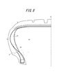
- FIG. 8 is a tire width direction cross-sectional view of a tire according to an embodiment of the present invention when the tire of the present invention is a run-flat tire.
- the folded end A of the carcass folded portion is located on the inner side in the tire radial direction from the tire maximum width position P.
- the tire is assembled into the rim, filled with a predetermined internal pressure
- the maximum tire radial direction length of the side reinforcing rubber 81 in the tire width direction cross section in the reference state as a load is H1
- the outermost point in the tire radial direction of the bead filler is connected to the outermost point in the tire radial direction of the bead core.
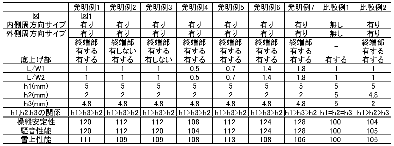
- Invention Example 1 is a tire having the tread pattern shown in FIG.
- the differences between the tires according to Invention Examples 2 to 7 and Comparative Examples 1 and 2 from Invention Example 1 are as follows. First, in the tire according to Invention Example 2, the outer circumferential sipe continuously extends in the tread circumferential direction, and does not have a terminal portion in the land portion 3d. Further, the tire according to Invention Example 3 does not have the bottom raised portion 7 in the circumferential main groove 2c. Further, the tires according to Invention Examples 4 to 7 are different from Invention Example 1 in the ratio L / W1 and the ratio L / W2.
- Comparative Example 1 does not have an inner circumferential sipe and an outer circumferential sipe, and the relationship between h1, h2, and h3 is different from that of Invention Example 1. Further, Comparative Example 2 is different from Invention Example 1 in the relationship between h1, h2, and h3. The specifications of each tire are shown in Table 1 below.
- the tire size 175 / 60R18 is mounted on the rim, the inner pressure is set to 320 kPa, the tire is mounted on the vehicle so that the one-sided opening lateral groove 13 is located on the outer half when the vehicle is mounted, and the tire performance is evaluated below.
- the test was conducted. ⁇ Steering stability> About each said tire, the driving
- the evaluation result of the tire according to Comparative Example 1 is evaluated as a relative value when the value is 100, and a larger numerical value indicates better steering stability.
- the tires according to Invention Examples 1 to 7 are both capable of achieving a high level of handling stability and performance on snow as compared with the tires according to Comparative Examples 1 and 2.
- Invention Example 1 and Invention Example 3 it can be seen from comparison between Invention Example 1 and Invention Example 3 that Invention Example 1 in which the bottom-up portion is provided in the circumferential main groove has better performance on snow than Invention Example 3.
- the invention example 5 in which the ratio L / W1 and the ratio L / W2 are 0.7 or more has improved performance on snow than the invention example 4, and the ratio L / W1 and the ratio L / W2 are 1.4 or less.
Landscapes
- Engineering & Computer Science (AREA)
- Mechanical Engineering (AREA)
- Tires In General (AREA)
Abstract
Description
本発明の空気入りタイヤは、トレッド踏面に、トレッド端に最も近いトレッド周方向に延びる最外側周方向主溝とトレッド端とにより区画される幅方向最外側陸部を有し、前記幅方向最外側陸部は、トレッド幅方向外側に延びる側方サイプをトレッド周方向に間隔を空けて複数本有し、前記幅方向最外側陸部は、トレッド周方向に延びる内側周方向サイプと、該内側周方向サイプよりトレッド幅方向外側に位置し、トレッド周方向に延びる外側周方向サイプとを有し、前記最外側周方向主溝の溝深さをh1、前記内側周方向サイプのサイプ深さをh2、前記外側周方向サイプのサイプ深さをh3とするとき、
h1>h3>h2
を満たすことを特徴とするものである。
また、「溝深さ」、「サイプの深さ」とは、平均深さをいうものとする。
なお、図2は、後述する第二の一端開口サイプ15及び中間サイプ16の本数以外は、図1と同様のトレッドパターンを有するタイヤの部分斜視図である。
ここでいう、「トレッド端TE」とは、タイヤを適用リムに装着し、規定内圧を充填し、上記最大負荷能力に対応する荷重(最大負荷荷重)を負荷した際の接地面のトレッド幅方向の最外位置をいうものとする。
ここで、周方向主溝2aの溝幅は、例えば、7~10mmとすることができ、周方向主溝2bの溝幅は、例えば、5~8mmとすることができ、周方向主溝2cの溝幅は、例えば、2~5mmとすることができる。
また、周方向主溝2aの溝深さは、例えば、6~8mmとすることができ、周方向主溝2bの溝深さは、例えば、6~8mmとすることができ、周方向主溝2cの溝深さは、例えば、6~8mmとすることができる。
なお、「溝幅」、「溝深さ」については、タイヤを適用リムに装着し、規定内圧を充填し、無負荷状態とした際の溝のトレッド踏面への開口幅、及び溝の平均深さをそれぞれ意味するものであり、以下、他の溝やサイプについても同様である。
さらに、図1~3に示すように、本実施形態のタイヤは、陸部3dにおいて、内側周方向サイプ5のトレッド幅方向外側にて、第一の側方サイプ4のうち、トレッド端TEよりトレッド幅方向外側の領域でラグ溝4Aに接続する2本の第一の側方サイプ4間に、トレッド周方向に延びる1本の外側周方向サイプ6をそれぞれ有している。
以下、本実施形態の作用効果について説明する。以下の作用効果の説明は、陸部3dが車両装着内側となるようにタイヤを車両に装着した際の作用効果についての説明である。
そして、h1>h3>h2を満たすことにより、以下のような作用効果が得られる。すなわち、周方向主溝2cは、排水性の観点からある程度の深さを有することが好ましい。この前提の下で内側周方向サイプ5のサイプ深さを深くし過ぎると、周方向主溝2cと内側周方向サイプ5との間の陸部の剛性が低下しすぎて操縦安定性が低下する。このため、内側周方向サイプ5のサイプ深さは、周方向主溝2cの溝深さより浅くして操縦安定性を確保する。一方で、外側周方向サイプ6のサイプ深さまで浅くすると、摩耗時に周方向サイプが早期になくなってしまうため、摩耗時の雪上性能が一気に低下してしまう。そこで、外側周方向サイプ6のサイプ深さh3は、内側周方向サイプ5のサイプ深さh2より深さする。ここで、内側周方向サイプ5のサイプ深さh2が浅く設定されているため、外側周方向サイプ6のサイプ深さh3をh2より深くしても、周方向サイプ5、6間の陸部の剛性が低下し過ぎることもない。一方で、周方向サイプ5、6は、周方向主溝2cと比較して、排水性への寄与が少なく、また、陸部の剛性を下げすぎない観点から、周方向サイプ5、6のサイプ深さh2、h3は、いずれも、周方向主溝2cの溝深さh1より浅くする。
このように、本実施形態のタイヤによれば、操縦安定性及び雪上性能を向上させることができる。
このためブロックの剛性を過度に低下させることなく、操縦安定性や騒音性能を確保することができる。このため、外側周方向サイプ6は、トレッド幅方向外側の領域でラグ溝4Aに接続する第一の側方サイプ4と1.5mm以上離間させることが好ましい。
なお、図1に示す実施形態では、内圧を250kPa以上とした際に、タイヤの断面幅SWが165(mm)未満である場合は、タイヤの断面幅SWと外径ODとの比SW/ODは、0.26以下であり、タイヤの断面幅SWが165(mm)以上である場合は、タイヤの断面幅SWおよび外径ODは、関係式、OD≧2.135×SW+282.3、を満たす狭幅タイヤであるため、底上げ部7を設けても、ウェット性能を十分に確保することができる。
0.7≦L/W1≦1.4、且つ、0.7≦L/W1≦1.4
を満たすことが好ましい。
比L/W1及び比L/W2を1に近づけることにより、サイプにより区画される陸部の捩れ剛性が高まり、旋回時の雪上性能をさらに向上させることができるからである。
これらの側方横溝8及び第二の側方サイプ9により直進方向に対するエッジ成分を確保して直進時の雪上性能を向上させつつも、全てを側方横溝8とせず、側方横溝8と第二の側方サイプ9との組み合わせとすることにより、陸部3aの剛性が過度に低下しないようにして、操縦安定性や騒音性能を確保することができる。
また、第二の側方サイプ9のサイプ幅は、例えば0.5~1.5mmとすることができ、また、サイプ深さは、6~8mmとすることができる。また、第二の側方サイプ9の両端部を結んだ直線がトレッド幅方向に対してなす角度を、第二の側方サイプ9のトレッド幅方向に対する傾斜角度とするとき、第二の側方サイプ9の傾斜角度は、40°以下であることが好ましい。40°以下とすることにより、上述した直進時の雪上性能を有効に得ることができるからである。
この側方周方向サイプ10により、特に操縦安定性への影響の大きい車両装着外側陸部において、横力方向に対するエッジ成分を確保することができ、旋回時の雪上性能をさらに向上させることができる。
なお、側方周方向サイプ10のサイプ幅は、例えば0.5~1.5mm、サイプ深さは、例えば6~8mmとすることができる。
なお、図1に示す実施形態では、内圧を250kPa以上とした際に、タイヤの断面幅SWが165(mm)未満である場合は、タイヤの断面幅SWと外径ODとの比SW/ODは、0.26以下であり、タイヤの断面幅SWが165(mm)以上である場合は、タイヤの断面幅SWおよび外径ODは、関係式、OD≧2.135×SW+282.3、を満たす狭幅タイヤであるため、底上げ部11を設けても、ウェット性能を十分に確保することができる。
ここで、一端開口横溝13の溝幅(最大幅)は、例えば3~5mmとすることができ、また、溝深さは、6~8mmとすることができる。
また、第一の一端開口サイプ14のサイプ幅は、例えば0.5~1.5mmとすることができ、また、サイプ深さは、2~4mmとすることができる。
さらに、「一端開口横溝」、「一端開口サイプ」とは、一端が周方向主溝に開口し、他端が周方向主溝や横溝に開口しないことを意味するが、該他端が周方向細溝やサイプに連通するものは含むものとする。
まず、本実施形態のタイヤにおいて、周方向主溝2a付近は、剛性が低下するため、コーナリング時に路面からの入力の影響を大きく受けることとなる。具体的には、車両装着外側での圧縮応力と車両装着内側での引張応力とにより、トレッドゴムが変形し、ベルトが変形して、接地面が浮き上がるバックリング現象が発生するおそれがある。これに対し、本実施形態のタイヤでは、上述の一端開口横溝13を設けているため、車両装着外側においては、圧縮応力により一端開口横溝13が閉じる構造となるため、トレッドゴムやベルトの変形を抑制することができる。さらに、一端開口横溝13がリブ状陸部3b内で終端するため、車両装着内側での引張応力に対する剛性が高くなり、これによりトレッドやベルトの変形が抑制される。従って、本実施形態によれば、まずバックリングの発生を抑制することができる。
さらに、周方向サイプ12と一端開口横溝13とが連通することにより、陸部3bにブロックの角部が形成されることとなるため、直進方向及び横力方向に対するエッジ効果が増大して、直進時の雪上性能及び旋回時の雪上性能を向上させることができる。
さらにまた、上記の第一の一端開口サイプ14を設けているため、直進方向に対するエッジ成分をさらに増大させて、直進時の雪上性能を向上させることができる。ここで、第一の一端開口サイプ14は、周方向サイプ12とは連通しないため、リブ状陸部3bの剛性が過度に低下することがなく、操縦安定性及び騒音性能も確保することができる。
従って、操縦安定性、騒音性能、及び雪上性能をより一層両立させることができる。
ここで、第二の一端開口サイプ15のサイプ幅は、例えば0.5~1.5mmとすることができ、また、サイプ深さは、6~8mmとすることができる。
このように、本発明のタイヤにあっては、一端開口横溝5間に、一方の周方向主溝2aからトレッド幅方向に、周方向サイプ12に連通する位置まで延びて、リブ状陸3b部内にて終端する、1本以上の第二の一端開口サイプ15を有することが好ましい。
また、第一の一端開口サイプ14のトレッド周方向のピッチ間隔は、10~15mmとすることが好ましい。10mm以上とすることにより、陸部の剛性を確保して、操縦安定性や騒音性能を確保することができ、一方で、15mm以下とすることにより、上述した直進時の雪上性能の向上効果をより一層有効に得ることができるからである。
さらに、第二の一端開口サイプ15のトレッド周方向のピッチ間隔は、10~15mmとすることが好ましい。10mm以上とすることにより、陸部の剛性を確保して、操縦安定性や騒音性能を確保することができ、一方で、15mm以下とすることにより、上述した直進時の雪上性能の向上効果をより一層有効に得ることができるからである。
また、図1に示すように、第一の一端開口サイプ14と第二の一端開口サイプ15とは、トレッド周方向に位相差を設けて配置することが好ましい。パターンノイズの発生を抑制することができ、また、陸部の剛性バランスを均一化することができるからである。
一般的に空気入りタイヤでは、タイヤ赤道面CLにおいて接地長が最も長くなるため、この位置に第一の一端開口サイプ14が配置されていることにより、直進時の雪上性能を効果的に高めることができるからである。また、この場合、一端開口横溝13が、タイヤ装着時外側に位置することとなるため、上述したようにバックリング抑制効果を得やすくなる。
また、第一の一端開口サイプ14の両端部を結んだ直線がトレッド幅方向に対してなす角度を、第一の一端開口サイプ14のトレッド幅方向に対する傾斜角度とするとき、第一の一端開口サイプ14の傾斜角度は、35°以下であることが好ましい。35°以下とすることにより、上述した直進時の雪上性能を有効に得ることができるからである。
さらに、第二の一端開口サイプ15の両端部を結んだ直線がトレッド幅方向に対してなす角度を、第二の一端開口サイプ15のトレッド幅方向に対する傾斜角度とするとき、第一の一端開口サイプ15の傾斜角度は、40°以下であることが好ましい。40°以下とすることにより、上述した直進時の雪上性能を有効に得ることができるからである。
一端開口横溝13が車両装着外側半部に位置するように、タイヤを車両に装着した際には、陸部3cは、車両装着内側となるが、乗り心地性に大きく影響する車両装着内側の陸部3cにリブ状陸部が形成されるため、乗り心地性を効果的に向上させることができる。また、中間サイプ16により、直進方向に対するエッジ成分を確保して、直進時の雪上性能をさらに向上させることができる。
さらに、中間サイプ16の両端部を結んだ直線がトレッド幅方向に対してなす角度を、中間サイプ16のトレッド幅方向に対する傾斜角度とするとき、中間サイプ16の傾斜角度は、15°以上であることが好ましい。進行方向のみならず、進行方向と横力方向との両方のエッジ成分を確保することができるため、直進時及び旋回時の雪上性能を総合的に向上させることができるからである。
さらにまた、中間サイプ16のトレッド幅方向の延在長さは、陸部3cのトレッド幅方向の幅の40~80%とすることが好ましい。40%以上とすることにより、エッジ成分を十分に確保して直進時の雪上性能をより一層向上させることができ、一方で、80%以下とすることにより、十分な幅のリブ状陸部を形成して、乗り心地性を向上させることができるからである。
高弾性ゴムとは、具体的には30℃における動的貯蔵弾性率E’が、6.0~12.0MPaであることが好ましい。この範囲を満たすことにより、狭幅大径サイズの乗用車用空気入りラジアルタイヤにおいてウェット性能をさらに向上させることができる。さらにトレッドゴムの60℃における損失正接tanδが、0.05~0.15であることが好ましい。この範囲を満たすことにより、転がり抵抗をさらに低減することができる。
傾斜角度を35°以上とすることにより、タイヤ幅方向に対する剛性を高め、特にコーナリング時の操縦安定性能を向上させることができるからである。また、層間ゴムのせん断変形を減少させて、転がり抵抗性能を向上させることができるからである。
傾斜ベルト層のベルトコードの傾斜角度θ1、θ2が35°以上の場合には、周方向ベルトは、タイヤ赤道面CLを含む中央領域Cの単位幅あたりのタイヤ周方向剛性が、その他の領域の単位幅あたりのタイヤ周方向剛性より高いことが好ましい。
図5は、ベルト構造の一例を概略的に示しており、傾斜ベルト層51、52のタイヤ径方向外側に周方向ベルト層53、54が積層されており、中央領域Cにおいて、周方向ベルト層53、54が互いにタイヤ径方向に重なっている。
例えば、図5に示すように、当該中央領域Cにおける周方向ベルト層の層数をその他の領域より多くすることにより、中央領域Cの単位幅あたりのタイヤ周方向剛性を、その他の領域の単位幅あたりのタイヤ周方向剛性より高くすることができる。
傾斜ベルト層のベルトコードがタイヤ周方向に対して35°以上で傾斜するタイヤの多くは、400Hz~2kHzの高周波域において、断面方向の1次、2次および3次等の振動モードにて、トレッド踏面が一律に大きく振動する形状となるため、大きな放射音が生じる。そこで、トレッドのタイヤ幅方向中央領域のタイヤ周方向剛性を局所的に増加させると、トレッドのタイヤ幅方向中央領域がタイヤ周方向に広がり難くなり、トレッド踏面のタイヤ周方向への広がりが抑制される結果、放射音を減少させることができる。
さらに、上述のごとく、タイヤ赤道面CLを含む中央領域のタイヤ周方向の剛性を高めたタイヤでは、トレッドはトレッド踏面の少なくともタイヤ赤道面CLを含む領域に、タイヤ周方向に連続する陸部を有することが好ましい。タイヤ赤道面CL上又はその付近に周方向主溝を配置すると、当該領域におけるトレッドの剛性が低下して、該周方向主溝を区画する陸部における接地長が極端に短くなる場合がある。そこで、タイヤ赤道面CLを含む一定領域にわたって、タイヤ周方向に連続する陸部(リブ状陸部)を配置することが、コーナリングパワーを低減させることなく騒音性能を改善する観点から好ましい。
本発明にあっては、図6に示す例のように、傾斜ベルト層のベルトコードの傾斜角度が35°以上の場合には、傾斜ベルト層は、タイヤ幅方向の幅の異なる2層の傾斜ベルト層を少なくとも含み、最広幅の傾斜ベルト層をなすコードのタイヤ周方向に対する傾斜角度θ1と、最狭幅の傾斜ベルト層をなすコードのタイヤ周方向に対する傾斜角度θ2とが、35°≦θ1≦85°、10°≦θ2≦30°、及び、θ1>θ2を満たすことが好ましい。
タイヤ周方向に対して35°以上で傾斜するベルトコードを有する傾斜ベルト層を備えたタイヤの多くは、400Hz~2kHzの高周波域において、断面方向の1次、2次および3次等の振動モードにて、トレッド踏面が一律に大きく振動する形状となるため、大きな放射音が生じる。そこで、トレッドのタイヤ幅方向中央領域のタイヤ周方向剛性を局所的に増加させると、トレッドのタイヤ幅方向中央領域がタイヤ周方向に広がり難くなり、トレッド面のタイヤ周方向への広がりが抑制される結果、放射音を減少させることができる。
上記関係式(1)を満たすような、狭幅大径サイズの乗用車用ラジアルタイヤにおいては、周方向ベルト層は高剛性であることが好ましく、より具体的にはタイヤ周方向に延びるコードのゴム引き層からなり、コードのヤング率をY(GPa)、打ち込み数をn(本/50mm)とし、周方向ベルト層をm層として、X=Y×n×mと定義するとき、1500≧X≧750であることが好ましい。上記関係式(1)及び/又は(2)を満たすような、狭幅大径サイズの乗用車用ラジアルタイヤにおいては、路面からの旋回時における入力に対しタイヤ周方向において局所的な変形を起こし、接地面は略三角形状、すなわち、タイヤ幅方向の位置によって周方向の接地長が大きく変化する形状となりやすい。これに対し、高剛性の周方向ベルト層とすることにより、タイヤのリング剛性が向上して、タイヤ周方向の変形が抑制されることとなるため、ゴムの非圧縮性により、タイヤ幅方向の変形も抑制され、接地形状が変化しにくくなる。さらには、リング剛性が向上することにより偏心変形が促進され、転がり抵抗も同時に向上する。この転がり抵抗の向上効果は、上記関係式(1)を満たすような、狭幅大径サイズの乗用車用空気入りラジアルタイヤにおいて、特に向上効果の幅が大きくなる。
なお、ゲージTsはゴム、補強部材、インナーライナーなどすべての部材の厚みの合計となる。また、ビードコアがカーカスによって複数の小ビードコアに分割されている構造の場合には、全小ビードコアのうち幅方向最内側端部と最外側端部の距離をTbとする。
上記関係式(1)を満たす、狭幅大径サイズの乗用車用空気入りラジアルタイヤは特に高内圧使用化において80-100Hzの車内騒音が悪化しやすいという知見が得られている。インナーライナーを厚くすることで振動減衰性を高め、80-100Hzの車内騒音を低減することができる。なお、インナーライナーは転がり抵抗に寄与するロスが、トレッド等の他の部材と比較すると小さいため、転がり抵抗の悪化を最小限にとどめつつ、騒音性能を改善することができる。
具体的な簡素化手法としては少なくとも以下の(i)~(iii)のいずれか一つの条件を満たすことにより可能となる。
図8は、本発明のタイヤがランフラットタイヤである場合における、本発明の一実施形態にかかるタイヤのタイヤ幅方向断面図である。
(i)図8に示すように、カーカス折り返し部の折り返し端Aが、タイヤ最大幅位置Pよりタイヤ径方向内側に位置する、(ii)タイヤをリムに組み込み、所定の内圧を充填し、無負荷とした、基準状態の際のタイヤ幅方向断面における、サイド補強ゴム81のタイヤ径方向最大長さをH1とし、ビードフィラのタイヤ径方向最外側点とビードコアのタイヤ径方向最外側点とを結んだ線分の長さをH2とするとき、1.8≦H1/H2≦3.5、を満たす(ここで、図8の例のように、ビードフィラのタイヤ径方向最外点とビードコアのタイヤ径方向最外点とを結んだ線分の長さH2が複数存在する場合は、そのうち最大のものを、該長さH2として用いる)、(iii)タイヤをリムに組み込み、所定の内圧を充填し、無負荷とした、基準状態の際のタイヤ幅方向断面における、サイド補強ゴム81のタイヤ径方向最大長さをH1(mm)とするとき、関係式、10(mm)≦(SW/OD)×H1≦20(mm)を満たす。
<操縦安定性>
上記各タイヤについて、ドライ路面上を走行した際の走行性能をドライバーによる官能により評価した。比較例1にかかるタイヤの評価結果を100とした場合の相対値で評価し、数値が大きい方が操縦安定性に優れていることを示す。
<騒音性能>
走行試験用ドラム上で、当該ドラムを100km/hの速度で回転させるとともに、マイク移動式でノイズレベルを測定した。比較例1のノイズレベルを基準としたノイズレベルの差を評価した。数値が低いほど、騒音の低減効果が良好であることを示す。
<雪上性能>
停止状態から30km/hになるまでの時間の逆数をとった。比較例1を100とした相対値で指数評価しており、数値が大きい方が雪上性能に優れていることを示している。
これらの評価結果をタイヤ諸元とともに以下の表1に示している。
2、2a、2b、2c 周方向主溝
3a、3b、3c、3d 陸部
4 第一の側方サイプ
5 内側周方向サイプ
6 外側周方向サイプ
7 底上げ部
8 側方横溝
9 第二の側方サイプ
10 側方周方向サイプ
11 底上げ部
12 周方向サイプ
13 一端開口横溝
14 第一の一端開口サイプ
15 第二の一端開口サイプ
16 中間サイプ
TE トレッド端
Claims (4)
- トレッド踏面に、トレッド端に最も近いトレッド周方向に延びる最外側周方向主溝とトレッド端とにより区画される幅方向最外側陸部を有し、
前記幅方向最外側陸部は、トレッド幅方向外側に延びる側方サイプをトレッド周方向に間隔を空けて複数本有し、
前記幅方向最外側陸部は、トレッド周方向に延びる内側周方向サイプと、該内側周方向サイプよりトレッド幅方向外側に位置し、トレッド周方向に延びる外側周方向サイプとを有し、
前記最外側周方向主溝の溝深さをh1、前記内側周方向サイプのサイプ深さをh2、前記外側周方向サイプのサイプ深さをh3とするとき、
h1>h3>h2
を満たすことを特徴とする、空気入りタイヤ。 - 前記内側周方向サイプは、トレッド周方向に連続して延び、前記外側周方向サイプは、前記幅方向最外側陸部内で終端部を有する、請求項1に記載の空気入りタイヤ。
- 前記側方サイプは、前記最外側周方向主溝に連通し、
前記側方サイプが前記最外側周方向主溝に連通する位置において、前記最外側周方向主溝の溝底に底上げ部を設けた、請求項1又は2に記載の空気入りタイヤ。 - 前記側方サイプのトレッド周方向のピッチ間隔をL、前記最外側周方向主溝と前記内側周方向サイプとの間のトレッド幅方向の距離をW1、前記内側周方向サイプと前記外側周方向サイプとのトレッド幅方向の距離をW2とするとき、
0.7≦L/W1≦1.4、且つ、0.7≦L/W2≦1.4
を満たす、請求項1~3のいずれか一項に記載の空気入りタイヤ。
Priority Applications (4)
| Application Number | Priority Date | Filing Date | Title |
|---|---|---|---|
| US15/307,645 US10035380B2 (en) | 2014-05-29 | 2015-05-28 | Pneumatic tire |
| JP2016523162A JP6605459B2 (ja) | 2014-05-29 | 2015-05-28 | 空気入りタイヤ |
| CN201580027516.8A CN106414114B (zh) | 2014-05-29 | 2015-05-28 | 充气轮胎 |
| EP15799184.5A EP3150407B1 (en) | 2014-05-29 | 2015-05-28 | Pneumatic tire |
Applications Claiming Priority (2)
| Application Number | Priority Date | Filing Date | Title |
|---|---|---|---|
| JP2014111654 | 2014-05-29 | ||
| JP2014-111654 | 2014-05-29 |
Publications (1)
| Publication Number | Publication Date |
|---|---|
| WO2015182151A1 true WO2015182151A1 (ja) | 2015-12-03 |
Family
ID=54698496
Family Applications (1)
| Application Number | Title | Priority Date | Filing Date |
|---|---|---|---|
| PCT/JP2015/002709 Ceased WO2015182151A1 (ja) | 2014-05-29 | 2015-05-28 | 空気入りタイヤ |
Country Status (5)
| Country | Link |
|---|---|
| US (1) | US10035380B2 (ja) |
| EP (1) | EP3150407B1 (ja) |
| JP (1) | JP6605459B2 (ja) |
| CN (1) | CN106414114B (ja) |
| WO (1) | WO2015182151A1 (ja) |
Cited By (3)
| Publication number | Priority date | Publication date | Assignee | Title |
|---|---|---|---|---|
| EP3130482A4 (en) * | 2014-05-30 | 2017-05-31 | Bridgestone Corporation | Pneumatic radial tire for use on passenger vehicle |
| JP2017197109A (ja) * | 2016-04-28 | 2017-11-02 | 株式会社ブリヂストン | タイヤ |
| JP2020104848A (ja) * | 2016-03-04 | 2020-07-09 | 住友ゴム工業株式会社 | 空気入りタイヤ |
Families Citing this family (7)
| Publication number | Priority date | Publication date | Assignee | Title |
|---|---|---|---|---|
| JP6571093B2 (ja) * | 2014-09-11 | 2019-09-04 | 株式会社ブリヂストン | 空気入りタイヤ |
| USD794540S1 (en) * | 2015-07-21 | 2017-08-15 | Cooper Tire & Rubber Company | Tire tread |
| JP6933006B2 (ja) * | 2017-06-09 | 2021-09-08 | 横浜ゴム株式会社 | 空気入りタイヤ |
| US10836215B2 (en) | 2017-06-27 | 2020-11-17 | Sumitomo Rubber Industries, Ltd. | Tire |
| JP7631764B2 (ja) * | 2020-12-01 | 2025-02-19 | 住友ゴム工業株式会社 | タイヤ |
| DE102021211351A1 (de) * | 2021-10-07 | 2023-04-13 | Continental Reifen Deutschland Gmbh | Fahrzeugluftreifen |
| CN119610948B (zh) * | 2024-11-29 | 2025-11-04 | 风神轮胎股份有限公司 | 一种用于提升中长途运输里程的低噪声胎面花纹上的刀槽花纹及胎面花纹及轮胎 |
Citations (6)
| Publication number | Priority date | Publication date | Assignee | Title |
|---|---|---|---|---|
| JPH0632115A (ja) * | 1992-07-20 | 1994-02-08 | Bridgestone Corp | 空気入りタイヤ |
| JP2005153812A (ja) * | 2003-11-28 | 2005-06-16 | Bridgestone Corp | 空気入りタイヤ |
| JP2007106258A (ja) * | 2005-10-13 | 2007-04-26 | Bridgestone Corp | 空気入りタイヤ |
| JP2010247708A (ja) * | 2009-04-16 | 2010-11-04 | Bridgestone Corp | 空気入りタイヤ |
| JP2013193464A (ja) * | 2012-03-15 | 2013-09-30 | Sumitomo Rubber Ind Ltd | 空気入りタイヤ |
| JP2014088116A (ja) * | 2012-10-30 | 2014-05-15 | Sumitomo Rubber Ind Ltd | 空気入りタイヤ |
Family Cites Families (13)
| Publication number | Priority date | Publication date | Assignee | Title |
|---|---|---|---|---|
| US2708957A (en) * | 1950-01-04 | 1955-05-24 | Us Rubber Co | Anti-skid tire tread |
| JPH01254407A (ja) * | 1988-04-01 | 1989-10-11 | Yokohama Rubber Co Ltd:The | 空気入りタイヤ |
| JP2892042B2 (ja) * | 1989-06-06 | 1999-05-17 | 住友ゴム工業 株式会社 | 低騒音タイヤ |
| JP5044291B2 (ja) * | 2007-06-04 | 2012-10-10 | 東洋ゴム工業株式会社 | 空気入りタイヤ |
| JP4825288B2 (ja) | 2009-08-24 | 2011-11-30 | 住友ゴム工業株式会社 | 空気入りタイヤ |
| CN104816594B (zh) | 2010-03-29 | 2017-06-30 | 株式会社普利司通 | 轮胎 |
| FR2962372B1 (fr) * | 2010-07-06 | 2014-05-02 | Michelin Soc Tech | Dispositif de protection de bande de roulement |
| EP2610083B1 (en) * | 2010-08-25 | 2015-10-07 | Bridgestone Corporation | Pneumatic tire |
| JP5108924B2 (ja) | 2010-10-07 | 2012-12-26 | 住友ゴム工業株式会社 | 空気入りタイヤ |
| DE102011000851A1 (de) * | 2011-02-21 | 2012-08-23 | Continental Reifen Deutschland Gmbh | Laufstreifenprofil eines Fahrzeugluftreifens |
| JP5480868B2 (ja) | 2011-10-07 | 2014-04-23 | 住友ゴム工業株式会社 | 空気入りタイヤ |
| JP5480867B2 (ja) * | 2011-10-07 | 2014-04-23 | 住友ゴム工業株式会社 | 空気入りタイヤ |
| US20130153100A1 (en) * | 2011-12-14 | 2013-06-20 | Olivier Piffard | Tire with tread having improved wet traction |
-
2015
- 2015-05-28 CN CN201580027516.8A patent/CN106414114B/zh not_active Expired - Fee Related
- 2015-05-28 JP JP2016523162A patent/JP6605459B2/ja not_active Expired - Fee Related
- 2015-05-28 US US15/307,645 patent/US10035380B2/en active Active
- 2015-05-28 WO PCT/JP2015/002709 patent/WO2015182151A1/ja not_active Ceased
- 2015-05-28 EP EP15799184.5A patent/EP3150407B1/en active Active
Patent Citations (6)
| Publication number | Priority date | Publication date | Assignee | Title |
|---|---|---|---|---|
| JPH0632115A (ja) * | 1992-07-20 | 1994-02-08 | Bridgestone Corp | 空気入りタイヤ |
| JP2005153812A (ja) * | 2003-11-28 | 2005-06-16 | Bridgestone Corp | 空気入りタイヤ |
| JP2007106258A (ja) * | 2005-10-13 | 2007-04-26 | Bridgestone Corp | 空気入りタイヤ |
| JP2010247708A (ja) * | 2009-04-16 | 2010-11-04 | Bridgestone Corp | 空気入りタイヤ |
| JP2013193464A (ja) * | 2012-03-15 | 2013-09-30 | Sumitomo Rubber Ind Ltd | 空気入りタイヤ |
| JP2014088116A (ja) * | 2012-10-30 | 2014-05-15 | Sumitomo Rubber Ind Ltd | 空気入りタイヤ |
Cited By (6)
| Publication number | Priority date | Publication date | Assignee | Title |
|---|---|---|---|---|
| EP3130482A4 (en) * | 2014-05-30 | 2017-05-31 | Bridgestone Corporation | Pneumatic radial tire for use on passenger vehicle |
| JP2020104848A (ja) * | 2016-03-04 | 2020-07-09 | 住友ゴム工業株式会社 | 空気入りタイヤ |
| JP2017197109A (ja) * | 2016-04-28 | 2017-11-02 | 株式会社ブリヂストン | タイヤ |
| WO2017187834A1 (ja) * | 2016-04-28 | 2017-11-02 | 株式会社ブリヂストン | タイヤ |
| CN109070654A (zh) * | 2016-04-28 | 2018-12-21 | 株式会社普利司通 | 轮胎 |
| EP3597450A1 (en) * | 2016-04-28 | 2020-01-22 | Bridgestone Corporation | Tire |
Also Published As
| Publication number | Publication date |
|---|---|
| CN106414114B (zh) | 2018-06-29 |
| EP3150407A1 (en) | 2017-04-05 |
| US10035380B2 (en) | 2018-07-31 |
| JP6605459B2 (ja) | 2019-11-13 |
| CN106414114A (zh) | 2017-02-15 |
| EP3150407A4 (en) | 2017-06-14 |
| EP3150407B1 (en) | 2018-09-05 |
| US20170050471A1 (en) | 2017-02-23 |
| JPWO2015182151A1 (ja) | 2017-04-20 |
Similar Documents
| Publication | Publication Date | Title |
|---|---|---|
| JP6518660B2 (ja) | 空気入りタイヤ | |
| JP6516726B2 (ja) | 空気入りタイヤ | |
| JP6605459B2 (ja) | 空気入りタイヤ | |
| JP6537496B2 (ja) | 空気入りタイヤ | |
| JP6581574B2 (ja) | 乗用車用空気入りラジアルタイヤ | |
| JP6527750B2 (ja) | 空気入りタイヤ | |
| WO2016051651A1 (ja) | ランフラットタイヤ | |
| JP6649724B2 (ja) | 空気入りタイヤ | |
| WO2015170478A1 (ja) | 乗用車用空気入りラジアルタイヤ | |
| JP7031397B2 (ja) | ランフラットタイヤ | |
| JP7518750B2 (ja) | 乗用車用空気入りラジアルタイヤ | |
| JP6393658B2 (ja) | 空気入りタイヤ | |
| JP2017159865A (ja) | ランフラットタイヤ |
Legal Events
| Date | Code | Title | Description |
|---|---|---|---|
| 121 | Ep: the epo has been informed by wipo that ep was designated in this application |
Ref document number: 15799184 Country of ref document: EP Kind code of ref document: A1 |
|
| ENP | Entry into the national phase |
Ref document number: 2016523162 Country of ref document: JP Kind code of ref document: A |
|
| WWE | Wipo information: entry into national phase |
Ref document number: 15307645 Country of ref document: US |
|
| REEP | Request for entry into the european phase |
Ref document number: 2015799184 Country of ref document: EP |
|
| WWE | Wipo information: entry into national phase |
Ref document number: 2015799184 Country of ref document: EP |
|
| NENP | Non-entry into the national phase |
Ref country code: DE |