WO2015182500A1 - Fil de blindage équipé d'un accessoire de borne - Google Patents
Fil de blindage équipé d'un accessoire de borne Download PDFInfo
- Publication number
- WO2015182500A1 WO2015182500A1 PCT/JP2015/064712 JP2015064712W WO2015182500A1 WO 2015182500 A1 WO2015182500 A1 WO 2015182500A1 JP 2015064712 W JP2015064712 W JP 2015064712W WO 2015182500 A1 WO2015182500 A1 WO 2015182500A1
- Authority
- WO
- WIPO (PCT)
- Prior art keywords
- ring member
- terminal
- braided wire
- barrel
- wire
- Prior art date
- Legal status (The legal status is an assumption and is not a legal conclusion. Google has not performed a legal analysis and makes no representation as to the accuracy of the status listed.)
- Ceased
Links
Images


Classifications
-
- H—ELECTRICITY
- H01—ELECTRIC ELEMENTS
- H01R—ELECTRICALLY-CONDUCTIVE CONNECTIONS; STRUCTURAL ASSOCIATIONS OF A PLURALITY OF MUTUALLY-INSULATED ELECTRICAL CONNECTING ELEMENTS; COUPLING DEVICES; CURRENT COLLECTORS
- H01R9/00—Structural associations of a plurality of mutually-insulated electrical connecting elements, e.g. terminal strips or terminal blocks; Terminals or binding posts mounted upon a base or in a case; Bases therefor
- H01R9/03—Connectors arranged to contact a plurality of the conductors of a multiconductor cable, e.g. tapping connections
- H01R9/05—Connectors arranged to contact a plurality of the conductors of a multiconductor cable, e.g. tapping connections for coaxial cables
- H01R9/0518—Connection to outer conductor by crimping or by crimping ferrule
-
- H—ELECTRICITY
- H01—ELECTRIC ELEMENTS
- H01R—ELECTRICALLY-CONDUCTIVE CONNECTIONS; STRUCTURAL ASSOCIATIONS OF A PLURALITY OF MUTUALLY-INSULATED ELECTRICAL CONNECTING ELEMENTS; COUPLING DEVICES; CURRENT COLLECTORS
- H01R24/00—Two-part coupling devices, or either of their cooperating parts, characterised by their overall structure
- H01R24/38—Two-part coupling devices, or either of their cooperating parts, characterised by their overall structure having concentrically or coaxially arranged contacts
- H01R24/40—Two-part coupling devices, or either of their cooperating parts, characterised by their overall structure having concentrically or coaxially arranged contacts specially adapted for high frequency
- H01R24/56—Two-part coupling devices, or either of their cooperating parts, characterised by their overall structure having concentrically or coaxially arranged contacts specially adapted for high frequency specially adapted to a specific shape of cables, e.g. corrugated cables, twisted pair cables, cables with two screens or hollow cables
-
- H—ELECTRICITY
- H01—ELECTRIC ELEMENTS
- H01R—ELECTRICALLY-CONDUCTIVE CONNECTIONS; STRUCTURAL ASSOCIATIONS OF A PLURALITY OF MUTUALLY-INSULATED ELECTRICAL CONNECTING ELEMENTS; COUPLING DEVICES; CURRENT COLLECTORS
- H01R4/00—Electrically-conductive connections between two or more conductive members in direct contact, i.e. touching one another; Means for effecting or maintaining such contact; Electrically-conductive connections having two or more spaced connecting locations for conductors and using contact members penetrating insulation
- H01R4/10—Electrically-conductive connections between two or more conductive members in direct contact, i.e. touching one another; Means for effecting or maintaining such contact; Electrically-conductive connections having two or more spaced connecting locations for conductors and using contact members penetrating insulation effected solely by twisting, wrapping, bending, crimping, or other permanent deformation
- H01R4/18—Electrically-conductive connections between two or more conductive members in direct contact, i.e. touching one another; Means for effecting or maintaining such contact; Electrically-conductive connections having two or more spaced connecting locations for conductors and using contact members penetrating insulation effected solely by twisting, wrapping, bending, crimping, or other permanent deformation by crimping
- H01R4/20—Electrically-conductive connections between two or more conductive members in direct contact, i.e. touching one another; Means for effecting or maintaining such contact; Electrically-conductive connections having two or more spaced connecting locations for conductors and using contact members penetrating insulation effected solely by twisting, wrapping, bending, crimping, or other permanent deformation by crimping using a crimping sleeve
-
- H—ELECTRICITY
- H02—GENERATION; CONVERSION OR DISTRIBUTION OF ELECTRIC POWER
- H02G—INSTALLATION OF ELECTRIC CABLES OR LINES, OR OF COMBINED OPTICAL AND ELECTRIC CABLES OR LINES
- H02G15/00—Cable fittings
- H02G15/02—Cable terminations
- H02G15/025—Cable terminations for coaxial cables or hollow conductors
-
- H—ELECTRICITY
- H02—GENERATION; CONVERSION OR DISTRIBUTION OF ELECTRIC POWER
- H02G—INSTALLATION OF ELECTRIC CABLES OR LINES, OR OF COMBINED OPTICAL AND ELECTRIC CABLES OR LINES
- H02G1/00—Methods or apparatus specially adapted for installing, maintaining, repairing or dismantling electric cables or lines
- H02G1/14—Methods or apparatus specially adapted for installing, maintaining, repairing or dismantling electric cables or lines for joining or terminating cables
Definitions
- the present invention relates to a shielded electric wire with terminal fittings.
- Patent Document 1 discloses a conventionally known shielded electric wire with a terminal fitting.
- the shielded electric wire disclosed here has a configuration in which a core wire is covered with an inner cover, an outer periphery of the inner cover is covered with a braided wire, and the outer periphery is covered with an outer cover.
- the terminal portion of the jacket Prior to connection with the terminal fitting, the terminal portion of the jacket is removed over a predetermined length range, and the braided wire is exposed.
- a terminal fitting (shield terminal) formed in a cylindrical shape is fitted into the outer sheath of the shielded electric wire, and the braided wire exposed on the outer peripheral surface of the terminal fitting is folded back. And the attachment to the shield electric wire of a terminal metal fitting is completed by caulking a tightening ring from the top.
- the folded braided wire is sandwiched and held between the terminal fitting and the tightening ring.
- these surfaces sandwiching the braided wire are all flat surfaces without irregularities, and no catch on the braided wire is set. Therefore, there is a concern that the terminal fitting may move on the outer sheath of the electric wire, and it is difficult to fix the terminal fitting at a predetermined position of the braided wire.
- the conventional apparatus has a problem that the fixing strength of the terminal fitting to the shielded electric wire is low, and the tightening state of the terminal fitting is not stable.
- the present invention has been completed on the basis of the above-described circumstances, and can improve the fixing force of the terminal fitting to the shielded electric wire and stabilize the tightening state of the terminal fitting to the shielded electric wire.
- the purpose is to provide electric wires.
- the shielded electric wire with a terminal fitting of the present invention is a shielded electric wire with a terminal fitting in which the terminal fitting is attached to the terminal portion of the shielded electric wire with a braided wire interposed between the outer covering and the inner covering, and the terminal of the outer covering.
- An outer cover removing portion that exposes the braided wire by removing the portion, a main body portion that is formed in a substantially cylindrical shape that can be fitted to an outer peripheral surface of a portion of the outer sheath near the outer cover removing portion,
- a ring member made of conductive metal having a hooking edge formed so as to protrude outward along the circumferential direction at the front end of the main body, and a hooking edge of the braided wire exposed in the jacket removing part.
- a braided wire folded portion that is folded back to the outer peripheral surface side of the ring member, and a barrel portion that is formed on the terminal fitting and that caulks the outer circumferential surface of the braided wire folded portion at a position corresponding to the main body portion of the ring member.
- the braided wire is caulked at the barrel portion after passing over the hook edge formed protruding from the tip of the ring member. Therefore, even when a pulling force is applied to the electric wire, the braided wire is hooked on the hooking edge, whereby the holding of the electric wire can be strengthened.
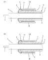
- (A) is sectional drawing which shows the state just before crimping the barrel part of an outer conductor with respect to a shielded electric wire in Example 1
- (B) is sectional drawing which similarly shows the state after crimping
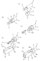
- (A) to (E) are diagrams showing the connection process of terminal fittings to shielded wires in order.
- (A) is sectional drawing which shows the state just before caulking the barrel part of an outer conductor with respect to a shielded electric wire in Example 2
- (B) is sectional drawing which shows the state after caulking similarly
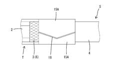
- the top view which shows the modification of a barrel part
- a split groove is provided over the entire length of the side surface of the ring member, and the ring member can be fitted into the shielded electric wire from a direction intersecting the axial direction. It is good to make it the structure formed in. Temporarily, when it is set as the structure which does not provide a split groove, although there is an annoyance which fits a ring member along an axial direction from a tip to a shield electric wire, according to the above composition, a ring member is shielded. Since the wire member can be fitted from the direction intersecting the axial direction, the ring member can be easily attached.
- the barrel portion is formed by a pair of barrel pieces, and when the braided wire folded portion is caulked, the end edges of the barrel pieces are butted over the entire length so as to be substantially cylindrical as a whole. It is preferable that the slit formed at the abutting portion between the end edges of the barrel pieces includes a portion extending in a direction intersecting with the folding direction of the braided wire. Since the braided wire folding portion is located at the terminal portion of the braided wire, the knitted state is unraveled and the strands are likely to fray. In such a state, when caulking is performed by the barrel portion, there is a possibility that the strands frayed from the boundary between the butted portions of the barrel pieces may protrude. However, according to the above configuration, if the butt portion of both barrel pieces includes a portion extending in a direction intersecting with the folding direction of the braided wire, the protruding of the frayed strands is effectively prevented. Can be suppressed.
- the end portion including the hooking edge portion of the ring member may be expanded and deformed into a trumpet shape as the barrel portion is caulked to form a bell mouth portion.
- the edge part of a ring member is expanded and deform
- the rear end positions of the barrel portion and the ring member may be substantially the same.
- the barrel portion is positioned with respect to the ring member with respect to the folding direction of the braided wire folding portion. Therefore, since the caulking position (region) of the barrel portion with respect to the ring member is stabilized, the form of the bell mouth part or the form of the throttle part can be made uniform.
- An end portion of the barrel portion corresponding to the hooking edge portion may be bent inward along the circumferential direction to form a throttle portion.
- Example 1> 1 and 2 show a shielded electric wire S with terminal fittings according to Embodiment 1 of the present invention.
- the shielded electric wire S has a core wire 1 provided along the central axis, and the outside thereof is covered with an inner sheath 2 formed of an insulating material having elasticity.
- the inner jacket 2 is covered with a braided wire 3 knitted in a cylindrical shape by a number of conductive metal strands, and the outer side thereof is covered with an outer jacket 4 made of an insulating material having elasticity.
- the shielded wire S is formed as a jacket removing portion 5 by peeling off the jacket 4 at the terminal portion, and the terminal portion of the braided wire 3 is exposed in the jacket removing portion 5.
- the exposed braided wire 3 is folded back when connecting to the terminal fitting T, and is put on the jacket 4.
- the braided wire 3 folded on the outer jacket 4 is referred to as a braided wire folded portion 6.
- a ring member 7 made of conductive metal (for example, brass) is fitted to the terminal portion (front end portion) of the jacket 4 (FIGS. 2A and 2B). )reference).
- the ring member 7 is integrally formed from a cylindrical main body portion 8 and a hooking edge portion 9 formed on one end side (front end side) of the main body portion 8.
- the main body portion 8 is formed with an inner diameter that can be fitted onto the outer peripheral surface of the outer cover 4 in a close contact state (or in a crimped state). Further, the hooking edge portion 9 is formed in a flange shape along the entire circumference of the main body portion 8. The hook edge portion 9 is formed by bending the distal end edge of the main body portion 8 outward at a substantially right angle.
- the ring member 7 is formed with a slit 10 extending along the axial direction over the entire length range including the hooking edge 9, and the entire ring member 7 can be opened and closed with the split groove 10 as a boundary. It has become.
- the ring member 7 is fitted to the outer sheath 4 of the shielded electric wire S from the side (in a direction orthogonal to the axis of the shielded electric wire S).
- the front end of the ring member 7 is positioned slightly behind the front end of the outer cover 4 as shown in FIG.
- the braided wire 3 is folded back onto the outer jacket 4, that is, the braided wire folded portion 6 is formed (the state shown in FIG. 2C).
- the braided wire folding portion 6 passes outward from the hooking edge portion 9 of the ring member 7 and extends rearward, and reaches the vicinity of the rear end of the ring member 7. That is, the ring member 7 is almost entirely covered with the braided wire folding portion 6.
- the terminal fitting T of the present embodiment includes an inner conductor terminal 11, an outer conductor terminal 12 connected to the ground, and an inner conductor incorporated in the outer conductor terminal 12.
- An insulator 13 into which the terminal 11 is fitted is included.
- the inner conductor terminal 11 is crimped and connected to the core wire 1 exposed by removing the tip of the inner jacket 2.
- a connecting portion 14 having a rectangular tube shape is formed in the front half of the outer conductor terminal 12, and the insulator 13 described above is incorporated in the inner portion of the outer conductor terminal 12 so as to prevent the inner conductor terminal 11 from being inserted inside the insulator 13. It is fitted in a retaining state.
- a barrel portion 15 is formed in the latter half of the outer conductor terminal 12 continuously to the connection portion 14.
- the barrel portion 15 has a pair of barrel pieces 15A formed to face each other in the width direction. Both barrel pieces 15 ⁇ / b> A are formed so as to extend obliquely so that the tip end is widened in the natural state, and can be caulked to the braided wire folding portion 6. Both barrel pieces 15A are configured to have a substantially cylindrical shape with their ends being abutted in a straight line along the front-rear direction in a caulked state. Both barrel pieces 15 ⁇ / b> A are formed with a front-rear width shorter than the front-rear width of the main body 8 of the ring member 7.
- the front end portion of the ring member 7 (the portion exposed forward from both barrel pieces 15A). Is deformed so as to be lifted over substantially the entire circumference including the hook edge 9.
- the front end portion of the ring member 7 is expanded in a trumpet shape to form the bell mouth portion 16. That is, as the bell mouth portion 16 is formed, the hooking edge portion 9 is separated from the outer cover 4 in the radially outward direction, so that the braided wire folded portion 6 is hooked on the hooking edge portion 9 in a more tensioned state. Therefore, a relative shift in the axial direction between the braided wire folding portion 6 and the ring member 7 can be effectively avoided. Therefore, the terminal metal fitting T is securely held with respect to the shielded electric wire S.
- this embodiment has the following effects. That is, since the split groove 10 is provided over the entire length of the ring member 7, the shield wire S can be fitted into the jacket 4 from the side. If the ring member 7 is simply formed in a cylindrical shape without providing the split groove 10, there is an inconvenience that it must be fitted along the axial direction from the tip of the shielded wire S. Since the split groove 10 of the member 7 is expanded, it can be easily fitted to the outer jacket 4, which contributes to improved workability.
- the rear end position of the ring member 7 is substantially aligned with the rear end position of both barrel pieces 15A.
- the ring member 7 and both barrel pieces 15A in the front-rear direction are relatively positioned. That is, the front end positions of both barrel pieces 15A with respect to the ring member 7 are determined. Therefore, since the position where the front end portion of the ring member 7 is lifted with the caulking of the barrel piece 15A is determined, the form of the bell mouth portion 16 is stabilized. This leads to stabilization of the holding force of the terminal fitting T with respect to the shielded electric wire S.
- Example 2> 3A and 3B show Embodiment 2 of the present invention.
- the narrowed portion 17 is formed in the barrel portion 15 of the outer conductor terminal 12 in advance, and the braided wire folding portion 6 is pushed down by caulking, so that the braided wire 3 is hooked to the hooking edge portion 9. It is designed to be hooked with a strong tension.
- both barrel pieces 15 ⁇ / b> A are configured to form the above-described throttle portion 17.
- a portion of the ring member 7 corresponding to the narrowed portion 17 is deformed so that the outer diameter is narrowed as the both barrel pieces 15A are caulked, and bites into the outer cover 4.
- the braided wire folded portion 6 passes through the hooking edge portion 9 of the ring member 7 and is narrowed in the diameter reducing direction by the restricting portion 17, the braided wire folding portion 6 is hooked in a strongly tensioned state against the hooking edge portion 9.
- the holding power of the terminal fitting T against S can be increased.
- Other configurations are the same as those of the first embodiment, and the same operational effects can be exhibited.
- FIG. 4 shows a modification regarding the barrel portion 15.
- the slit 18 generated when the tips of the barrel pieces 15A are abutted with each other is along the front-rear direction.
- the slit 18 is substantially V-shaped in the axial direction. I have to.
- the slit 18 is formed so as to intersect the folding direction of the braided wire 3.
- the braided wire folding portion 6 is a terminal portion of the braided wire 3, the knitted state is unraveled and is likely to fray.
- the extension direction of the slit 18 matches the extension direction of the frayed strand, so that the strands easily protrude from the slit 18.
- the slits 18 are formed in a direction intersecting with the folding direction of the braided wire 3, the protruding of the frayed strands can be effectively avoided.
- FIG. 5 shows another modification example regarding the barrel portion 15.
- the slit 19 is formed in a crank shape, and a portion that intersects with the folding direction of the braided wire 3 is generated before and after the detour portion. Such a shape of the slit 19 can effectively avoid the protruding of the frayed strands.
- the bell mouth portion 16 is formed at the front end portion of the ring member 7 as the barrel portion 15 is caulked.
- the bell mouth portion 16 is not formed during caulking. It is also possible. Even if it forms in this way, if the protrusion height of the hooking edge part 9 is set appropriately, the holding power of the terminal fitting T with respect to the shielded electric wire S can be obtained sufficiently.
- the hook edge 9 of the ring member 7 is formed along the entire circumference, but it may be formed in a part.
- the hook edge 9 may be projected outward by opening the mesh of the braided wire 3.
- the hooking edge portion 9 is bent at a substantially right angle with respect to the main body portion. However, the hooking edge portion 9 is bent more than 90 degrees obliquely, that is, so that the front end faces the folding direction of the braided wire folding portion 6. You may let them.
- FIGS. 4 and 5 the V-shaped or crank-shaped slits 18 and 19 of the butted portion of the barrel piece 15 ⁇ / b> A are shown. It may be applied to the split groove 10.
Landscapes
- Details Of Connecting Devices For Male And Female Coupling (AREA)
- Coupling Device And Connection With Printed Circuit (AREA)
- Insulated Conductors (AREA)
- Processing Of Terminals (AREA)
- Cable Accessories (AREA)
Abstract
L'objectif de la présente invention est d'augmenter la force avec laquelle un accessoire de borne est ancré à un fil de blindage. Un élément annulaire (7) est manchonné latéralement sur une gaine (4), et un fil tressé (3) est replié sur la surface périphérique extérieure de l'élément annulaire (7). Une partie bord recourbé (9) est formée pour faire saillie autour de toute la périphérie de la partie d'extrémité avant de l'élément annulaire (7). Une partie cylindrique (15) d'une borne de conducteur externe (12) est sertie sur le fil tressé (3) replié, et la partie bord recourbé (9) de l'élément annulaire (7) est ensuite agrandie d'une manière s'évasant vers l'extérieur avec le fil tressé (3) encore accroché sur la partie bord recourbé (9), et une partie évasée (16) est formée. Par conséquent, le fil tressé (3) et l'élément annulaire (7) sont accrochés d'une manière plus sûre, moyennant quoi la force avec laquelle un raccord de connexion (T) est maintenu sur un fil de blindage (S) est augmentée.
Priority Applications (1)
| Application Number | Priority Date | Filing Date | Title |
|---|---|---|---|
| US15/314,310 US9865942B2 (en) | 2014-05-28 | 2015-05-22 | Shield wire with terminal fitting |
Applications Claiming Priority (2)
| Application Number | Priority Date | Filing Date | Title |
|---|---|---|---|
| JP2014-109922 | 2014-05-28 | ||
| JP2014109922A JP6168416B2 (ja) | 2014-05-28 | 2014-05-28 | 端子金具付きシールド電線 |
Publications (1)
| Publication Number | Publication Date |
|---|---|
| WO2015182500A1 true WO2015182500A1 (fr) | 2015-12-03 |
Family
ID=54698834
Family Applications (1)
| Application Number | Title | Priority Date | Filing Date |
|---|---|---|---|
| PCT/JP2015/064712 Ceased WO2015182500A1 (fr) | 2014-05-28 | 2015-05-22 | Fil de blindage équipé d'un accessoire de borne |
Country Status (3)
| Country | Link |
|---|---|
| US (1) | US9865942B2 (fr) |
| JP (1) | JP6168416B2 (fr) |
| WO (1) | WO2015182500A1 (fr) |
Cited By (5)
| Publication number | Priority date | Publication date | Assignee | Title |
|---|---|---|---|---|
| US20210344125A1 (en) * | 2020-04-30 | 2021-11-04 | Rosenberger Hochfrequenztechnik Gmbh & Co. Kg | Outer conductor element, plug connector arrangement and assembly method for a plug connector arrangement |
| TWI790785B (zh) * | 2016-05-31 | 2023-01-21 | 美商安芬諾股份有限公司 | 電終端、纜線總成以及纜線端接方法 |
| US11637401B2 (en) | 2017-08-03 | 2023-04-25 | Amphenol Corporation | Cable connector for high speed in interconnects |
| US20230318278A1 (en) * | 2022-03-15 | 2023-10-05 | Yazaki Europe Ltd. | Shielded electric cable assembly |
| WO2026004434A1 (fr) * | 2024-06-28 | 2026-01-02 | 矢崎総業株式会社 | Dispositif de traitement de fil électrique et fil électrique équipé d'une borne |
Families Citing this family (10)
| Publication number | Priority date | Publication date | Assignee | Title |
|---|---|---|---|---|
| DE202015000751U1 (de) * | 2015-01-30 | 2015-03-06 | Rosenberger Hochfrequenztechnik Gmbh & Co. Kg | Steckverbinderanordnung mit Kompensationscrimp |
| JP6387059B2 (ja) * | 2016-09-16 | 2018-09-05 | 矢崎総業株式会社 | 端子金具固定構造およびワイヤハーネス |
| JP6780546B2 (ja) * | 2017-03-01 | 2020-11-04 | 株式会社オートネットワーク技術研究所 | 端子付きシールド電線 |
| DE102017122048A1 (de) * | 2017-09-22 | 2019-03-28 | Te Connectivity Germany Gmbh | Elektrische Kontaktvorrichtung, elektrische Verbindungseinrichtung, sowie Verfahren zum Konfektionieren eines elektrischen Kabels |
| JP6762339B2 (ja) * | 2018-05-21 | 2020-09-30 | 矢崎総業株式会社 | 端子の圧着方法及び圧着構造 |
| JP7406711B2 (ja) * | 2020-05-14 | 2023-12-28 | 株式会社オートネットワーク技術研究所 | シールド導電路 |
| US11670892B2 (en) * | 2020-07-14 | 2023-06-06 | J.S.T. Corporation | High voltage vertical disk ferrule, and method for assembling thereof |
| JP2022072614A (ja) * | 2020-10-30 | 2022-05-17 | 矢崎総業株式会社 | シールドコネクタ |
| DE102021129999A1 (de) | 2021-11-17 | 2023-05-17 | Te Connectivity Germany Gmbh | Verfahren zum Vercrimpen eines elektrischen Kabels und elektrisches Kabel |
| JP7763124B2 (ja) * | 2022-03-10 | 2025-10-31 | 古河電気工業株式会社 | シールド電線の端末構造、端子付き電線、コネクタ構造 |
Citations (2)
| Publication number | Priority date | Publication date | Assignee | Title |
|---|---|---|---|---|
| JP2002010469A (ja) * | 2000-06-20 | 2002-01-11 | Auto Network Gijutsu Kenkyusho:Kk | シールド電線の端末接続構造 |
| JP2012125009A (ja) * | 2010-12-07 | 2012-06-28 | Sumitomo Wiring Syst Ltd | シールドケーブル |
Family Cites Families (10)
| Publication number | Priority date | Publication date | Assignee | Title |
|---|---|---|---|---|
| US1687574A (en) * | 1926-11-30 | 1928-10-16 | Western Electric Co | Article-forming apparatus |
| US2293491A (en) * | 1939-12-11 | 1942-08-18 | Cox Robert Charles | Tubular rivet |
| US3103548A (en) * | 1961-11-16 | 1963-09-10 | Crimped coaxial cable termination | |
| US4280749A (en) * | 1979-10-25 | 1981-07-28 | The Bendix Corporation | Socket and pin contacts for coaxial cable |
| US4596440A (en) * | 1984-03-06 | 1986-06-24 | E. F. Johnson Company | Electrical probe contact |
| US5123864A (en) * | 1991-04-05 | 1992-06-23 | Amp Incorporated | Coaxial contact with sleeve |
| JP3928770B2 (ja) | 2001-01-17 | 2007-06-13 | 矢崎総業株式会社 | シールド電線の端末処理構造 |
| JP5622307B2 (ja) * | 2010-07-05 | 2014-11-12 | 矢崎総業株式会社 | シールドコネクタ |
| JP5762219B2 (ja) * | 2011-08-31 | 2015-08-12 | 矢崎総業株式会社 | シールド電線の編組シールド層とドレイン線との接続方法、及び、接続構造 |
| US8771013B2 (en) * | 2012-06-14 | 2014-07-08 | Tesla Motors, Inc. | High voltage cable connector |
-
2014
- 2014-05-28 JP JP2014109922A patent/JP6168416B2/ja not_active Expired - Fee Related
-
2015
- 2015-05-22 WO PCT/JP2015/064712 patent/WO2015182500A1/fr not_active Ceased
- 2015-05-22 US US15/314,310 patent/US9865942B2/en not_active Expired - Fee Related
Patent Citations (2)
| Publication number | Priority date | Publication date | Assignee | Title |
|---|---|---|---|---|
| JP2002010469A (ja) * | 2000-06-20 | 2002-01-11 | Auto Network Gijutsu Kenkyusho:Kk | シールド電線の端末接続構造 |
| JP2012125009A (ja) * | 2010-12-07 | 2012-06-28 | Sumitomo Wiring Syst Ltd | シールドケーブル |
Cited By (9)
| Publication number | Priority date | Publication date | Assignee | Title |
|---|---|---|---|---|
| TWI790785B (zh) * | 2016-05-31 | 2023-01-21 | 美商安芬諾股份有限公司 | 電終端、纜線總成以及纜線端接方法 |
| US11831106B2 (en) | 2016-05-31 | 2023-11-28 | Amphenol Corporation | High performance cable termination |
| US11637401B2 (en) | 2017-08-03 | 2023-04-25 | Amphenol Corporation | Cable connector for high speed in interconnects |
| US11824311B2 (en) | 2017-08-03 | 2023-11-21 | Amphenol Corporation | Connector for low loss interconnection system |
| US20210344125A1 (en) * | 2020-04-30 | 2021-11-04 | Rosenberger Hochfrequenztechnik Gmbh & Co. Kg | Outer conductor element, plug connector arrangement and assembly method for a plug connector arrangement |
| US11677166B2 (en) * | 2020-04-30 | 2023-06-13 | Rosenberger Hochfrequenztechnik Gmbh & Co. Kg | Outer conductor element, plug connector arrangement and assembly method for a plug connector arrangement |
| US20230318278A1 (en) * | 2022-03-15 | 2023-10-05 | Yazaki Europe Ltd. | Shielded electric cable assembly |
| US12424834B2 (en) * | 2022-03-15 | 2025-09-23 | Yazaki Europe Ltd. | Shielded electric cable assembly |
| WO2026004434A1 (fr) * | 2024-06-28 | 2026-01-02 | 矢崎総業株式会社 | Dispositif de traitement de fil électrique et fil électrique équipé d'une borne |
Also Published As
| Publication number | Publication date |
|---|---|
| US20170214153A1 (en) | 2017-07-27 |
| JP2015226383A (ja) | 2015-12-14 |
| US9865942B2 (en) | 2018-01-09 |
| JP6168416B2 (ja) | 2017-07-26 |
Similar Documents
| Publication | Publication Date | Title |
|---|---|---|
| JP6168416B2 (ja) | 端子金具付きシールド電線 | |
| US7491071B2 (en) | Shield end processing structure | |
| JP6780546B2 (ja) | 端子付きシールド電線 | |
| JP6508015B2 (ja) | ワイヤーハーネス、電線保護部材及び電線ホルダ | |
| JP6057176B2 (ja) | ホルダー | |
| CN103403970B (zh) | 同轴电缆的端子处理结构和端子处理方法 | |
| JP5352345B2 (ja) | 加締め型及びシールド電線の編組固定構造 | |
| JP7240607B2 (ja) | ケーブル付きコネクタ | |
| US20160226196A1 (en) | Contact spring washer and plug-in connector | |
| WO2014203845A1 (fr) | Unité de blindage | |
| JP6290957B2 (ja) | シールド端子の接続構造 | |
| JP2021028873A5 (fr) | ||
| WO2019063641A1 (fr) | Cylindre de support destiné à un conducteur électrique | |
| JP6033113B2 (ja) | シールド編組線の接続構造およびシールドコネクタ | |
| JP2020092063A (ja) | コネクタ端子 | |
| JP6731744B2 (ja) | シールド端子の接続方法 | |
| WO2021235190A1 (fr) | Dispositif de montage d'un manchon sur un câble coaxial, procédé de montage d'un manchon sur un câble coaxial, et chemin conducteur de blindage | |
| US20230178928A1 (en) | Shielded electrically conductive path | |
| JP2015232962A (ja) | 電線モジュール及びパイプ | |
| JP5344899B2 (ja) | 同軸ケーブル用コネクタ | |
| JP2015079651A (ja) | シールド電線の端末接続構造 | |
| JP2006310139A (ja) | シールドコネクタ | |
| JP3152597U (ja) | 同軸ケーブルロックコネクタ | |
| JP2010003588A (ja) | 端子金具及び端子金具とシールド電線の接続構造 | |
| JP6332085B2 (ja) | 金属製結束バンドを用いたアース接続構造 |
Legal Events
| Date | Code | Title | Description |
|---|---|---|---|
| 121 | Ep: the epo has been informed by wipo that ep was designated in this application |
Ref document number: 15800694 Country of ref document: EP Kind code of ref document: A1 |
|
| NENP | Non-entry into the national phase |
Ref country code: DE |
|
| WWE | Wipo information: entry into national phase |
Ref document number: 15314310 Country of ref document: US |
|
| 122 | Ep: pct application non-entry in european phase |
Ref document number: 15800694 Country of ref document: EP Kind code of ref document: A1 |