WO2015186221A1 - Dispositif d'alimentation en huile de joint pour machine dynamoélectrique, et procédé d'alimentation en huile de joint - Google Patents
Dispositif d'alimentation en huile de joint pour machine dynamoélectrique, et procédé d'alimentation en huile de joint Download PDFInfo
- Publication number
- WO2015186221A1 WO2015186221A1 PCT/JP2014/064936 JP2014064936W WO2015186221A1 WO 2015186221 A1 WO2015186221 A1 WO 2015186221A1 JP 2014064936 W JP2014064936 W JP 2014064936W WO 2015186221 A1 WO2015186221 A1 WO 2015186221A1
- Authority
- WO
- WIPO (PCT)
- Prior art keywords
- sealing oil
- electrical machine
- rotating electrical
- oil supply
- supply device
- Prior art date
- Legal status (The legal status is an assumption and is not a legal conclusion. Google has not performed a legal analysis and makes no representation as to the accuracy of the status listed.)
- Ceased
Links
Images



Classifications
-
- H—ELECTRICITY
- H02—GENERATION; CONVERSION OR DISTRIBUTION OF ELECTRIC POWER
- H02K—DYNAMO-ELECTRIC MACHINES
- H02K5/00—Casings; Enclosures; Supports
- H02K5/04—Casings or enclosures characterised by the shape, form or construction thereof
- H02K5/12—Casings or enclosures characterised by the shape, form or construction thereof specially adapted for operating in liquid or gas
- H02K5/124—Sealing of shafts
-
- F—MECHANICAL ENGINEERING; LIGHTING; HEATING; WEAPONS; BLASTING
- F16—ENGINEERING ELEMENTS AND UNITS; GENERAL MEASURES FOR PRODUCING AND MAINTAINING EFFECTIVE FUNCTIONING OF MACHINES OR INSTALLATIONS; THERMAL INSULATION IN GENERAL
- F16J—PISTONS; CYLINDERS; SEALINGS
- F16J15/00—Sealings
- F16J15/16—Sealings between relatively-moving surfaces
- F16J15/40—Sealings between relatively-moving surfaces by means of fluid
-
- F—MECHANICAL ENGINEERING; LIGHTING; HEATING; WEAPONS; BLASTING
- F16—ENGINEERING ELEMENTS AND UNITS; GENERAL MEASURES FOR PRODUCING AND MAINTAINING EFFECTIVE FUNCTIONING OF MACHINES OR INSTALLATIONS; THERMAL INSULATION IN GENERAL
- F16J—PISTONS; CYLINDERS; SEALINGS
- F16J15/00—Sealings
- F16J15/16—Sealings between relatively-moving surfaces
- F16J15/40—Sealings between relatively-moving surfaces by means of fluid
- F16J15/406—Sealings between relatively-moving surfaces by means of fluid by at least one pump
Definitions
- the present invention relates to a sealing oil supply device and a sealing oil supply method for a rotating electrical machine using hydrogen gas or the like as a cooling medium.
- a heat ring such as a coil is cooled by hydrogen gas sealed in the machine, and a seal ring is used to prevent leakage of hydrogen gas from the shaft penetration portion into the atmosphere.
- a sealing oil is supplied to the seal ring to seal hydrogen gas.
- the oil supply pressure for supplying oil to the seal ring is controlled by the differential pressure adjustment valve to control the differential pressure with the gas pressure in the machine.
- the gap between the rotary shaft and the seal ring is designed so that a sufficient gap is secured at this time. For this reason, the gap is larger than necessary and the amount of oil is larger than necessary during normal operation in which a sufficient pressure can be secured, so that there is a problem that each component of the sealing oil supply device of the rotating electrical machine becomes larger than necessary.
- the present invention has been made to solve the above-described problems, and by ensuring the necessary hydraulic pressure even when operating at an extremely low pressure close to a gas pressure of 0.00 MPa-g, such as during a trial operation, the rotating shaft
- the purpose is to reduce the amount of oil and reduce the size of the sealing oil supply device of the rotating electrical machine by suppressing the expansion due to the temperature rise and reducing the gap between the rotating shaft and the seal ring during normal operation.
- the sealing oil supply device for a rotating electrical machine supplies the sealing oil to a sealing ring of the rotating electrical machine in which hydrogen gas is sealed via a differential pressure adjusting valve that adjusts the oil pressure of the sealing oil from a sealing oil pump.
- a differential pressure adjusting valve that adjusts the oil pressure of the sealing oil from a sealing oil pump.
- the sealing oil supply method for a rotating electrical machine is configured such that the sealing oil is supplied to a sealing ring of a rotating electrical machine in which hydrogen gas is sealed via a differential pressure adjustment valve that adjusts the hydraulic pressure of the sealing oil from a sealing oil pump.
- the sealing oil supply method for a rotating electrical machine that is supplied, during the normal operation of the rotating electrical machine, the sealing oil is supplied from the sealing oil pump through a first path via the differential pressure regulating valve, and the rotation oil is supplied.
- the sealing oil is supplied from the sealing oil pump through a second path via a relief valve. .
- the required hydraulic pressure is ensured even when operating at an extremely low pressure close to a gas pressure of 0.00 MPa-g, such as during a trial operation, thereby suppressing expansion due to a temperature rise of the rotating shaft, and during normal operation.
- FIG. 1 is a system diagram showing a sealing oil supply device for a rotating electrical machine according to Embodiment 1 of the present invention, which is shown together with the rotating electrical machine.
- the rotating electrical machine is, for example, a hydrogen-cooled turbine generator.
- a rotating electrical machine 1 is provided in a rotating shaft 2 penetrating a sealed chamber 1a filled with hydrogen gas and bearing chambers provided at both ends in the axial direction of the rotating electrical machine 1 using sealing oil.
- a seal ring 3 is provided as a shaft seal portion that seals a gap between the sealed chamber 1a and the rotary shaft 2.
- the sealing oil discharged from the seal ring 3 is sent to the vacuum tank 5 through which the sealing oil is vacuum deaerated through the sealing oil drain pipe 4.
- the upstream side of the seal ring 3 and the vacuum chamber 5 are connected to each other by a seal oil supply pipe 6 that supplies seal oil to the seal ring 3.
- a sealing oil pump 7 for supplying the sealing oil in the vacuum chamber 5 to the seal ring 3 and a differential pressure adjusting valve 8 for adjusting the hydraulic pressure of the sealing oil supplied to the seal ring 3 are attached to the sealing oil supply pipe 6. It has been.
- the differential pressure adjusting valve 8 allows the sealing oil controlled so as to be higher than the hydrogen gas pressure inside the rotating electrical machine 1 by a certain value to pass therethrough.
- An oil level adjustment valve 11 for keeping the oil level of the sealing oil constant is attached to the vacuum chamber 5.
- the vacuum chamber 5 has a gas discharge pipe 12 for discharging a gas containing air, oil, moisture, hydrogen, etc., and this gas discharge pipe 12 is connected to a vacuum pump 13, and further the vacuum pump 13. The gas is discharged to the outside through the discharge pipe 14.
- a relief valve 15 having a set pressure of, for example, 0.1 to 0.2 MPa-g is provided on the downstream side of the sealing oil pump 7 in parallel with the differential pressure regulating valve 8. .
- the second path for supplying the sealing oil from the sealing oil pump 7 via the relief valve 15. Is formed.
- one end side of a sealing oil return pipe 10 for returning the sealing oil that cannot pass through the relief valve 15 to the vacuum chamber 5 is connected.
- check valves 16 and 17 are provided on the downstream side of the differential pressure adjusting valve 8 and the downstream side of the relief valve 15, respectively.
- the seal ring 3 is supplied with sealing oil from the sealing oil supply pipe 6 through the oil supply hole 3a as shown in an enlarged cross section in FIG.
- the hydrogen gas sealed in the machine of the rotating electrical machine 1 is prevented from leaking out of the machine.
- the hydrogen gas in the rotating electrical machine 1 is sealed with sealing oil that circulates in a sealing oil supply circuit connected to the seal ring 3 as shown in FIG.
- the sealing oil is sent out by the sealing oil pump 7 and is adjusted by the differential pressure adjusting valve 8 so as to be higher than the hydrogen gas in the rotating electrical machine 1 by a certain value.
- the adjusted sealing oil passes through the sealing oil supply pipe 6 and is sent to the seal ring 3.
- the seal oil in the seal ring 3 comes into contact with the outside air, contains air, moisture, hydrogen gas, etc., passes through the seal oil drain pipe 4 and is collected into the vacuum tank 5 and is vacuum degassed in the vacuum tank 5.
- the degassed gas deaerated in the vacuum chamber 5 is sent to the vacuum pump 13 through the gas discharge pipe 12, and is discharged to the outside through the discharge pipe 14 from there.
- the sealing oil that has passed through the first path from the sealing oil pump 7 via the differential pressure regulating valve 8 becomes the differential pressure.
- the pressure is adjusted to gas pressure + differential pressure (about 0.05 to 0.10 MPa-g) by the adjusting valve 8, and supplied to the seal ring 3 through the oil supply pipe 6.
- the sealing oil is supplied from the sealing oil pump 7 through the second path via the relief valve 15.
- the relief valve 15 Oil of a set pressure is supplied to the seal ring 3.
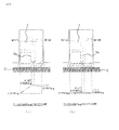
- FIG. 2 is an explanatory diagram showing the pressure distribution around the seal ring 3 in the first embodiment, where (a) is the pressure gradient of the sealing oil at a gas pressure of 0.30 MPa-g, and (b) is the gas pressure of 0.00 MPa-g.
- the pressure gradient of the sealing oil is shown for each hour.
- a minimum supply hydraulic pressure of 0.10 MPa-g can be secured even at an extremely low pressure close to a gas pressure of 0.00 MPa-g, such as during a trial operation, and a certain level or more.
- An outside pressure gradient can be secured.
- FIG. 3 is an explanatory diagram showing the pressure distribution around the seal ring 3 in the conventional apparatus, where (a) is the pressure gradient of the sealing oil at a gas pressure of 0.30 MPa-g, and (b) is the gas pressure of 0.00 MPa-g.
- the pressure gradient of the sealing oil is shown for each hour.
- the pressure gradient inside the machine is the same as the gas pressure of 0.30 MPa-g as shown in FIG.
- the outer pressure gradient is smaller than that when the gas pressure is 0.30 MPa-g. For this reason, in order to ensure the amount of sealing oil at this time, it is necessary to enlarge the clearance gap between the rotating shaft 2 and the seal ring 3. 2 and 3, a portion surrounded by a dotted line between the rotating shaft 2 and the seal ring 3 indicates a region where an oil film is formed with sealing oil.
- the differential pressure for adjusting the hydraulic pressure of the sealing oil from the sealing oil pump 7 to the seal ring 3 of the rotating electrical machine 1 in which hydrogen gas is sealed in addition to the first path for supplying the sealing oil from the sealing oil pump 7 via the differential pressure regulating valve 8, A second path for supplying the sealing oil from the sealing oil pump 7 via the relief valve 15 is provided, so that when operating at an extremely low pressure close to a gas pressure of 0.00 MPa-g, such as during a test operation.
- a gas pressure of 0.00 MPa-g such as during a test operation.
- Embodiment 2 the return oil of the differential pressure adjusting valve 8 and the relief valve 15 is configured to be returned to the vacuum chamber 5 through the separate sealed oil return pipes 9 and 10, but as shown in FIG.
- the return oil of the pressure adjusting valve 8 and the return oil of the relief valve 15 may return to the vacuum chamber 5 through the same sealed oil return pipe 18.
- This configuration has an advantage that the configuration is simple because only one sealed oil return pipe is required.
- 1 rotating electrical machine 1a sealed chamber, 2 rotating shaft, 3 seal ring, 4 Sealed oil drain pipe, 5 Vacuum tank, 6 Sealed oil supply pipe, 7 Sealed oil pump, 8 Differential pressure adjustment valve, 9 Sealed oil return pipe, 10 Sealed oil return pipe, 11 Oil level adjustment valve, 12 Gas discharge pipe, 13 vacuum pump, 14 discharge pipe, 15 relief valve, 16 Check valve, 17 Check valve, 18 Sealed oil return pipe.
Landscapes
- Engineering & Computer Science (AREA)
- General Engineering & Computer Science (AREA)
- Mechanical Engineering (AREA)
- Power Engineering (AREA)
- Motor Or Generator Cooling System (AREA)
- Motor Or Generator Frames (AREA)
- Sealing Using Fluids, Sealing Without Contact, And Removal Of Oil (AREA)
Abstract
Priority Applications (5)
| Application Number | Priority Date | Filing Date | Title |
|---|---|---|---|
| US15/303,701 US10069370B2 (en) | 2014-06-05 | 2014-06-05 | Seal oil supply device for dynamo-electric machine and seal oil supply method |
| PCT/JP2014/064936 WO2015186221A1 (fr) | 2014-06-05 | 2014-06-05 | Dispositif d'alimentation en huile de joint pour machine dynamoélectrique, et procédé d'alimentation en huile de joint |
| EP14893972.1A EP3154163B1 (fr) | 2014-06-05 | 2014-06-05 | Dispositif d'alimentation en huile de joint pour machine dynamoélectrique, et procédé d'alimentation en huile de joint |
| JP2016525629A JP6139790B2 (ja) | 2014-06-05 | 2014-06-05 | 回転電機の密封油供給装置及び密封油供給方法 |
| CN201480079581.0A CN106416005B (zh) | 2014-06-05 | 2014-06-05 | 旋转电机的密封油供给装置及密封油供给方法 |
Applications Claiming Priority (1)
| Application Number | Priority Date | Filing Date | Title |
|---|---|---|---|
| PCT/JP2014/064936 WO2015186221A1 (fr) | 2014-06-05 | 2014-06-05 | Dispositif d'alimentation en huile de joint pour machine dynamoélectrique, et procédé d'alimentation en huile de joint |
Publications (1)
| Publication Number | Publication Date |
|---|---|
| WO2015186221A1 true WO2015186221A1 (fr) | 2015-12-10 |
Family
ID=54766317
Family Applications (1)
| Application Number | Title | Priority Date | Filing Date |
|---|---|---|---|
| PCT/JP2014/064936 Ceased WO2015186221A1 (fr) | 2014-06-05 | 2014-06-05 | Dispositif d'alimentation en huile de joint pour machine dynamoélectrique, et procédé d'alimentation en huile de joint |
Country Status (5)
| Country | Link |
|---|---|
| US (1) | US10069370B2 (fr) |
| EP (1) | EP3154163B1 (fr) |
| JP (1) | JP6139790B2 (fr) |
| CN (1) | CN106416005B (fr) |
| WO (1) | WO2015186221A1 (fr) |
Families Citing this family (2)
| Publication number | Priority date | Publication date | Assignee | Title |
|---|---|---|---|---|
| CN107366749A (zh) * | 2017-08-28 | 2017-11-21 | 利辛县宝隆橡塑密封件有限责任公司 | 一种防尘密封 |
| CN112483357A (zh) * | 2020-11-11 | 2021-03-12 | 杭州国能汽轮工程有限公司 | 一种多功能供油系统 |
Citations (5)
| Publication number | Priority date | Publication date | Assignee | Title |
|---|---|---|---|---|
| JPS62145462U (fr) * | 1986-03-10 | 1987-09-14 | ||
| JPS6445472U (fr) * | 1987-09-11 | 1989-03-20 | ||
| JPH03155350A (ja) * | 1989-10-30 | 1991-07-03 | Westinghouse Electric Corp <We> | タービン発電機システム |
| JP2001028867A (ja) * | 1999-07-13 | 2001-01-30 | Mitsubishi Electric Corp | 回転電機の軸シール装置 |
| JP2004007876A (ja) * | 2002-05-31 | 2004-01-08 | Mitsubishi Electric Corp | 回転電機の密封油供給装置 |
Family Cites Families (9)
| Publication number | Priority date | Publication date | Assignee | Title |
|---|---|---|---|---|
| US3176996A (en) * | 1962-10-12 | 1965-04-06 | Barnett Leon Truman | Oil balanced shaft seal |
| US4029323A (en) * | 1972-04-11 | 1977-06-14 | Nippon Seiko Kabushiki Kaisha | Fluid pressure seal arrangement |
| US4005580A (en) * | 1975-06-12 | 1977-02-01 | Swearingen Judson S | Seal system and method |
| US4058320A (en) * | 1976-07-26 | 1977-11-15 | Westinghouse Electric Corporation | Generator seal oil supply system |
| JPS58148641A (ja) * | 1982-02-26 | 1983-09-03 | Toshiba Corp | タ−ビン発電機の軸封油供給装置 |
| US5474304A (en) * | 1994-06-27 | 1995-12-12 | General Electric Co. | Seal oil supply system using differential pressure accumulator |
| JPH0965600A (ja) * | 1995-08-28 | 1997-03-07 | Toshiba Corp | 回転電機の軸密封油系統のフロートトラップ槽 |
| US6116609A (en) * | 1997-12-17 | 2000-09-12 | A. W. Chesterton Company | Fluidic feedback pressure regulation system for a mechanical seal |
| JP4437752B2 (ja) * | 2005-02-16 | 2010-03-24 | 三菱電機株式会社 | 回転電機の密封油供給装置 |
-
2014
- 2014-06-05 JP JP2016525629A patent/JP6139790B2/ja not_active Expired - Fee Related
- 2014-06-05 US US15/303,701 patent/US10069370B2/en not_active Expired - Fee Related
- 2014-06-05 WO PCT/JP2014/064936 patent/WO2015186221A1/fr not_active Ceased
- 2014-06-05 EP EP14893972.1A patent/EP3154163B1/fr active Active
- 2014-06-05 CN CN201480079581.0A patent/CN106416005B/zh not_active Expired - Fee Related
Patent Citations (5)
| Publication number | Priority date | Publication date | Assignee | Title |
|---|---|---|---|---|
| JPS62145462U (fr) * | 1986-03-10 | 1987-09-14 | ||
| JPS6445472U (fr) * | 1987-09-11 | 1989-03-20 | ||
| JPH03155350A (ja) * | 1989-10-30 | 1991-07-03 | Westinghouse Electric Corp <We> | タービン発電機システム |
| JP2001028867A (ja) * | 1999-07-13 | 2001-01-30 | Mitsubishi Electric Corp | 回転電機の軸シール装置 |
| JP2004007876A (ja) * | 2002-05-31 | 2004-01-08 | Mitsubishi Electric Corp | 回転電機の密封油供給装置 |
Also Published As
| Publication number | Publication date |
|---|---|
| EP3154163B1 (fr) | 2020-02-19 |
| CN106416005A (zh) | 2017-02-15 |
| JP6139790B2 (ja) | 2017-05-31 |
| EP3154163A4 (fr) | 2018-01-10 |
| EP3154163A1 (fr) | 2017-04-12 |
| JPWO2015186221A1 (ja) | 2017-04-20 |
| US20170040862A1 (en) | 2017-02-09 |
| CN106416005B (zh) | 2019-02-15 |
| US10069370B2 (en) | 2018-09-04 |
Similar Documents
| Publication | Publication Date | Title |
|---|---|---|
| CN100582440C (zh) | 蒸汽轮机的可变压力控制冷却方案和推力控制装置 | |
| US10396618B2 (en) | Rotating electric machine with shaft-seal devices having partition plate | |
| US9429037B2 (en) | Turbine including seal air valve system | |
| JP2018503038A (ja) | 流体機械の軸封装置及び流体機械の軸の封止方法 | |
| AU2016280924B2 (en) | Expansion turbine device | |
| JP6139790B2 (ja) | 回転電機の密封油供給装置及び密封油供給方法 | |
| JP5969110B2 (ja) | 蒸気タービンシステムおよび蒸気タービンの始動法 | |
| US20170191486A1 (en) | Fluid energy machine having a tandem dry gas seal | |
| JP6228377B2 (ja) | 蒸気タービン用シャフトシールシステム | |
| AU2016280925B2 (en) | Expansion turbine device | |
| AU2013258038B2 (en) | Pressure equalizer | |
| US9506373B2 (en) | Steam turbine arrangement of a three casing supercritical steam turbine | |
| EP3095987A1 (fr) | Système et procédé d'alimentation en combustible liquide d'une turbine à gaz | |
| JPWO2017154084A1 (ja) | 軸封装置付き回転電機 | |
| JP6061795B2 (ja) | 回転電機の密封油供給装置 | |
| CN106460569B (zh) | 用于使蒸汽膨胀的装置和控制所述装置的方法 | |
| JP2013221510A (ja) | 蒸気タービン用シャフトシールシステム | |
| JP2016197959A (ja) | 回転電機の密封油装置 | |
| GB2483714A (en) | Gas turbine engine bearing housing sealing | |
| JP4437752B2 (ja) | 回転電機の密封油供給装置 |
Legal Events
| Date | Code | Title | Description |
|---|---|---|---|
| 121 | Ep: the epo has been informed by wipo that ep was designated in this application |
Ref document number: 14893972 Country of ref document: EP Kind code of ref document: A1 |
|
| ENP | Entry into the national phase |
Ref document number: 2016525629 Country of ref document: JP Kind code of ref document: A |
|
| WWE | Wipo information: entry into national phase |
Ref document number: 15303701 Country of ref document: US |
|
| REEP | Request for entry into the european phase |
Ref document number: 2014893972 Country of ref document: EP |
|
| WWE | Wipo information: entry into national phase |
Ref document number: 2014893972 Country of ref document: EP |
|
| NENP | Non-entry into the national phase |
Ref country code: DE |