WO2015186692A1 - 医療機器 - Google Patents
医療機器 Download PDFInfo
- Publication number
- WO2015186692A1 WO2015186692A1 PCT/JP2015/065869 JP2015065869W WO2015186692A1 WO 2015186692 A1 WO2015186692 A1 WO 2015186692A1 JP 2015065869 W JP2015065869 W JP 2015065869W WO 2015186692 A1 WO2015186692 A1 WO 2015186692A1
- Authority
- WO
- WIPO (PCT)
- Prior art keywords
- resin
- region
- medical device
- catheter
- tube
- Prior art date
- Legal status (The legal status is an assumption and is not a legal conclusion. Google has not performed a legal analysis and makes no representation as to the accuracy of the status listed.)
- Ceased
Links
Images




Classifications
-
- A—HUMAN NECESSITIES
- A61—MEDICAL OR VETERINARY SCIENCE; HYGIENE
- A61M—DEVICES FOR INTRODUCING MEDIA INTO, OR ONTO, THE BODY; DEVICES FOR TRANSDUCING BODY MEDIA OR FOR TAKING MEDIA FROM THE BODY; DEVICES FOR PRODUCING OR ENDING SLEEP OR STUPOR
- A61M25/00—Catheters; Hollow probes
- A61M25/0043—Catheters; Hollow probes characterised by structural features
- A61M25/005—Catheters; Hollow probes characterised by structural features with embedded materials for reinforcement, e.g. wires, coils, braids
- A61M25/0053—Catheters; Hollow probes characterised by structural features with embedded materials for reinforcement, e.g. wires, coils, braids having a variable stiffness along the longitudinal axis, e.g. by varying the pitch of the coil or braid
-
- A—HUMAN NECESSITIES
- A61—MEDICAL OR VETERINARY SCIENCE; HYGIENE
- A61M—DEVICES FOR INTRODUCING MEDIA INTO, OR ONTO, THE BODY; DEVICES FOR TRANSDUCING BODY MEDIA OR FOR TAKING MEDIA FROM THE BODY; DEVICES FOR PRODUCING OR ENDING SLEEP OR STUPOR
- A61M25/00—Catheters; Hollow probes
- A61M25/0043—Catheters; Hollow probes characterised by structural features
- A61M25/0045—Catheters; Hollow probes characterised by structural features multi-layered, e.g. coated
-
- A—HUMAN NECESSITIES
- A61—MEDICAL OR VETERINARY SCIENCE; HYGIENE
- A61M—DEVICES FOR INTRODUCING MEDIA INTO, OR ONTO, THE BODY; DEVICES FOR TRANSDUCING BODY MEDIA OR FOR TAKING MEDIA FROM THE BODY; DEVICES FOR PRODUCING OR ENDING SLEEP OR STUPOR
- A61M25/00—Catheters; Hollow probes
- A61M25/0043—Catheters; Hollow probes characterised by structural features
- A61M25/0054—Catheters; Hollow probes characterised by structural features with regions for increasing flexibility
-
- A—HUMAN NECESSITIES
- A61—MEDICAL OR VETERINARY SCIENCE; HYGIENE
- A61M—DEVICES FOR INTRODUCING MEDIA INTO, OR ONTO, THE BODY; DEVICES FOR TRANSDUCING BODY MEDIA OR FOR TAKING MEDIA FROM THE BODY; DEVICES FOR PRODUCING OR ENDING SLEEP OR STUPOR
- A61M25/00—Catheters; Hollow probes
- A61M25/0043—Catheters; Hollow probes characterised by structural features
- A61M2025/0063—Catheters; Hollow probes characterised by structural features having means, e.g. stylets, mandrils, rods or wires to reinforce or adjust temporarily the stiffness, column strength or pushability of catheters which are already inserted into the human body
- A61M2025/0064—Catheters; Hollow probes characterised by structural features having means, e.g. stylets, mandrils, rods or wires to reinforce or adjust temporarily the stiffness, column strength or pushability of catheters which are already inserted into the human body which become stiffer or softer when heated
-
- A—HUMAN NECESSITIES
- A61—MEDICAL OR VETERINARY SCIENCE; HYGIENE
- A61M—DEVICES FOR INTRODUCING MEDIA INTO, OR ONTO, THE BODY; DEVICES FOR TRANSDUCING BODY MEDIA OR FOR TAKING MEDIA FROM THE BODY; DEVICES FOR PRODUCING OR ENDING SLEEP OR STUPOR
- A61M2205/00—General characteristics of the apparatus
- A61M2205/02—General characteristics of the apparatus characterised by a particular materials
-
- A—HUMAN NECESSITIES
- A61—MEDICAL OR VETERINARY SCIENCE; HYGIENE
- A61M—DEVICES FOR INTRODUCING MEDIA INTO, OR ONTO, THE BODY; DEVICES FOR TRANSDUCING BODY MEDIA OR FOR TAKING MEDIA FROM THE BODY; DEVICES FOR PRODUCING OR ENDING SLEEP OR STUPOR
- A61M25/00—Catheters; Hollow probes
- A61M25/0097—Catheters; Hollow probes characterised by the hub
Definitions
- the present invention relates to a medical device.
- This application claims priority based on Japanese Patent Application Nos. 2014-114889 and 2014-114891 filed in Japan on June 3, 2014, the contents of which are incorporated herein by reference.
- a catheter that can be inserted into a body cavity such as a blood vessel.
- a catheter is inserted into a body cavity by a technique called over-the-wire using a guide wire.
- the guide wire Prior to the desired branch path, the guide wire is placed in a bent state, and the catheter is covered from the proximal end side and pushed along the guide wire. Thereby, a branch path can be selected.
- the catheter In order to select a desired branch path in the branch of the body cavity and to advance in the insertion direction, the catheter is generally formed to be reasonably flexible. For this reason, the catheter is generally long and includes a flexible resin tube.
- a catheter provided with a resin tube that can be applied to a thin body cavity with many branches and bends in a complicated manner, such as a blood vessel terminal region, etc., so that the branch can be selected satisfactorily.
- the catheter described in Patent Document 1 (hereinafter, also referred to as Conventional Technology 1) includes a resin outer layer having different hardness between the proximal end portion and the distal end portion, that is, flexibility.
- a resin tube that is an outer resin layer is configured by using four types of polyetheresteramide elastomers having different Shore D hardnesses.
- Patent Document 1 describes that the hardness of the four types of polyetheresteramide elastomer is proportional to the weight ratio of the hard segment of the polyetheresteramide elastomer.
- the long medical devices such as the catheter and the puncture needle for the endoscope are common in that they are flexible and have a long sheath and a hub on the hand side.
- the sheath has one or more inner holes (lumens) extending from the distal end to the proximal end, and various articles such as a medical solution, a contrast medium, a guide wire, a puncture needle, and other medical devices are supplied into the inner hole. Is done.
- a single tube or a double tube is used depending on the type of medical device.
- the hub is generally made of a material that is thicker and harder than the sheath so that the user's handling is good.
- the hub is hollow and communicates with the inner hole of the sheath, and a connector for attaching a syringe is generally provided at the proximal end of the hub.
- Patent Document 2 discloses a medical device (catheter) including a long sheath (catheter body) composed of a double tube body and a hub provided at the proximal end of the sheath. ) Is described. The proximal end portion of the sheath is inserted and fixed inside the hub, and the vicinity of the fixed portion is held by a kink protector (protector).
- the protector is a cylindrical protective member that prevents the inner end of the sheath from being bent (kink) by bending the proximal end of the sheath, and is provided at the distal end of the hub.
- the protector is also called a connector cover or a strain relief, and has sufficient bending rigidity and hardness.
- the sheath is made mainly of a resin material such as polyurethane resin or polyamide resin. In order to improve visibility when placed on an instrument table or operating table, the sheath is generally opaque and colored in various colors.
- Patent Document 3 and Patent Document 4 describe a medical device in which a sheath is made transparent so that a drug solution passing through the inside can be visually confirmed from the outside.
- the catheter advances in the body cavity so as to be pushed in the forward direction along the guide wire in the non-branching region or the branching passage having a relatively large inner diameter and a gentle bending angle. Therefore, it is preferable that the catheter has an appropriate rigidity in addition to the slidability with respect to the guide wire to such an extent that good pushability is exhibited including the distal end portion. That is, the resin tube of the catheter is required to have an appropriate rigidity so as to have good pushability.
- the tip of the resin tube is flexible in order to obtain good branch selectivity. Accordingly, the catheter can be inserted into a desired branch path while the bending state of the guide wire placed in the branch path is maintained in the body cavity.
- the distal end is stiff, when the catheter is pushed along the guide wire, the distal end portion of the guide wire cannot be placed in a bent state in a desired branch path, and branch selectivity may be poor. is there.
- a guiding catheter (parent catheter) or an endoscope is placed on the subject, and the medical device is connected from the connector or the hand operation unit at the proximal end thereof. Is generally inserted.
- the hub of the medical device may reach the vicinity of the connector of the guiding catheter or the proximal operation portion of the endoscope (hereinafter sometimes referred to as a body cavity introduction port).
- the hub is made of a transparent resin material, and there is one in which it is possible to visually confirm that the tip of the syringe filled with the chemical solution is normally attached to the hub.
- the protector is formed of an opaque resin material, thereby ensuring the visibility of the medical device in a state of being placed on the instrument table or the operating table.
- the present invention has been made in view of the above problems. That is, the present invention provides a medical device including a resin tube with good branch selectivity while maintaining good pushability in a complicatedly bent body cavity or an extremely thin body cavity such as a blood vessel end region. And Furthermore, while providing the above-mentioned excellent pushability and branching selectivity, it is possible to provide a medical device capable of visually confirming the internal state of the inner hole of the sheath even when the sheath is inserted sufficiently deep into the body cavity. .
- the present invention provides the following medical devices (1) to (19).
- a medical device having a medical device body inserted into a body cavity, The medical device body has a long resin tube, The resin tube includes a first region including an insertion distal end portion and a second region including a proximal end portion, A medical device in which the first region is more flexible than the second region.
- the first region is composed of a first resin member
- the second region is composed of a resin member different from the first resin member
- the difference X between the resin hardness of the first resin member measured at room temperature and the resin hardness of the first resin member measured after standing for a predetermined time in a temperature environment of 38 ° C. was measured at room temperature.
- the first resin member and the second resin member are (I) The resin hardness of the first resin member measured at normal temperature is not less than the resin hardness of the second resin member, (II) Any one of (2) to (4), wherein the resin hardness of the first resin member measured after being left in a temperature environment of 38 ° C. for a predetermined time is less than the resin hardness of the second resin member Medical device as described in.
- a metal protective layer formed by braiding a wire is provided in at least the second region of the resin tube, and an opening area ratio of the metal protective layer at the proximal end of the resin tube is 50.
- the metal protective layer is provided in the first region and the second region of the resin pipe, The medical device according to (11), wherein the opening area ratio of the metal protective layer at the proximal end of the second region is larger than the opening area ratio of the insertion distal end of the first region. .
- the medical device is provided with a hollow hub provided at a proximal end side end of the resin tube so as to communicate with an inner hole of the resin tube, and provided at a distal end portion of the hub.
- An extension region extending to the tip side of the protector in the proximal end side end portion of the resin pipe has visible light permeability, and the tip side of the resin tube is closer to the tip side than the extension region.
- the medical device according to (14), wherein the distal end portion positioned has visible light impermeability.
- the resin tube outer diameter is the same diameter across the extension region and the tip portion of the resin tube, and the tip portion of the resin tube faces the distal end of the resin tube.
- a hydrophilic coat layer is provided on the outer surface of the resin tube from the insertion tip side end to the extension region, and the hydrophilic coat layer terminates in the middle of the extension region.
- the present invention includes a resin tube whose tip portion is softer than the base end portion under predetermined conditions.
- the medical device of the present invention has good branch selectivity while maintaining good pushability in a complicatedly bent body cavity or an extremely thin body cavity such as a blood vessel terminal region.
- the internal state of the inner hole of the catheter body can be visually confirmed through the protector even when the sheath (catheter body) is inserted sufficiently deep into the body cavity. Is possible. Thereby, even when the distal end of the catheter body reaches the vicinity of the target biological tissue, it is possible to quickly know the poor injection of the chemical solution and the occurrence of reverse blood.
- 1 is an overall view of a catheter in a first embodiment of the present invention. It is a longitudinal cross-sectional view of the front-end
- distal end means an insertion tip of the medical device main body
- distal end portion means a predetermined length region including the distal end
- proximal end portion refers to a predetermined length region including an end portion (proximal end) on the proximal end side of the medical device main body.
- the axis means the central axis in the longitudinal direction of the medical device body.
- the “longitudinal section” of a medical device refers to a cross section obtained by cutting a medical device (a catheter in the embodiment) in parallel to the longitudinal direction through the axis.
- “Resin hardness” means a physical property value of the resin member itself.
- the resin hardness of the first resin member or the second resin member can be measured based on a known test method such as Shore hardness.
- the resin hardness when the first resin member or the second resin member contains an additive other than a resin such as a contrast medium or an optional filler, the first resin member or It means the resin hardness of the second resin member.
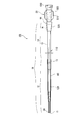
- FIG. 1 is an overall view of a catheter 100 that is a medical device according to the first embodiment of the present invention.
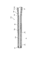
- FIG. 2 is a longitudinal sectional view of the distal end portion of the catheter 100.
- FIG. 3 is an explanatory diagram of the distal end portion of the catheter main body 110 according to the first embodiment.
- FIG. 3 is an enlarged view of the tip shown in FIG.
- FIG. 3 is a cross-sectional view of the outer tube 10 and the outer layer 60, and a side view of the inner tube 20, the marker 30, and the metal protective layer 40.
- the medical device (catheter 100) is long and flexible, and has a medical device body (catheter body 110) that is inserted into a body cavity.
- the medical device main body (catheter main body 110) has a long resin tube (outer tube 10).
- the resin tube (outer tube 10) is composed of a first region 12 composed of the first resin member and a second resin member which is a resin member different from the first resin member, and is proximal to the first region 12. And a second region 14 located in the region.
- the difference X between the resin hardness of the first resin member measured at room temperature and the resin hardness of the first resin member measured after being left for a predetermined time in a temperature environment of 38 ° C. is:
- the difference Y between the resin hardness of the second resin member measured at normal temperature and the resin hardness of the second resin member measured after being allowed to stand for a predetermined time in a temperature environment of 38 ° C. is configured.
- the outer tube 10 including the first region 12 can have rigidity enough to exhibit good pushability when inserted into a body cavity.
- body temperature that is, a temperature of about 38 ° C.
- the first region 12 of the outer tube 10 is remarkably softened, and the distal end portion of the catheter body 110 is softened.
- Branch selectivity is improved.
- first resin member and the second resin member are different resin members, they can exhibit different temperature characteristics as described above.
- the difference is that the first resin member and the second resin member are each composed of one different kind of resin, one is a composition comprising one resin and the other comprising a plurality of different kinds of resins, Embodiments in which each is a composition comprising a plurality of different resins are included.
- the first resin member and the second resin member may be the same resin composition in which two or more resin components are contained in each other and may have different component ratios.
- the catheter 100 when the catheter 100 enters the blood vessel from a predetermined location and enters a desired living tissue, if a branch selection is difficult to reach, a predetermined time is required for the branch selection operation. .
- the resin hardness of the first resin constituting the first region 12 is significantly reduced as compared with the resin hardness in the normal temperature environment during the operation time. That is, the catheter body 110 is softened and the branching selectivity of the catheter 100 is improved.
- a medical device (hereinafter also referred to as a catheter 100) according to the present embodiment includes a medical device main body (hereinafter also referred to as a catheter main body 110).
- the catheter body 110 is long and flexible and is inserted into a body cavity.
- the catheter body 110 includes an outer tube 10 that is a long resin tube and an inner tube 20 that is laminated on the inner peripheral side of the outer tube 10.
- a metal protective layer 40 is provided on the outer periphery of the inner tube 20 by winding the wires 41 at a predetermined interval.
- Catheter 100 is a suitable example that is an intravascular catheter used by being inserted into a blood vessel.
- the catheter 100 according to this embodiment is, for example, an inactive catheter. That is, the catheter 100 can be used as an inactive catheter including the catheter body 110 that is inserted into the body cavity by a technique called over-the-wire using a guide wire, and does not have an operation mechanism that bends the distal end portion. As described above, the catheter 100 has good followability with respect to the guide wire because the first region 12 is more flexible than the second region 14 when a predetermined time has passed in the body cavity.
- the outer tube 10 is a long and hollow resin tube.
- the outer tube 10 includes the first region 12 and the second region 14 as described above.
- the first region 12 constitutes the tip (distal end) of the outer tube 10.
- the second region 14 constitutes the proximal end (proximal end) of the outer tube 10.
- the distal end portion of the outer tube 10 is a predetermined region including the distal end of the outer tube 10 on the distal side of the catheter body 110 or a predetermined region near the distal end not including the distal end.
- the proximal end portion of the outer tube 10 is a region located on the proximal side of the catheter body 110 with respect to the distal end portion, and the proximal end of the outer tube 10 on the proximal side of the catheter body 110. Or a predetermined region near the base end that does not include the base end.
- the first region 12 that is the tip of the outer tube 10 is a predetermined region including the tip of the outer tube 10 on the distal side of the catheter body 110. is there.
- the distal end of the first region 12 constitutes the distal end of the resin tube (outer tube 10). Therefore, when the branch selection operation requires a significant amount of time, the softening of the first region 12 contributes well to the softening of the distal end portion of the catheter body 110.
- the first region 12 is composed of a first resin member.
- the first resin member includes one or more resins. That is, the first resin member may be composed of only the first resin, or may be a resin composition in which the first resin and one or more other resins other than the first resin are blended.
- the second region 14 is composed of a second resin member.
- the second resin member includes one or more resins. That is, the second resin member may be composed of only the second resin, or may be a resin composition in which the second resin and one or more other resins other than the second resin are blended. The first resin and the second resin are different resins.
- region 14 contain an arbitrary compounding agent suitably as components other than resin.
- the first region 12 and / or the second region 14 may contain an appropriate amount of contrast agent.
- thermoplastic polymers examples include polyurethane (PU) resin, polyimide (PI) resin, polyamideimide (PAI) resin, polyethylene terephthalate (PET) resin, polyethylene (PE) resin, and polyamide (PA) resin.
- PU polyurethane
- PI polyimide
- PAI polyamideimide
- PET polyethylene terephthalate
- PA polyamide
- Nylon elastomer resin ethylene-vinyl acetate resin
- EVA ethylene-vinyl acetate resin
- PVC polyvinyl chloride
- PP polypropylene
- thermoplastic elastomer is a concept that includes a polymer alloy (polymer blend, block copolymerization, graft copolymerization, random copolymerization, etc.), a material softened with a plasticizer, and a mixture thereof. is there.
- the elastomer include urethane elastomers, amide elastomers (nylon elastomers), styrene elastomers, olefin elastomers, and vinyl chloride elastomers.
- the urethane elastomer is, for example, a thermoplastic polyurethane elastomer.
- the amide-based elastomer include thermoplastic polyamide elastomers and thermoplastic polyether block amide copolymers.
- the resin hardness of the first resin member and the second resin member is not particularly limited, but is preferably a resin hardness that can impart good pushability to the outer tube 10 in a room temperature environment.
- the normal temperature is not a strictly specified temperature, but is, for example, about 23 ° C. ⁇ 2 ° C.
- the difference between the resin hardness of the first resin member measured in a normal temperature environment and the resin hardness of the first resin member measured after being left standing in a temperature environment of 38 ° C. for a predetermined time is defined as a difference X.
- the difference Y is the difference between the resin hardness of the second resin member measured in a normal temperature environment and the resin hardness of the second resin member measured after being left for a predetermined time in a temperature environment of 38 ° C.
- Difference X is greater than difference Y.
- the Shore hardness (hardness A-1) measured in a normal temperature environment according to ISO 868 is measured using a first test piece made of a first resin member cut to an appropriate size.
- the first test piece is immersed in a thermostatic bath kept at 38 ° C. for a predetermined time, and the Shore hardness (hardness A-2) measured according to ISO868 is measured.
- the difference X is the value obtained by subtracting (hardness A-2) from (hardness A-1).
- (hardness B-1) is obtained in the same manner as (hardness A-1) using a second test piece made of a second resin member cut to the same size as the first test piece.
- Hardness B-2) is obtained by the same method as for hardness A-2), and can be obtained by subtracting (hardness B-2) from (hardness B-1).
- the method for measuring the Shore hardness of the first resin member and the second resin member described above appropriately measures the resin hardness of the first resin member and the second resin member in a normal temperature environment or a body temperature environment in the present embodiment. To be referenced.
- the difference X and the difference Y as the resin hardness are described, but the difference in the first and second regions is not limited to the resin hardness.
- a resin member constituting the outer tube in the distal end region of the catheter is used as a test piece, and the load is measured by pressing the distal end of the catheter against the load measuring device from a vertical direction under a predetermined condition.
- the difference XI or the difference YI can be obtained from the difference between the load of the test piece measured in the normal temperature environment and the load of the test piece measured using the test piece after being left in the body temperature environment for a predetermined time.
- the predetermined time of leaving in a temperature environment of 38 ° C. is not particularly limited, and may be adjusted according to the thickness of the test piece. For example, it can be left in a temperature environment of 38 ° C. until the temperature of the test piece itself reaches 38 ° C.
- the relationship between the first resin member and the second resin member is adjusted, for example, such that the ratio of the resin hardness of the first resin at normal temperature to the difference X is larger than the ratio of the resin hardness of the second resin at normal temperature to the difference Y. May be.
- the first resin member includes 50% or more of the first resin
- the second resin member includes 50% or more of the second resin which is a resin different from the first resin.
- More preferable examples include that the first resin is a thermoplastic polyurethane resin and the second resin is a polyamide resin. Such a combination can satisfactorily solve the problems of the present invention and realize good pushability and good branch selectivity.
- thermoplastic polyurethane elastomer can be selected as the first resin
- a polyamide elastomer nylon elastomer
- these may be blended with other resins, respectively, to form the first resin member and the second resin member.
- the resin material of the first resin member may be made of only a thermoplastic polyurethane elastomer
- the resin material of the second resin member may be made of a polyamide elastomer.
- thermoplastic polyurethane elastomer as the first resin include “Pellethane” manufactured by Dow Chemical Japan Co., Ltd., “Tecocene” and “Tecoflex” manufactured by Lubrizol. Yes, but not limited to this.
- Specific examples of the polyamide-based elastomer that is the second resin include, but are not limited to, “Pebax” provided by Tokyo Materials Co., Ltd., which is a commercial product.
- the first resin member and the second resin member may be configured as (I) and (II) below.
- the resin hardness of the first resin member measured at normal temperature is equal to or higher than the resin hardness of the second resin member.
- the resin hardness of the first resin member measured after being left in a temperature environment of 38 ° C. for a predetermined time is less than the resin hardness of the second resin member.
- the first region 12 made of the first resin member is harder than the second region 14 made of the second resin member when the body cavity enters or before the predetermined time has passed and the catheter 100 is made. Contributes to good pushability of the tip of the.
- the first region 12 becomes softer than the second region 14 when the operation time is prolonged in the body cavity and a predetermined time has elapsed.
- the catheter 100 can exhibit good branching selectivity at the distal end portion including the first region 12 while maintaining good pushability at the proximal end portion including the second region 14.
- the first region 12 in the present embodiment is a tip provided locally at the tip of the outer tube 10.
- the dimension of the first region 12 in the axial direction is not less than 5 mm and not more than 15 mm, more preferably not less than 8 mm and not more than 12 mm.
- good branching selectivity is imparted to the catheter 100. At the same time, the loss of pushability is sufficiently avoided.
- the second region 14 in the present embodiment is preferably configured so that the rigidity continuously increases from the distal side to the proximal side.
- the second region 14 includes a resin member 14a, a resin member 14b, a resin member 14c, a resin member 14d, and a resin member 14e that are continuously arranged in this order from the distal side.
- the resin member 14a, the resin member 14b, the resin member 14c, the resin member 14d, and the resin member 14e are located on the inner peripheral side of the outer layer 60, and their boundaries are indicated by broken lines.
- the second resin member to be compared with the first resin member is related to various features of the present invention. It is a resin member disposed closest to at least the first resin member among the plurality of resin members constituting the two regions 14.
- the magnitude relationship of the resin hardness (Shore hardness) at normal temperature of each resin member constituting the second region 14 is resin member 14a ⁇ resin member 14b ⁇ resin member 14c ⁇ resin member 14d ⁇ resin member 14e.
- resin member 14a, the resin member 14b, the resin member 14c, the resin member 14d, and the resin member 14e are all the same type of resin whose hardness is adjusted (for example, all are polyamide-based elastomers), 38
- the resin hardness (Shore hardness) at 0 ° C. is also the same as the tendency of the magnitude relation of the resin hardness at normal temperature described above.
- the second region 14 may be formed of one resin member whose hardness does not change.
- the catheter 100 is provided with a marker 30 for confirming the body cavity intrusion position of the catheter main body 110 with X-rays.
- the marker 30 has a ring shape including a material that does not transmit radiation such as X-rays.
- the marker 30 is made of a metal material such as platinum.
- the marker 30 is provided around the inner tube 20.
- the marker 30 in the present embodiment is provided at the distal end portion of the catheter 100 and includes a radiopaque metallic material. As shown in FIGS. 2 and 3, the marker 30 is covered with the first resin member. The dimension in the axial direction of the first region 12 exceeds the width dimension of the marker 30, and the entire marker 30 attached to the inner tube 20 can be covered from the outer peripheral side. The first region 12 can accurately confirm the bent state of the distal end of the catheter 100 by providing the marker 30 in the bent region of the distal end of the catheter 100.
- the catheter body 110 has an inner tube 20 stacked on the inner periphery of the resin tube (outer tube 10).
- the inner tube 20 is formed of a tubular resin material.
- An inner hole 120 is formed at the center of the inner tube 20 (see FIG. 2).
- the inner hole 120 is formed from a proximal end portion to a distal end portion of the catheter body 110 called a so-called main lumen.
- a treatment instrument or a guide wire is appropriately inserted into the inner hole 120, and liquids such as various drugs and contrast agents to be injected into the body cavity can be circulated, or a liquid such as blood can be sucked from the body.
- the distal end of the inner tube 20 is preferably located at the same position as the distal end of the first region 12 in the axial direction.
- the same position means substantially the same position in the axial direction, and includes the extent that it can be visually confirmed that the position is the same even if it is slightly shifted in measurement.
- the distance between the tip of the inner tube 20 and the tip of the first region 12 is about 0 mm ⁇ 1 mm in the axial direction.
- the treatment of sliding the inner hole 120 is performed. It is possible to prevent the first region 12 from coming into close contact with the instrument or guide wire. From this viewpoint, it is preferable that the inner tube 20 is made of a material having good sliding properties with respect to a medical instrument such as a fluorine-based thermoplastic polymer material or a guide wire.
- the material of the inner tube 20 is preferably, for example, a fluorine-based thermoplastic polymer material.
- the fluorine-based thermoplastic polymer material is, for example, polytetrafluoroethylene (PTFE), polyvinylidene fluoride (PVDF), or perfluoroalkoxy fluororesin (PFA).
- PTFE polytetrafluoroethylene
- PVDF polyvinylidene fluoride
- PFA perfluoroalkoxy fluororesin
- the inner tube 20 in the present embodiment is composed of a third resin member that is a resin member different from the first resin member and the second resin member.
- a third resin member one having a resin hardness exceeding the resin hardness of the first resin member and the second resin member in a normal temperature and a temperature environment of 38 ° C. can be selected.
- the present invention does not exclude that the outer tube 10 and the inner tube 20 are made of the same type of resin member.
- the present invention does not exclude that the third resin member constituting the inner tube 20 and either the first resin member or the second resin member are the same type of resin.
- the catheter 100 may have a sub-lumen formed inside the outer tube 10 as a modified example not shown.
- a hollow resin tube having an inner diameter smaller than the inner diameter of the inner hole 120 is embedded in the outer tube 10, and one or more subroutines communicating from the proximal side to the distal side are provided in the outer tube 10. Also good.
- an operation line for operating the direction of the distal end of the catheter 100 can be inserted into the sub-lumen.
- the catheter 100 has a metal protective layer 40 provided on the inner peripheral side or inside of the resin tube (outer tube 10).
- being provided on the inner peripheral side means that the metal protective layer 40 is provided in direct or indirect contact with the inner peripheral surface of the outer tube 10.
- being provided inside means that at least a part of the metal protective layer 40 is provided in a state of being bitten in the thickness direction of the outer tube 10.
- FIG. 2 a mode in which the metal protective layer 40 bites in the thickness direction from the inner peripheral surface side of the outer tube 10 is shown.
- the tip of the metal protective layer 40 is located closer to the proximal side than the tip of the first region 12 in the axial direction. For this reason, it is prevented that the front-end
- the wire 41 is illustrated in a linear shape ignoring the thickness for simplification of illustration.
- the metal protective layer 40 in this embodiment is attached to the inner tube 20 and the outer tube 10, for example.
- the metal protective layer 40 is configured by winding a wire 41 around the inner tube 20.
- FIG. 2 illustrates a cross section of the wires 41 arranged from the proximal side to the distal side on the outer periphery of the inner tube 20.
- a plurality of (for example, eight) wires 41 are wound around the outer periphery of the inner tube 20 in a right spiral, and a plurality of (for example, eight) wires 41 are wound around the outer periphery in a left spiral.
- a so-called blade-shaped metal protective layer 40 in which right-handed and left-handed wires 41 are knitted together is illustrated.
- the pitch of the plurality of wires 41 wound in the same direction is, for example, about 200 ⁇ m. Further, the pitch may be changed from the proximal side to the distal side.
- the pitch interval in the first region 12 is smaller than the pitch interval in the second region and other regions.
- the wire pitch interval 42 is gradually narrowed from the second region to the first region. Thereby, the flexibility of the distal end portion of the catheter 100 can be further improved.
- the metal protective layer 40 can be appropriately changed to a coiled form in which one or more wires 41 are wound in one direction.
- a metal is preferably used as a material of the wire 41 constituting the metal protective layer 40.
- the material is not limited to this example, and is not limited to this example, and is made of a material having higher rigidity and elasticity than the inner tube 20 and the outer tube 10.
- Other materials for example, resin
- tungsten, stainless steel (SUS), nickel titanium alloy, steel, titanium, or copper alloy can be used as the metal material of the wire 41.
- the outer layer 60 is provided on the outer peripheral side of the outer tube 10.
- the outer layer 60 in the present embodiment constitutes the outermost layer of the catheter body 110.
- the outer layer 60 can be made of, for example, a hydrophilic material.
- the outer layer 60 may be formed only in a region extending over a part of the distal end portion of the catheter main body 110, or may be formed over the entire length of the catheter 100.
- the outer layer 60 has hydrophilicity, for example, by molding with a hydrophilic resin material such as polyvinyl alcohol (PVA) or polyvinyl pyrrolidone.
- PVA polyvinyl alcohol
- PVC polyvinyl pyrrolidone
- an arbitrary surface treatment may be performed on the outer peripheral surface of the outer tube 10 to add a desired property.
- the outer peripheral surface of the outer tube 10 may be subjected to water immersion treatment to add lubricity to the outer surface of the outer tube 10.
- a grip 50 is provided adjacent to the proximal end of the catheter body 110.
- the holding part 50 has a connecting part 530 for inserting an injector (syringe) (not shown) from the rear.
- a thread groove is formed on the outer periphery of the connecting portion 530 so that the syringe can be fixed.
- the connecting part 530 is detachable.
- a hub 500 is provided at the center of the grip portion 50.
- a hollow penetrating in the axial direction is formed inside the hub 500, and the inner tube 20 and the outer tube 10 extend (not shown).
- the hub 500 has two wings 510 that extend outward from the outer peripheral surface and face each other via an axis. By rotating the wing 510 around the axis, a torque operation for rotating the entire catheter body 110 is possible, and the direction of the distal end of the catheter body 110 that has entered the body cavity can be adjusted.
- a protector 520 is provided on the distal end side of the hub 500 and covers the proximal ends of the inner tube 20 and the outer tube 10 that enter the hub 500.
- the outer diameter of the catheter body 110 is configured as follows, for example. That is, as shown in FIG. 1, the outer diameter 550 of the first region 12 is about 570 ⁇ m or more and 770 ⁇ m or less (for example, 670 ⁇ m), and the outer diameter of the resin member 14 a constituting the tip of the second region 14 is outside the first region 12.
- the outer diameter 552 of the front end of the resin member 14c is equal to or greater than the diameter, and is about 700 ⁇ m to 900 ⁇ m (for example, 800 ⁇ m).
- the outer diameter 554 of the front end of the resin member 14d is about 770 ⁇ m to about 970 ⁇ m (for example, 870 ⁇ m).
- the outer diameter 556 is about 870 ⁇ m or more and 1070 ⁇ m or less (for example, 970 ⁇ m). That is, the maximum outer diameter of the catheter body 110 is around 1 mm in diameter, and preferably 1 mm or less. Thereby, the catheter main body 110 of the present embodiment can be inserted into a blood vessel such as a celiac artery.
- the outer diameters of the first region 12, the region constituted by the resin member 14a, and the region constituted by the resin member 14e are uniform.
- the outer diameter of the region constituted by the resin members 14b to 14d has a diameter-expanded portion that increases in diameter from the distal end to the proximal end in the intermediate portion in the axial direction.
- the distance 540 from the tip of the marker 30 to the tip of the catheter body 110 is about 0.5 mm to 1 mm, and from the tip of the marker 30 to the proximal end of the first region 12.
- the distance 560 is about 5 mm or more and 15 mm or less (for example, 10 mm)
- the distance 580 from the distal end to the base end of the region constituted by the resin member 14a is about 15 mm or more and 25 mm or less (for example, 20 mm).
- the diameter 558 of the inner hole 120 at the distal end of the catheter body 110 is about 400 ⁇ m or more and 600 ⁇ m or less (for example, 500 ⁇ m) in a range smaller than the outer diameter 550 of the first region 12.
- a guide wire having a diameter of about 460 ⁇ m can be inserted into the inner hole 120.
- the diameter of the inner hole 120 may be uniform from the distal end to the proximal end, or the diameter may be increased in proportion to the expansion of the outer diameter of the outer tube 10.
- the overall length of the catheter body 110 is 1,250 mm, for example.
- the inner tube 20 can have a thickness of about 10 ⁇ m to 50 ⁇ m, and the outer tube 10 can have a thickness of about 30 ⁇ m to 160 ⁇ m.
- the thickness of the inner tube 20 and the thickness of the outer tube 10 in the above ranges are suitable, and it is a preferred embodiment that the thickness of the outer tube 10 is larger than the thickness of the inner tube 20.
- a core material having a peripheral surface matching the shape of the inner hole 120 of the catheter body 110 is prepared, and the inner tube 20 is formed along the outer periphery of the core material.
- the wire 41 is wound around the outer peripheral surface of the inner tube 20 to form the metal protective layer 40.
- the wire 41 may be wound at a constant pitch with a commercially available device or the like. Of course, the pitch may be changed midway.
- a metal ring made of a radiopaque material is fitted to the tip of the metal protective layer 40 and caulking is performed to form the marker 30.
- the outer tube 10 is formed so as to cover the metal protective layer 40.
- a plurality of hollow resin tubes (specifically, from the first region 12 and the region of the resin member 14a to the region of the resin member 14e) molded with a resin member suitable for each region of the outer tube 10 6) are prepared.
- These resin tubes are sequentially fitted to the inner tube 20 provided with the metal protective layer 40, and the heat-shrinkable member is covered from the outer periphery of the resin tube while the adjacent resin tubes are in contact with each other or slightly overlapped. To do.
- each resin tube is softened, a part thereof is melted, and ends of adjacent resin tubes are fused and bonded.
- the outer tube 10 adhered to the metal protective layer 40 can be formed.
- the core material is extracted.
- the outer layer 60 is formed on the outer periphery of the outer tube 10 using a hydrophilic material. Moreover, you may surface-treat so that the outer peripheral surface of the outer tube
- pipe 10 may become hydrophilic. Finally, by attaching the grasping part 50, the manufacture of the catheter 100 is completed.
- the above is an example of the manufacturing method of the catheter 100, and does not limit this invention at all.
- a guide wire is inserted through the body cavity (not shown).
- a catheter body (not shown) may be installed in the body cavity as appropriate.
- the guide wire inserted into the body cavity is inserted to an appropriate position in the body cavity.
- the distal end of the guide wire is made to reach an arbitrary place through one or more branches.
- the catheter body 110 is caused to enter the body cavity along the guide wire.
- the catheter body 110 reaches the vicinity of the distal end of the guide wire, the guide wire is further penetrated into the deep part of the body cavity as necessary.
- the catheter body 110 is advanced.
- the distal end of the catheter 100 is reached to a desired living tissue.
- a medical solution or a contrast medium is injected to perform treatment or examination.
- the guide wire is once pulled out, and a contrast medium is injected into the inner hole 120 via the connecting portion 530 to distant the catheter 100.
- the position may be confirmed by X-rays discharged from the distal end to the body cavity.
- the first region 12 of the catheter body 110 softens significantly when a predetermined time elapses in a temperature environment of 38 ° C. (that is, an environment inside the body cavity).
- the first region 12 naturally softens while the catheter body 110 is bent along the guide wire and a certain time is required for the branch selection. Since the flexibility of the end portion is increased, the branching selectivity of the catheter 100 is improved.
- the first region 12 is circulated through a liquid of less than 38 ° C. (for example, about room temperature) through the inner hole 120.
- One region 12 may be cooled.
- the catheter body 110 may be pulled out and the tip including the first region 12 may be exposed to room temperature.
- the body cavity includes any hole as long as it is a narrow hole in the body.
- the body cavity can be applied to a blood vessel or a “tube” in a living body such as a ureter or a digestive tract other than the blood vessel.
- the medical device (for example, the catheter 100) of the present invention includes the first region and the second region described above, and thus the flexibility of the distal end portion of the medical device including the first region is good in the body.
- the first region and the second region in the present invention can have the following properties by reflecting the characteristics of the first region and the second region described above. That is, the difference XI between the bending strength of the first region measured at room temperature and the bending strength of the first region measured after standing for a predetermined time in a temperature environment of 38 ° C. was measured at room temperature. It is larger than the difference YI between the bending strength of the second region and the bending strength of the second region measured after leaving for a predetermined time in a temperature environment of 38 ° C.
- the bending strength of the first region and the second region can be evaluated by a so-called three-point bending test for evaluating bending characteristics. More specifically, for example, the first region is removed by cutting the catheter 100 perpendicular to the axial direction at the positions of the distal end and the proximal end of the first region. Then, the extracted first region is cut in parallel from the outer periphery to the vicinity of the shaft center in parallel to the axial direction, and developed in the circumferential direction to create a test piece, and a three-point bending test is performed using the test piece. .
- a fulcrum is applied to the distal end side and the proximal end side of the first region, and a load is applied to the middle.
- the bending strength of the second region can be similarly tested.
- the test piece in the second region is moved from the tip of the second region (that is, the boundary position between the first region and the second region) to the axis of the first region.
- a test piece may be prepared by cutting out a position corresponding to the length in the center direction, cutting into the vicinity of the axial center, and developing in the circumferential direction.
- the following method can be mentioned as a different test for comparing the difference XI and the difference YI. That is, a catheter test body having a configuration similar to that of the first region and a catheter test body having a configuration similar to that of the second region to the catheter main body are prepared, and these are shown in the examples described later. Test in the same way as the tip bending load test. As a result, it is possible to infer the decrease rate of the bending strength of the first region and the decrease rate of the bending strength of the second region in the normal temperature environment and the body temperature environment.
- FIG. 5 is a side view showing a catheter 100 which is another example of the medical device according to the embodiment of the present invention, and a partial length region of the second region 14 of the catheter main body 110 is not shown.
- FIG. 6 is a longitudinal sectional view showing the internal structure of the first region 12 of the catheter body 110, and a part of the proximal end side in the first region 12 is not shown.
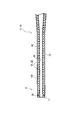
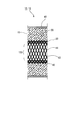
- FIG. 7 is an enlarged view schematically showing the extension region 15 in the second region 14 of the catheter body 110
- FIG. 8 is an enlarged view schematically showing the first region 12. As shown in FIG.
- the medical device (catheter) 100 of this embodiment includes a catheter body 110 having an elongated tubular shape and having an inner hole 120, a hollow hub 500, and a protector 520.
- the hub 500 is provided on the proximal end side of the catheter body 110 so as to communicate with the inner hole 120 of the catheter body 110.
- the protector 520 is provided at the distal end portion of the hub 500 and holds the outer periphery of the second region 14 of the catheter body 110.
- the holding region 16 held by the protector 520 out of the protector 520 and the second region 14 of the catheter main body 110 has both visible light transmittance, The internal state of the hole 120 is visible (see FIG. 7).
- being able to visually recognize the internal state of the inner hole 120 means that when a colored passing material 200 such as blood is passed through the inner hole 120, the passage of the passing material 200 is visually observed under a normal procedure environment. That can be recognized.
- the medical device of this embodiment is a catheter 100, for example. More specifically, the non-active catheter does not have an operation mechanism that bends the distal end portion of the catheter body 110.
- various catheters that are inserted into various body cavities such as the abdominal cavity, thoracic cavity, or ureter can be used.
- the catheter 100 of the present embodiment is particularly preferably used for an intravascular catheter from the viewpoint that blood (back blood) flowing back from the target living tissue to the inner hole 120 of the catheter 100 can be visually confirmed.
- the present invention can be applied to various long medical devices that are used by being inserted into the forceps holes of an endoscope.
- An example of such a medical device is an endoscope puncture needle (local injection needle).
- the puncture needle for endoscope is slidably inserted into an outer tube having a diameter larger than that of the inner tube, and a syringe is inserted into the proximal end of the inner tube.
- a device for discharging a liquid such as a chemical solution from a puncture needle to a target biological tissue is a device for discharging a liquid such as a chemical solution from a puncture needle to a target biological tissue.
- the catheter body 110 is long and hollow, and includes one or a plurality of inner holes 120 therein.
- the catheter body 110 has a length of about several tens of centimeters to several meters. In the present embodiment, the catheter body 110 will be described by roughly dividing it into a first region 12 and a second region 14.
- the first region 12 is a length region of about several millimeters to 1 meter
- the second region 14 is a remaining length region of the catheter body 110.
- the proximal end side of the catheter main body 110 is a gripping part that a user such as a doctor grips with fingers.
- a connecting portion 530 is provided at the proximal end of the hub 500.
- the inside of the connecting portion 530 is open to communicate with the inner hole 120.
- a spiral groove is formed on the outer periphery of the connecting portion 530, and a luer connector of a syringe (not shown) is screwed on.
- medical agents, such as an embolic bead, can be supplied to the catheter main body 110.
- body fluids and obstructions can be sucked from the body cavity through the catheter body 110.
- an instrument such as a guide wire or a stent may be inserted into the opening of the connecting portion 530.
- a plurality of wings 510 are formed around the hub 500. By rotating the wing 510 around the axis of the hub 500, a torque for axially rotating the catheter body 110 can be applied. Thereby, the catheter main body 110 inserted into the body cavity can be oriented in a desired direction.
- the hub 500 is made of a resin material.
- the resin material include polyamide resin (nylon) and polyolefin.
- the hub 500 is visible light transmissive. Thereby, it can be visually confirmed that the insertion depth of the syringe tip is normal. Further, it can be visually confirmed that the medicine is normally discharged from the syringe to the hub 500.
- a connecting recess 56 is formed at the tip of the hub 500, and the proximal end of the catheter body 110 is fitted and fixed to the connecting recess 56.
- the connection recess 56 corresponds to the boundary between the catheter body 110 and the hub 500.
- the protector 520 is a hollow tubular member provided at the tip of the hub 500. A part of the second region 14 (the holding region 16) of the catheter body 110 is inserted through the protector 520. As shown in FIG. 5, a part of the base end side of the coupling recess 56 of the hub 500 is exposed slightly to the proximal side of the protector 520. As a result, the boundary between the catheter body 110 and the grasping portion 50 can be clearly seen through the hub 500 without the protector 520. However, the present invention is not limited to this, and the entire connecting recess 56 of the hub 500 may be covered with the protector 520.
- the protector 520 has a predetermined bending rigidity, and functions as a strain relief that relieves bending stress concentrated on the nearest portion of the catheter body 110 near the hub 500 and prevents kinking of the catheter body 110.
- the protector 520 and the holding region 16 of the catheter body 110 are both visible light transmissive.
- the catheter main body 110 has a visible light transmission property.
- the catheter main body 110 is transparent or translucent and transmits visible light from the outside of the catheter main body 110 to the inner hole 120 to such an extent that the inner state of the inner hole 120 can be visually recognized. It means making it happen.
- the catheter body 110 having visible light transmission means that visible light is transmitted through the multilayer structure as described above.
- the medical device is an endoscope puncture needle (local injection needle)
- the catheter body 110 has a double (multiple) tube structure in which the inner tube is slidably inserted into the outer tube. You may prepare.
- the catheter body 110 has a visible light transmission property in a combined state in which the outer tube and the inner tube are combined, and at least the visible light is transmitted from the outside of the catheter body 110 to the inner hole 120 of the inner tube. Is visible.
- the protector 520 has a visible light transmission property.
- the protector 520 is transparent or translucent, and allows visible light to be transmitted from the outside to the inside of the protector 520 so that the internal state of the hollow tubular protector 520 can be visually recognized. That means.
- the fact that the protector 520 has visible light transmission means that visible light is transmitted through the multilayer structure as described above.
- the catheter body 110 includes the outer tube 10 made of resin, as in the first embodiment.
- the outer tube 10 includes a first region including a distal end portion and a second region including a proximal end portion.
- the first area is more flexible than the second area.
- the medical device of the present embodiment since the medical device of the present embodiment has the same configuration as that of the first embodiment, it maintains good pushability in a complicatedly bent body cavity or an extremely thin body cavity such as a blood vessel end region. However, the branch selectivity is good. Furthermore, according to the catheter 100 of the present embodiment, the medicine circulating inside the catheter main body 110 and the reverse blood reaching the protector 520 from the distal end 11 through the inner hole 120 of the catheter main body 110 are visually confirmed from the outside. Can do. For this reason, it can be visually confirmed that the medicine is normally flowing toward the distal end side of the catheter main body 110 without clogging at the connecting recess 56 which is the boundary between the catheter main body 110 and the hub 500. Further, before the reverse blood reaches the intermediate portion of the hub 500 beyond the protector 520, it can be visually confirmed immediately when the reverse blood reaches the protector 520 at the latest.
- the visible light transmittance of the second region 14 of the catheter body 110 is preferably 50% or more, more preferably 70% or more, and the visible light transmittance of the protector 520 is preferably 30% or more, more preferably 50% or more.
- the visible light transmittance of each member refers to the transmittance of visible light from the outside of the member to the axial center (inner hole 120 in the case of the catheter body 110).
- the catheter 100 according to this embodiment has a visible light transmittance of the second region 14 of the catheter main body 110 and the protector 520 within the above range, so that a colored passing material 200 such as reverse blood passing through the inner hole 120 is removed from the exterior. It is visible from.
- the protector 520 of the present embodiment is made of a resin material and is configured to be transparent or translucent.
- resin materials include styrene-based resins such as olefin-styrene copolymers; polyolefins such as polyethylene, polypropylene and ethylene-vinyl acetate copolymers; polyesters such as polyethylene terephthalate; rubber materials such as silicone rubber; Examples thereof include vinyl chloride, polyurethane and polyamide.
- These resin materials can be used alone or in combination of two or more.
- the visible light transmittance of the protector 520 can be adjusted to the above range by using a mixture of resin materials having different light transmittances at a predetermined ratio.
- the protector 520 may contain a pigment in the range which does not contain a pigment substantially or does not impair transparency or translucency.
- the extended region 15 extending to the distal end side with respect to the protector 520 also has visible light permeability. More specifically, the holding region 16 and the extension region 15 of the catheter body 110 are translucent. And the 1st area
- the passing region 200 such as reverse blood reaches the extending region 15 of the catheter body 110 with the extended region 15 protruding from the parent catheter or endoscope, that is, the reverse blood reaches the protector 520. This can be immediately visually confirmed before reaching (see FIG. 7).
- the catheter body 110 has a laminated structure, and is formed by laminating the inner tube 20 and the outer tube 10 in order from the axial center side.
- a metal protective layer 40 is embedded in the outer tube 10. The metal protective layer 40 is in contact with or close to the outer surface of the inner tube 20.
- the inner tube 20 is a cylindrical member having an inner hole 120 inside. As shown in FIG. 6, the inner hole 120 is enlarged in diameter toward the proximal side in the first region 12 of the catheter body 110.
- Examples of the material of the inner tube 20 include a fluorine-based thermoplastic polymer material.
- Specific examples of the fluorine-based thermoplastic polymer material include polytetrafluoroethylene (PTFE), polyvinylidene fluoride (PVDF), and perfluoroalkoxy fluororesin (PFA). These resin materials can be used alone or in combination of two or more.
- thermoplastic polymers examples include polyurethane (PU) resin, polyimide (PI) resin, polyamideimide (PAI) resin, polyethylene terephthalate (PET) resin, polyethylene (PE) resin, and polyamide (PA) resin.
- PU polyurethane
- PI polyimide
- PAI polyamideimide
- PET polyethylene terephthalate
- PA polyamide
- Nylon elastomer resin ethylene-vinyl acetate resin
- EVA ethylene-vinyl chloride
- PP polypropylene
- the thermoplastic polymer includes a thermoplastic elastomer. These resin materials can be used alone or in combination of two or more.
- thermoplastic elastomer is a concept including a polymer alloy (polymer blend, block copolymerization, graft copolymerization, random copolymerization, etc.), a softening agent such as a plasticizer, and a mixture thereof. is there.
- the elastomer includes urethane elastomer, amide elastomer (nylon elastomer), styrene elastomer, olefin elastomer, and vinyl chloride elastomer.
- the urethane-based elastomer includes a thermoplastic polyurethane elastomer.
- the amide-based elastomer includes a thermoplastic polyamide elastomer or a thermoplastic polyether block amide copolymer.
- the pigment 28 is dispersed in the outer tube 10 in the first region 12 of the catheter body 110.
- region 12 of the catheter main body 110 is visible light impermeability, and its visibility is high. That is, when the first region 12 is visible light transmissive, the instrument table and the like can be seen through the first region 12 in a state where the catheter 100 is placed on the device table and the like, so the visibility of the first region 12 is low.
- the first region 12 is visible-opaque as in the present embodiment, so that good visibility of the first region 12 is ensured.
- the visibility of the first region 12 of the catheter body 110 can be further enhanced by being colored.
- a marker 30 is provided in the vicinity of the distal end 11 of the catheter body 110.
- the marker 30 has a ring shape and is embedded in the outer tube 10 in a state in which the marker 30 is caulked and fixed to the outer periphery of the tip portion of the metal protective layer 40.
- the marker 30 includes a material that does not transmit radiation such as X-rays, and is specifically made of a metal material such as platinum.
- the outer diameter is the same over the extension region 15 and the first region 12 of the catheter body 110. That is, the outer diameter of the catheter body 110 is continuous at the boundary 13 between the visible light transmissive second region 14 and the visible light opaque first region 12. In the first region 12 of the catheter body 110, the outer diameter of the catheter body decreases toward the distal end 11 of the catheter body 110.
- the catheter 100 of this embodiment is an intravascular catheter used by being inserted into a blood vessel such as a celiac artery.
- the dimension of the catheter 100 of this embodiment is demonstrated.
- the outer diameter of the first region 12 of the catheter body 110 can be set to, for example, 550 ⁇ m to 1000 ⁇ m.
- the outer diameter of the second region 14 of the catheter main body 110 can be set to 800 ⁇ m or more and 1100 ⁇ m or less. That is, the maximum outer diameter of the catheter body 110 is about 1 mm in diameter, and preferably 1 mm or less.
- the outer diameter (sheath outer diameter) of the first region 12 of the catheter main body 110 of the present embodiment is reduced in multiple stages (three stages in the present embodiment). At each stage, the catheter body 110 is continuously and smoothly reduced.
- the inner diameter of the inner hole 120 of the catheter body 110 can be 400 ⁇ m or more and 600 ⁇ m or less.
- the inner hole 120 expands toward the proximal side in the first region 12 within the above inner diameter range.
- an outer layer 60 is provided on the outer surface of the catheter body 110 from the first region 12 to the extended region 15.
- the outer layer 60 terminates in the middle of the extension region 15 of the catheter body 110.
- the outer layer 60 includes a hydrophilic material such as polyvinyl alcohol (PVA) or polyvinyl pyrrolidone. These resin materials can be used alone or in combination of two or more.
- the outer layer 60 may be formed by hydrophilizing the surface of the outer tube 10 or may be formed by applying a hydrophilic resin material to the surface of the outer tube 10.
- the outer layer 60 is formed to the proximal end side slightly from the first region 12 that does not transmit visible light in the catheter body 110, and the distal end side from the intermediate portion of the extension region 15. It ends with. In other words, the outer layer 60 terminates at a position slightly beyond the boundary 13 between the first region 12 and the second region 14 (extension region 15) toward the proximal end. Even if a discontinuity occurs in the surface properties of the outer tube 10 at the boundary 13 between the first region 12 where the pigment is mixed in the outer tube 10 and the second region 14 where the pigment is not substantially mixed, the outer layer Since 60 covers the boundary portion 13, discontinuity of sliding resistance of the catheter body 110 does not occur at the boundary portion 13.
- the metal protective layer 40 is a protective layer for improving the kink resistance of the catheter body 110 and the pressure resistance of the inner tube 20.
- the metal protective layer 40 is a coil in which one or a plurality of wires 41 are spirally wound, or a mesh in which a plurality of wires 41 are braided.
- the material of the wire 41 constituting the metal protective layer 40 is higher in rigidity than the inner tube 20 and the outer tube 10, and for example, a metal material can be used. Specifically, tungsten, stainless steel (SUS), nickel titanium alloy, steel, titanium, or copper alloy can be used. In addition, a resin material can be used for the wire 41. These resin materials can be used alone or in combination of two or more.
- the metal protective layer 40 of this embodiment is a mesh formed by braiding wires 41.
- the metal protective layer 40 is provided in at least the second region 14 of the catheter body 110.
- the opening area ratio of the metal protective layer 40 in the second region 14 of the catheter body 110 exceeds 50%.
- the metal protective layer 40 of the present embodiment is configured such that multiple (for example, eight) wires 41 are wound in a right spiral around the outer periphery of the inner tube 20, and the multiple (for example, eight) wires 41 are wound on the outer periphery of the inner tube 20.
- the wire 41 can be knitted together and wound around the left spiral.
- the entire catheter body 110 can be visible-light transmissive.
- the mesh openings 42 of the metal protective layer 40 are gap portions of the wires 41 that intersect each other.
- the opening area ratio of the metal protective layer 40 is a ratio of a gap portion (mesh opening 42) where the wire 41 does not exist in the peripheral area of the cylindrical metal protective layer 40.
- the opening area ratio may be calculated theoretically based on the wire diameter and pitch of the wire 41, or may be calculated by calculating the area based on the image of the catheter main body 110 (metal protective layer 40).
- the pitch of the wires 41 is an axial distance between the wires 41 wound in the same direction and adjacent to each other.
- the metal protective layer 40 of the present embodiment is provided from the first region 12 to the second region 14 of the catheter main body 110.
- the opening area ratio (proximal opening ratio) of the metal protective layer 40 (see FIG. 7) in the second region 14 of the catheter body 110 is the opening of the metal protective layer 40 (see FIG. 8) in the first region 12 of the catheter body 110. It is larger than the area ratio (tip opening ratio).
- the metal protective layer 40 does not impair the visibility inside the inner hole 120 in the extension region 15 and the holding region 16 of the second region 14 of the catheter body 110.
- the proximal end opening ratio is preferably 70% or more and 90% or less. Thereby, the visible light permeability in the second region 14 of the catheter body 110 can be increased, and the kink resistance of the second region 14 of the catheter body 110 can be ensured.
- the metal protective layer 40 is continuously formed from the first region 12 to the second region 14 by the same number of wires 41.
- the pitch interval of the wires 41 in the first region 12 of the catheter body 110 is smaller than the pitch interval of the wires 41 in the second region 14.
- the pitch interval of the wires 41 gradually increases toward the proximal end side.
- the spring property of the metal protective layer 40 can be increased by decreasing the pitch interval of the wires 41 in the first region 12 of the catheter body 110 to reduce the tip opening ratio. For this reason, the first region 12 of the catheter body 110 can be flexibly bent.
- the distal end opening ratio is smaller than the proximal end opening ratio, and is preferably 50% or more and 80% or less.
- a plurality of components are formed as one member, a component is formed of a plurality of members, one component is a part of another component, and one component is The part and other components are allowed to overlap.
- Example 1 A catheter was created with the same configuration as the catheter 100 illustrated in the first embodiment. Specifically, the diameter 558 of the inner hole 120 at the distal end of the catheter body 110 was 500 ⁇ m, and the outer diameter 550 was 670 ⁇ m (see FIG. 1). That is, the thickness of the outer tube 10 in the first region 12 was set to 85 ⁇ m. Pelecene 80AE (manufactured by Dow Chemical Japan Co., Ltd.) was used as the first resin member constituting the first region 12. The catheter produced as described above was taken as Example 1.
- Comparative Example 1 As a first resin member constituting the first region 12, a Pebax 2533 (provided by Tokyo Materials Co., Ltd.) was used, and a catheter configured in the same manner as in Example 1 was prepared except that 40% by mass of barium sulfate was contained therein. This was designated as Comparative Example 1.
- a tip bending load test was performed as follows. First, a guide pipe having both ends opened and having a hole with an inner diameter of 0.8 mm extending in the linear direction and a length of 3 cm was prepared. An electronic balance was placed so that the measurement surface was horizontal. The guide pipe is fixed so that the extending direction of the hole is perpendicular to the measurement surface and the distance from the lower end of the guide pipe (lower end opening of the hole) to the measurement surface of the electronic balance is 5 mm. did.
- Example 1 In a temperature environment of normal temperature (23 ° C.), the tip of Example 1 was entered from the upper end of the hole in the guide pipe and exposed from the lower end of the hole. The tip of Example 1 was pressed against the measurement surface of the electronic balance until the exposed length from the lower end was 7 mm. Thereby, the load displayed on the electronic balance was measured as “room temperature environmental load”. The measurement was performed 5 times. In Comparative Example 1, the room temperature environmental load was measured in the same manner as in Example 1.
- Example 1 Next, from the tip of Example 1 to about 80 cm, it was immersed for 10 minutes in a thermostat whose temperature was adjusted to 38 ° C. Except for using the catheter immediately after removal from the thermostat, the load was measured in the same manner as the room temperature environmental load measurement method, and this was designated as “body temperature environmental load”. The body temperature environmental load was similarly measured for Comparative Example 1.
- excluded the highest value and the lowest value from the normal temperature environmental load (N 5) measured as mentioned above was calculated
- the average value of the normal temperature environmental load of Example 1 is 1.048 (gf)
- the average value of the body temperature environmental load is 0.730 (gf)
- average values of normal temperature environmental load and body temperature environmental load of Comparative Example 1 were also obtained.
- the average value of the normal temperature environmental load is 1.212 (gf)
- the average value of the body temperature environmental load is 1.105 (gf)
- Example 1 had a greater degree of softening in the tip region after heating to 38 ° C. than Comparative Example 1. Since Example 1 and Comparative Example 1 are configured similarly except that the resin member constituting the first region 12 of the outer tube 10 is different, the difference between the difference A and the difference B is exclusively used. It was understood that it originated in the property of the obtained resin member.
- thermoplastic urethane elastomer is used as the first resin member constituting the first region 12, and the amide elastomer is used as the second resin member constituting the second region 14. It was estimated that the difference X in the first region 12 is larger than the difference Y in the second region 14. That is, it was inferred that exposure to a temperature environment of 38 ° C. for a predetermined time increased the degree of softening of the first region 12 compared to the second region 14 and improved the branching selectivity of the catheter.
Landscapes
- Health & Medical Sciences (AREA)
- Life Sciences & Earth Sciences (AREA)
- Biophysics (AREA)
- Pulmonology (AREA)
- Engineering & Computer Science (AREA)
- Anesthesiology (AREA)
- Biomedical Technology (AREA)
- Heart & Thoracic Surgery (AREA)
- Hematology (AREA)
- Animal Behavior & Ethology (AREA)
- General Health & Medical Sciences (AREA)
- Public Health (AREA)
- Veterinary Medicine (AREA)
- Media Introduction/Drainage Providing Device (AREA)
Abstract
本発明は屈曲した体腔、あるいは血管末端領域などの極細い体腔において、良好なプッシャビリティを維持しつつ、分岐選択性の良好な樹脂管を備える医療機器を提供する。体腔内に挿入される医療機器本体を有する医療機器であって、上記医療機器本体は、長尺な樹脂管を有し、上記樹脂管は、遠位端部を含む第一領域と、近位端部を含む第二領域とを具備し、上記第一領域が上記第二領域よりも柔軟な医療機器を提供する。
Description
本発明は、医療機器に関する。
本願は、2014年6月3日に、日本に出願された特願2014‐114889号および特願2014-114891号に基づき優先権を主張し、その内容をここに援用する。
本願は、2014年6月3日に、日本に出願された特願2014‐114889号および特願2014-114891号に基づき優先権を主張し、その内容をここに援用する。
近年、血管等の体腔に挿入可能であるカテーテルの開発が行なわれている。一般に、カテーテルは、ガイドワイヤを用いたオーバーザワイヤという手法で体腔に挿入される。所望の分岐路に先行してガイドワイヤを屈曲状態で留置し、その基端側からカテーテルを被せてガイドワイヤに沿って押し込んでいく。これにより、分岐路を選択することができる。体腔の分岐において所望の分岐路を選択し、さらに挿入方向に進行するために、カテーテルは適度に柔軟に形成されることが一般的である。そのため、カテーテルは長尺であって可撓性を有する樹脂管を備えることが一般的である。特に、血管末端領域等のように、分岐が多く複雑に曲がる細い体腔にも適用でき良好に分岐選択可能とするための樹脂管を備えるカテーテルが提案されている。
たとえば、特許文献1に記載のカテーテル(以下、従来技術1ともいう)は、基端部と、先端部との硬度、つまり柔軟性が異なる樹脂外層を備える。具体的には、ショアD硬度が異なる4種のポリエーテルエステルアミドエラストマー用いて、樹脂外層である樹脂管が構成されている。上記4種のポリエーテルエステルアミドエラストマーの硬度は、該ポリエーテルエステルアミドエラストマーのハードセグメントの重量比に比例していることが特許文献1に説明されている。
また、上記カテーテルや内視鏡用穿刺針などの長尺の医療機器は、可撓性を有していて長尺のシースと手元側のハブとを備えている点で共通している。シースは先端から基端まで延びる1個または複数個の内孔(ルーメン)を備えており、この内孔の内部に薬液、造影剤、ガイドワイヤ、穿刺針その他の医療機器など各種の物品が供給される。シースは、医療機器の種類により、1重の管体や2重の管体が用いられる。
ハブは、ユーザのハンドリング性が良好になるよう、シースよりも太径で硬質の材料で作成されることが一般的である。ハブは中空でシースの内孔と連通しており、ハブの基端にはシリンジを取り付けるコネクタが設けられることが一般的である。
この種の医療機器に関し、特許文献2には、2重の管体で構成される長尺のシース(カテーテル本体)と、このシースの基端部に設けられたハブとを備える医療機器(カテーテル)が記載されている。シースの基端部はハブの内部に挿入されて固定されており、この固定部の近傍を耐キンクプロテクタ(プロテクタ)で保持している。プロテクタは、シースの基端部が折れ曲がって内孔が閉塞すること(キンク)を防止する筒状の保護部材であり、ハブの先端部に設けられている。プロテクタは、コネクタカバーやストレインリリーフなどとも呼称され、十分な曲げ剛性および硬度を有している。
シースは、ポリウレタン系樹脂やポリアミド系樹脂などの樹脂材料を主成分として作成される。器具台や手術台に載置された状態での視認性を向上させるため、シースは不透明で様々な色に着色されることが一般的である。一方、特許文献3および特許文献4には、シースを透明にして、内部を通過する薬液を外部から目視確認できるようにした医療機器が記載されている。
ところで、カテーテルは、非分岐領域または比較的に内径の太く屈曲角度の緩やかな分岐路では、ガイドワイヤに沿って前進方向に押し込まれるようにして体腔を前進する。そのため、カテーテルは、先端部も含めて、良好なプッシャビリティが示される程度に、ガイドワイヤに対する摺動性に加えて、適度な剛性を備えることが好ましい。すなわち、カテーテルの樹脂管は、良好なプッシャビリティを備えるべく、適度な剛性が求められる。
一方、内径が細く屈曲角度の急な分岐路等、分岐選択が容易でない領域にさしかかった場合、良好な分岐選択性を得るために、上記樹脂管の先端部が柔軟であることが好ましい。これにより、分岐路に留置されたガイドワイヤの屈曲状態を体腔で維持したままカテーテルを所望の分岐路に挿入することができる。しかしながら先端が硬いとガイドワイヤに沿ってカテーテルを押し込んでいくときに、ガイドワイヤの先端部を所望の分岐路に屈曲状態で留置しておくことができず、分岐選択性が不良となる場合がある。
このように、先端部も含めて良好なプッシャビリティを発揮可能であるとともに、分岐路においてカテーテルの先端部が良好な分岐選択性を示す程度に柔軟性を発揮するといった、複合的な要請に応え得るカテーテルは未だ提案されていなかった。
また、この種の医療機器を体腔に挿入する場合には、被験者にガイディングカテーテル(親カテーテル)や内視鏡を留置し、これらの近位端部にあるコネクタや手元操作部から当該医療機器を挿入することが一般的である。医療機器を体腔に深く挿入した場合、医療機器のハブは、ガイディングカテーテルのコネクタや内視鏡の手元操作部(以下、体腔導入口という場合がある)の近傍に達することがある。
ここで、先に説明したように、ハブは透明な樹脂材料で作成され、薬液が充填されたシリンジの先端がハブに正常に装着されていることが目視確認できるようになっているものがある。これに対し、プロテクタは不透明な樹脂材料で形成され、これにより器具台や手術台に載置された状態での医療機器の視認性を確保している。
このような医療機器においては、シリンジからシースに薬液が正常に供給されて先端側に向かって流動していることを目視確認すること、シースの先端開口から被験者の血液が流入してシースの基端側に向かって流動してきていること(逆血)を目視的に迅速に発見することが求められている。しかしながら、特許文献2や特許文献3のようにシースを透明にしても、ハブやプロテクタが体腔導入口に接近するまでシースを体腔に深く挿入してしまうと、シースの壁面を通じて内孔の内部を視認することができなくなる。このため、シースを体腔に深く挿入して先端を目的の生体組織の近傍まで到達させ、次いで薬液を吐出したり各種の手技操作をしたりする際に、薬液の流動や逆血の発生を目視確認できないという問題がある。
本発明は上記課題に鑑みてなされたものである。すなわち、本発明は、複雑に屈曲した体腔、あるいは血管末端領域などの極細い体腔において、良好なプッシャビリティを維持しつつ、分岐選択性の良好な樹脂管を備える医療機器を提供することを課題とする。
さらに、上記優れたプッシャビリティおよび分岐選択性を具備するとともに、シースを体腔に十分に深く挿入した状態でもシースの内孔の内部状態を目視確認することが可能な医療機器を提供するものである。
さらに、上記優れたプッシャビリティおよび分岐選択性を具備するとともに、シースを体腔に十分に深く挿入した状態でもシースの内孔の内部状態を目視確認することが可能な医療機器を提供するものである。
上記課題を解決するため、本発明は以下(1)から(19)の医療機器を提供する。
(1) 体腔内に挿入される医療機器本体を有する医療機器であって、
上記医療機器本体は、長尺な樹脂管を有し、
上記樹脂管は、挿入先端側端部を含む第一領域と、基端側端部を含む第二領域とを具備し、
上記第一領域が上記第二領域よりも柔軟な医療機器。
(1) 体腔内に挿入される医療機器本体を有する医療機器であって、
上記医療機器本体は、長尺な樹脂管を有し、
上記樹脂管は、挿入先端側端部を含む第一領域と、基端側端部を含む第二領域とを具備し、
上記第一領域が上記第二領域よりも柔軟な医療機器。
(2) 前記第一領域は、第一樹脂部材から構成され、
前記第二領域は、上記第一樹脂部材とは異なる樹脂部材で構成され、
常温において測定された上記第一樹脂部材の樹脂硬度と、38℃の温度環境で所定時間放置された後に測定された上記第一樹脂部材の樹脂硬度との差異Xが、常温において測定された上記第二樹脂部材の樹脂硬度と、38℃の温度環境で所定時間放置された後に測定された上記第二樹脂部材の樹脂硬度との差異Yよりも大きいことを特徴とする(1)記載の医療機器。
前記第二領域は、上記第一樹脂部材とは異なる樹脂部材で構成され、
常温において測定された上記第一樹脂部材の樹脂硬度と、38℃の温度環境で所定時間放置された後に測定された上記第一樹脂部材の樹脂硬度との差異Xが、常温において測定された上記第二樹脂部材の樹脂硬度と、38℃の温度環境で所定時間放置された後に測定された上記第二樹脂部材の樹脂硬度との差異Yよりも大きいことを特徴とする(1)記載の医療機器。
(3) 前記第一樹脂部材は第一樹脂を50%以上含み、前記第二樹脂部材は前記第一樹脂とは異なる樹脂である第二樹脂を50%以上含む(2)に記載の医療機器。
(4) 前記第一樹脂が熱可塑性ポリウレタン系樹脂であり、前記第二樹脂がポリアミド系樹脂である(2)または(3)のいずれかに記載の医療機器。
(5) 前記第一樹脂部材および前記第二樹脂部材が、
(I)常温において測定される前記第一樹脂部材の前記樹脂硬度が前記第二樹脂部材の前記樹脂硬度以上であり、
(II)38℃の温度環境に所定時間放置された後に測定される前記第一樹脂部材の前記樹脂硬度が前記第二樹脂部材の前記樹脂硬度未満である(2)から(4)のいずれかに記載の医療機器。
(I)常温において測定される前記第一樹脂部材の前記樹脂硬度が前記第二樹脂部材の前記樹脂硬度以上であり、
(II)38℃の温度環境に所定時間放置された後に測定される前記第一樹脂部材の前記樹脂硬度が前記第二樹脂部材の前記樹脂硬度未満である(2)から(4)のいずれかに記載の医療機器。
(6) 前記樹脂管の内周に積層された内管を有し、
前記内管の先端は、軸心方向において前記第一領域の先端と同位置に位置する(2)から(5)のいずれかに記載の医療機器。
前記内管の先端は、軸心方向において前記第一領域の先端と同位置に位置する(2)から(5)のいずれかに記載の医療機器。
(7) 前記第一領域の先端は、前記樹脂管の先端を構成する(2)から(6)のいずれかに記載の医療機器。
(8) 遠位端部に設けられX線不透過金属材料を含むマーカーが前記第一樹脂部材に被覆されている(2)から(7)のいずれかに記載の医療機器。
(9) 前記樹脂管の内周側または内部に設けられた金属保護層を有し、
前記金属保護層の先端が、軸心方向において前記第一領域の先端よりも基端部側端部よりに位置する(2)から(8)のいずれかに記載の医療機器。
前記金属保護層の先端が、軸心方向において前記第一領域の先端よりも基端部側端部よりに位置する(2)から(8)のいずれかに記載の医療機器。
(10) 軸心方向における前記第一領域の寸法は、5mm以上15mm以下である(2)から(9)のいずれかに記載の医療機器。
(11) ワイヤを編組してなる金属保護層が前記樹脂管の少なくとも前記第二領域の内部に設けられており、前記樹脂管の基端側端部における上記金属保護層の開口面積比率が50%を超えることを特徴とする(1)に記載の医療機器。
(12) 前記金属保護層が前記樹脂管の第一領域および第二領域に設けられており、
前記第二領域の基端側端部における金属保護層の開口面積比率が、前記第一領域の挿入先端側端部における開口面積比率よりも大きいことを特徴とする(11)に記載の医療機器。
前記第二領域の基端側端部における金属保護層の開口面積比率が、前記第一領域の挿入先端側端部における開口面積比率よりも大きいことを特徴とする(11)に記載の医療機器。
(13) 前記第二領域から前記第一領域にかけてワイヤのピッチ間隔が徐々に狭くなることを特徴とする(11)または(12)に記載の医療機器。
(14) 前記医療機器が、前記樹脂管の内孔と連通するように前記樹脂管の基端側端部に設けられた中空のハブと、上記ハブの先端部に設けられて前記樹脂管の基端側端部の外周を保持するプロテクタとをさらに具備し、
上記プロテクタと、前記樹脂管の基端側端部のうち前記プロテクタで保持されている保持領域とが、いずれも可視光透過性を有し前記内孔の内部状態を視認可能であることを特徴とする(1)記載の医療機器。
上記プロテクタと、前記樹脂管の基端側端部のうち前記プロテクタで保持されている保持領域とが、いずれも可視光透過性を有し前記内孔の内部状態を視認可能であることを特徴とする(1)記載の医療機器。
(15) 前記樹脂管の基端側端部のうち前記プロテクタよりも先端側に延出する延出領域が可視光透過性を有し、前記樹脂管のうち前記延出領域よりも先端側に位置する先端部が可視光不透過性を有する(14)に記載の医療機器。
(16) 前記樹脂管の前記保持領域および前記延出領域が半透明である(15)に記載の医療機器。
(17) 前記樹脂管の前記延出領域と前記先端部とに亘って樹脂管外径が同径であり、前記樹脂管の前記先端部は前記樹脂管の遠位端に向かって前記樹脂管外径が縮小している(15)または(16)に記載の医療機器。
(18) 前記挿入先端側端部から前記延出領域に亘って前記樹脂管の外表面に親水性コート層が設けられており、上記親水性コート層は前記延出領域の途中で終端していることを特徴とする(15)から(17)のいずれかに記載の医療機器。
(19) カテーテルである(1)から(18)のいずれかに記載の医療機器。
本発明は、先端部が所定の条件において基端部よりも柔軟化する樹脂管を備える。これにより、本発明の医療機器は、複雑に屈曲した体腔、あるいは血管末端領域などの極細い体腔において、良好なプッシャビリティを維持しつつ、分岐選択性が良好である。
本発明の医療機器によれば、上記優れた効果を具備するうえに、シース(カテーテル本体)を体腔に十分に深く挿入した状態でも、プロテクタを通じてカテーテル本体の内孔の内部状態を目視確認することが可能である。これにより、カテーテル本体の先端が目的の生体組織の近傍まで到達した状態でも、薬液の注入不良や逆血の発生を迅速に知得することができる。
以下、本発明の第一実施形態について、図面を用いて説明する。すべての図面において、同様の構成要素には同一の符号を付し、重複する説明は適宜に省略する。
本発明の医療機器の各種の構成要素は、個々に独立した存在である必要はなく、複数の構成要素が一個の部材として形成されていること、一つの構成要素が複数の部材で形成されていること、ある構成要素が他の構成要素の一部であること、ある構成要素の一部と他の構成要素の一部とが重複していること等を許容する。
本発明の医療機器の各種の構成要素は、個々に独立した存在である必要はなく、複数の構成要素が一個の部材として形成されていること、一つの構成要素が複数の部材で形成されていること、ある構成要素が他の構成要素の一部であること、ある構成要素の一部と他の構成要素の一部とが重複していること等を許容する。
本発明における用語または本発明を説明する際に用いられる用語は、特段の断りがない限り、以下のとおり定義される。
本発明を説明する際、適宜、「遠位端」、「遠位端部」および「近位端部」という用語を使用する場合がある。ここで、「遠位端」とは医療機器本体の挿入先端を意味し、「遠位端部」とは遠位端を含む所定の長さ領域をいう。また「近位端部」とは、当該医療機器本体の基端側の端部(近位端)を含む所定の長さ領域をいう。本発明において軸心とは、医療機器本体の長尺方向における中心軸を意味する。
本明細書において医療機器の「縦断面」とは、医療機器(実施形態ではカテーテル)を、その軸心を通って長手方向に平行に切断した断面をいう。
「樹脂硬度」とは、樹脂部材自体の物性値を意味する。たとえば、ショア硬度などの公知の試験方法に準拠して第一樹脂部材または第二樹脂部材の樹脂硬度を測定することができる。なお、上記樹脂硬度に関し、第一樹脂部材または第二樹脂部材に、造影剤、任意のフィラーなどの樹脂以外の添加剤が含有されている場合には、それらが含有された第一樹脂部材または第二樹脂部材の樹脂硬度を意味する。
本発明を説明する際、適宜、「遠位端」、「遠位端部」および「近位端部」という用語を使用する場合がある。ここで、「遠位端」とは医療機器本体の挿入先端を意味し、「遠位端部」とは遠位端を含む所定の長さ領域をいう。また「近位端部」とは、当該医療機器本体の基端側の端部(近位端)を含む所定の長さ領域をいう。本発明において軸心とは、医療機器本体の長尺方向における中心軸を意味する。
本明細書において医療機器の「縦断面」とは、医療機器(実施形態ではカテーテル)を、その軸心を通って長手方向に平行に切断した断面をいう。
「樹脂硬度」とは、樹脂部材自体の物性値を意味する。たとえば、ショア硬度などの公知の試験方法に準拠して第一樹脂部材または第二樹脂部材の樹脂硬度を測定することができる。なお、上記樹脂硬度に関し、第一樹脂部材または第二樹脂部材に、造影剤、任意のフィラーなどの樹脂以外の添加剤が含有されている場合には、それらが含有された第一樹脂部材または第二樹脂部材の樹脂硬度を意味する。
<第一実施形態>
以下に、本発明の医療機器に関し、本発明の第一実施形態であるカテーテル100の構成について図1から図3を用いて説明する。
図1は、本発明の第一実施態様における医療機器であるカテーテル100の全体図である。図2は、カテーテル100の先端部の縦断面図である。図3は、第一実施態様であるカテーテル本体110の先端部の説明図である。図3は図2で示す先端部を拡大した図である。図3は、外管10および外層60を断面視するとともに、内管20、マーカー30、金属保護層40を側面視している。
以下に、本発明の医療機器に関し、本発明の第一実施形態であるカテーテル100の構成について図1から図3を用いて説明する。
図1は、本発明の第一実施態様における医療機器であるカテーテル100の全体図である。図2は、カテーテル100の先端部の縦断面図である。図3は、第一実施態様であるカテーテル本体110の先端部の説明図である。図3は図2で示す先端部を拡大した図である。図3は、外管10および外層60を断面視するとともに、内管20、マーカー30、金属保護層40を側面視している。
本実施形態にかかる医療機器(カテーテル100)は、長尺で可撓性を有し、体腔内に挿入される医療機器本体(カテーテル本体110)を有している。医療機器本体(カテーテル本体110)は、長尺な樹脂管(外管10)を有している。樹脂管(外管10)は、第一樹脂部材から構成される第一領域12と、第一樹脂部材とは異なる樹脂部材である第二樹脂部材から構成され第一領域12よりも近位側に位置する第二領域14とを有している。
医療機器(カテーテル100)において、常温において測定された第一樹脂部材の樹脂硬度と、38℃の温度環境で所定時間放置された後に測定された第一樹脂部材の樹脂硬度との差異Xは、常温において測定された第二樹脂部材の樹脂硬度と、38℃の温度環境で所定時間放置された後に測定された第二樹脂部材の樹脂硬度との差異Yよりも大きくなるよう構成されている。
医療機器(カテーテル100)において、常温において測定された第一樹脂部材の樹脂硬度と、38℃の温度環境で所定時間放置された後に測定された第一樹脂部材の樹脂硬度との差異Xは、常温において測定された第二樹脂部材の樹脂硬度と、38℃の温度環境で所定時間放置された後に測定された第二樹脂部材の樹脂硬度との差異Yよりも大きくなるよう構成されている。
かかる構成により、第一領域12も含め、体腔に挿入されたときには、外管10は良好なプッシャビリティを発揮する程度の剛性を有し得る。そして、体腔において体温(すなわち、38℃程度の温度)にしばらく晒されるうちに、外管10における第一領域12が顕著に軟化しカテーテル本体110の先端部が柔軟になり、これによってカテーテル100の分岐選択性が向上する。
分岐選択が困難で選択操作に時間がかかる箇所、あるいは所定時間かけて到達するような体腔末端領域(例えば血管末端領域)箇所において、分岐選択性が向上することは、カテーテル100の操作上、大変有利である。
分岐選択が困難で選択操作に時間がかかる箇所、あるいは所定時間かけて到達するような体腔末端領域(例えば血管末端領域)箇所において、分岐選択性が向上することは、カテーテル100の操作上、大変有利である。
第一樹脂部材と第二樹脂部材とは、異なる樹脂部材であるため、上述する異なる温度特性を示し得る。ここで異なるとは、第一樹脂部材と第二樹脂部材とが、それぞれ一の異種の樹脂からなる態様、一方が一の樹脂からなり他方が複数の異種の樹脂を含む組成物である態様、それぞれが複数の異種の樹脂を含む組成物である態様を含む。たとえば第一樹脂部材と第二樹脂部材とは、互いに含有される二以上の樹脂成分が同一の樹脂組成物であって成分比率が異なっていてもよい。
たとえば、所定の箇所からカテーテル100を血管内に侵入させ、所望の生体組織まで侵入させるとき、分岐選択が困難な箇所にさしかかった場合には、分岐選択の操作に所定の時間を要することとなる。かかる場合に、当該操作時間の経過中に第一領域12を構成する第一樹脂の樹脂硬度が常温環境時の樹脂硬度と比して顕著に低下する。つまり、カテーテル本体110が柔軟化し、カテーテル100の分岐選択性が向上する。
以下に、本実施形態にかかる医療機器を詳細に説明する。
本実施形態にかかる医療機器(以下、カテーテル100ともいう)は、医療機器本体(以下、カテーテル本体110ともいう)を備える。カテーテル本体110は、長尺で可撓性を有し体腔内に挿入される。カテーテル本体110は、長尺な樹脂管である外管10および、外管10の内周側に積層された内管20を有している。内管20の外周には、ワイヤ41が所定間隔で巻回されてなる金属保護層40が設けられている。
本実施形態にかかる医療機器(以下、カテーテル100ともいう)は、医療機器本体(以下、カテーテル本体110ともいう)を備える。カテーテル本体110は、長尺で可撓性を有し体腔内に挿入される。カテーテル本体110は、長尺な樹脂管である外管10および、外管10の内周側に積層された内管20を有している。内管20の外周には、ワイヤ41が所定間隔で巻回されてなる金属保護層40が設けられている。
カテーテル100は、血管内に挿通させて用いられる血管内カテーテルであることが好適な一例である。
本実施形態にかかるカテーテル100は、たとえば、非能動カテーテルである。すなわち、カテーテル100は、ガイドワイヤを用いたオーバーザワイヤという手法で体腔に挿入されるカテーテル本体110を備える非能動カテーテルとして用いることができ、先端部を屈曲させる操作機構を有していない。
上述のとおりカテーテル100は、体腔において所定の時間が経過したとき第一領域12が第二領域14に比して柔軟化するため、ガイドワイヤに対する追随性が良好である。
上述のとおりカテーテル100は、体腔において所定の時間が経過したとき第一領域12が第二領域14に比して柔軟化するため、ガイドワイヤに対する追随性が良好である。
外管10は、長尺で中空の樹脂管である。外管10は、上述のとおり第一領域12および第二領域14を備えている。
本実施形態において、第一領域12は、外管10の先端部(遠位端部)を構成している。また第二領域14は、外管10の基端部(近位端部)を構成している。外管10の先端部とは、カテーテル本体110の遠位側における外管10の先端を含む所定領域または当該先端を含まない先端寄りの所定領域である。また本実施形態において、外管10の基端部とは、上記先端部よりもカテーテル本体110の近位側に位置する領域であって、カテーテル本体110の近位側における外管10の基端を含む所定領域または当該基端を含まない基端寄りの所定領域である。
本実施形態では、具体的には、図2および図3に示すとおり、外管10の先端部である第一領域12はカテーテル本体110の遠位側における外管10の先端を含む所定領域である。
本実施形態において、第一領域12は、外管10の先端部(遠位端部)を構成している。また第二領域14は、外管10の基端部(近位端部)を構成している。外管10の先端部とは、カテーテル本体110の遠位側における外管10の先端を含む所定領域または当該先端を含まない先端寄りの所定領域である。また本実施形態において、外管10の基端部とは、上記先端部よりもカテーテル本体110の近位側に位置する領域であって、カテーテル本体110の近位側における外管10の基端を含む所定領域または当該基端を含まない基端寄りの所定領域である。
本実施形態では、具体的には、図2および図3に示すとおり、外管10の先端部である第一領域12はカテーテル本体110の遠位側における外管10の先端を含む所定領域である。
すなわち、本実施形態にかかる医療機器(カテーテル100)は、第一領域12の先端が、樹脂管(外管10)の先端を構成している。
したがって、分岐選択の操作において有意に時間を要するような場合に、第一領域12の柔軟化が、カテーテル本体110の先端部の柔軟化に良好に貢献する。
したがって、分岐選択の操作において有意に時間を要するような場合に、第一領域12の柔軟化が、カテーテル本体110の先端部の柔軟化に良好に貢献する。
第一領域12は、第一樹脂部材より構成されている。
第一樹脂部材は、1以上の樹脂を含む。すなわち、第一樹脂部材は、第一樹脂のみから構成されてもよいし、第一樹脂と、これ以外の1以上の他の樹脂とが配合されてなる樹脂組成物であってもよい。
第一樹脂部材は、1以上の樹脂を含む。すなわち、第一樹脂部材は、第一樹脂のみから構成されてもよいし、第一樹脂と、これ以外の1以上の他の樹脂とが配合されてなる樹脂組成物であってもよい。
第二領域14は、第二樹脂部材より構成されている。
第二樹脂部材は、1以上の樹脂を含む。すなわち、第二樹脂部材は、第二樹脂のみから構成されてもよいし、第二樹脂と、これ以外の1以上の他の樹脂とが配合されてなる樹脂組成物であってもよい。
第一樹脂と第二樹脂とは、異種の樹脂である。
第二樹脂部材は、1以上の樹脂を含む。すなわち、第二樹脂部材は、第二樹脂のみから構成されてもよいし、第二樹脂と、これ以外の1以上の他の樹脂とが配合されてなる樹脂組成物であってもよい。
第一樹脂と第二樹脂とは、異種の樹脂である。
なお、第一領域12を構成する第一樹脂部材および第二領域14を構成する第二樹脂部材には、適宜、樹脂以外の成分として任意の配合剤を含有させてもよい。たとえば、カテーテル本体110の位置を確認するために、第一領域12および/または第二領域14に適当な量の造影剤を含有させてもよい。また第一領域12および/または第二領域14所望の色に着色するための顔料を含有させてもよく、上記配合剤はこれらの例示に限定されない。
上記第一樹脂および上記第二樹脂、あるいはこれらに配合されるその他の樹脂は、例えば、熱可塑性ポリマーであることが挙げられる。この熱可塑性ポリマーとしては、ポリウレタン(PU)系樹脂、ポリイミド(PI)系樹脂、ポリアミドイミド(PAI)系樹脂、ポリエチレンテレフタレート(PET)系樹脂、ポリエチレン(PE)系樹脂、ポリアミド(PA)系樹脂、ナイロンエラストマー系樹脂、エチレン-酢酸ビニル系樹脂(EVA)、ポリ塩化ビニル(PVC)系樹脂またはポリプロピレン(PP)系樹脂、またはこれらの組み合わせを挙げることができる。
上記熱可塑性ポリマーとしては、熱可塑性エラストマーを例示できる。
本明細書において熱可塑性エラストマーとは、ポリマーアロイ(ポリマーブレンド、ブロック共重合、グラフト共重合、ランダム共重合等)や、可塑剤等で軟質化したもの、さらにはこれらの混合物をも含む概念である。上記エラストマーとしては、ウレタン系エラストマー、アミド系エラストマー(ナイロン系エラストマー)、スチレン系エラストマー、オレフィン系エラストマー、および塩ビ系エラストマーを例示できる。上記ウレタン系エラストマーは、例えば熱可塑性ポリウレタンエラストマー等である。上記アミド系エラストマーとしては、熱可塑性ポリアミドエラストマー、または熱可塑性ポリエーテルブロックアミド共重合体等が例示できる。
上記熱可塑性ポリマーとしては、熱可塑性エラストマーを例示できる。
本明細書において熱可塑性エラストマーとは、ポリマーアロイ(ポリマーブレンド、ブロック共重合、グラフト共重合、ランダム共重合等)や、可塑剤等で軟質化したもの、さらにはこれらの混合物をも含む概念である。上記エラストマーとしては、ウレタン系エラストマー、アミド系エラストマー(ナイロン系エラストマー)、スチレン系エラストマー、オレフィン系エラストマー、および塩ビ系エラストマーを例示できる。上記ウレタン系エラストマーは、例えば熱可塑性ポリウレタンエラストマー等である。上記アミド系エラストマーとしては、熱可塑性ポリアミドエラストマー、または熱可塑性ポリエーテルブロックアミド共重合体等が例示できる。
第一樹脂部材および第二樹脂部材の樹脂硬度は特に限定されないが、常温の温度環境において外管10に良好なプッシャビリティを付与可能な程度の樹脂硬度であることが好ましい。常温とは、厳密に特定された温度ではないが、たとえば23℃±2℃程度である。
カテーテル100において、常温環境で測定された第一樹脂部材の樹脂硬度と、38℃の温度環境で所定時間放置された後に測定された第一樹脂部材の樹脂硬度との差異を差異Xとする。また、常温環境で測定された第二樹脂部材の樹脂硬度と、38℃の温度環境で所定時間放置された後に測定された第二樹脂部材の樹脂硬度との差異を差異Yとする。差異Xは差異Yよりも大きい。
たとえば、差異Xは、適当なサイズにカットされた第一樹脂部材からなる第一試験片を用い、ISO868に準じて常温の温度環境にて測定したショア硬度(硬度A-1)を測定する。次いで、上記第一試験片を38℃に保温した恒温槽に所定時間浸漬し、ISO868に準じて測定したショア硬度(硬度A-2)を測定する。(硬度A-1)から(硬度A-2)を減じた値が差異Xである。
差異Yは、第一試験片と同様のサイズにカットされた第二樹脂部材からなる第二試験片を用い、(硬度A-1)と同様の方法で(硬度B-1)を求め、(硬度A-2)と同様の方法で(硬度B-2)を求め、(硬度B-1)から(硬度B-2)を減じて求めることができる。
なお、上述する第一樹脂部材および第二樹脂部材のショア硬度の測定方法は、適宜、本実施形態において、常温環境下または体温環境下における第一樹脂部材および第二樹脂部材の樹脂硬度の測定に参照される。
たとえば、差異Xは、適当なサイズにカットされた第一樹脂部材からなる第一試験片を用い、ISO868に準じて常温の温度環境にて測定したショア硬度(硬度A-1)を測定する。次いで、上記第一試験片を38℃に保温した恒温槽に所定時間浸漬し、ISO868に準じて測定したショア硬度(硬度A-2)を測定する。(硬度A-1)から(硬度A-2)を減じた値が差異Xである。
差異Yは、第一試験片と同様のサイズにカットされた第二樹脂部材からなる第二試験片を用い、(硬度A-1)と同様の方法で(硬度B-1)を求め、(硬度A-2)と同様の方法で(硬度B-2)を求め、(硬度B-1)から(硬度B-2)を減じて求めることができる。
なお、上述する第一樹脂部材および第二樹脂部材のショア硬度の測定方法は、適宜、本実施形態において、常温環境下または体温環境下における第一樹脂部材および第二樹脂部材の樹脂硬度の測定に参照される。
上記方法では、樹脂硬度としての差異Xおよび差異Yについて記載したが、第一および第二領域における差異は樹脂硬度に限定されない。たとえば、後述する実施例に記載の「曲げ強さ」において差異を設けてもよい。かかる試験法は、カテーテルの先端領域における外管を構成する樹脂部材を試験片として用い、所定条件下で荷重測定装置に鉛直方向からカテーテルの先端を押し当てて、荷重を測定するものである。常温環境において測定した試験片の荷重と体温環境に所定時間放置された後の試験片を用いて測定した当該試験片の荷重との差異から差異XIまたは差異YIを求めることができる。
上述において樹脂硬度を測定するとき、38℃の温度環境に放置する所定時間とは、特に限定されず、試験片の厚みによって調整してよい。たとえば、試験片自体の温度が38℃になるまで38℃の温度環境に放置しておくことができる。
第一樹脂部材および第二樹脂部材の関係は、たとえば、差異Xに対する常温時の第一樹脂の樹脂硬度の比率が、差異Yに対する常温時の第二樹脂の樹脂硬度の比率より大きくなるよう調整してもよい。
本実施形態において、第一樹脂部材は第一樹脂を50%以上含み、第二樹脂部材は第一樹脂とは異なる樹脂である第二樹脂を50%以上含むよう構成することが好ましい。
第一樹脂部材および第二樹脂部材の物性がそれぞれ異種の樹脂材料で支配されるよう構成することによって、上述する差異Xと差異Yとの大小関係を顕著に実現可能である。
上記大小関係が顕著に実現されたカテーテル100は、たとえば、外管10を第二樹脂部材のみで構成した従来例のカテーテルを用いてオーバーザチューブ手法により操作したときよりも、分岐選択性が良好であることが操作者に体感され得る。
第一樹脂部材および第二樹脂部材の物性がそれぞれ異種の樹脂材料で支配されるよう構成することによって、上述する差異Xと差異Yとの大小関係を顕著に実現可能である。
上記大小関係が顕著に実現されたカテーテル100は、たとえば、外管10を第二樹脂部材のみで構成した従来例のカテーテルを用いてオーバーザチューブ手法により操作したときよりも、分岐選択性が良好であることが操作者に体感され得る。
より好ましい態様の例としては、第一樹脂が熱可塑性ポリウレタン系樹脂であり、第二樹脂がポリアミド系樹脂であることが挙げられる。かかる組み合わせは、本発明の課題を良好に解決し、良好なプッシャビリティと、良好な分岐選択性とを実現し得る。
より具体的には、たとえば、第一樹脂として熱可塑性ポリウレタン系エラストマーを選択し、第二樹脂としてポリアミド系エラストマー(ナイロン系エラストマー)を選択することができる。これらは、それぞれ他の樹脂と配合して第一樹脂部材および第二樹脂部材をなしてもよい。また、第一樹脂部材の樹脂材料が熱可塑性ポリウレタン系エラストマーのみからなり、第二樹脂部材の樹脂材料がポリアミド系エラストマーからなってもよい。
上記第一樹脂である熱可塑性ポリウレタンエラストマーの具体的な例としてはダウ・ケミカル日本株式会社製の「ペレセン(Pellethane)」、またはLubrizol社製の「テコセン」、「テコフレックス」等を挙げることができるが、これに限定されない。
上記第二樹脂であるポリアミド系エラストマーの具体的な例としては市販品である東京材料株式会社が提供する「ペバックス(PEBAX)」を挙げることができるが、これに限定されない。
上記第一樹脂である熱可塑性ポリウレタンエラストマーの具体的な例としてはダウ・ケミカル日本株式会社製の「ペレセン(Pellethane)」、またはLubrizol社製の「テコセン」、「テコフレックス」等を挙げることができるが、これに限定されない。
上記第二樹脂であるポリアミド系エラストマーの具体的な例としては市販品である東京材料株式会社が提供する「ペバックス(PEBAX)」を挙げることができるが、これに限定されない。
本実施形態にかかるカテーテル100は、第一樹脂部材および第二樹脂部材を、下記(I)および(II)となるよう構成してもよい。
(I)常温において測定される第一樹脂部材の樹脂硬度が、第二樹脂部材の樹脂硬度以上である。
(II)38℃の温度環境に所定時間放置された後に測定される第一樹脂部材の樹脂硬度が、第二樹脂部材の樹脂硬度未満である。
(I)常温において測定される第一樹脂部材の樹脂硬度が、第二樹脂部材の樹脂硬度以上である。
(II)38℃の温度環境に所定時間放置された後に測定される第一樹脂部材の樹脂硬度が、第二樹脂部材の樹脂硬度未満である。
すなわち、体腔侵入時あるいは体腔に侵入し所定時間が経過する前は、第一樹脂部材で構成される第一領域12は、第二樹脂部材で構成される第二領域14以上に硬く、カテーテル100の先端部の良好なプッシャビリティに貢献する。そして、体腔において操作時間が長引き所定時間が経過したとき、第一領域12は第二領域14よりも柔らかくなる。これにより、カテーテル100は、第二領域14を備える基端部において良好なプッシャビリティが維持されつつ第一領域12を備える先端部において良好な分岐選択性が発揮され得る。
本実施形態における第一領域12は、外管10の先端部において局所的に設けられた先端チップである。たとえば、軸心方向における第一領域12の寸法は、5mm以上15mm以下、より好ましくは8mm以上12mm以下である。第一領域12の当該寸法が上記範囲にあることにより、第一樹脂部材が38℃の温度環境で所定時間経過し樹脂硬度が低下したときに、カテーテル100に対し良好な分岐選択性を付与するとともに、プッシャビリティが損なわれることを充分に回避する。
本実施形態における第二領域14は、遠位側から近位側に向けて剛性が連続的に大きくなるよう構成されていることが好ましい。具体的には、図1に示すように、第二領域14は、遠位側から樹脂部材14a、樹脂部材14b、樹脂部材14c、樹脂部材14d、および樹脂部材14eが、この順番に連続して配置されている。樹脂部材14a、樹脂部材14b、樹脂部材14c、樹脂部材14d、および樹脂部材14eは外層60の内周側に位置し、互いの境界は破線で示されている。
このように、第二領域14が軸心方向において複数の樹脂部材が配列されて構成される場合、本発明の種々の特徴に関し、第一樹脂部材と比較される第二樹脂部材とは、第二領域14を構成する複数の樹脂部材のうち少なくとも第一樹脂部材に最も近接して配置された樹脂部材である。
このように、第二領域14が軸心方向において複数の樹脂部材が配列されて構成される場合、本発明の種々の特徴に関し、第一樹脂部材と比較される第二樹脂部材とは、第二領域14を構成する複数の樹脂部材のうち少なくとも第一樹脂部材に最も近接して配置された樹脂部材である。
第二領域14を構成する各樹脂部材の常温における樹脂硬度(ショア硬度)の大小関係は、樹脂部材14a<樹脂部材14b<樹脂部材14c<樹脂部材14d<樹脂部材14eである。
たとえば、樹脂部材14a、樹脂部材14b、樹脂部材14c、樹脂部材14d、および樹脂部材14eをいずれも硬度が調整された同種の樹脂(たとえば、いずれもがポリアミド系エラストマー)である場合には、38℃における樹脂硬度(ショア硬度)も、上述する常温時の樹脂硬度の大小関係の傾向と同様である。
たとえば、樹脂部材14a、樹脂部材14b、樹脂部材14c、樹脂部材14d、および樹脂部材14eをいずれも硬度が調整された同種の樹脂(たとえば、いずれもがポリアミド系エラストマー)である場合には、38℃における樹脂硬度(ショア硬度)も、上述する常温時の樹脂硬度の大小関係の傾向と同様である。
図示省略するが、本実施形態の変形例として、第二領域14は硬度の変化しない一の樹脂部材から構成することもできる。
カテーテル100には、カテーテル本体110の体腔侵入位置をX線で確認するためのマーカー30が設けられている。マーカー30は、X線等の放射線が不透過な材料を含むリング状の形状をなしている。具体的には、マーカー30は白金などの金属材料により構成されている。マーカー30は、例えば、内管20の周囲に設けられている。
本実施形態におけるマーカー30は、カテーテル100の遠位端部に設けられておりX線不透過金属材料を含んで構成されている。図2および図3に示されるとおり、マーカー30は、第一樹脂部材に被覆されている。第一領域12の軸心方向における寸法は、マーカー30の幅寸法を上回っており、内管20に取り付けられたマーカー30の全体を外周側から覆うことができる。第一領域12は、カテーテル100の先端の屈曲領域にマーカー30が設けられることにより、カテーテル100の先端の屈曲状態を正確に確認することができる。
次に、内管20について説明する。図2および図3に示すとおり、カテーテル本体110は、樹脂管(外管10)の内周に積層された内管20を有している。内管20は管状の樹脂材料で形成されている。内管20の中心には、内孔120が形成されている(図2参照)。内孔120は、いわゆるメインルーメンと称されるカテーテル本体110の近位側の端部から遠位側の端部までに形成されている。内孔120に治療器具やガイドワイヤを適宜挿通し、体腔に注入する各種の薬剤や造影剤等の液体を流通し、あるいは血液等の液体を体内から吸引することができる。
カテーテル100において、内管20の先端を、軸心方向において第一領域12の先端と同位置に位置させることが好ましい。ここで同位置とは、軸心方向において略同位置であることをいい、計測上、僅かにずれていても目視において同位置であると確認できる程度を含む。たとえば、内管20の先端と第一領域12の先端との距離は、軸心方向において0mm±1mm程度である。
内孔120と第一領域12(外管10)との境界の略全域に内管20を配置させることにより、以下の効果が発揮される。すなわち、第一領域12を構成する第一樹脂部材の樹脂硬度が体腔において低下したことにより、第一領域12の周面の粘性が増大した場合であっても、内孔120を摺動する治療器具やガイドワイヤに第一領域12が密着することを防止することができる。かかる観点では、内管20は、フッ素系の熱可塑性ポリマー材料等の医療器具やガイドワイヤに対して摺動性の良好な材料から構成されることが好ましい。
内孔120と第一領域12(外管10)との境界の略全域に内管20を配置させることにより、以下の効果が発揮される。すなわち、第一領域12を構成する第一樹脂部材の樹脂硬度が体腔において低下したことにより、第一領域12の周面の粘性が増大した場合であっても、内孔120を摺動する治療器具やガイドワイヤに第一領域12が密着することを防止することができる。かかる観点では、内管20は、フッ素系の熱可塑性ポリマー材料等の医療器具やガイドワイヤに対して摺動性の良好な材料から構成されることが好ましい。
内管20の材料は、例えば、フッ素系の熱可塑性ポリマー材料であることが好ましい。このフッ素系の熱可塑性ポリマー材料は、具体的には、例えば、ポリテトラフルオロエチレン(PTFE)、ポリビニリデンフルオライド(PVDF)、またはペルフルオロアルコキシフッ素樹脂(PFA)である。
内管20をこのようなフッ素系樹脂により構成することによって、内孔120を通じて造影剤や薬液などを生体組織に供給する際のデリバリー性が良好となる。
内管20をこのようなフッ素系樹脂により構成することによって、内孔120を通じて造影剤や薬液などを生体組織に供給する際のデリバリー性が良好となる。
本実施形態における内管20は、第一樹脂部材および第二樹脂部材とは異なる樹脂部材である第三樹脂部材から構成されている。たとえば、第三樹脂部材として、常温および38℃の温度環境において、樹脂硬度が、第一樹脂部材および第二樹脂部材の樹脂硬度を上回るものを選択することができる。
ただし、本発明は、外管10と内管20とが同種の樹脂部材から構成されることを除外するものではない。たとえば本発明は、内管20を構成する第三樹脂部材と、第一樹脂部材または第二樹脂部材のいずれかと、が同種の樹脂であることを排除しない。
本実施形態におけるカテーテル100は、図示省略する変形例として、サブルーメンが、外管10の内部に形成されてもよい。たとえば、内孔120の内径よりも小さい内径の中空の樹脂管を外管10の内部に埋設し、外管10の内部に近位側から遠位側まで連通する一以上のサブルーメンを設けてもよい。上記サブルーメンの内部には、例えば、カテーテル100の先端の指向を操作する操作線を挿通することができる。
次に金属保護層40について説明する。
カテーテル100は、樹脂管(外管10)の内周側または内部に設けられた金属保護層40を有している。ここで、内周側に設けられるとは、外管10の内周面に直接または間接に接して金属保護層40が設けられることをいう。また内部に設けられるとは、金属保護層40の少なくとも一部が外管10の肉厚方向に食い込んだ状態で設けられることをいう。図2では、外管10の内周面側から肉厚方向に金属保護層40が食い込んだ態様を示した。金属保護層40の先端は、軸心方向において第一領域12の先端よりも近位側に位置している。このため、金属保護層40の先端が体腔を傷つけることが防止されている。なお、図3では、図示簡略化のため、太さを無視した線状にてワイヤ41を図示している。
カテーテル100は、樹脂管(外管10)の内周側または内部に設けられた金属保護層40を有している。ここで、内周側に設けられるとは、外管10の内周面に直接または間接に接して金属保護層40が設けられることをいう。また内部に設けられるとは、金属保護層40の少なくとも一部が外管10の肉厚方向に食い込んだ状態で設けられることをいう。図2では、外管10の内周面側から肉厚方向に金属保護層40が食い込んだ態様を示した。金属保護層40の先端は、軸心方向において第一領域12の先端よりも近位側に位置している。このため、金属保護層40の先端が体腔を傷つけることが防止されている。なお、図3では、図示簡略化のため、太さを無視した線状にてワイヤ41を図示している。
本実施形態における金属保護層40は、たとえば、内管20と外管10とに被着している。金属保護層40は、ワイヤ41が内管20の周囲に巻回されて構成されている。図2では内管20の外周において近位側から遠位側に並ぶワイヤ41の断面を図示している。図3は、複数(例えば8条)のワイヤ41が内管20の外周を右螺旋に巻き回され、かつ複数(たとえば8条)のワイヤ41が当該外周を左螺旋に巻き回されている。そして右巻きおよび左巻きの各ワイヤ41が互いに編み込まれた、いわゆるブレード状の金属保護層40を図示している。このとき、同方向に巻き回される複数のワイヤ41のピッチはたとえば200μm程度である。また、近位側から遠位側に向けてピッチを変更してもよい。一連の金属保護層40において、第一領域12におけるピッチ間隔を第二領域におけるピッチ間隔他の領域に比して小さくすることが好ましい。特に、図4に示すように、第二領域から第一領域にかけてワイヤのピッチ間隔42を徐々に狭くすることが好ましい。これによって、カテーテル100の先端部の柔軟性をより向上させることができる。
図示省略するが、金属保護層40は、適宜、一以上のワイヤ41が一方向に巻き回されてなるコイル状の態様に変更することができる。
金属保護層40を構成するワイヤ41の材料としては、例えば、金属を用いることが好ましい一例であるが、この例に限らず、内管20および外管10よりも高剛性で弾性を有する材質であれば、その他の材質(例えば樹脂等)を用いても良い。具体的には、ワイヤ41の金属材料として、例えば、タングステン、ステンレススチール(SUS)、ニッケルチタン系合金、鋼、チタンまたは銅合金を用いることができる。
次に外層60について説明する。
外管10の外周側には、外層60が設けられている。本実施形態における外層60は、カテーテル本体110の最外層を構成するものである。外層60は、たとえば親水性の材料から構成することができる。なお、外層60は、カテーテル本体110の遠位端部の一部長さに亘る領域にのみ形成されていても良いし、カテーテル100の全長に亘って形成されていても良い。
外層60は、例えば、ポリビニルアルコール(PVA)やポリビニルピロリドンなどの親水性樹脂材料で成形することによって、親水性を具備する。
外管10の外周に任意の材料を用いて外層60を形成する代わりに、外管10の外周面に任意の表面処理を行って所望の性質を付加してもよい。たとえば、外管10の外周面に浸水処理を施して外管10の外表面に潤滑性を付加してもよい。
外管10の外周側には、外層60が設けられている。本実施形態における外層60は、カテーテル本体110の最外層を構成するものである。外層60は、たとえば親水性の材料から構成することができる。なお、外層60は、カテーテル本体110の遠位端部の一部長さに亘る領域にのみ形成されていても良いし、カテーテル100の全長に亘って形成されていても良い。
外層60は、例えば、ポリビニルアルコール(PVA)やポリビニルピロリドンなどの親水性樹脂材料で成形することによって、親水性を具備する。
外管10の外周に任意の材料を用いて外層60を形成する代わりに、外管10の外周面に任意の表面処理を行って所望の性質を付加してもよい。たとえば、外管10の外周面に浸水処理を施して外管10の外表面に潤滑性を付加してもよい。
次に、カテーテル本体110の近位側に設けられた把持部50について説明する。図1に示すとおり、カテーテル本体110の基端に隣接して把持部50が設けられている。把持部50は、その後方から、図示しない注入器(シリンジ)を挿入するための連結部530を有している。連結部530の外周には、シリンジが固定できるようにねじ溝が形成されている。連結部530は着脱可能である。把持部50の中央には、ハブ500が設けられている。ハブ500の内部には軸心方向に貫通する中空が形成されており、内管20および外管10が延在する(図示省略)。ハブ500は、外周面より外方向に延在するとともに軸心を介して対向する2枚の羽部510を有している。羽部510を、軸心を中心に回転させることにより、カテーテル本体110の全体を軸回転させるトルク操作が可能であり、体腔に侵入したカテーテル本体110の先端の向きを調整することができる。
ハブ500の先端側には、プロテクタ520が設けられており、ハブ500の内部に侵入する内管20および外管10の基端部を覆っている。
ハブ500の先端側には、プロテクタ520が設けられており、ハブ500の内部に侵入する内管20および外管10の基端部を覆っている。
次に、カテーテル本体110の一般的な寸法について説明する。
カテーテル本体110の外径は、たとえば以下のとおり構成される。すなわち、図1に示すとおり、第一領域12の外径550は570μm以上770μm以下程度(たとえば670μm)、第二領域14の先端部を構成する樹脂部材14aの外径は第一領域12の外径と同等、樹脂部材14cの先端部の外径552は700μm以上900μm以下程度(例えば800μm)、樹脂部材14dの先端部の外径554は770μm以上970μm以下程度(例えば870μm)、樹脂部材14eの外径556は870μm以上1070μm以下程度(例えば970μm)である。すなわちカテーテル本体110の最大外径は、直径1mm前後であり、好ましくは1mm以下である。これにより、本実施形態のカテーテル本体110は腹腔動脈などの血管に挿通可能である。
本実施形態において、第一領域12、樹脂部材14aで構成された領域、および樹脂部材14eで構成された領域の外径はそれぞれ均一である。一方、樹脂部材14b~14dで構成された領域の外径は、それぞれ軸心方向の中間部において先端から基端に向けて拡径した拡径部を有している。
図3に示すように、軸心方向において、マーカー30の先端からカテーテル本体110の先端までの距離540は、0.5mm以上1mm以下程度、マーカー30の先端から第一領域12の基端までの距離560は、5mm以上15mm以下程度(例えば10mm)、樹脂部材14aで構成される領域の先端から基端までの距離580は、15mm以上25mm以下程度(例えば20mm)である。
カテーテル本体110の外径は、たとえば以下のとおり構成される。すなわち、図1に示すとおり、第一領域12の外径550は570μm以上770μm以下程度(たとえば670μm)、第二領域14の先端部を構成する樹脂部材14aの外径は第一領域12の外径と同等、樹脂部材14cの先端部の外径552は700μm以上900μm以下程度(例えば800μm)、樹脂部材14dの先端部の外径554は770μm以上970μm以下程度(例えば870μm)、樹脂部材14eの外径556は870μm以上1070μm以下程度(例えば970μm)である。すなわちカテーテル本体110の最大外径は、直径1mm前後であり、好ましくは1mm以下である。これにより、本実施形態のカテーテル本体110は腹腔動脈などの血管に挿通可能である。
本実施形態において、第一領域12、樹脂部材14aで構成された領域、および樹脂部材14eで構成された領域の外径はそれぞれ均一である。一方、樹脂部材14b~14dで構成された領域の外径は、それぞれ軸心方向の中間部において先端から基端に向けて拡径した拡径部を有している。
図3に示すように、軸心方向において、マーカー30の先端からカテーテル本体110の先端までの距離540は、0.5mm以上1mm以下程度、マーカー30の先端から第一領域12の基端までの距離560は、5mm以上15mm以下程度(例えば10mm)、樹脂部材14aで構成される領域の先端から基端までの距離580は、15mm以上25mm以下程度(例えば20mm)である。
また、図1に示すように、カテーテル本体110の遠位端部における内孔120の径558は、第一領域12の外径550より小さい範囲で400μm以上600μm以下程度(例えば500μm)である。例えば内孔120は、φ460μm程度のガイドワイヤが挿通可能である。内孔120の径は、先端か基端まで均一であってもよいし、外管10の外径の拡張に比例して当該径も拡大してもよい。
カテーテル本体110の全長は例えば1,250mmである。
カテーテル100の先端部において、内管20の厚さは10μm以上50μm以下程度、外管10の厚さは30μm以上160μm以下程度とすることができる。特に第一領域12では上記範囲の内管20の厚さおよび外管10の厚さが好適であり、内管20の厚さよりも外管10の厚さが大きくすることは好ましい態様である。
カテーテル本体110の全長は例えば1,250mmである。
カテーテル100の先端部において、内管20の厚さは10μm以上50μm以下程度、外管10の厚さは30μm以上160μm以下程度とすることができる。特に第一領域12では上記範囲の内管20の厚さおよび外管10の厚さが好適であり、内管20の厚さよりも外管10の厚さが大きくすることは好ましい態様である。
次に、カテーテル100の一般的な製造方法の例について説明する。
まずカテーテル本体110の内孔120の形状に適合する周面を有する芯材を準備し、当該芯材の外周に沿って内管20を形成する。その後、内管20の外周面にワイヤ41を巻き回し、金属保護層40を形成する。ワイヤ41の巻き回しは、市販の装置等にて一定のピッチで巻き付けるとよい。もちろんピッチを途中で変更してもよい。
次に、金属保護層40の先端部にX線不透過材料よりなる金属リングを嵌めて、かしめ処理をし、マーカー30を形成する。
次に、金属保護層40を覆って外管10を形成する。具体的には、外管10の各領域に適した樹脂部材で成形した複数の中空状の樹脂チューブ(具体的には、第一領域12、および樹脂部材14aの領域から樹脂部材14eの領域までの6つ)を準備する。これらの樹脂チューブを順に金属保護層40を備えた内管20に対し嵌め合わせ、隣接する樹脂チューブを当接または僅かに重ねた状態で当該樹脂チューブの外周から熱収縮部材を覆い重ねて圧熱する。これによって各樹脂チューブが軟化し一部が溶融し隣接する樹脂チューブの端部同士が融合して結合する。同時に、金属保護層40に対し被着した外管10を形成することができる。外管10の外周に圧着された熱収縮部材を剥がした後、芯材を抜き取る。その後、親水性材料を用いて、外管10の外周に外層60を形成する。また外管10の外周面が親水性となるように表面処理を行ってもよい。最後に、把持部50の取り付けを行うことにより、カテーテル100の製造が完了する。なお、上述は、カテーテル100の製造方法の一例であって本発明を何ら限定するものではない。
まずカテーテル本体110の内孔120の形状に適合する周面を有する芯材を準備し、当該芯材の外周に沿って内管20を形成する。その後、内管20の外周面にワイヤ41を巻き回し、金属保護層40を形成する。ワイヤ41の巻き回しは、市販の装置等にて一定のピッチで巻き付けるとよい。もちろんピッチを途中で変更してもよい。
次に、金属保護層40の先端部にX線不透過材料よりなる金属リングを嵌めて、かしめ処理をし、マーカー30を形成する。
次に、金属保護層40を覆って外管10を形成する。具体的には、外管10の各領域に適した樹脂部材で成形した複数の中空状の樹脂チューブ(具体的には、第一領域12、および樹脂部材14aの領域から樹脂部材14eの領域までの6つ)を準備する。これらの樹脂チューブを順に金属保護層40を備えた内管20に対し嵌め合わせ、隣接する樹脂チューブを当接または僅かに重ねた状態で当該樹脂チューブの外周から熱収縮部材を覆い重ねて圧熱する。これによって各樹脂チューブが軟化し一部が溶融し隣接する樹脂チューブの端部同士が融合して結合する。同時に、金属保護層40に対し被着した外管10を形成することができる。外管10の外周に圧着された熱収縮部材を剥がした後、芯材を抜き取る。その後、親水性材料を用いて、外管10の外周に外層60を形成する。また外管10の外周面が親水性となるように表面処理を行ってもよい。最後に、把持部50の取り付けを行うことにより、カテーテル100の製造が完了する。なお、上述は、カテーテル100の製造方法の一例であって本発明を何ら限定するものではない。
次に、カテーテル100の使用方法についてオーバーザワイヤ手法を例に簡単に説明する。
まず体腔にガイドワイヤを挿通する(図示省略)。このとき、適宜、図示省略するカテーテル本体を予め体腔内に設置しておいてもよい。
次いで、体腔に挿通したガイドワイヤを体腔の適宜の位置まで挿通させる。たとえば、一カ所以上の分岐を経た任意の箇所までガイドワイヤの先端を到達させる。続いて、ガイドワイヤに沿ってカテーテル本体110を体腔に侵入させる。カテーテル本体110がガイドワイヤの先端付近まで到達したら、必要に応じて、さらにガイドワイヤを体腔の深部に侵入させる。次いで、カテーテル本体110を前進させる。このようにしてカテーテル100の遠位端を所望の生体組織まで到達させる。カテーテル本体110の先端部が所望の生体組織に到達したら、薬液や造影剤を注入し治療や検査を行う。また、カテーテル本体110を体腔に侵入させる途中において、カテーテル100の遠位端を確認するために、一度ガイドワイヤを引き抜き、連結部530を介して内孔120に造影剤を注入しカテーテル100の遠位端から体腔に吐出させてX線により位置確認を行ってもよい。
なお、カテーテル本体110の第一領域12は上述のとおり、38℃の温度環境(すなわち体腔内環境)において所定時間が経過することにより顕著に軟化する。したがって、選択困難な分岐において、ガイドワイヤに沿ってカテーテル本体110を屈曲させ分岐選択する操作に所定時間を要している間に、自然と第一領域12が軟化し、カテーテル本体110の遠位端部の柔軟性が増すためカテーテル100の分岐選択性が向上する。
体腔において一度軟化した第一領域12を、再度硬くして、カテーテル本体110の先端のプッシャビリティを向上させたいときには、内孔120に38℃未満(たとえば常温程度)の液体を流通させることによって第一領域12を冷却してもよい。あるいはガイドワイヤを体腔に残した状態で、カテーテル本体110を抜いて第一領域12を含む先端部を常温に晒す等してもよい。
まず体腔にガイドワイヤを挿通する(図示省略)。このとき、適宜、図示省略するカテーテル本体を予め体腔内に設置しておいてもよい。
次いで、体腔に挿通したガイドワイヤを体腔の適宜の位置まで挿通させる。たとえば、一カ所以上の分岐を経た任意の箇所までガイドワイヤの先端を到達させる。続いて、ガイドワイヤに沿ってカテーテル本体110を体腔に侵入させる。カテーテル本体110がガイドワイヤの先端付近まで到達したら、必要に応じて、さらにガイドワイヤを体腔の深部に侵入させる。次いで、カテーテル本体110を前進させる。このようにしてカテーテル100の遠位端を所望の生体組織まで到達させる。カテーテル本体110の先端部が所望の生体組織に到達したら、薬液や造影剤を注入し治療や検査を行う。また、カテーテル本体110を体腔に侵入させる途中において、カテーテル100の遠位端を確認するために、一度ガイドワイヤを引き抜き、連結部530を介して内孔120に造影剤を注入しカテーテル100の遠位端から体腔に吐出させてX線により位置確認を行ってもよい。
なお、カテーテル本体110の第一領域12は上述のとおり、38℃の温度環境(すなわち体腔内環境)において所定時間が経過することにより顕著に軟化する。したがって、選択困難な分岐において、ガイドワイヤに沿ってカテーテル本体110を屈曲させ分岐選択する操作に所定時間を要している間に、自然と第一領域12が軟化し、カテーテル本体110の遠位端部の柔軟性が増すためカテーテル100の分岐選択性が向上する。
体腔において一度軟化した第一領域12を、再度硬くして、カテーテル本体110の先端のプッシャビリティを向上させたいときには、内孔120に38℃未満(たとえば常温程度)の液体を流通させることによって第一領域12を冷却してもよい。あるいはガイドワイヤを体腔に残した状態で、カテーテル本体110を抜いて第一領域12を含む先端部を常温に晒す等してもよい。
なお、本明細書において体腔とは、体内における細い孔であればいずれのものも含む。たとえば体腔は、血管、または血管以外の尿管や消化管等の生体内の「管」にも適用可能である。
また本発明の医療機器(たとえばカテーテル100)は、以上に説明する第一領域および第二領域を備えることによって、体内において、第一領域を備える医療機器の先端部の柔軟性が良好である。
本発明における第一領域および第二領域は、上述する第一領域および第二領域の特性が反映されることにより、以下の性質を有しうる。
すなわち、常温において測定された上記第一領域の曲げ強さと、38℃の温度環境で所定時間放置された後に測定された上記第一領域の曲げ強さとの差異XIが、常温において測定された上記第二領域の曲げ強さと、38℃の温度環境で所定時間放置された後に測定された上記第二領域の曲げ強さとの差異YIよりも大きい。
本発明における第一領域および第二領域は、上述する第一領域および第二領域の特性が反映されることにより、以下の性質を有しうる。
すなわち、常温において測定された上記第一領域の曲げ強さと、38℃の温度環境で所定時間放置された後に測定された上記第一領域の曲げ強さとの差異XIが、常温において測定された上記第二領域の曲げ強さと、38℃の温度環境で所定時間放置された後に測定された上記第二領域の曲げ強さとの差異YIよりも大きい。
ここで第一領域および第二領域の曲げ強さは、曲げ特性を評価するいわゆる3点曲げ試験にて評価することができる。より具体的には、たとえば、第一領域の先端および基端の位置において軸心方向に対し垂直にカテーテル100を切断することによって第一領域を取出する。そして取り出された当該第一領域を、軸心方向に平行に外周から軸心付近まで切り込みを入れて周方向に展開して試験片を作成し、当該試験片を用いて3点曲げ試験を行う。3点曲げ試験は、第一領域の先端側と基端側とに支点が当てられ、その中間に荷重が当てられる。第二領域の曲げ強さも同様に試験することができる。ただし比較される第一領域と試験片の作成条件をそろえるため、第二領域の試験片は、第二領域の先端(すなわち第一領域と第二領域との境界位置)から第一領域の軸心方向の長さに相当する位置までを切り取り、軸心付近まで切り込みを入れて周方向に展開して試験片を作成するとよい。
また上記差異XIおよび差異YIを比較する異なる試験としては、以下の方法を挙げることができる。すなわち、第一領域と同様の構成をカテーテル本体の構成とするカテーテル試験体および第二領域と同様の構成をカテーテル本体の構成とするカテーテル試験体をそれぞれ作成し、これらを後述する実施例において示す先端曲げ荷重試験と同様の方法で試験する。これにより常温環境と体温環境における第一領域の曲げ強さの低下率と、第二領域の曲げ強さの低下率とを推測することができる。
<第二実施形態>
図5は、本発明の実施形態にかかる医療機器の他の一例であるカテーテル100を示す側面図であり、カテーテル本体110の第二領域14の一部長さ領域は図示省略している。図6は、カテーテル本体110の第一領域12の内部構造を示す縦断面図であり、第一領域12における基端側の一部は図示省略している。図7はカテーテル本体110の第二領域14における延出領域15を模式的に示す拡大図であり、図8は第一領域12を模式的に示す拡大図である。
図5は、本発明の実施形態にかかる医療機器の他の一例であるカテーテル100を示す側面図であり、カテーテル本体110の第二領域14の一部長さ領域は図示省略している。図6は、カテーテル本体110の第一領域12の内部構造を示す縦断面図であり、第一領域12における基端側の一部は図示省略している。図7はカテーテル本体110の第二領域14における延出領域15を模式的に示す拡大図であり、図8は第一領域12を模式的に示す拡大図である。
はじめに、本実施形態の医療機器の概要について説明する。
本実施形態の医療機器(カテーテル)100は、長尺管状で内孔120を有するカテーテル本体110と、中空のハブ500と、プロテクタ520とを備えている。
ハブ500はカテーテル本体110の基端側に、カテーテル本体110の内孔120と連通して設けられている。プロテクタ520はハブ500の先端部に設けられており、カテーテル本体110の第二領域14の外周を保持している。
本実施形態の医療機器(カテーテル)100は、プロテクタ520およびカテーテル本体110の第二領域14のうちプロテクタ520で保持されている保持領域16が、いずれも可視光透過性を有しており、内孔120の内部状態を視認可能であることを特徴とする(図7参照)。
ハブ500はカテーテル本体110の基端側に、カテーテル本体110の内孔120と連通して設けられている。プロテクタ520はハブ500の先端部に設けられており、カテーテル本体110の第二領域14の外周を保持している。
本実施形態の医療機器(カテーテル)100は、プロテクタ520およびカテーテル本体110の第二領域14のうちプロテクタ520で保持されている保持領域16が、いずれも可視光透過性を有しており、内孔120の内部状態を視認可能であることを特徴とする(図7参照)。
ここで、内孔120の内部状態を視認可能であるとは、内孔120に血液等の有色の通過物200を通過させたときに、通常の手技環境下で当該通過物200の通過を目視的に認識できることをいう。
次に、本実施形態の医療機器について詳細に説明する。
本実施形態の医療機器は、たとえばカテーテル100である。より具体的には、カテーテル本体110の遠位端部を屈曲させる操作機構を有していない非能動カテーテルである。血管内カテーテルや消化器カテーテルのほか、腹腔、胸腔または尿管などの各種の体腔内に挿入して用いられる種々のカテーテルを挙げることができる。このうち、本実施形態のカテーテル100は目的の生体組織からカテーテル100の内孔120に逆流する血液(逆血)を目視確認できるという観点から、特に血管内カテーテルに好適に用いられる。
このほか本発明は、内視鏡の鉗子孔に挿通して用いられる長尺の各種の医療機器に適用することができる。かかる医療機器としては、内視鏡用穿刺針(局注針)を例示することができる。内視鏡用穿刺針は、遠位端部に穿刺針が設けられた内管を、この内管よりも大径の外管の内部に摺動可能に挿通し、内管の基端にシリンジを取り付けて穿刺針から目的の生体組織に薬液等の液体を吐出する器具である。
カテーテル本体110は、長尺で中空であり、内部に1個または複数個の内孔120を備えている。カテーテル本体110は、数十センチメートルから数メートル程度の長さを有する。本実施形態では、カテーテル本体110を、第一領域12と第二領域14とに大別して説明する。第一領域12は数ミリメートルから1メートル程度の長さ領域であり、第二領域14はカテーテル本体110の残余の長さ領域である。
カテーテル本体110の基端側には医師等のユーザが手指で把持する把持部である。ハブ500の近位端には連結部530が設けられている。連結部530の内側は内孔120に連通して開口している。連結部530の外周には螺旋溝が形成されており、シリンジ(図示せず)のルアーコネクタが螺合装着される。これにより、シリンジに充填された薬液または塞栓ビーズなどの薬剤をカテーテル本体110に供給できる。また、カテーテル本体110を通じて体腔内から体液や閉塞物などを吸引することもできる。さらに、連結部530の開口には、ガイドワイヤまたはステントなど器具が挿入される場合がある。
ハブ500の周囲には複数枚の羽部510が形成されている。ハブ500の軸心を中心に羽部510を回転させることにより、カテーテル本体110を軸回転させるトルクを付与することができる。これにより、体腔に挿入されたカテーテル本体110を所望の向きに指向させることができる。
ハブ500は樹脂材料で作成されている。樹脂材料としては、ポリアミド系樹脂(ナイロン)やポリオレフィンを例示することができる。ハブ500は可視光透過性を有している。これにより、シリンジ先端の挿入深さが正常であることを目視確認することができる。また、シリンジからハブ500に薬剤が正常に吐出されていることを目視確認することができる。
ハブ500の先端部には連結凹部56が形成されており、カテーテル本体110の近位端が連結凹部56に嵌合固定される。連結凹部56は、カテーテル本体110とハブ500との境界にあたる。
プロテクタ520は、ハブ500の先端部に設けられる中空管状の部材である。カテーテル本体110の第二領域14の一部(保持領域16)はプロテクタ520に挿通されている。図5に示すように、ハブ500の連結凹部56の基端側の一部は、プロテクタ520よりも僅かに近位側に露出している。これにより、カテーテル本体110と把持部50との境界は、プロテクタ520を介さずにハブ500を通じて明瞭に視認可能である。ただし本発明はこれに限られず、ハブ500の連結凹部56の全体をプロテクタ520で覆ってもよい。プロテクタ520は所定の曲げ剛性を有しており、カテーテル本体110のうちのハブ500近傍の最近位部分に集中する曲げ応力を緩和してカテーテル本体110のキンクを防止するストレインリリーフとして機能する。
本実施形態のカテーテル100は、プロテクタ520およびカテーテル本体110の保持領域16が、いずれも可視光透過性を有している。
カテーテル本体110が可視光透過性を有するとは、カテーテル本体110が透明または半透明であって、内孔120の内部状態が視認できる程度にカテーテル本体110の外部から内孔120まで可視光を透過させることをいう。カテーテル本体110が多層構造をなす場合、カテーテル本体110が可視光透過性を有するとは、かかる多層構造の全体に亘って上記のように可視光を透過させることをいう。また、医療機器が内視鏡用穿刺針(局注針)である場合などには、カテーテル本体110は、外管の内部に内管を摺動可能に挿通した二重(多重)管構造を備えてもよい。かかる場合にカテーテル本体110が可視光透過性を有するとは、外管と内管とを組み合わせた複合状態で、少なくともカテーテル本体110の外部から内管の内孔120まで可視光を透過させて内部が視認可能であることをいう。
また、プロテクタ520が可視光透過性を有するとは、プロテクタ520が透明または半透明であって、中空管状のプロテクタ520の内部状態が視認できる程度にプロテクタ520の外部から内部まで可視光を透過させることをいう。プロテクタ520が多層構造をなす場合、プロテクタ520が可視光透過性を有するとは、かかる多層構造の全体に亘って上記のように可視光を透過させることをいう。
なお、本実施形態においても、上記第一実施形態と同様に、カテーテル本体110は、樹脂で形成された外管10を具備する。この外管10は遠位側端部を含む第一領域と、基端側端部を含む第二領域とを具備する。そして、第一領域が上記第二領域よりも柔軟である。
上記のとおり、本実施形態の医療器具は、上記第一実施形態と同様の構成を具備するため、複雑に屈曲した体腔、あるいは血管末端領域などの極細い体腔において、良好なプッシャビリティを維持しつつ、分岐選択性が良好である。
さらに、本実施形態のカテーテル100によれば、カテーテル本体110の内部を流通する薬剤や、カテーテル本体110の内孔120を通じて遠位端11からプロテクタ520に到達した逆血を外部から目視確認することができる。このため、カテーテル本体110とハブ500との境界である連結凹部56で薬剤が詰まることなくカテーテル本体110の先端側に向かって正常に流動していることを目視確認することができる。また、逆血がプロテクタ520を超えてハブ500の中間部に到達する前に、逆血が遅くともプロテクタ520に到達した時点で直ちにこれを目視確認することができる。
さらに、本実施形態のカテーテル100によれば、カテーテル本体110の内部を流通する薬剤や、カテーテル本体110の内孔120を通じて遠位端11からプロテクタ520に到達した逆血を外部から目視確認することができる。このため、カテーテル本体110とハブ500との境界である連結凹部56で薬剤が詰まることなくカテーテル本体110の先端側に向かって正常に流動していることを目視確認することができる。また、逆血がプロテクタ520を超えてハブ500の中間部に到達する前に、逆血が遅くともプロテクタ520に到達した時点で直ちにこれを目視確認することができる。
カテーテル本体110の第二領域14の可視光透過率は50%以上が好ましく、70%以上がより好ましく、プロテクタ520の可視光透過率は30%以上が好ましく、50%以上がより好ましい。ここで、各部材の可視光透過率とは、当該部材の外部から軸中心(カテーテル本体110の場合は内孔120)までの可視光線の透過率をいう。本実施形態のカテーテル100は、カテーテル本体110の第二領域14およびプロテクタ520の可視光透過率が上記範囲であることにより、内孔120内を通過する逆血などの有色の通過物200を外部から視認可能である。
本実施形態のプロテクタ520は樹脂材料で作成され、透明または半透明に構成されている。具体的な樹脂材料としては、オレフィン-スチレン共重合体などのスチレン系樹脂;ポリエチレン、ポリプロピレン、エチレン-酢酸ビニル共重合体などのポリオレフィン;ポリエチレンテレフタレートなどポリエステル;シリコーンゴムなどのゴム材料のほか、ポリ塩化ビニル、ポリウレタンおよびポリアミドを例示することができる。これらの樹脂材料は、1種または2種以上を組み合わせて用いることができる。特に、光透過率が異なる樹脂材料を所定の比率で混合して用いることにより、プロテクタ520の可視光透過率を上記範囲に調整することができる。また、プロテクタ520は、実質的に顔料を含有していないか、または透明性もしくは半透明性を損なわない範囲で顔料を含んでもよい。
本実施形態は、カテーテル本体110の第二領域14のうち、プロテクタ520よりも先端側に延出する延出領域15もまた、可視光透過性を有している。より具体的には、カテーテル本体110の保持領域16および延出領域15は半透明である。そして、カテーテル本体110のうち延出領域15よりも先端側に位置する第一領域12は、可視光不透過性を有する。
これにより、延出領域15を親カテーテルや内視鏡から突出させた状態で、逆血などの通過物200がカテーテル本体110の延出領域15に到達した時点で、すなわち逆血がプロテクタ520に到達する前に、直ちにこれを目視確認することができる(図7参照)。
図6から図8に示すように、カテーテル本体110は積層構成をなし、軸心側から順に内管20と外管10とを積層してなる。外管10の内部には金属保護層40が埋設されている。金属保護層40は内管20の外表面に接触または近接している。
内管20は、内部に内孔120を備える筒状の部材である。図6に示すように、内孔120はカテーテル本体110の第一領域12において、近位側に向かって拡径している。
内管20の材料としては、フッ素系の熱可塑性ポリマー材料を挙げることができる。このフッ素系の熱可塑性ポリマー材料としては、具体的には、ポリテトラフルオロエチレン(PTFE)、ポリビニリデンフルオライド(PVDF)およびペルフルオロアルコキシフッ素樹脂(PFA)を挙げることができる。これらの樹脂材料は、1種または2種以上を組み合わせて用いることができる。
外管10の材料としては熱可塑性ポリマーを挙げることができる。この熱可塑性ポリマーとしては、ポリウレタン(PU)系樹脂、ポリイミド(PI)系樹脂、ポリアミドイミド(PAI)系樹脂、ポリエチレンテレフタレート(PET)系樹脂、ポリエチレン(PE)系樹脂、ポリアミド(PA)系樹脂、ナイロンエラストマー系樹脂、エチレン-酢酸ビニル系樹脂(EVA)、ポリ塩化ビニル(PVC)系樹脂またはポリプロピレン(PP)系樹脂、またはこれらの組み合わせを挙げることができる。なお、上記熱可塑性ポリマーには熱可塑性エラストマーを含む。これらの樹脂材料は、1種または2種以上を組み合わせて用いることができる。
本明細書において熱可塑性エラストマーとは、ポリマーアロイ(ポリマーブレンド、ブロック共重合、グラフト共重合、ランダム共重合等)や、可塑剤等で軟質化したもの、さらには、これらの混合物を含む概念である。上記エラストマーには、ウレタン系エラストマー、アミド系エラストマー(ナイロン系エラストマー)、スチレン系エラストマー、オレフィン系エラストマー、および塩ビ系エラストマーを含む。上記ウレタン系エラストマーは、熱可塑性ポリウレタンエラストマー等を含む。上記アミド系エラストマーには、熱可塑性ポリアミドエラストマー、または熱可塑性ポリエーテルブロックアミド共重合体等を含む。
図8に示すように、カテーテル本体110の第一領域12において、外管10には顔料28が分散されている。これにより、カテーテル本体110の第一領域12は可視光不透過性であり視認性が高い。すなわち、第一領域12が可視光透過性であると、カテーテル100が器具台等に載置された状態で第一領域12を通じて器具台等が透けて見えるため第一領域12の視認性が低くなるところ、本実施形態のように第一領域12が可視光不透過性であることで第一領域12の良好な視認性を確保している。特に、カテーテル本体110の第一領域12が有色であることで視認性を更に高くすることができる。
カテーテル本体110の遠位端11の近傍にはマーカー30が設けられている。マーカー30はリング状をなし、金属保護層40の先端部の外周にカシメ固定された状態で外管10に包埋されている。マーカー30は、X線等の放射線が不透過な材料を含み、具体的には白金などの金属材料により構成されている。
カテーテル本体110の延出領域15と第一領域12とに亘って、外径は同じである。すなわち、可視光透過性の第二領域14と可視光不透過性の第一領域12との境界部13において、カテーテル本体110の外径は連続的である。そして、カテーテル本体110の第一領域12は、カテーテル本体110の遠位端11に向かってカテーテル本体外径が縮小している。
本実施形態のカテーテル100は、腹腔動脈など血管内に挿入して用いられる血管内カテーテルである。本実施形態のカテーテル100の寸法について説明する。
カテーテル本体110の第一領域12の外径は、たとえば550μm以上1000μm以下とすることができる。また、カテーテル本体110の第二領域14の外径は、800μm以上1100μm以下とすることができる。すなわちカテーテル本体110の最大外径は直径1mm前後であり、好ましくは1mm以下である。
カテーテル本体110の第一領域12の外径は、たとえば550μm以上1000μm以下とすることができる。また、カテーテル本体110の第二領域14の外径は、800μm以上1100μm以下とすることができる。すなわちカテーテル本体110の最大外径は直径1mm前後であり、好ましくは1mm以下である。
図5に示すように、本実施形態のカテーテル本体110の第一領域12の外径(シース外径)は、多段階(本実施形態では3段階)に縮小している。各段階でカテーテル本体110は連続的に滑らかに縮小している。
カテーテル本体110の内孔120の内径は400μm以上600μm以下とすることができる。内孔120は、上記の内径範囲内で、第一領域12において近位側に向かって拡径している。
図5および図6に示すように、第一領域12から延出領域15に亘って、カテーテル本体110の外表面に外層60が設けられている。外層60は、カテーテル本体110の延出領域15の途中で終端している。これにより、体腔内でのカテーテル本体110のプッシャビリティを確保するとともに、カテーテル本体110の第二領域14のハンドリング性が良好となる。
外層60は、たとえばポリビニルアルコール(PVA)やポリビニルピロリドンなどの親水性材料を含む。これらの樹脂材料は、1種または2種以上を組み合わせて用いることができる。外層60は、外管10の表面を親水化処理して形成してもよく、または外管10の表面に親水性の樹脂材料を塗工して形成してもよい。
図5に示すように、外層60は、カテーテル本体110のうち可視光不透過性の第一領域12よりも僅かに基端側まで形成されており、延出領域15の中間部よりも先端側で終端している。言い換えると、第一領域12と第二領域14(延出領域15)との境界部13を基端側に僅かに超えた位置で外層60は終端している。外管10に顔料が混合されている第一領域12と顔料が実質的に混合されていない第二領域14との境界部13で外管10の表面性状に不連続が生じたとしても、外層60が境界部13を覆っているためカテーテル本体110の摺動抵抗の不連続が境界部13で生じることがない。
金属保護層40は、カテーテル本体110の耐キンク性および内管20の耐圧性を向上するための保護層である。金属保護層40は、1本または複数本のワイヤ41を螺旋巻回したコイル、または複数本のワイヤ41を編組したメッシュである。
金属保護層40を構成するワイヤ41の材料は、内管20および外管10よりも高剛性であり、たとえば金属材料を用いることができる。具体的には、タングステン、ステンレススチール(SUS)、ニッケルチタン系合金、鋼、チタンまたは銅合金を用いることができる。このほか、ワイヤ41には樹脂材料を用いることができる。これらの樹脂材料は、1種または2種以上を組み合わせて用いることができる。
より具体的には、本実施形態の金属保護層40はワイヤ41を編組してなるメッシュである。金属保護層40は、カテーテル本体110の少なくとも第二領域14の内部に設けられている。カテーテル本体110の第二領域14における金属保護層40の開口面積比率は、50%を超える。本実施形態の金属保護層40は、多条(たとえば8条)のワイヤ41を内管20の外周に右螺旋に巻き回し、かつ多条(たとえば8条)のワイヤ41を内管20の外周に左螺旋に巻き回すとともに、各ワイヤ41を互いに編み込んで作成することができる。
これにより、ワイヤ41が金属材料で可視光不透過性であっても、カテーテル本体110の全体として可視光透過性を有することができる。
図7および図8に示すように、金属保護層40のメッシュ開口42は、互いに交差するワイヤ41の隙間部分である。金属保護層40の開口面積比率は、筒状の金属保護層40の周囲面積のうち、ワイヤ41が存在しない隙間部分(メッシュ開口42)の比率である。開口面積比率は、ワイヤ41の線径およびピッチに基づいて理論的に算出してもよく、またはカテーテル本体110(金属保護層40)の画像に基づいて面積計算して求めてもよい。ワイヤ41のピッチとは、同方向に巻回されていて互いに隣接するワイヤ41同士の軸方向距離である。
本実施形態の金属保護層40は、カテーテル本体110の第一領域12から第二領域14に亘って設けられている。カテーテル本体110の第二領域14における金属保護層40(図7参照)の開口面積比率(基端開口比率)は、カテーテル本体110の第一領域12における金属保護層40(図8参照)の開口面積比率(先端開口比率)よりも大きい。
基端開口比率を大きくすることで、カテーテル本体110の第二領域14の延出領域15や保持領域16において内孔120の内部の視認性を金属保護層40が損なうことがない。基端開口比率は70%以上かつ90%以下が好ましい。これにより、カテーテル本体110の第二領域14における可視光透過性を高くすることができるとともに、カテーテル本体110の第二領域14の耐キンク性を確保することができる。
本実施形態のカテーテル100において、金属保護層40は第一領域12から第二領域14に亘って同本数のワイヤ41により連続的に形成されている。ただし、カテーテル本体110の第一領域12におけるワイヤ41のピッチ間隔は、第二領域14におけるワイヤ41のピッチ間隔よりも小さい。そして、境界部13を含む中間領域においてワイヤ41のピッチ間隔は基端側に向かって徐々に大きくなっている。
このように、カテーテル本体110の第一領域12においてワイヤ41のピッチ間隔を小さくして先端開口比率を小さくすることで金属保護層40のバネ性を高くすることができる。このため、カテーテル本体110の第一領域12を柔軟に屈曲させることができる。先端開口比率は、基端開口比率よりも小さく、50%以上かつ80%以下が好ましい。
なお、本発明は上述の実施形態に限定されるものではなく、本発明の目的が達成される限りにおける種々の変形、改良等の態様も含む。
なお、本発明の各種の構成要素は、個々に独立した存在である必要はない。複数の構成要素が一個の部材として形成されていること、一つの構成要素が複数の部材で形成されていること、ある構成要素が他の構成要素の一部であること、ある構成要素の一部と他の構成要素の一部とが重複していること等を許容する。
(実施例1)
上述した実施態様1にて図示するカテーテル100と同様の構成にてカテーテルを作成した。詳しくは、カテーテル本体110の遠位端部における内孔120の径558を500μmとし、外径550を670μmとした(図1参照)。つまり、第一領域12における外管10の厚みを85μmとした。第一領域12を構成する第一樹脂部材としてペレセン80AE(ダウ・ケミカル日本株式会社製)を用いた。以上のとおり作製されたカテーテルを実施例1とした。
上述した実施態様1にて図示するカテーテル100と同様の構成にてカテーテルを作成した。詳しくは、カテーテル本体110の遠位端部における内孔120の径558を500μmとし、外径550を670μmとした(図1参照)。つまり、第一領域12における外管10の厚みを85μmとした。第一領域12を構成する第一樹脂部材としてペレセン80AE(ダウ・ケミカル日本株式会社製)を用いた。以上のとおり作製されたカテーテルを実施例1とした。
(比較例1)
第一領域12を構成する第一樹脂部材として、ペバックス2533(東京材料株式会社提供)を用い、これに硫酸バリウム40質量%を含有したこと以外は実施例1と同様に構成されたカテーテルを準備し、これを比較例1とした。
第一領域12を構成する第一樹脂部材として、ペバックス2533(東京材料株式会社提供)を用い、これに硫酸バリウム40質量%を含有したこと以外は実施例1と同様に構成されたカテーテルを準備し、これを比較例1とした。
(先端曲げ荷重試験)
実施例1および比較例1を用い、以下のとおり先端曲げ荷重試験を行った。
まず、直線方向に延在する内径0.8mmの孔を有し、長さ3cmである両端開口のガイドパイプを準備した。
測定面が水平になるように電子天秤を載置した。上記孔の延在方向が上記測定面に対し垂直となる向きとし、かつガイドパイプの下端(孔の下端開口)から電子天秤の測定面までの距離が5mmとなる高さで、ガイドパイプを固定した。
実施例1および比較例1を用い、以下のとおり先端曲げ荷重試験を行った。
まず、直線方向に延在する内径0.8mmの孔を有し、長さ3cmである両端開口のガイドパイプを準備した。
測定面が水平になるように電子天秤を載置した。上記孔の延在方向が上記測定面に対し垂直となる向きとし、かつガイドパイプの下端(孔の下端開口)から電子天秤の測定面までの距離が5mmとなる高さで、ガイドパイプを固定した。
常温(23℃)の温度環境下において、実施例1の先端を、ガイドパイプの孔の上端から侵入させ、孔の下端から露出させた。下端からの露出長さが7mmとなるまで、実施例1の先端を電子天秤の測定面に押しつけた。これにより電子天秤に表示され荷重を「常温環境荷重」として測定した。測定は5回行った。
比較例1も実施例1と同様に常温環境荷重を測定した。
比較例1も実施例1と同様に常温環境荷重を測定した。
次に、実施例1の先端から約80cmまでを38℃に温度調整された恒温槽に10分間浸漬させた。恒温槽から取り出した直後のカテーテルを用いたこと以外は、常温環境荷重の測定方法と同様の方法で荷重を測定しこれを「体温環境荷重」とした。比較例1についても同様に体温環境荷重を測定した。
実施例1について、以上のとおり測定した常温環境荷重(N=5)から、最高値および最低値を除いた測定値(N=3)の平均値を求めた。同様に、体温環境荷重についても平均値を求めた。その結果、実施例1の常温環境荷重の平均値は1.048(gf)であり、体温環境荷重の平均値は0.730(gf)であり、常温環境荷重と体温環境荷重との差異Aは、0.318であった。
また同様に比較例1の常温環境荷重および体温環境荷重の平均値も求めた。この結果、常温環境荷重の平均値は1.212(gf)であり、体温環境荷重の平均値は1.105(gf)であり、常温環境荷重と体温環境荷重との差異Bは、0.107であった。
また同様に比較例1の常温環境荷重および体温環境荷重の平均値も求めた。この結果、常温環境荷重の平均値は1.212(gf)であり、体温環境荷重の平均値は1.105(gf)であり、常温環境荷重と体温環境荷重との差異Bは、0.107であった。
以上の結果から、実施例1の差異Aが比較例1の差異Bより大きいことが確認された。すなわち、実施例1は比較例1より、38℃に加温した後の先端領域における軟化度合が大きかった。実施例1と比較例1とは、外管10の第一領域12を構成する樹脂部材が異なること以外は、同様に構成されていることから、差異Aと差異Bとの相違は、もっぱら用いられた樹脂部材の性質に起因することが理解された。
また、実施例1および比較例1の挙動から、熱可塑性ウレタン系エラストマーを、第一領域12を構成する第一樹脂部材として用い、アミド系エラストマーを、第二領域14を構成する第二樹脂部材として用いた場合、第一領域12における差異Xが、第二領域14における差異Yよりも大きくなることが推測された。すなわち、38℃の温度環境に所定時間晒されることによって第二領域14に比して第一領域12の軟化度合が大きくなり、カテーテルの分岐選択性が向上することが推察された。
10・・・外管(樹脂管)
12・・・第一領域
13・・・境界部
14・・・第二領域
14a・・・樹脂部材
14b・・・樹脂部材
14c・・・樹脂部材
14d・・・樹脂部材
14e・・・樹脂部材
15・・・延出領域
16・・・保持領域
20・・・内管
30・・・マーカー
40・・・金属保護層
41・・・ワイヤ
50・・・把持部
52・・・連結部
56・・・連結凹部
60・・・外層
100・・・カテーテル
110・・・カテーテル本体
120・・・内孔
500・・・ハブ
510・・・羽部
520・・・プロテクタ
530・・・連結部
540・・・距離
550・・・外径
552・・・外径
554・・・外径
556・・・外径
558・・・径
560・・・距離
580・・・距離
12・・・第一領域
13・・・境界部
14・・・第二領域
14a・・・樹脂部材
14b・・・樹脂部材
14c・・・樹脂部材
14d・・・樹脂部材
14e・・・樹脂部材
15・・・延出領域
16・・・保持領域
20・・・内管
30・・・マーカー
40・・・金属保護層
41・・・ワイヤ
50・・・把持部
52・・・連結部
56・・・連結凹部
60・・・外層
100・・・カテーテル
110・・・カテーテル本体
120・・・内孔
500・・・ハブ
510・・・羽部
520・・・プロテクタ
530・・・連結部
540・・・距離
550・・・外径
552・・・外径
554・・・外径
556・・・外径
558・・・径
560・・・距離
580・・・距離
Claims (19)
- 体腔内に挿入される医療機器本体を有する医療機器であって、
上記医療機器本体は、長尺な樹脂管を有し、
上記樹脂管は、遠位端部を含む第一領域と、近位端部を含む第二領域とを具備し、
上記第一領域が上記第二領域よりも柔軟な医療機器。 - 前記第一領域は、第一樹脂部材から構成され、
前記第二領域は、上記第一樹脂部材とは異なる樹脂部材で構成され、
常温において測定された上記第一樹脂部材の樹脂硬度と、38℃の温度環境で所定時間放置された後に測定された上記第一樹脂部材の樹脂硬度との差異Xが、常温において測定された上記第二樹脂部材の樹脂硬度と、38℃の温度環境で所定時間放置された後に測定された上記第二樹脂部材の樹脂硬度との差異Yよりも大きいことを特徴とする請求項1記載の医療機器。 - 前記第一樹脂部材は第一樹脂を50%以上含み、前記第二樹脂部材は前記第一樹脂とは異なる樹脂である第二樹脂を50%以上含む請求項2に記載の医療機器。
- 前記第一樹脂が熱可塑性ポリウレタン系樹脂であり、前記第二樹脂がポリアミド系樹脂である請求項2または3のいずれか一項に記載の医療機器。
- 前記第一樹脂部材および前記第二樹脂部材が、
(I)常温において測定される前記第一樹脂部材の前記樹脂硬度が前記第二樹脂部材の前記樹脂硬度以上であり、
(II)38℃の温度環境に所定時間放置された後に測定される前記第一樹脂部材の前記樹脂硬度が前記第二樹脂部材の前記樹脂硬度未満である、
請求項2から4のいずれか一項に記載の医療機器。 - 前記樹脂管の内周に積層された内管を有し、
前記内管の先端は、軸心方向において前記第一領域の先端と同位置に位置する請求項2から5のいずれか一項に記載の医療機器。 - 前記第一領域の先端は、前記樹脂管の先端を構成する請求項2から6のいずれ一項に記載の医療機器。
- 遠位端部に設けられX線不透過金属材料を含むマーカーが前記第一樹脂部材に被覆されている請求項2から7のいずれか一項に記載の医療機器。
- 前記樹脂管の内周側または内部に設けられた金属保護層を有し、
前記金属保護層の先端が、軸心方向において前記第一領域の先端よりも基端部側端部よりに位置する請求項2から8のいずれか一項に記載の医療機器。 - 軸心方向における前記第一領域の寸法は、5mm以上15mm以下である請求項2から9のいずれか一項に記載の医療機器。
- ワイヤを編組してなる金属保護層が前記樹脂管の少なくとも前記第二領域の内部に設けられており、前記樹脂管の基端側端部における上記金属保護層の開口面積比率が50%を超えることを特徴とする請求項1に記載の医療機器。
- 前記金属保護層が前記樹脂管の第一領域および第二領域に設けられており、
前記第二領域の基端側端部における金属保護層の開口面積比率が、前記第一領域の挿入先端側端部における開口面積比率よりも大きいことを特徴とする請求項11に記載の医療機器。 - 前記第二領域から前記第一領域にかけてワイヤのピッチ間隔が徐々に狭くなることを特徴とする請求項11または12に記載の医療機器。
- 前記医療機器が、前記樹脂管の内孔と連通するように前記樹脂管の基端側端部に設けられた中空のハブと、上記ハブの先端部に設けられて前記樹脂管の基端側端部の外周を保持するプロテクタとをさらに具備し、
前記プロテクタと、前記樹脂管の基端側端部のうち前記プロテクタで保持されている保持領域とが、いずれも可視光透過性を有し前記内孔の内部状態を視認可能であることを特徴とする請求項1記載の医療機器。 - 前記樹脂管の基端側端部のうち前記プロテクタよりも先端側に延出する延出領域が可視光透過性を有し、前記樹脂管のうち前記延出領域よりも先端側に位置する先端部が可視光不透過性を有する請求項14に記載の医療機器。
- 前記樹脂管の前記保持領域および前記延出領域が半透明である請求項15に記載の医療機器。
- 前記樹脂管の前記延出領域と前記先端部とに亘って樹脂管外径が同径であり、前記樹脂管の前記先端部は前記樹脂管の遠位端に向かって前記樹脂管外径が縮小している請求項15または16に記載の医療機器。
- 前記挿入先端側端部から前記延出領域に亘って前記樹脂管の外表面に親水性コート層が設けられており、上記親水性コート層は前記延出領域の途中で終端していることを特徴とする請求項15から17のいずれか一項に記載の医療機器。
- カテーテルである請求項1から18のいずれか一項に記載の医療機器。
Priority Applications (2)
| Application Number | Priority Date | Filing Date | Title |
|---|---|---|---|
| US15/315,179 US20170197059A1 (en) | 2014-06-03 | 2015-06-02 | Medical device |
| EP15803702.8A EP3153204A4 (en) | 2014-06-03 | 2015-06-02 | Medical device |
Applications Claiming Priority (4)
| Application Number | Priority Date | Filing Date | Title |
|---|---|---|---|
| JP2014-114889 | 2014-06-03 | ||
| JP2014114889A JP6269326B2 (ja) | 2014-06-03 | 2014-06-03 | 医療機器 |
| JP2014-114891 | 2014-06-03 | ||
| JP2014114891A JP6372173B2 (ja) | 2014-06-03 | 2014-06-03 | 医療機器 |
Publications (1)
| Publication Number | Publication Date |
|---|---|
| WO2015186692A1 true WO2015186692A1 (ja) | 2015-12-10 |
Family
ID=54766762
Family Applications (1)
| Application Number | Title | Priority Date | Filing Date |
|---|---|---|---|
| PCT/JP2015/065869 Ceased WO2015186692A1 (ja) | 2014-06-03 | 2015-06-02 | 医療機器 |
Country Status (4)
| Country | Link |
|---|---|
| US (1) | US20170197059A1 (ja) |
| EP (1) | EP3153204A4 (ja) |
| TW (1) | TW201601778A (ja) |
| WO (1) | WO2015186692A1 (ja) |
Cited By (5)
| Publication number | Priority date | Publication date | Assignee | Title |
|---|---|---|---|---|
| EP3398566A4 (en) * | 2015-12-30 | 2020-12-02 | Lifetech Scientific (Shenzhen) Co., Ltd. | PUSHING DEVICE AND CONVEYING SYSTEM |
| JP2022124574A (ja) * | 2021-02-16 | 2022-08-26 | 住友ベークライト株式会社 | ステントデリバリー装置 |
| US12239796B2 (en) | 2019-09-13 | 2025-03-04 | Boston Scientific Scimed, Inc. | Elastomeric strain relief layering for catheters |
| JP7789253B1 (ja) * | 2025-06-06 | 2025-12-19 | 平河ヒューテック株式会社 | カテーテルハブ及びカテーテル組立体 |
| US12551654B2 (en) | 2020-10-22 | 2026-02-17 | Boston Scientific Scimed, Inc. | Compression resistant sheath |
Families Citing this family (3)
| Publication number | Priority date | Publication date | Assignee | Title |
|---|---|---|---|---|
| WO2016189662A1 (ja) * | 2015-05-26 | 2016-12-01 | テルモ・クリニカルサプライ株式会社 | 分岐血管挿入用カテーテル |
| US10953233B2 (en) * | 2016-04-15 | 2021-03-23 | Medtronic, Inc. | Medical device lead assembly with variable pitch coil |
| US10953196B2 (en) * | 2016-09-14 | 2021-03-23 | Boston Scientific Scimed, Inc. | Catheter hubs |
Citations (6)
| Publication number | Priority date | Publication date | Assignee | Title |
|---|---|---|---|---|
| JPH06277296A (ja) * | 1993-01-26 | 1994-10-04 | Terumo Corp | 血管拡張器具およびカテーテル |
| JP2003047653A (ja) * | 2001-05-28 | 2003-02-18 | Terumo Corp | 医療用複合材料、医療用管状体および医療用具 |
| US20090018525A1 (en) * | 2007-07-13 | 2009-01-15 | Cook Incorporated | Tapered catheter devices |
| JP2013153892A (ja) * | 2012-01-30 | 2013-08-15 | Goodman Co Ltd | カテーテル |
| WO2013179411A1 (ja) * | 2012-05-30 | 2013-12-05 | テルモ株式会社 | 医療用チューブおよびその製造方法 |
| JP2014018390A (ja) * | 2012-07-18 | 2014-02-03 | Sumitomo Bakelite Co Ltd | カテーテルおよびカテーテルの製造方法 |
Family Cites Families (5)
| Publication number | Priority date | Publication date | Assignee | Title |
|---|---|---|---|---|
| EP0420993B1 (en) * | 1989-04-13 | 1995-02-15 | Mitsubishi Cable Industries, Ltd. | Catheter |
| US6824553B1 (en) * | 1995-04-28 | 2004-11-30 | Target Therapeutics, Inc. | High performance braided catheter |
| US6355027B1 (en) * | 1999-06-09 | 2002-03-12 | Possis Medical, Inc. | Flexible microcatheter |
| WO2009054509A1 (ja) * | 2007-10-26 | 2009-04-30 | Terumo Kabushiki Kaisha | カテーテル |
| JP5693258B2 (ja) * | 2011-01-26 | 2015-04-01 | 日本コヴィディエン株式会社 | 押出成形金型、押出成形装置、及び、医療用チューブの製造方法 |
-
2015
- 2015-06-02 EP EP15803702.8A patent/EP3153204A4/en not_active Withdrawn
- 2015-06-02 US US15/315,179 patent/US20170197059A1/en not_active Abandoned
- 2015-06-02 WO PCT/JP2015/065869 patent/WO2015186692A1/ja not_active Ceased
- 2015-06-03 TW TW104118010A patent/TW201601778A/zh unknown
Patent Citations (6)
| Publication number | Priority date | Publication date | Assignee | Title |
|---|---|---|---|---|
| JPH06277296A (ja) * | 1993-01-26 | 1994-10-04 | Terumo Corp | 血管拡張器具およびカテーテル |
| JP2003047653A (ja) * | 2001-05-28 | 2003-02-18 | Terumo Corp | 医療用複合材料、医療用管状体および医療用具 |
| US20090018525A1 (en) * | 2007-07-13 | 2009-01-15 | Cook Incorporated | Tapered catheter devices |
| JP2013153892A (ja) * | 2012-01-30 | 2013-08-15 | Goodman Co Ltd | カテーテル |
| WO2013179411A1 (ja) * | 2012-05-30 | 2013-12-05 | テルモ株式会社 | 医療用チューブおよびその製造方法 |
| JP2014018390A (ja) * | 2012-07-18 | 2014-02-03 | Sumitomo Bakelite Co Ltd | カテーテルおよびカテーテルの製造方法 |
Non-Patent Citations (1)
| Title |
|---|
| See also references of EP3153204A4 * |
Cited By (6)
| Publication number | Priority date | Publication date | Assignee | Title |
|---|---|---|---|---|
| EP3398566A4 (en) * | 2015-12-30 | 2020-12-02 | Lifetech Scientific (Shenzhen) Co., Ltd. | PUSHING DEVICE AND CONVEYING SYSTEM |
| US12239796B2 (en) | 2019-09-13 | 2025-03-04 | Boston Scientific Scimed, Inc. | Elastomeric strain relief layering for catheters |
| US12551654B2 (en) | 2020-10-22 | 2026-02-17 | Boston Scientific Scimed, Inc. | Compression resistant sheath |
| JP2022124574A (ja) * | 2021-02-16 | 2022-08-26 | 住友ベークライト株式会社 | ステントデリバリー装置 |
| JP7581945B2 (ja) | 2021-02-16 | 2024-11-13 | 住友ベークライト株式会社 | ステントデリバリー装置 |
| JP7789253B1 (ja) * | 2025-06-06 | 2025-12-19 | 平河ヒューテック株式会社 | カテーテルハブ及びカテーテル組立体 |
Also Published As
| Publication number | Publication date |
|---|---|
| EP3153204A1 (en) | 2017-04-12 |
| US20170197059A1 (en) | 2017-07-13 |
| TW201601778A (zh) | 2016-01-16 |
| EP3153204A4 (en) | 2018-01-24 |
Similar Documents
| Publication | Publication Date | Title |
|---|---|---|
| US12070558B2 (en) | Catheter shaft and associated devices, systems, and methods | |
| JP6936311B2 (ja) | カテーテル組立体 | |
| US20170197059A1 (en) | Medical device | |
| JP5225848B2 (ja) | マイクロカテーテル | |
| US20180296795A1 (en) | Balloon catheter and medical elongated body | |
| EP3347079B1 (en) | Catheter | |
| JP6679729B2 (ja) | 補強材付きポリマーカテーテルシャフト | |
| US20170072163A1 (en) | Catheter shaft and associated devices, systems, and methods | |
| ES2862382T3 (es) | Catéter | |
| JP2008229160A (ja) | カテーテル | |
| CN104602749A (zh) | 导管 | |
| JP2009082566A (ja) | カテーテル | |
| JPWO2008056625A1 (ja) | 医療用カテーテルチューブ | |
| WO2019124053A1 (ja) | カテーテル | |
| JP5834536B2 (ja) | 内腔と外周が異なるテーパー構造を有するカテーテル | |
| JP6372173B2 (ja) | 医療機器 | |
| JP6269326B2 (ja) | 医療機器 | |
| JP5037030B2 (ja) | カテーテルチューブ | |
| JP6076855B2 (ja) | マイクロカテーテル及びカテーテル器具 | |
| JP6685116B2 (ja) | カテーテル組立体 | |
| JP5754810B2 (ja) | カテーテル | |
| JP4316252B2 (ja) | カテーテル | |
| JP2023149727A (ja) | カテーテル組立体 | |
| JP2025078972A (ja) | カテーテル | |
| JP2022112887A (ja) | カテーテル |
Legal Events
| Date | Code | Title | Description |
|---|---|---|---|
| 121 | Ep: the epo has been informed by wipo that ep was designated in this application |
Ref document number: 15803702 Country of ref document: EP Kind code of ref document: A1 |
|
| REEP | Request for entry into the european phase |
Ref document number: 2015803702 Country of ref document: EP |
|
| WWE | Wipo information: entry into national phase |
Ref document number: 2015803702 Country of ref document: EP |
|
| WWE | Wipo information: entry into national phase |
Ref document number: 15315179 Country of ref document: US |
|
| NENP | Non-entry into the national phase |
Ref country code: DE |