WO2015190111A1 - 複層ガラスユニットおよび複層ガラスユニット用ガラス板 - Google Patents
複層ガラスユニットおよび複層ガラスユニット用ガラス板 Download PDFInfo
- Publication number
- WO2015190111A1 WO2015190111A1 PCT/JP2015/002946 JP2015002946W WO2015190111A1 WO 2015190111 A1 WO2015190111 A1 WO 2015190111A1 JP 2015002946 W JP2015002946 W JP 2015002946W WO 2015190111 A1 WO2015190111 A1 WO 2015190111A1
- Authority
- WO
- WIPO (PCT)
- Prior art keywords
- layer
- glass
- glass plate
- low
- film
- Prior art date
- Legal status (The legal status is an assumption and is not a legal conclusion. Google has not performed a legal analysis and makes no representation as to the accuracy of the status listed.)
- Ceased
Links
Images


Classifications
-
- E—FIXED CONSTRUCTIONS
- E06—DOORS, WINDOWS, SHUTTERS, OR ROLLER BLINDS IN GENERAL; LADDERS
- E06B—FIXED OR MOVABLE CLOSURES FOR OPENINGS IN BUILDINGS, VEHICLES, FENCES OR LIKE ENCLOSURES IN GENERAL, e.g. DOORS, WINDOWS, BLINDS, GATES
- E06B3/00—Window sashes, door leaves, or like elements for closing wall or like openings; Layout of fixed or moving closures, e.g. windows in wall or like openings; Features of rigidly-mounted outer frames relating to the mounting of wing frames
- E06B3/66—Units comprising two or more parallel glass or like panes permanently secured together
- E06B3/67—Units comprising two or more parallel glass or like panes permanently secured together characterised by additional arrangements or devices for heat or sound insulation or for controlled passage of light
- E06B3/6715—Units comprising two or more parallel glass or like panes permanently secured together characterised by additional arrangements or devices for heat or sound insulation or for controlled passage of light specially adapted for increased thermal insulation or for controlled passage of light
-
- C—CHEMISTRY; METALLURGY
- C03—GLASS; MINERAL OR SLAG WOOL
- C03C—CHEMICAL COMPOSITION OF GLASSES, GLAZES OR VITREOUS ENAMELS; SURFACE TREATMENT OF GLASS; SURFACE TREATMENT OF FIBRES OR FILAMENTS MADE FROM GLASS, MINERALS OR SLAGS; JOINING GLASS TO GLASS OR OTHER MATERIALS
- C03C17/00—Surface treatment of glass, not in the form of fibres or filaments, by coating
- C03C17/34—Surface treatment of glass, not in the form of fibres or filaments, by coating with at least two coatings having different compositions
- C03C17/3411—Surface treatment of glass, not in the form of fibres or filaments, by coating with at least two coatings having different compositions with at least two coatings of inorganic materials
- C03C17/3417—Surface treatment of glass, not in the form of fibres or filaments, by coating with at least two coatings having different compositions with at least two coatings of inorganic materials all coatings being oxide coatings
-
- C—CHEMISTRY; METALLURGY
- C03—GLASS; MINERAL OR SLAG WOOL
- C03C—CHEMICAL COMPOSITION OF GLASSES, GLAZES OR VITREOUS ENAMELS; SURFACE TREATMENT OF GLASS; SURFACE TREATMENT OF FIBRES OR FILAMENTS MADE FROM GLASS, MINERALS OR SLAGS; JOINING GLASS TO GLASS OR OTHER MATERIALS
- C03C17/00—Surface treatment of glass, not in the form of fibres or filaments, by coating
- C03C17/34—Surface treatment of glass, not in the form of fibres or filaments, by coating with at least two coatings having different compositions
- C03C17/36—Surface treatment of glass, not in the form of fibres or filaments, by coating with at least two coatings having different compositions at least one coating being a metal
-
- C—CHEMISTRY; METALLURGY
- C03—GLASS; MINERAL OR SLAG WOOL
- C03C—CHEMICAL COMPOSITION OF GLASSES, GLAZES OR VITREOUS ENAMELS; SURFACE TREATMENT OF GLASS; SURFACE TREATMENT OF FIBRES OR FILAMENTS MADE FROM GLASS, MINERALS OR SLAGS; JOINING GLASS TO GLASS OR OTHER MATERIALS
- C03C17/00—Surface treatment of glass, not in the form of fibres or filaments, by coating
- C03C17/34—Surface treatment of glass, not in the form of fibres or filaments, by coating with at least two coatings having different compositions
- C03C17/36—Surface treatment of glass, not in the form of fibres or filaments, by coating with at least two coatings having different compositions at least one coating being a metal
- C03C17/3602—Surface treatment of glass, not in the form of fibres or filaments, by coating with at least two coatings having different compositions at least one coating being a metal the metal being present as a layer
- C03C17/3644—Surface treatment of glass, not in the form of fibres or filaments, by coating with at least two coatings having different compositions at least one coating being a metal the metal being present as a layer the metal being silver
-
- C—CHEMISTRY; METALLURGY
- C03—GLASS; MINERAL OR SLAG WOOL
- C03C—CHEMICAL COMPOSITION OF GLASSES, GLAZES OR VITREOUS ENAMELS; SURFACE TREATMENT OF GLASS; SURFACE TREATMENT OF FIBRES OR FILAMENTS MADE FROM GLASS, MINERALS OR SLAGS; JOINING GLASS TO GLASS OR OTHER MATERIALS
- C03C17/00—Surface treatment of glass, not in the form of fibres or filaments, by coating
- C03C17/34—Surface treatment of glass, not in the form of fibres or filaments, by coating with at least two coatings having different compositions
- C03C17/36—Surface treatment of glass, not in the form of fibres or filaments, by coating with at least two coatings having different compositions at least one coating being a metal
- C03C17/3602—Surface treatment of glass, not in the form of fibres or filaments, by coating with at least two coatings having different compositions at least one coating being a metal the metal being present as a layer
- C03C17/3657—Surface treatment of glass, not in the form of fibres or filaments, by coating with at least two coatings having different compositions at least one coating being a metal the metal being present as a layer the multilayer coating having optical properties
- C03C17/366—Low-emissivity or solar control coatings
-
- C—CHEMISTRY; METALLURGY
- C03—GLASS; MINERAL OR SLAG WOOL
- C03C—CHEMICAL COMPOSITION OF GLASSES, GLAZES OR VITREOUS ENAMELS; SURFACE TREATMENT OF GLASS; SURFACE TREATMENT OF FIBRES OR FILAMENTS MADE FROM GLASS, MINERALS OR SLAGS; JOINING GLASS TO GLASS OR OTHER MATERIALS
- C03C17/00—Surface treatment of glass, not in the form of fibres or filaments, by coating
- C03C17/34—Surface treatment of glass, not in the form of fibres or filaments, by coating with at least two coatings having different compositions
- C03C17/36—Surface treatment of glass, not in the form of fibres or filaments, by coating with at least two coatings having different compositions at least one coating being a metal
- C03C17/3602—Surface treatment of glass, not in the form of fibres or filaments, by coating with at least two coatings having different compositions at least one coating being a metal the metal being present as a layer
- C03C17/3681—Surface treatment of glass, not in the form of fibres or filaments, by coating with at least two coatings having different compositions at least one coating being a metal the metal being present as a layer the multilayer coating being used in glazing, e.g. windows or windscreens
-
- E—FIXED CONSTRUCTIONS
- E06—DOORS, WINDOWS, SHUTTERS, OR ROLLER BLINDS IN GENERAL; LADDERS
- E06B—FIXED OR MOVABLE CLOSURES FOR OPENINGS IN BUILDINGS, VEHICLES, FENCES OR LIKE ENCLOSURES IN GENERAL, e.g. DOORS, WINDOWS, BLINDS, GATES
- E06B3/00—Window sashes, door leaves, or like elements for closing wall or like openings; Layout of fixed or moving closures, e.g. windows in wall or like openings; Features of rigidly-mounted outer frames relating to the mounting of wing frames
- E06B3/66—Units comprising two or more parallel glass or like panes permanently secured together
- E06B3/6612—Evacuated glazing units
-
- B—PERFORMING OPERATIONS; TRANSPORTING
- B32—LAYERED PRODUCTS
- B32B—LAYERED PRODUCTS, i.e. PRODUCTS BUILT-UP OF STRATA OF FLAT OR NON-FLAT, e.g. CELLULAR OR HONEYCOMB, FORM
- B32B17/00—Layered products essentially comprising sheet glass, or glass, slag, or like fibres
- B32B17/06—Layered products essentially comprising sheet glass, or glass, slag, or like fibres comprising glass as the main or only constituent of a layer, next to another layer of a specific material
- B32B17/10—Layered products essentially comprising sheet glass, or glass, slag, or like fibres comprising glass as the main or only constituent of a layer, next to another layer of a specific material of synthetic resin
- B32B17/10005—Layered products essentially comprising sheet glass, or glass, slag, or like fibres comprising glass as the main or only constituent of a layer, next to another layer of a specific material of synthetic resin laminated safety glass or glazing
- B32B17/10009—Layered products essentially comprising sheet glass, or glass, slag, or like fibres comprising glass as the main or only constituent of a layer, next to another layer of a specific material of synthetic resin laminated safety glass or glazing characterized by the number, the constitution or treatment of glass sheets
- B32B17/10036—Layered products essentially comprising sheet glass, or glass, slag, or like fibres comprising glass as the main or only constituent of a layer, next to another layer of a specific material of synthetic resin laminated safety glass or glazing characterized by the number, the constitution or treatment of glass sheets comprising two outer glass sheets
- B32B17/10045—Layered products essentially comprising sheet glass, or glass, slag, or like fibres comprising glass as the main or only constituent of a layer, next to another layer of a specific material of synthetic resin laminated safety glass or glazing characterized by the number, the constitution or treatment of glass sheets comprising two outer glass sheets with at least one intermediate layer consisting of a glass sheet
- B32B17/10055—Layered products essentially comprising sheet glass, or glass, slag, or like fibres comprising glass as the main or only constituent of a layer, next to another layer of a specific material of synthetic resin laminated safety glass or glazing characterized by the number, the constitution or treatment of glass sheets comprising two outer glass sheets with at least one intermediate layer consisting of a glass sheet with at least one intermediate air space
-
- C—CHEMISTRY; METALLURGY
- C03—GLASS; MINERAL OR SLAG WOOL
- C03C—CHEMICAL COMPOSITION OF GLASSES, GLAZES OR VITREOUS ENAMELS; SURFACE TREATMENT OF GLASS; SURFACE TREATMENT OF FIBRES OR FILAMENTS MADE FROM GLASS, MINERALS OR SLAGS; JOINING GLASS TO GLASS OR OTHER MATERIALS
- C03C2217/00—Coatings on glass
- C03C2217/90—Other aspects of coatings
- C03C2217/94—Transparent conductive oxide layers [TCO] being part of a multilayer coating
-
- E—FIXED CONSTRUCTIONS
- E06—DOORS, WINDOWS, SHUTTERS, OR ROLLER BLINDS IN GENERAL; LADDERS
- E06B—FIXED OR MOVABLE CLOSURES FOR OPENINGS IN BUILDINGS, VEHICLES, FENCES OR LIKE ENCLOSURES IN GENERAL, e.g. DOORS, WINDOWS, BLINDS, GATES
- E06B3/00—Window sashes, door leaves, or like elements for closing wall or like openings; Layout of fixed or moving closures, e.g. windows in wall or like openings; Features of rigidly-mounted outer frames relating to the mounting of wing frames
- E06B3/66—Units comprising two or more parallel glass or like panes permanently secured together
-
- E—FIXED CONSTRUCTIONS
- E06—DOORS, WINDOWS, SHUTTERS, OR ROLLER BLINDS IN GENERAL; LADDERS
- E06B—FIXED OR MOVABLE CLOSURES FOR OPENINGS IN BUILDINGS, VEHICLES, FENCES OR LIKE ENCLOSURES IN GENERAL, e.g. DOORS, WINDOWS, BLINDS, GATES
- E06B3/00—Window sashes, door leaves, or like elements for closing wall or like openings; Layout of fixed or moving closures, e.g. windows in wall or like openings; Features of rigidly-mounted outer frames relating to the mounting of wing frames
- E06B3/66—Units comprising two or more parallel glass or like panes permanently secured together
- E06B3/67—Units comprising two or more parallel glass or like panes permanently secured together characterised by additional arrangements or devices for heat or sound insulation or for controlled passage of light
-
- Y—GENERAL TAGGING OF NEW TECHNOLOGICAL DEVELOPMENTS; GENERAL TAGGING OF CROSS-SECTIONAL TECHNOLOGIES SPANNING OVER SEVERAL SECTIONS OF THE IPC; TECHNICAL SUBJECTS COVERED BY FORMER USPC CROSS-REFERENCE ART COLLECTIONS [XRACs] AND DIGESTS
- Y02—TECHNOLOGIES OR APPLICATIONS FOR MITIGATION OR ADAPTATION AGAINST CLIMATE CHANGE
- Y02A—TECHNOLOGIES FOR ADAPTATION TO CLIMATE CHANGE
- Y02A30/00—Adapting or protecting infrastructure or their operation
- Y02A30/24—Structural elements or technologies for improving thermal insulation
- Y02A30/249—Glazing, e.g. vacuum glazing
-
- Y—GENERAL TAGGING OF NEW TECHNOLOGICAL DEVELOPMENTS; GENERAL TAGGING OF CROSS-SECTIONAL TECHNOLOGIES SPANNING OVER SEVERAL SECTIONS OF THE IPC; TECHNICAL SUBJECTS COVERED BY FORMER USPC CROSS-REFERENCE ART COLLECTIONS [XRACs] AND DIGESTS
- Y02—TECHNOLOGIES OR APPLICATIONS FOR MITIGATION OR ADAPTATION AGAINST CLIMATE CHANGE
- Y02B—CLIMATE CHANGE MITIGATION TECHNOLOGIES RELATED TO BUILDINGS, e.g. HOUSING, HOUSE APPLIANCES OR RELATED END-USER APPLICATIONS
- Y02B80/00—Architectural or constructional elements improving the thermal performance of buildings
- Y02B80/22—Glazing, e.g. vaccum glazing
Definitions
- the present invention relates to a multilayer glass unit used for a window structure and the like, and a glass plate for a multilayer glass unit used for the unit.
- Double-glazed glass units may be used for window structures that separate indoor and outdoor spaces such as buildings and vehicles.
- the multi-layer glass unit includes a pair of glass plates disposed so as to face each other with a gap layer interposed therebetween so as to be separated from each other at a predetermined interval.
- the presence of the void layer improves the heat insulation compared to the window structure using a single glass plate. By improving the heat insulation of the window structure, the energy required for indoor air conditioning can be reduced.
- 2013-517206 discloses a multilayer heat insulating glass unit including a first glass plate on the outdoor space side and a second glass plate on the indoor space side, the outer surface of the second glass plate ( A glass unit in which a low emissivity film including a transparent conductive film is formed on a main plane on the indoor side: a fourth surface (# 4 surface) described later is disclosed.
- Japanese Patent Laid-Open No. 2013-517206 discloses a film containing silver on the inner surface of the first glass plate (main plane on the gap layer side: second surface (# 2 surface) described later) in this glass unit. It is described that a low-emissivity film having the following may be further formed.
- a low emissivity film is formed on only one main plane by forming low emissivity films on the two main planes of the glass plate constituting the unit.
- an improvement in the heat shielding property of the multilayer glass unit that is, the window structure including the unit, for example, a decrease in the U value (thermal conductivity) is expected.
- One of the objects of the present invention is to provide a multi-layer glass unit in which the SHGC value can be designed larger than before while maintaining a low U value.
- the multilayer glass unit of the present invention includes a pair of glass plates arranged to face each other with a gap layer therebetween so as to be separated from each other at a predetermined interval, and separates the indoor space from the outdoor space
- a glass unit comprising: a first low emissivity (Low-E) film on a main plane on the air gap layer side of a glass plate located on the indoor space side of the pair of glass plates;
- a second low emissivity film is formed on the plane, and the arithmetic average roughness Ra of the surface of the second low emissivity film formed on the main plane on the indoor space side is 14 nm or less.
- the multi-layer glass unit of the present invention viewed from a different side surface is a multi-layer glass unit composed of three glass plates A, glass plates B, and glass plates C, and separates an indoor space and an outdoor space.
- the glass plate A and the glass plate B, and the glass plate B and the glass plate C are arranged to face each other with a gap layer therebetween so as to be separated from each other at a predetermined interval.
- a first low emissivity (Low-E) film is formed on the main plane on the gap layer side of the glass plate C located closest to the indoor space side, and a second low emissivity (Low-E) film on the main plane on the indoor space side.
- a low emissivity film is formed on each of the three glass plates, and the glass plate at the glass plate B side in the glass plate A located closest to the outdoor space or at the center of the glass plate.
- a third low emissivity film is formed on the main plane on the glass plate A side of the glass plate C, and the surface of the second low emissivity film formed on the main plane on the indoor space side of the glass plate C is The arithmetic average roughness Ra is 14 nm or less.
- the glass plate for a multilayer glass unit of the present invention is a glass plate used for the glass plate located on the indoor space side in the multilayer glass unit of the present invention, and has low radiation on both main planes of the glass plate.
- An arithmetic average roughness Ra of the surface of the low emissivity film formed on one of the main planes is 14 nm or less.
- a first aspect of the present disclosure includes a pair of glass plates that are arranged to face each other with a gap layer therebetween so as to be separated from each other at a predetermined interval, and separate the indoor space from the outdoor space
- a glass unit comprising: a first low emissivity (Low-E) film on a main plane on the air gap layer side of a glass plate located on the indoor space side of the pair of glass plates; A second low emissivity film is formed on the plane, and the arithmetic average roughness Ra of the surface of the second low emissivity film formed on the main plane on the indoor space side is 14 nm or less.
- a multi-layer glass unit is provided.
- the first low emissivity film is a metal layer, and a sacrifice in which the metal layer is disposed in contact with the metal layer on the surface on the gap layer side.
- a first laminated structure including a layer and a pair of dielectric layers sandwiching the metal layer and the sacrificial layer, wherein the second low-emissivity film is formed by the second low-emissivity film
- a multilayer glass unit having a second laminated structure including an underlayer, a transparent conductive oxide layer, and an amorphous layer in order from the principal plane side.
- the third aspect of the present disclosure provides a multilayer glass unit in which the thickness of the amorphous layer is less than 40 nm in addition to the second aspect.
- the transparent conductive oxide layer includes a fluorine-doped tin oxide layer having a thickness of 120 nm or more, and the amorphous layer includes a silica layer having a thickness of 15 to 70 nm.
- a thickness d1 of the transparent conductive oxide layer and a thickness d2 of the amorphous layer satisfy the formula d2 ⁇ d1 ⁇ 0.11 + 1.4 nm, and the emissivity ⁇ of the second low emissivity film is 0
- a multilayer glass unit that is .34 or less is provided.
- the fifth aspect of the present disclosure provides a multilayer glass unit in which the first low emissivity film has two first laminated structures in addition to any of the second to fourth aspects.
- the structure farther from the main plane on which the first low emissivity film is formed is included in the two first stacked structures.
- a root mean square slope R ⁇ q of the roughness curve on the surface of the second low-emissivity film is 0.77 or less.
- a layer glass unit is provided.
- the eighth aspect of the present disclosure provides a multilayer glass unit in which the second low emissivity film further has a functional layer in addition to any of the first to seventh aspects.
- a low emissivity (Low ⁇ ) is applied to both main planes of the pair of glass plates positioned on the outdoor space side.
- Low ⁇ low emissivity
- the thickness of the multilayer glass unit is 22 mm or less, and the U value is 1.6 (W / (m 2 ⁇ K)).
- the multilayer glass unit having an SHGC value of 0.4 to 0.7 and a visible light transmittance of 50 to 75% is provided.
- a multilayer glass unit including a template glass plate or a netted glass plate closer to the outdoor space than the gap layer is provided.
- the glass plates positioned on the outdoor space side of the pair of glass plates are separated from each other at a predetermined interval.
- a multilayer glass unit further including a glass plate disposed on the outdoor space side so as to face each other with a further void layer interposed therebetween.
- a thirteenth aspect of the present disclosure is a glass plate used for the glass plate located on the indoor space side of the pair of glass plates in the multilayer glass unit of any one of the first to twelfth aspects.
- the low emissivity (Low-E) film is formed on both main planes of the glass plate, and the arithmetic average roughness Ra of the surface of the low emissivity film formed on one of the main planes is 14 nm or less.
- a glass plate for a multilayer glass unit is provided.
- a root mean square slope R ⁇ q of a roughness curve on the surface of the low emissivity film formed on one of the principal planes is 0.77 or less.
- a glass plate for a laminated glass unit is provided.
- a fifteenth aspect of the present disclosure is a multilayer glass unit that includes three glass plates A, a glass plate B, and a glass plate C, and separates an indoor space and an outdoor space, and includes the glass plate A and the glass
- the plate B, and the glass plate B and the glass plate C are disposed to face each other with a gap layer interposed therebetween so as to be separated from each other at a predetermined interval, and the most indoor of the three glass plates.
- a first low emissivity (Low-E) film is formed on the main plane on the gap layer side of the glass plate C located on the space side, and a second low emissivity film is formed on the main plane on the indoor space side.
- Low-E low emissivity
- a third low emissivity film is formed, and the arithmetic average roughness Ra of the surface of the second low emissivity film formed on the main plane on the indoor space side of the glass plate C is 14 nm or less.
- a multilayer glass unit is provided.
- FIG. 1 shows an example of the multilayer glass unit of the present invention.
- the multilayer glass unit 1 shown in FIG. 1 includes two glass plates, a first glass plate 2 located on the outdoor space side and a second glass plate 3 located on the indoor space side.
- the 1st and 2nd glass plates 2 and 3 are the glass plates which are arrange
- the first and second glass plates 2 and 3 are arranged so as to be separated from each other at a predetermined interval, and a space formed between the separated two is the gap layer 4.
- the multilayer glass unit 1 is incorporated into a window structure such as a building or a vehicle as a single glass unit or as a window assembly having a window frame (sash) portion, and separates an indoor space and an outdoor space.
- the glass unit 1 shown in FIG. 1 is composed of two glass plates 2 and 3, the first glass plate 2 is exposed to the most outdoor space side, and the second glass plate 3 is the most indoor. They are arranged on the space side and exposed to the space.
- the multi-layer glass unit 1 low radiation is applied to both main planes (glass surfaces) 11 c and 11 d of the second glass plate 3 located on the indoor space side among the pair of glass plates 2 and 3 sandwiching the gap layer 4.
- Rate (Low-E) films 5a and 5b are formed. More specifically, the first low emissivity film 5a is provided on the main plane 11c on the gap layer 4 side of the second glass plate 3 located on the indoor space side, and the second low emissivity film 5d is provided on the main plane 11d on the indoor space side.
- Each emissivity film 5b is formed.
- the Ra of the surface of the main plane 11d of the second glass plate 3 exposed in the indoor space is 14 nm or less (strictly speaking, Low-E exposed in the indoor space formed on the main plane 11d).
- the Ra of the surface of the film 5b is 14 nm or less)
- the main plane of the glass plate included in the unit is numbered in order from the outdoor space side to the first surface, the second surface, the third surface,.
- the main plane 11a (the main plane exposed to the outdoor space) on the opposite side of the gap layer 4 of the first glass 2 is the first plane.
- the main plane 11b facing the void layer 4 of the first glass 2 is the second surface (# 2 surface)
- the main plane 11c facing the void layer 4 of the second glass 3 is the third surface.
- the main plane (main plane exposed to the indoor space) 11d on the side opposite to the void layer 4 of the second glass 3 is the fourth plane (# 4 plane).
- the # 3 and # 4 planes have Low-E films.
- the multilayer glass unit 1 has at least two Low-E films. As a result, compared to a multi-layer glass unit having only one Low-E film, the heat shielding property can be improved, and typically the U value can be reduced. For example, in a Low-E film including a metal layer such as a silver (Ag) layer, the U value of a multilayer glass unit can be reduced by increasing the number of metal layers. The reduction is limited. With at least two Low-E films, the U value of the multi-layer glass unit can be reduced beyond the limit. In the multilayer glass unit 1, Low-E films 5 a and 5 b are formed on both main planes 11 c and 11 d of the second glass plate 3 positioned on the indoor space side with the gap layer 4 interposed therebetween. As a result, it is possible to design a multi-layer glass unit that exhibits a higher SHGC value while maintaining a lower U value than when two Low-E films are formed on the main plane of another combination. It becomes possible.
- the configuration of the Low-E films 5a and 5b is not particularly limited, and a known Low-E film can be applied.
- An example of the Low-E film is a film including a metal layer such as an Ag layer.
- This film has, for example, a structure in which a dielectric layer / metal layer / sacrificial layer / dielectric layer are laminated in order from the main plane side of the glass plate (first laminated structure).
- the Low-E film sandwiches the metal layer, the sacrificial layer disposed in contact with the metal layer on the surface of the metal layer opposite to the main plane side, and the metal layer and the sacrificial layer.
- the Low-E film may include two or more metal layers, which enables a design that further reduces the U value of the multilayer glass unit.
- the Low-E film has, for example, a structure in which a dielectric layer / metal layer / sacrificial layer / dielectric layer / metal layer / sacrificial layer / dielectric layer are stacked in this order from the main plane side of the glass plate. Yes. That is, the Low-E film may have two or more first stacked structures. In this case, the dielectric layer sandwiched between the sacrificial layer and the metal layer is formed with two first stacked structures. Can be shared.
- Each layer of the dielectric layer, the metal layer, and the sacrificial layer may be a single layer made of one material or a laminate of two or more layers made of different materials.
- the pair of dielectric layers that sandwich the metal layer and the sacrificial layer in the first laminated structure may be made of the same material or different materials.
- a Low-E film including a metal layer is generally composed of 2n + 1 or more layers since the number of dielectric layers sandwiching the metal layer is n + 1 or more when the number of the metal layers is n. ing.
- the metal layer is, for example, an Ag layer.
- the Ag layer may be a layer mainly composed of Ag and made of Ag.
- the “main component” means a component having the largest content in the layer, and the content is usually 50% by weight or more, 70% by weight or more, 80% by weight or more, 90% by weight. % Or more is more preferable.
- a material obtained by doping Ag with a metal such as palladium, gold, indium, zinc, tin, aluminum, and copper may be used for the metal layer instead of Ag.
- the total thickness of the metal layers in the Low-E film is, for example, 18 to 34 nm, and preferably 22 to 29 nm.
- the sacrificial layer is, for example, a layer mainly composed of at least one selected from titanium, zinc, nickel, chromium, zinc / aluminum alloy, niobium, stainless steel, alloys thereof, and oxides thereof.
- a layer mainly composed of at least one selected from the group consisting of zinc oxide and zinc oxide is preferable.
- the thickness of the sacrificial layer is, for example, 0.1 to 5 nm, and preferably 0.5 to 3 nm.
- the dielectric layer is, for example, a layer mainly composed of oxide or nitride, and more specific examples of such a dielectric layer include silicon, aluminum, zinc, tin, titanium, indium, and niobium. It is a layer mainly composed of at least one selected from oxides and nitrides.
- the thickness of the dielectric layer is, for example, 8 to 120 nm, and preferably 15 to 85 nm.
- the formation method of the metal layer, the sacrificial layer, and the dielectric layer is not limited, and a known thin film formation method can be used.
- these layers can be formed by a sputtering method. That is, the Low-E film including the metal layer can be formed by, for example, a sputtering method.
- the dielectric layer made of oxide or nitride can be formed by reactive sputtering, which is a kind of sputtering method, for example.
- the sacrificial layer is a layer necessary for forming a dielectric layer on the metal layer by reactive sputtering (a layer that prevents oxidation of the metal layer by oxidizing itself during reactive sputtering). Are well known to those skilled in the art.
- the Low-E film is a laminated film including a transparent conductive oxide layer.
- This film has, for example, a structure in which an underlayer / transparent conductive oxide layer / amorphous layer is laminated in order from the main plane side of the glass plate (second laminated structure).
- this Low-E film has a second laminated structure including a transparent conductive oxide layer, and a base layer and an amorphous layer that sandwich the transparent conductive oxide layer.
- This Low-E film may include two or more transparent conductive oxide layers.
- Each layer of the base layer, the transparent conductive oxide layer, and the amorphous layer may be a single layer composed of one material or a laminate of two or more layers composed of different materials. .
- the underlayer is, for example, a layer mainly composed of at least one selected from silicon, aluminum, zinc and tin oxides, and is mainly composed of at least one selected from silicon, aluminum and zinc oxides. It can be a layer.
- the underlayer suppresses alkali metal ions such as sodium ions contained in the glass plate from moving to the transparent conductive oxide layer, thereby suppressing a decrease in the function of the oxide layer.
- the thickness of the underlayer is, for example, 25 to 90 nm, preferably 35 to 70 nm.
- the underlayer may be composed of two or more layers having different refractive indexes. In this case, the reflected color of the Low-E film can be made closer to a neutral color by adjusting the thickness of each layer. It is.
- the transparent conductive oxide layer is mainly composed of at least one selected from, for example, indium tin oxide (ITO), zinc aluminum oxide, antimony-doped tin oxide (SnO: Sb), and fluorine-doped tin oxide (SnO 2 : F). It is a layer.
- the thickness of the transparent conductive oxide layer is, for example, 100 to 350 nm, and preferably 120 to 260 nm.
- the amorphous layer is, for example, a layer mainly composed of at least one selected from silicon and aluminum oxides.
- the amorphous layer protects the transparent conductive oxide layer and has an effect of reducing the surface roughness of the transparent conductive oxide layer, particularly the oxide layer formed by a chemical vapor deposition (CVD) method.
- the thickness of the amorphous layer is, for example, 10 to 70 nm, preferably 20 to 60 nm. The upper limit of the thickness of the amorphous layer can be less than 40 nm.
- the Low-E film may have a functional layer.
- the functional layer can be formed on the amorphous layer.
- the functional layer is, for example, an antibacterial layer or an antiviral layer.
- the functional layer is, for example, a TiO 2 layer, and preferably an anatase TiO 2 layer.
- the transparent conductive oxide layer includes a fluorine-doped tin oxide layer having a thickness of 120 nm or more, and the amorphous layer includes a silica layer having a thickness of 15 to 70 nm.
- the fluorine-doped tin oxide layer having a thickness of 120 nm or more contributes to making the emissivity ⁇ of the Low-E film below a certain value.
- the silica layer having a thickness of 15 nm or more and 70 nm or less has a rough surface on the surface of the transparent conductive oxide layer while suppressing fluctuations in the reflected color of the multi-layer glass unit, particularly red, as viewed from the indoor space side and the outdoor space side.
- the thickness d1 of the transparent conductive oxide layer and the thickness d2 of the amorphous layer satisfy the formula d2 ⁇ d1 ⁇ 0.11 + 1.4 nm. Considering that the thickness of the amorphous layer is not less than the thickness of the silica layer, that is, not less than 15 nm, at this time, the thickness d1 of the transparent conductive oxide layer is not less than 125 nm.
- the emissivity ⁇ of the second Low-E film 5b is, for example, 0.34 or less.
- the formation method of a base layer, a transparent conductive oxide layer, and an amorphous layer is not limited, A well-known thin film formation method can be utilized.
- these layers can be formed by a CVD method. That is, the Low-E film including the transparent conductive oxide layer can be formed by, for example, a CVD method. Formation of a thin film by a CVD method can be performed “on-line” in a glass plate manufacturing process, more specifically, in a glass plate manufacturing process by a float method.
- the first Low-E film 5a formed on the main plane 11c facing the void layer 4 of the second glass plate 3 is composed of a metal layer and a main layer in the metal layer.
- the second Low-E film 5b having a laminated structure and formed on the main plane 11d on the indoor space side of the second glass plate 3 has an underlayer and a transparent conductive oxide layer in order from the main plane 11d side. And a second stacked structure including an amorphous layer.
- the Low-E film 5b is exposed to the indoor space, and dirt (for example, fingerprints) is more likely to adhere to and adhere to the Low-E film 5a facing the void layer 4. It is also strongly exposed to chemical and physical stresses for cleaning dirt or contact with objects.
- the second laminated structure is superior in strength, chemical and physical durability. For this reason, by setting it as such embodiment, the durability at the time of use in the multilayer glass unit 1 improves.
- the transparent conductive oxide layer includes a fluorine-doped tin oxide layer having a thickness of 120 nm or more, and the amorphous layer has a thickness of 15 to 70 nm.
- An example including a silica layer is given.
- the fluorine-doped tin oxide layer having a thickness of 120 nm or more contributes to making the emissivity ⁇ of the Low-E film below a certain value.
- the silica layer having a thickness of 15 nm or more and 70 nm or less has a rough surface on the surface of the transparent conductive oxide layer while suppressing fluctuations in the reflected color of the multi-layer glass unit, particularly red, as viewed from the indoor space side and the outdoor space side. This contributes to an improvement in the dirt removal property of the glass surface on the indoor space side of the multilayer glass unit 1.
- the thickness d1 of the transparent conductive oxide layer and the thickness d2 of the amorphous layer satisfy the formula d2 ⁇ d1 ⁇ 0.11 + 1.4 nm.
- the thickness of the amorphous layer is not less than the thickness of the silica layer, that is, not less than 15 nm, at this time, the thickness d1 of the transparent conductive oxide layer is not less than 125 nm.
- the emissivity ⁇ of the second Low-E film 5b is, for example, 0.34 or less.
- the first Low-E film 5a has two first laminated structures.
- the design of the multilayer glass unit 1 in which the U value is further reduced is possible.
- the metal layer thickness d3 included in the structure farther from the main plane 11c on which the first Low-E film 5a is formed is closer to the main plane 11c. It is preferable that the ratio d4 / d3 of the thickness d4 of the metal layer included in the structure is 1.15 or more and the thickness d3 is 6 nm or more.
- the surface roughness of the second Low-E film 5b formed on the glass surface 11d (# 4 surface in the multilayer glass unit 1 shown in FIG. 1) facing the indoor space of the second glass plate 3 is moderate. It is smooth.
- the arithmetic average roughness Ra (specified in JIS B0601) of the surface of the Low-E film 5b is 14 nm or less, preferably 13 nm or less, more preferably 12 nm or less.
- Ra in this specification is a value calculated from the height profile of the surface with an atomic force microscope (AFM).
- the root mean square slope R ⁇ q (specified in JIS B0601) of the roughness curve on the surface of the Low-E film 5b is preferably 0.77 or less. Even in the case of showing the same Ra value, the microscopic inclination of the surface variation can be different. Considering this difference in inclination, R ⁇ q of 0.77 or less is preferable.
- R ⁇ q in this specification is a value obtained three-dimensionally from the height profile of the surface by AFM. Since the value of R ⁇ q obtained two-dimensionally is different from the value of R ⁇ q obtained three-dimensionally, it cannot be used.
- the configuration of the second glass plate 3 itself is not particularly limited.
- the second glass plate 3 is, for example, a float glass plate formed by a float method.
- the glass composition of the 2nd glass plate 3 is also not specifically limited,
- the 2nd glass plate 3 is comprised, for example from a soda-lime glass composition.
- the thickness of the second glass plate 3 is, for example, 2 to 15 mm, preferably 2.5 to 6 mm.
- the configuration of the first glass plate 2 is not particularly limited.
- the first glass plate 2 is, for example, a float glass plate formed by a float method, a template glass plate, or a netted glass plate.
- the glass composition of the 1st glass plate 2 is also not specifically limited,
- the 1st glass plate 2 is comprised, for example from a soda-lime glass composition.
- the thickness of the first glass plate 2 is, for example, 2 to 15 mm, preferably 2 to 8 mm, and more preferably 2.5 to 6 mm.
- the Low-E film may or may not be formed on the main plane of the first glass plate 2.
- the Low-E film is not formed on both main planes of the first glass plate 2. That is, the Low-E film is not formed on the main planes of the glass plates positioned on the outdoor space side, out of the pair of glass plates facing each other with the gap layer 4 interposed therebetween.
- the main plane exposed to the outdoor space for example, the main plane exposed to the outdoors when the multilayer glass unit 1 is used. There is no need to consider the problem of dirt.
- a glass plate can be used.
- a multilayer glass unit using a template glass plate or a netted glass plate as one glass plate is suitable for use in a window structure of a building.
- a design effect is expected from the template glass plate, and a crime prevention and / or fire prevention effect is expected from the netted glass plate.
- the gap layer 4 is a peripheral portion of the pair of glass plates (first and second glass plates 2 and 3) sandwiching the gap layer 4 (peripheral portion of the main plane facing the void layer 4).
- the thickness of the spacer 6 is maintained by the spacer 6.
- the space in the gap layer 4 is sealed by a sealing material 7 disposed on the outer periphery of the spacer 6.
- a further sealing material may be disposed between the spacer 6 and the glass plates 2 and 3.
- a known configuration can be applied to the spacer 6 and the sealing material 7.
- the void layer 4 can be introduced and filled with air (dry air) and gases such as inert gases such as argon and krypton.
- the U value of the double-glazed unit 1 can be designed to be smaller when argon is filled than air and krypton is filled rather than argon.
- the thickness of the void layer 4 is, for example, 4 to 16 mm, preferably 6 to 16 mm.
- the thickness of the multilayer glass unit 1 shown in FIG. 1 is, for example, 10 to 22 mm, and may be 12 to 22 mm.
- the manufacturing method of the multilayer glass unit 1 shown in FIG. 1 is not specifically limited, For example, the 1st glass plate formed by the well-known method and the 2nd glass plate formed using the thin film formation method mentioned above Can be produced by a known method.
- the void layer 4 may be decompressed, and in this case, the degree of decompression is not limited.
- the U value of the double-glazed unit 1 can be designed to be smaller by using the void layer 4 that has been depressurized to a vacuum (about 10 Pa or less in pressure).
- An example of the multi-layer glass unit in which the gap layer 4 is a vacuum layer is shown in FIG.
- the multilayer glass unit 1 shown in FIG. 2 has the same configuration as that of the multilayer glass unit 1 shown in FIG. 1 except that the configuration for maintaining the void layer 4 that is a vacuum layer more reliably is different.
- a typical configuration for more reliably maintaining the gap layer 4 that is a vacuum layer is a state in which the first glass plate 2 and the second glass plate 3 are separated from each other at a predetermined interval with the gap layer 4 interposed therebetween.
- the negative pressure of the gap layer 4 is maintained by the plurality of spacers 21 and the sealing material 7 disposed on the outer periphery of the unit 1.
- the first flat surfaces 11c and 11d of the second glass plate 3 positioned on the indoor space side are first.
- the second Low-E films 5a and 5b are formed, and the surface Ra of the main plane 11d of the second glass plate 3 exposed to the indoor space is 14 nm or less.
- a known configuration can be applied to the spacer 21 and the sealing material 7.
- the thickness of the gap layer 4 which is a vacuum layer is, for example, 0.1 to 1 mm, and typically 0.2 mm.
- the thickness of the multilayer glass unit 1 shown in FIG. 2 is, for example, 6 to 12 mm based on the fact that the thickness of the gap layer 4 can be reduced, and is set to 6.2 to 10.2 mm or 6.2 to 8.2 mm. You can also.
- the double-glazed unit 1 shown in FIG. One glass plate can be used by replacing it, and by this use, for example, an excellent heat insulating effect (small U value) is expected.
- the manufacturing method of the multilayer glass unit 1 shown in FIG. 2 is not particularly limited.
- the first glass plate formed by a known method and the second glass plate formed by using the above-described thin film forming method. Can be produced by a known method.
- the multi-layer glass unit of the present invention has the above-described first and second glass plates 2 and 3 disposed opposite to each other with the gap layer 4 interposed therebetween so as to be separated from each other at a predetermined interval. It is not limited as long as it is provided.
- the multilayer glass unit of the present invention may include a further glass plate other than the first and second glass plates 2 and 3.
- the further glass plate is arrange
- the glass plate 3 is exposed to the indoor space (the Low-E film 5b formed on the main plane 11d is exposed to the indoor space).
- the glass plate located closest to the indoor space is also the second glass plate 3 in the multilayer glass unit of the present invention constituted by three or more glass plates.
- the number of glass plates on the outdoor space side and the configuration of each glass plate are not limited to the gap layer 4 sandwiched between the first and second glass plates 2 and 3.
- the multilayer glass unit 1 includes a template glass plate or a netted glass plate on the outdoor space side of the gap layer 4.
- This template glass plate or netted glass plate may be the first glass plate 2 or may be a further glass plate disposed further on the outdoor space side than the first glass plate 2.
- the effects expected from the template glass plate and the netted glass plate are as described above.
- One embodiment of the multi-layer glass unit in which the number of glass plates on the outdoor space side with respect to the gap layer 4 is two or more is the first glass plate located on the outdoor space side of the pair of glass plates 2 and 3 described above. 2 further includes a glass plate disposed on the outdoor space side so as to face each other with a further gap layer interposed therebetween so as to be separated from each other at a predetermined interval.
- This unit is composed of three or more glass plates. The glass plate located closest to the indoor space of this unit is the second glass plate 3.
- the multilayer glass unit 1 shown in FIG. 3 includes three glass plates (a first glass plate 2, a second glass plate 3, and a third glass plate 8).
- the first glass plate 2 and the second glass plate 3 are arranged to face each other with the gap layer 4 interposed therebetween so as to be separated from each other at a predetermined interval, like the multi-layer glass unit 1 shown in FIG. ing.
- the 1st glass plate 2 and the 3rd glass plate 8 are arrange
- the third glass plate 8 is disposed on the most outdoor space side and in the space, and the second glass plate 3 is disposed on the indoor space side and in the space.
- the first and second Low-E films 5a and 5b are formed on both main planes 11c and 11d of the second glass plate 3 located closest to the indoor space.
- the Ra of the surface of the main plane 11d of the second glass 3 that is formed and exposed to the indoor space is 14 nm or less.
- the main plane 11e (the main plane exposed in the outdoor space) on the side opposite to the gap layer 9 of the third glass 8 is the # 1 plane according to the practice of those skilled in the art.
- the main plane 11f facing the gap layer 9 of the glass 8 of the third glass is the # 2 plane
- the main plane 11a facing the gap layer 9 of the first glass 2 is the # 3 plane
- the main plane 11c that faces the gap layer 4 of the second glass 3 is the # 5 plane
- the main plane) 11d is the # 6 plane.
- the # 5 and # 6 surfaces have Low-E films.
- the configuration (including thickness) of the third glass plate 8 is not particularly limited, and may be the same as that of the first glass plate 2.
- the multi-layer glass unit 1 shown in FIG. 3 can be designed to realize a very small U value.
- the thickness of the multilayer glass unit 1 shown in FIG. 3 is, for example, 17 to 41 mm, and may be 21 to 41 mm.
- the manufacturing method of the multilayer glass unit 1 shown in FIG. 3 is not specifically limited, For example, the 1st and 3rd glass plate formed by the well-known method, and the 1st formed using the thin film formation method mentioned above. It can manufacture by a well-known method using 2 glass plates.
- the gap layer 9 can have the same configuration as the gap layer 4.
- the configuration (including thickness) of the gap layer 9 and the gap layer 4 may be the same or different.
- the void layer 4 and / or the void layer 9 may be a vacuum layer.
- the U value of the multilayer glass unit 1 can be designed to be even smaller.
- FIG. 4 shows an example of a multilayer glass unit in which the gap layer 4 sandwiched between the first glass plate 2 and the second glass plate 3 is a vacuum layer.
- the multi-layer glass unit 1 shown in FIG. 4 has a different structure for more reliably maintaining the void layer 4 that is a vacuum layer, and is located on the void layer 9 side in the third glass plate 8 that is located closest to the outdoor space. Except that the third Low-E film 5c is formed on the main plane (# 2 surface), it has the same configuration as the multilayer glass unit 1 including three glass plates shown in FIG.
- a typical configuration for more reliably maintaining the gap layer 4 that is a vacuum layer is a state in which the first glass plate 2 and the second glass plate 3 are separated from each other at a predetermined interval with the gap layer 4 interposed therebetween. In order to be held, there are a plurality of spacers 21 arranged between both glass plates 2 and 3.
- the negative pressure of the gap layer 4 is maintained by the plurality of spacers 21 and the sealing material 7 disposed on the outer periphery of the unit 1.
- Other features are the same as those of the glass unit 1 shown in FIG.
- the first flat surfaces 11c and 11d of the second glass plate 3 located on the indoor space side are first.
- the second Low-E films 5a and 5b are formed, and the surface Ra of the main plane 11d of the second glass plate 3 exposed to the indoor space is 14 nm or less.
- a known configuration can be applied to the spacer 21 and the sealing material 7.
- the thickness of the multilayer glass unit 1 shown in FIG. 4 is, for example, 14 to 30 mm, 14.2 to 29 mm, or 14.2 to 21. It can also be 2 mm.
- a window structure in which a conventional multi-layer glass unit made of two glass plates and having a thickness of about 12 to 22 mm is fitted in a window frame (sash), it is composed of three glass plates as shown in FIG.
- the conventional multi-layer glass unit 1 can be used by replacing the conventional multi-layer glass unit composed of two glass plates. A small U value) is expected.
- the configuration of the third Low-E film 5c is not limited, and for example, the third Low-E film 5c may have any structure of a first stacked structure and a second stacked structure. From the viewpoint of making the U value as small as possible, it is preferable that the third Low-E film has the first laminated structure.
- the manufacturing method of the multilayer glass unit 1 shown in FIG. 4 is not particularly limited.
- the first glass plate 2 serving as the central glass plate is low on at least one main plane thereof. It is necessary that the -E film is not formed, and it is preferable that the Low-E film is not formed on both main planes. In other words, a configuration in which Low-E films are formed on both main planes of the central glass plate cannot be employed.
- a Low-E film is formed on both main planes of the glass plate serving as the central glass plate This is because the temperature of the glass plate rises due to the heat of solar radiation, and breakage (thermal cracking) easily occurs.
- the glass unit 1 shown in FIG. 3 can also be expressed as follows: That is, the multilayer glass unit shown in FIG. 3 includes three glass plates A, glass plates B, and glass plates C, and is an indoor space. The glass plate A and the glass plate B, and the glass plate B and the glass plate C are separated from each other at a predetermined interval.
- the first Low-E film is placed on the main plane on the gap layer 4 side of the glass plate C (second glass plate 3) located on the most interior space side among the three glass plates.
- the second Low-E film is formed on the main plane on the space side, and the arithmetic average roughness Ra of the surface of the second Low-E film formed on the main plane on the indoor space side is 14 nm or less. is there.
- the glass unit 1 shown in FIG. 4 can also be expressed as follows: That is, the multilayer glass unit shown in FIG. 4 includes three glass plates A, glass plates B, and glass plates C, and is an indoor space. The glass plate A and the glass plate B, and the glass plate B and the glass plate C are separated from each other at a predetermined interval.
- the first Low-E film is placed on the main plane on the gap layer 4 side of the glass plate C (second glass plate 3) located on the most interior space side among the three glass plates.
- a second Low-E film is formed on the main plane on the space side, and the glass plate B (third glass plate 8) in the glass plate A (third glass plate 8) located closest to the outdoor space among the three glass plates.
- the third Low-E film is formed on the main plane of the glass plate C, and the arithmetic average roughness Ra of the surface of the second Low-E film formed on the main plane on the indoor space side of the glass plate C is 14 nm or less. It is.
- the multi-layer glass unit of the present invention can be designed to satisfy the following characteristics.
- the U value is, for example, 1.6 W / (m 2 ⁇ K) or less, and depending on the configuration of the glass unit, it is 1.4 W / (m 2 ⁇ K) or less, and 1.2 W / (m 2 ⁇ K) or less.
- the upper limit of the SHGC value is not limited;
- the visible light transmittance (Tvis) is, for example, 50 to 75%, preferably 50 to 70%, more preferably 50 to 65%;
- the reflectance from the outdoor space is, for example, 8 to 26%, preferably 10 to 20%, more preferably 12 to 20%;
- the reflectance from the indoor space is, for example, 8 to 28%, preferably 10 to 25%, and more preferably 10 to 22%.
- the SHGC value is, for example, 0.45 or more, and is 0.47 or more, 0.50 or more depending on the configuration of the glass unit.
- the upper limit of the SHGC value is not limited; For visible light transmittance (Tvis), for example 50-75%; For reflectivity from the outdoor space, for example 10-25%; The reflectivity from the indoor space is, for example, 10-30%.
- the U value is, for example, 0.93 W / (m 2 ⁇ K) or less, and depending on the configuration of the glass unit, 0.80 W / (m 2 ⁇ K) or less, 0.72 W / (m 2 ⁇ K) or less;
- About the value of SHGC it is 0.30 or more, for example, and it is 0.32 or more and 0.36 or more depending on the composition of the glass unit.
- the upper limit of the SHGC value is not limited; For visible light transmittance (Tvis), for example 45-60%; For reflectivity from outdoor space, for example 15-25%; For example, the reflectance from the indoor space is 15 to 25%.
- the U value is, for example, 0.68 W / (m 2 ⁇ K) or less, and depending on the configuration of the glass unit, 0.67 W / (m 2 ⁇ K) or less, 0.65 W / (m 2 ⁇ K) or less;
- the SHGC value is, for example, 0.30 or more, and is 0.31 or more depending on the configuration of the glass unit.
- the upper limit of the SHGC value is not limited; For visible light transmittance (Tvis), for example 45-60%; For reflectivity from outdoor space, for example 15-30%; For example, the reflectance from the indoor space is 15 to 35%.
- the a * value of the La * b * color system is, for example, ⁇ 25 to 0, preferably ⁇ 20 to ⁇ 4, and the b * value is, for example, ⁇ It can be 10 to 10, preferably -5 to 5.
- the a * value of the La * b * color system for example ⁇ 20 to 0, preferably ⁇ 15 to ⁇ 3, and the b * value, for example, ⁇ It can be 10 to 15, preferably -4 to 10.
- the multilayer glass unit of the present invention can realize a low U value and a high SHGC value even when the thickness of the unit is small.
- the thickness of the multilayer glass unit is 22 mm or less
- U The value is 1.6 W / (m 2 ⁇ K) or less
- the SHGC value is 0.4 to 0.7
- the visible light transmittance is 50 to 75%.
- the method for producing the multi-layer glass unit of the present invention is not particularly limited.
- the first glass plate formed by a known method the second glass plate formed by using the above-described thin film forming method, and If necessary, it can be produced by a known method or by using a third glass plate formed by utilizing the above-described thin film forming method.
- the 2nd glass plate 3 can distribute
- Low-E films 5a and 5b are formed on both main planes 11c and 11d, and the arithmetic average of the surface of the Low-E film 5b formed on one main plane 11d.
- the roughness Ra is 14 nm or less.
- the glass plate for a multi-layer glass unit can take the preferred form described above in the description of the second glass plate 3.
- the root mean square slope R ⁇ q of the roughness curve on the surface of the Low-E film 5b formed on the one main plane 11d is 0.77 or less.
- the multi-layer glass unit of the present invention can be used for any window structure as a window assembly in which the multi-layer glass unit is further provided with a window frame (sash) part alone or in a window frame part.
- This window assembly and window structure includes the multilayer glass unit of the present invention, and the SHGC value can be designed to be larger than the conventional one while maintaining a low U value.
- a multi-layer glass unit composed of two glass plates in which two glass plates are arranged to face each other with a gap layer sandwiched between them at a predetermined interval, and a predetermined Two glass plates are arranged opposite to each other with a gap layer therebetween so as to be separated from each other at an interval, and further gap layers are arranged so as to be separated from each other at a predetermined interval with respect to one glass plate.
- a multi-layer glass unit composed of three glass plates on which another glass plate arranged opposite to each other was placed was produced. A method for producing a multilayer glass unit is shown below.
- a multilayer glass unit was manufactured from these 2 or 3 glass plates by a manufacturing method well known to those skilled in the art.
- a predetermined gas air or argon
- the Low-E film including the metal layer (Ag layer) was formed by a sputtering method.
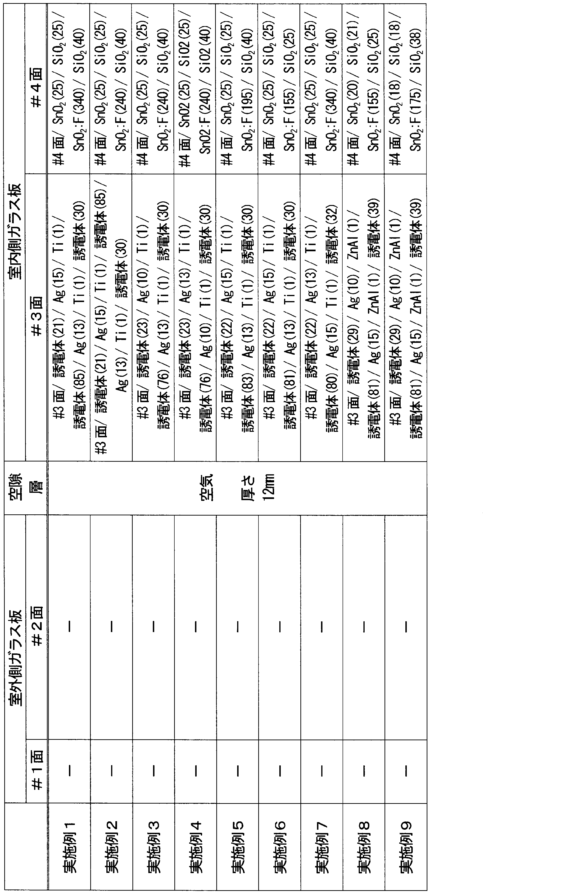
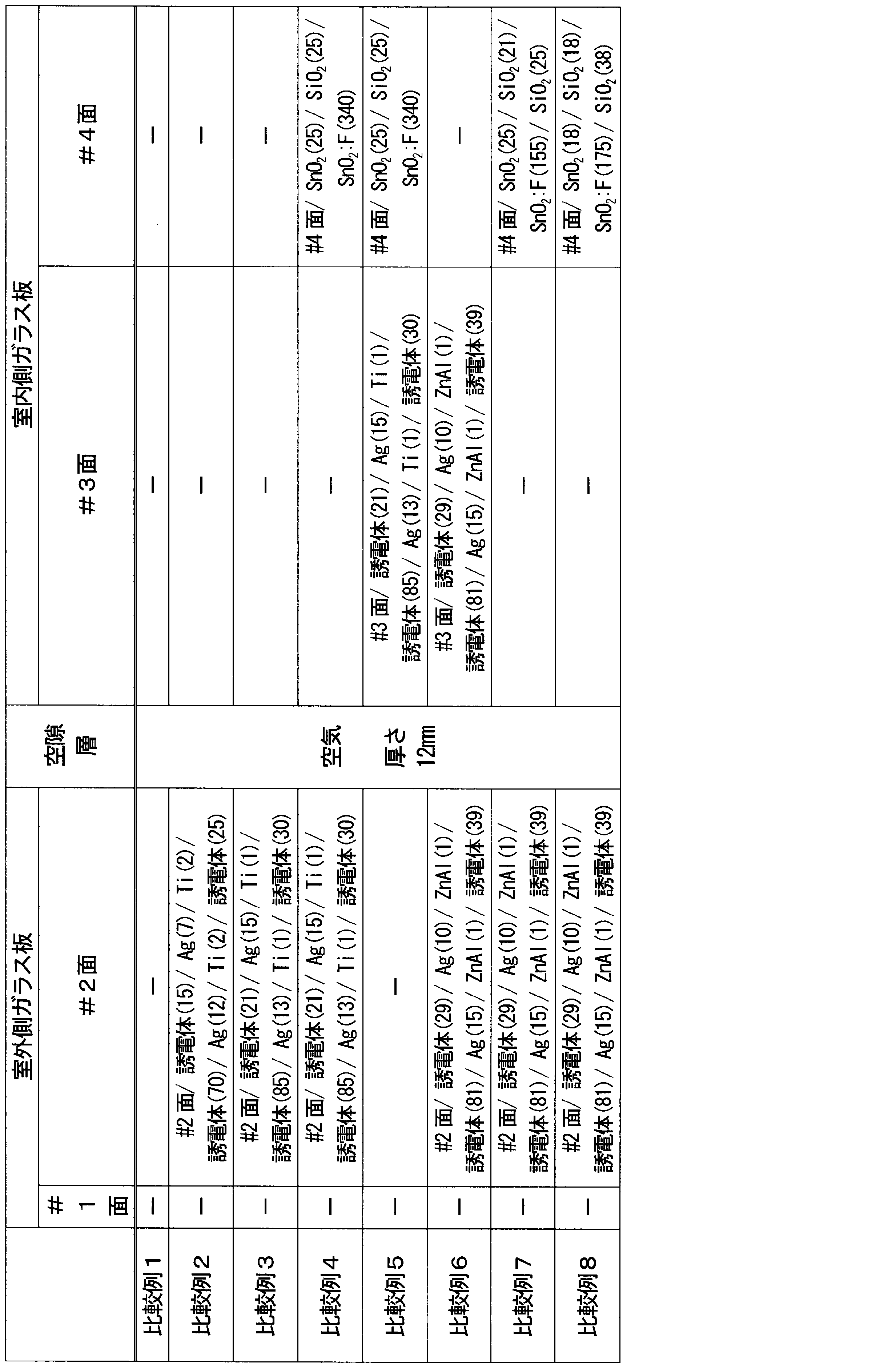
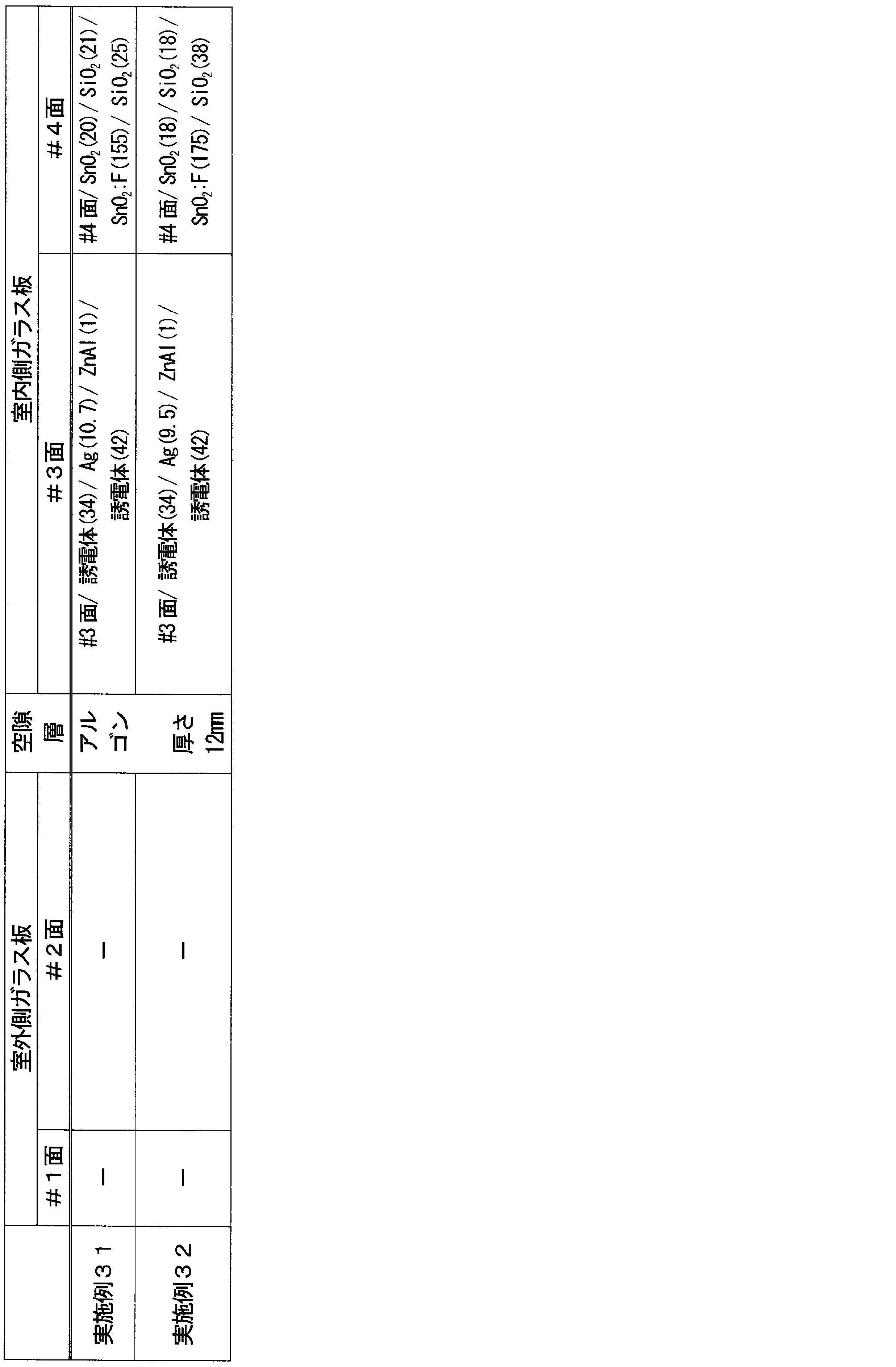
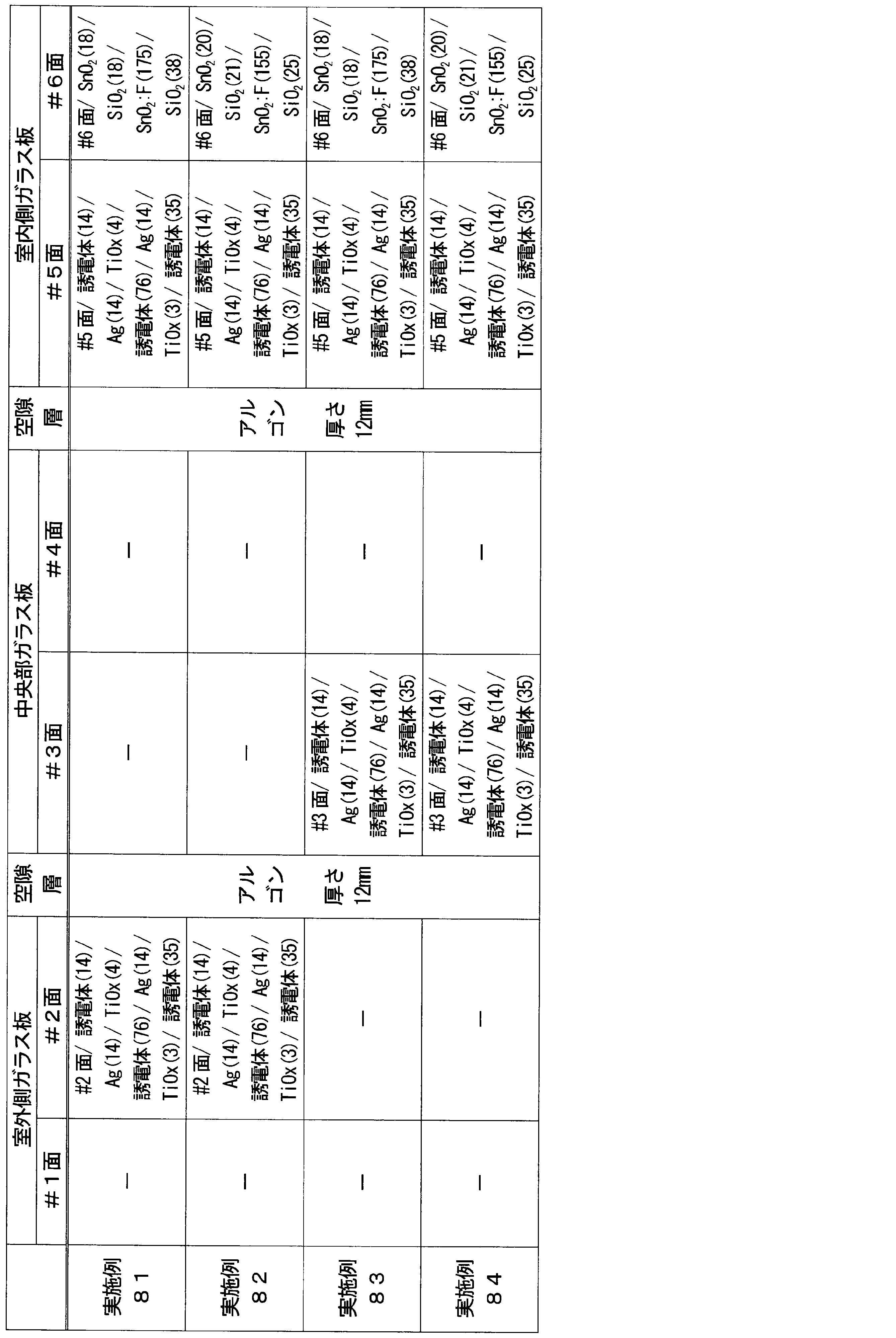
- the dielectric layer (“dielectric layer” shown in Tables 1A to 1M) in the Low-E film is a zinc oxide layer, a tin zinc oxide layer, a tin oxide layer, a silicon nitride layer, or the like. Titanium, ZnAl or titanium oxide (TiO x ) was used as the material constituting the sacrificial layer.
- the Low-E film including the transparent conductive oxide layer was formed by a CVD method.
- the visible light reflectance R (%) on 6 surfaces (multi-layer glass unit composed of three glass plates) and the SHGC value of the multi-layer glass unit are the values of the outdoor glass plate and the indoor glass plate, respectively. It calculated
- the incident angles on the # 1 surface and the # 4 surface (multilayer glass unit composed of two glass plates) or # 6 surface (multilayer glass unit composed of three glass plates) of the multilayer glass unit The reflection color at 5 ° was determined in accordance with JIS Z8722 and JIS Z8729 as the a * value and b * value of the La * b * color system.
- the a * value and the b * value at an incident angle of 45 ° were combined. Asked.
- the value of the reflected color at an incident angle of 45 ° was an average value of the measured value for S-polarized light and the measured value for P-polarized light in order to eliminate the influence of the polarization plane.
- the dirt removal property of the surface (# 4 surface or # 6 surface of the multilayer glass unit) exposed to the indoor space in the fabricated multilayer glass unit was evaluated as follows. First, a portion of the # 4 side or # 6 side where the following stains (fingerprints, oil-based ink, lipstick) are attached is rubbed a predetermined number of times with a 10 cm square cotton cloth soaked with a cleaning agent, and then the relevant portion. When exhalation was exhaled, the case where no trace of dirt was recognized with the naked eye was OK, and the case where it was recognized was judged as NG. The predetermined number of times was the number of rubbing until no trace was found on the cotton cloth in a commercially available float glass whose glass surface was not coated.
- Fingerprints were attached to the surface to be evaluated by pressing the fingertips of the hands.
- the cleaning agent was deionized water, and the predetermined number of times was 20 times.
- ⁇ Dirt removal characteristics for lipstick> On the surface to be evaluated, a commercially available lipstick (manufactured by Kanebo Cosmetics Co., Ltd.) was used to draw a circle having a diameter of about 1 cm, and dirt was adhered.
- the cleaning agent was a commercially available light removal solution (Nail Color Remover, Kanebo Cosmetics Co., Ltd.), and the predetermined number of times was 30.
- Glass plates may be fitted in buildings by being fitted into sashes.
- a glass plate receives solar radiation, it absorbs part of the solar radiation and the temperature rises and tries to expand.
- a portion fitted in a sash or a portion shaded by a wall of a building has a small temperature rise due to solar radiation and a small thermal expansion, and therefore restrains the expansion of the portion subjected to solar radiation.
- a tensile stress proportional to the temperature difference between the part that has been exposed to solar radiation and the part that is not, typically the peripheral part, is generated in the peripheral part of the glass plate. If the thermal stress exceeds the edge strength of the glass plate, the glass plate may be broken. This is called thermal cracking.
- the thermal stress generated in the glass plate changes as the temperature distribution of the glass changes depending on how the shadow is formed (shadow coefficient), and increases as the temperature in the center of the glass plate increases due to indoor curtains (curtain coefficient). ), Increases as the area of the glass plate increases (area factor), decreases as the thermal insulation of the sash into which the glass plate is fitted increases (edge coefficient, sash color), Change. For this reason, the thermal stress was calculated in consideration of these conditions. Specifically, pages 68-71 of the “Glass Building Materials Catalog Technical Document” published by Nippon Sheet Glass Co., Ltd.
- the shadow coefficient is “single shadow”
- the curtain coefficient is “no curtain”
- Thermal stress with edge coefficient as “elastic sealing material + backup material (foaming material)”
- sash color as "light color”
- the region as Japan's local "Southern Kanto, Hokuriku, Tokai, Kinki, China, Shikoku, Kyushu” If the calculated thermal stress exceeds the allowable stress of the float glass plate with a nominal thickness of 3 to 12 mm, there is a possibility of thermal cracking (YES), and if it falls below the allowable stress, there is no possibility of thermal cracking (NO) It was.
- Table 2A to Table 2G below show the evaluation results of the above characteristics for each of the multilayer glass units of the produced Examples and Comparative Examples.
- each of the glass plates is composed of two glass plates and has a 12 mm thick gap layer filled with air.
- a multi-layer glass unit was produced.
- Examples 11 to 17 and Examples 31 to 32 shown in Table 1C and Table 1E multilayer glass units having a 12 mm-thick gap layer made of two glass plates and filled with argon gas were produced. The characteristics of these multilayer glass units are shown in Tables 2A and 2B.
- the multi-layer glass units of Examples 1 to 9 show high dirt removal characteristics on the # 4 surface, and have no Low-E film, or Low-E film on only one surface. A low U value was exhibited with respect to the units of Comparative Examples 1 to 3 in which is formed.
- the multilayer glass units of Examples 1 to 9 showed a larger SHGC value than the units of Comparative Examples 4, 7, and 8 having Low-E films on the # 2 surface and the # 4 surface.
- both of the Low-E films formed on the two surfaces have two metal layers (Ag layers).
- the U value was higher and the SHGC value was smaller than the multilayer glass units of Examples 1 to 9.
- the multilayer glass units of Examples 1 to 9 exhibited higher stain removal characteristics on the # 4 surface than the units of Comparative Examples 4 and 5 in which Ra on the # 4 surface exceeded 14 nm.
- Example 1 the double-glazed units of Examples 1 and 7 showed lower U values.
- the sum of the thicknesses d3 and d4 of the Ag layer (metal layer) is 27 nm or more, but the above-mentioned ratio d4 / d3 relating to the thickness of the Ag layer (metal layer) is 1.
- the unit of Example 1 that is .15 or more has a reduced incident angle dependency of the reflected color compared to the unit of Example 7 that is not. More specifically, in Example 7, the a * value changes from a negative value to a positive value by changing the incident angle from 5 ° to 45 °, and the color tone of the reflected color changes from green to red.
- Example 1 the a * value remained a negative value even with the change in the incident angle, and the color tone of the reflected color maintained the green color.
- the units of Examples 8 and 9 in which the sum of the thicknesses of the Ag layers on the # 3 plane is less than 27 nm have a * values that are negative even when the incident angle changes, regardless of the above-described ratio d4 / d3.
- the color tone of the reflected color maintained a green color, that is, the incident angle dependence of the reflected color was relaxed.
- the units of Examples 3, 4, 8, and 9 in which the sum of the thicknesses of the Ag layer on the # 3 surface is less than 27 nm are larger than the units of Examples 1, 2, 5, and 7 that are not so. SHGC values are shown.
- Examples 11 to 17, Example 21 to 22 and Examples 31 to 32 shown in Table 2B also showed the same tendency as Examples 1 to 9 shown in Table 2A.
- the U values of Examples 21 to 22 are the same as those of Comparative Example 6, but the Low-E film having a metal layer is a film in which the film of Comparative Example 6 has two metal layers, that is, a film that is essentially excellent in low radiation.
- the configuration of Examples 21 to 22 achieves an excellent effect of reducing the U value. Recognize.
- the SHGC values of Examples 21 to 22 are higher than those of Comparative Examples 1 to 8.
- Examples 11 to 17 and Examples 31 to 32 having a gap layer of argon gas the same applies to the Low-E film compared to Examples 1 to 9 and Examples 21 to 22 having a gap layer of air. With the configuration, the U value was smaller.
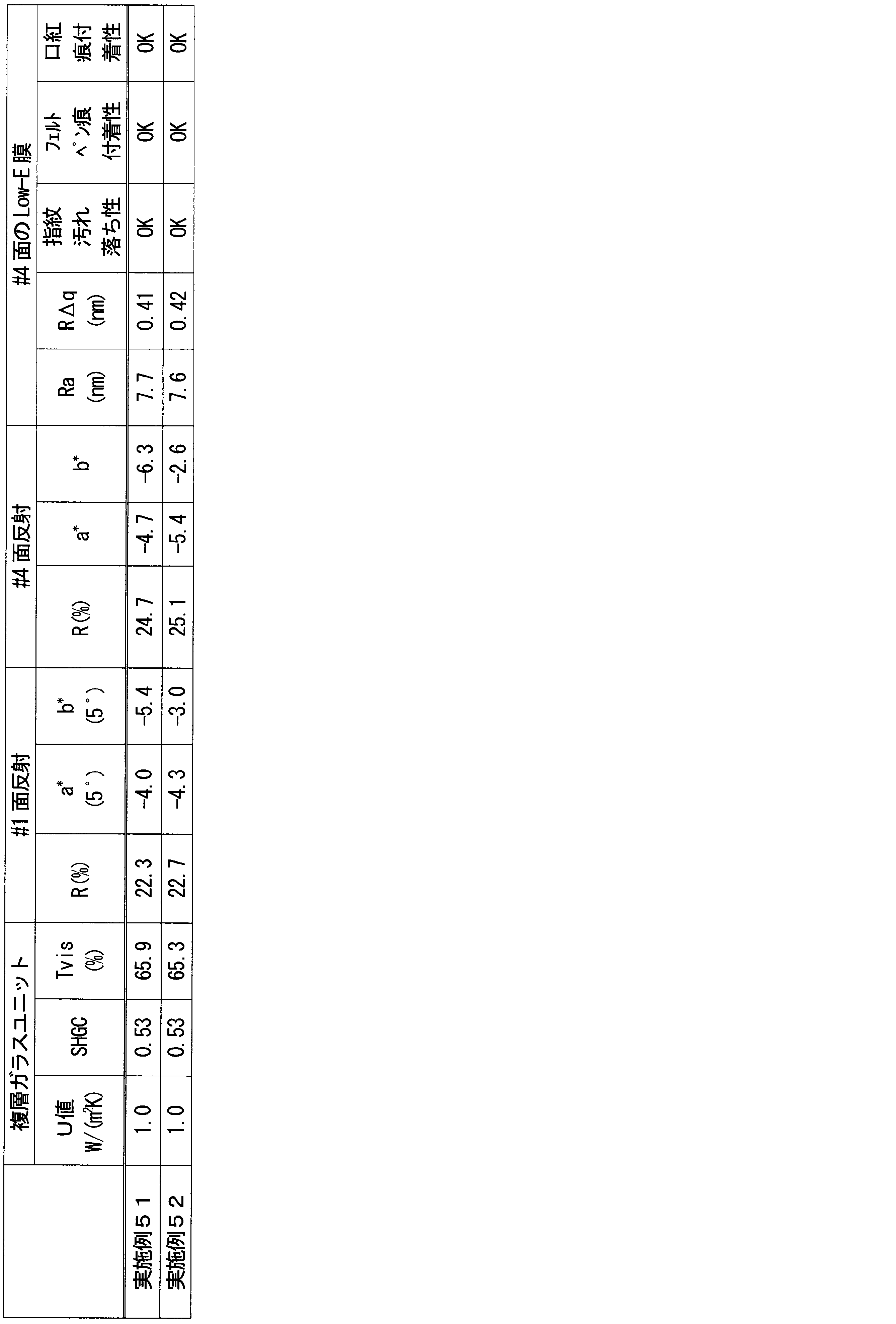
- Examples 41 to 42 Comparative Examples 41 to 44 and Examples 51 to 52 shown in Table 1F and Table 1G, a multilayer glass unit composed of two glass plates and having a vacuum gap layer having a thickness of 0.2 mm is used. Produced. The characteristics of these multilayer glass units are shown in Table 2C and Table 2D.
- Examples 41 to 42, Examples 51 to 52, and Comparative Examples 41 to 44 have the same tendency as Examples 1 to 9 and Comparative Examples 1 to 8 shown in Table 2A. Indicated. Also, in Examples 41 to 42 and Examples 51 to 52 having a vacuum gap layer, the Low-E is lower than the other examples including two glass plates having a gap layer of air or argon gas. The U value was even smaller when the membrane had a similar configuration. The U values of Examples 51 to 52 are higher than those of Comparative Examples 41 to 44. However, for the Low-E film having a metal layer, the films of Comparative Examples 41 to 44 have two metal layers. Considering that the film of ⁇ 52 has only one metal layer, it can be seen that the excellent effect of lowering the U value is achieved by the configuration of Examples 51-52.
- Examples 61 to 64 and Comparative Examples 61 to 64 shown in Table 1H and Table 1I a multilayer glass unit composed of three glass plates, one of which is a vacuum gap layer having a thickness of 0.2 mm, is manufactured. did. The properties of these double glazing units are shown in Table 2E.
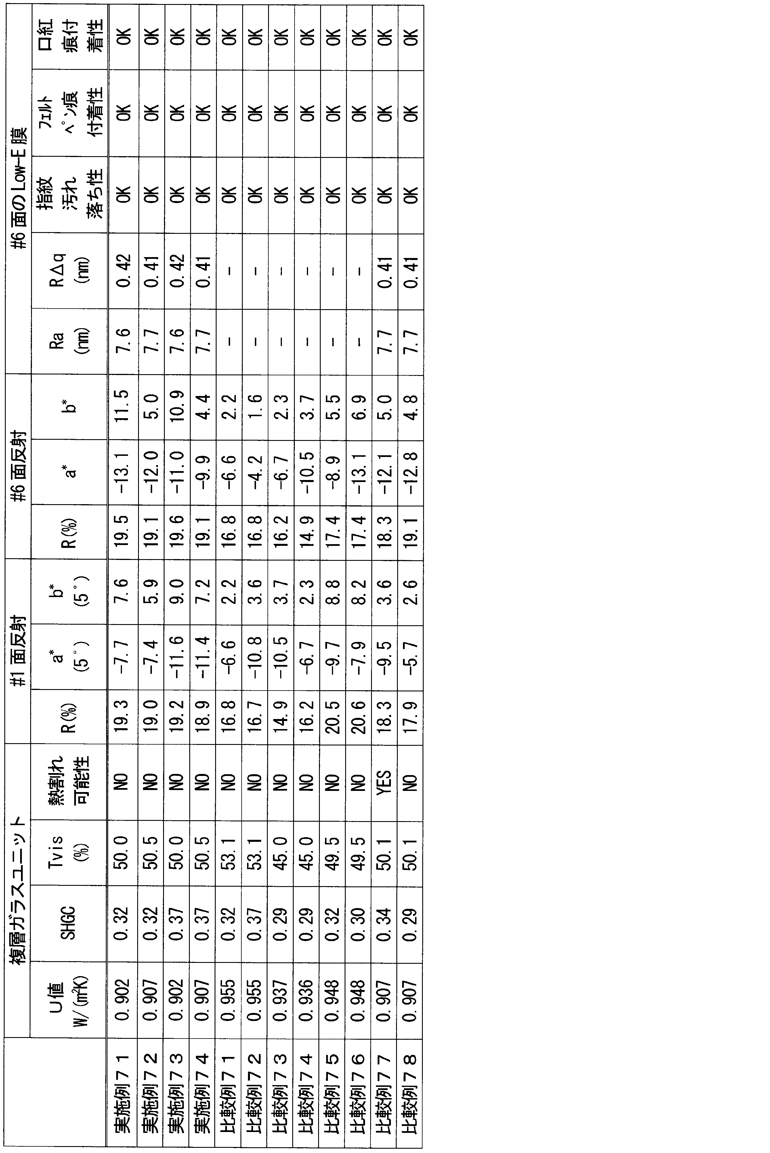
- Examples 71 to 74, Comparative Examples 71 to 78 and Examples 81 to 84 shown in Table 1J to Table 1M are composed of three glass plates, and both gap layers are filled with gas (air or argon). A layer glass unit was produced. The characteristics of these multilayer glass units are shown in Tables 2F and 2G.
- Comparative Example 78 is a unit in which three Low-E films are formed as in Examples 72 and 74, but the Low-E film is not formed on the main surfaces of both the # 5 plane and the # 6 plane. The U value does not change, but the SHGC value is small and inferior to each of the examples. Comparative Examples 73 and 74 have a large U value even though all of the three Low-E films have two metal layers, and only two of the three Low-E films have two metal layers. As compared with Examples 71 to 74 and Examples 81 to 84 having Also, compared to Comparative Examples 71 and 72, which are units having two Low-E films, Examples 71 to 74 and Examples 81 to 84 achieved very low U values.
- a float glass plate having a thickness of 3.0 mm which is the same as the glass plate used in the examples and comparative examples, was prepared and cut into predetermined dimensions, and as shown in Table 3 below, A Low-E film was formed only on one main plane. With respect to this glass plate on which the Low-E film was formed, only the roughness of the surface of the Low-E film and the stain removal property on the surface were evaluated without producing a multilayer glass unit. The results are shown in Table 3 as Comparative Examples 91 and 92.
- FIG. 5 shows the arithmetic average roughness Ra and the roughness curve on the # 4 surface of Examples 1 to 7 and Comparative Examples 4, 5, 91, and 92 (the formation surface of the Low-E film in Comparative Examples 91 and 92).
- the relationship with the root mean square slope R ⁇ q is shown.
- Ra and R ⁇ q show a good correlation between the examples and the comparative examples, but the correlation between Ra and R ⁇ q is poor between the examples and the comparative examples. That is, the Low-E film of the embodiment including the amorphous layer in the second laminated structure has a small R ⁇ q as compared to the Low-E film having the same Ra but no amorphous layer, and has high dirt removal characteristics. It can be said that it has.
- the multilayer glass unit of the present invention can be widely used for window structures such as buildings and vehicles.
Landscapes
- Chemical & Material Sciences (AREA)
- Engineering & Computer Science (AREA)
- Materials Engineering (AREA)
- Chemical Kinetics & Catalysis (AREA)
- General Chemical & Material Sciences (AREA)
- Geochemistry & Mineralogy (AREA)
- Life Sciences & Earth Sciences (AREA)
- Organic Chemistry (AREA)
- Civil Engineering (AREA)
- Structural Engineering (AREA)
- Securing Of Glass Panes Or The Like (AREA)
- Joining Of Glass To Other Materials (AREA)
- Surface Treatment Of Glass (AREA)
Abstract
Description
U値について、例えば1.6W/(m2・K)以下であり、ガラスユニットの構成によっては、1.4W/(m2・K)以下、および1.2W/(m2・K)以下;
SHGCの値について、例えば0.40以上であり、ガラスユニットの構成によっては、0.40を超える値、0.45以上、0.50以上、0.60以上。SHGCの値の上限は限定されない;
可視光線透過率(Tvis)について、例えば50~75%であり、好ましくは50~70%であり、より好ましくは50~65%;
室外空間からの反射率について、例えば8~26%であり、好ましくは10~20%であり、より好ましくは12~20%;
室内空間からの反射率について、例えば8~28%であり、好ましくは10~25%であり、より好ましくは10~22%。
U値について、例えば1.0W/(m2・K)以下であり、ガラスユニットの構成によっては、0.9W/(m2・K)以下;
SHGCの値について、例えば0.45以上であり、ガラスユニットの構成によっては、0.47以上、0.50以上。SHGCの値の上限は限定されない;
可視光線透過率(Tvis)について、例えば50~75%;
室外空間からの反射率について、例えば10~25%;
室内空間からの反射率について、例えば10~30%。
U値について、例えば0.93W/(m2・K)以下であり、ガラスユニットの構成によっては、0.80W/(m2・K)以下、0.72W/(m2・K)以下;
SHGCの値について、例えば0.30以上であり、ガラスユニットの構成によっては、0.32以上、0.36以上。SHGCの値の上限は限定されない;
可視光線透過率(Tvis)について、例えば45~60%;
室外空間からの反射率について、例えば15~25%;
室内空間からの反射率について、例えば15~25%。
U値について、例えば0.68W/(m2・K)以下であり、ガラスユニットの構成によっては、0.67W/(m2・K)以下、0.65W/(m2・K)以下;
SHGCの値について、例えば0.30以上であり、ガラスユニットの構成によっては、0.31以上。SHGCの値の上限は限定されない;
可視光線透過率(Tvis)について、例えば45~60%;
室外空間からの反射率について、例えば15~30%;
室内空間からの反射率について、例えば15~35%。
複層ガラスユニットの#1面における可視光透過率Tvis(%)、#1面における可視光反射率R(%)、#4面(2つのガラス板から構成される複層ガラスユニット)または#6面(3つのガラス板から構成される複層ガラスユニット)における可視光反射率R(%)、および複層ガラスユニットのSHGCの値は、室外側のガラス板および室内側のガラス板それぞれの光学特性実測値の結果から、JIS R3106(板ガラス類の透過率・反射率・放射率・日射熱取得率の試験方法)に準拠して計算により求めた。
複層ガラスユニットの#4面(2つのガラス板から構成される複層ガラスユニット)または#6面(3つのガラス板から構成される複層ガラスユニット)にLow-E膜を形成した実施例および比較例の一部について、当該Low-E膜の表面の算術平均粗さRaおよび粗さ曲線の二乗平均平方根傾斜RΔqを、JIS B0601:2013の規定に準拠して求めた。
作製した複層ガラスユニットにおける室内空間に露出している面(複層ガラスユニットの#4面または#6面)の汚れ落ち特性は、以下のように評価した。最初に、#4面または#6面における以下の各汚れ(指紋、油性インク、口紅)を付着させた部分を、洗浄剤を染み込ませた10cm角の綿布で所定の回数擦った後、当該部分に呼気を吐きかけたときに汚れの痕跡が肉眼で認められなかった場合をOK、認められた場合をNGとした。所定の回数は、ガラス面にコーティングがなされていない市販のフロートガラスにおいて、上記綿布で痕跡が認められなくなるまで擦った回数とした。
被評価表面に、手の指先を押しつけて指紋を付けた。洗浄剤は脱イオン水、所定の回数は20回とした。
被評価表面に、市販の黒色の油性フェルトペン(マジックインキ(R) No.500、寺西化学工業株式会社製)で直径約1cmの円を描き、乾燥させて汚れを付着させた。洗浄剤は市販のガラス用洗剤(ガラスマジックリン(R)、花王株式会社製)、所定の回数は50回とした。
被評価表面に、市販の口紅(株式会社カネボウ化粧品製)で直径約1cmの円を描き、汚れを付着させた。洗浄剤は市販の除光液(ネイルカラーリムーバー、株式会社カネボウ化粧品製)、所定の回数は30回とした。
3つのガラス板から構成される複層ガラスユニットのうち、実施例71~74、比較例71~78、および実施例81~84で作製したユニットについて、その中央部ガラス板の熱割れ可能性を評価した。









Claims (15)
- 所定の間隔で互いに離間した状態となるように空隙層を挟んで対向して配置された一対のガラス板を含み、室内空間と室外空間とを分離する複層ガラスユニットであって、
前記一対のガラス板のうち前記室内空間側に位置するガラス板における前記空隙層側の主平面に第1の低放射率(Low-E)膜、前記室内空間側の主平面に第2の低放射率膜が、それぞれ形成されており、
前記室内空間側の主平面に形成された前記第2の低放射率膜の表面の算術平均粗さRaが14nm以下である、複層ガラスユニット。 - 前記第1の低放射率膜は、金属層と、前記金属層における前記空隙層側の面に当該金属層と接して配置された犠牲層と、前記金属層および前記犠牲層を挟持する誘電体層のペアとを含む第1の積層構造、を有し、
前記第2の低放射率膜は、当該第2の低放射率膜が形成された前記主平面側から順に下地層、透明導電性酸化物層およびアモルファス層を含む第2の積層構造を有する、請求項1に記載の複層ガラスユニット。 - 前記アモルファス層の厚さが40nm未満である、請求項2に記載の複層ガラスユニット。
- 前記第2の低放射率膜について、
前記透明導電性酸化物層が、厚さ120nm以上のフッ素ドープ酸化スズ層を含み、
前記アモルファス層が、厚さ15~70nmのシリカ層を含み、
前記透明導電性酸化物層の厚さd1および前記アモルファス層の厚さd2は、式d2≧d1×0.11+1.4nmを満たし、
前記第2の低放射率膜の放射率εが0.34以下である、請求項2に記載の複層ガラスユニット。 - 前記第1の低放射率膜が2つの前記第1の積層構造を有する、請求項2に記載の複層ガラスユニット。
- 前記2つの第1の積層構造のうち、前記第1の低放射率膜が形成された前記主平面からより遠い当該構造が含む前記金属層の厚さd3に対する、当該主平面により近い当該構造が含む前記金属層の厚さd4の比d4/d3が1.15以上であり、
前記厚さd3が6nm以上である、請求項5に記載の複層ガラスユニット。 - 前記第2の低放射率膜の表面における粗さ曲線の二乗平均平方根傾斜RΔqが0.77以下である、請求項1に記載の複層ガラスユニット。
- 前記第2の低放射率膜が機能性層をさらに有する、請求項1に記載の複層ガラスユニット。
- 前記一対のガラス板のうち前記室外空間側に位置するガラス板の双方の主平面に低放射率(Low-E)膜が形成されていない、請求項1に記載の複層ガラスユニット。
- 前記複層ガラスユニットの厚さが22mm以下、U値が1.6(W/(m2・K))以下、SHGC値が0.4~0.7、可視光線透過率が50~75%である、請求項1に記載の複層ガラスユニット。
- 前記空隙層よりも前記室外空間側に、型板ガラス板または網入りガラス板を備える、請求項1に記載の複層ガラスユニット。
- 前記一対のガラス板のうち前記室外空間側に位置するガラス板に対して、所定の間隔で互いに離間した状態となるようにさらなる空隙層を挟んで対向して前記室外空間側に配置されたガラス板をさらに含む、請求項1に記載の複層ガラスユニット。
- 請求項1~12のいずれかに記載の複層ガラスユニットにおける、前記一対のガラス板のうち前記室内空間側に位置する前記ガラス板に用いるガラス板であって、
当該ガラス板の双方の主平面に、低放射率(Low-E)膜が形成されており、
一方の前記主平面に形成された前記低放射率膜の表面の算術平均粗さRaが14nm以下である、複層ガラスユニット用ガラス板。 - 前記一方の主平面に形成された前記低放射率膜の表面における粗さ曲線の二乗平均平方根傾斜RΔqが0.77以下である、請求項13に記載の複層ガラスユニット用ガラス板。
- 3つのガラス板A、ガラス板Bおよびガラス板Cから構成され、室内空間と室外空間とを分離する複層ガラスユニットであって、
前記ガラス板Aおよび前記ガラス板B、ならびに前記ガラス板Bおよび前記ガラス板Cは、それぞれ、所定の間隔で互いに離間した状態となるように空隙層を挟んで対向して配置され、
前記3つのガラス板のうち最も前記室内空間側に位置するガラス板における前記空隙層側の主平面に第1の低放射率(Low-E)膜、前記室内空間側の主平面に第2の低放射率膜が、それぞれ形成されているとともに、前記3つのガラス板のうち最も前記室外空間側に位置する前記ガラス板Aにおける前記ガラス板B側の主平面または中央の前記ガラス板Bにおける前記ガラス板A側の主平面に第3の低放射率膜が形成されており、
前記ガラス板Cの前記室内空間側の主平面に形成された前記第2の低放射率膜の表面の算術平均粗さRaが14nm以下である、複層ガラスユニット。
Priority Applications (6)
| Application Number | Priority Date | Filing Date | Title |
|---|---|---|---|
| EP19176236.8A EP3567201B1 (en) | 2014-06-11 | 2015-06-11 | Multi-layered glass unit and glass plate for multi-layered glass unit |
| JP2016527648A JP6546164B2 (ja) | 2014-06-11 | 2015-06-11 | 複層ガラスユニットおよび複層ガラスユニット用ガラス板 |
| US15/317,346 US10323453B2 (en) | 2014-06-11 | 2015-06-11 | Multiple-glazed glass unit and glass pane for multiple-glazed glass unit |
| EP19176239.2A EP3567202B1 (en) | 2014-06-11 | 2015-06-11 | Multiple-glazed glass unit |
| EP15806626.6A EP3156580B1 (en) | 2014-06-11 | 2015-06-11 | Multi-layered glass unit and glass plate for multi-layered glass unit |
| CN201580031115.XA CN106460447B (zh) | 2014-06-11 | 2015-06-11 | 多层玻璃单元以及多层玻璃单元用玻璃板 |
Applications Claiming Priority (2)
| Application Number | Priority Date | Filing Date | Title |
|---|---|---|---|
| JP2014120787 | 2014-06-11 | ||
| JP2014-120787 | 2014-06-11 |
Publications (1)
| Publication Number | Publication Date |
|---|---|
| WO2015190111A1 true WO2015190111A1 (ja) | 2015-12-17 |
Family
ID=54833222
Family Applications (1)
| Application Number | Title | Priority Date | Filing Date |
|---|---|---|---|
| PCT/JP2015/002946 Ceased WO2015190111A1 (ja) | 2014-06-11 | 2015-06-11 | 複層ガラスユニットおよび複層ガラスユニット用ガラス板 |
Country Status (5)
| Country | Link |
|---|---|
| US (1) | US10323453B2 (ja) |
| EP (3) | EP3567202B1 (ja) |
| JP (1) | JP6546164B2 (ja) |
| CN (3) | CN106460447B (ja) |
| WO (1) | WO2015190111A1 (ja) |
Cited By (12)
| Publication number | Priority date | Publication date | Assignee | Title |
|---|---|---|---|---|
| JP2017081787A (ja) * | 2015-10-29 | 2017-05-18 | セントラル硝子株式会社 | 複層ガラス |
| WO2017146770A1 (en) * | 2016-02-24 | 2017-08-31 | Vitro, S.A.B. De C.V. | Low emissivity coating for windows in cold climates |
| JP2018135260A (ja) * | 2017-02-07 | 2018-08-30 | ショット アクチエンゲゼルシャフトSchott AG | コーティングされた保護ウインドウ |
| JP2019019587A (ja) * | 2017-07-19 | 2019-02-07 | 旭ビルウォール株式会社 | 調光器内蔵トリプルガラス |
| WO2019139008A1 (ja) * | 2018-01-11 | 2019-07-18 | 日本板硝子株式会社 | 薄膜付き基材の製造方法及び薄膜付き基材 |
| CN111164269A (zh) * | 2017-10-12 | 2020-05-15 | 苹果公司 | 具有有源部件的透光面板 |
| JPWO2019176861A1 (ja) * | 2018-03-11 | 2021-02-25 | 日本板硝子株式会社 | 太陽電池パネル |
| US11015384B2 (en) | 2017-06-08 | 2021-05-25 | Apple Inc. | Light transmitting panel with active components |
| JP2021521082A (ja) * | 2018-04-12 | 2021-08-26 | エージーシー グラス ユーロップAgc Glass Europe | 多重グレージングユニット |
| JP2022553190A (ja) * | 2019-10-18 | 2022-12-22 | エージーシー グラス ユーロップ | 耐火真空断熱グレージング |
| JP2022553189A (ja) * | 2019-10-18 | 2022-12-22 | エージーシー グラス ユーロップ | 耐火真空断熱グレージング |
| JP2023029963A (ja) * | 2017-01-10 | 2023-03-07 | ユビキタス エナジー, インコーポレイテッド | 窓一体型透明光起電力モジュール |
Families Citing this family (10)
| Publication number | Priority date | Publication date | Assignee | Title |
|---|---|---|---|---|
| JP6760273B2 (ja) * | 2015-05-11 | 2020-09-23 | Agc株式会社 | 車両用の断熱ガラスユニット |
| EP3296277B1 (en) * | 2015-05-11 | 2021-01-13 | AGC Inc. | Heat insulating glass unit for vehicle and manufacturing method thereof |
| AU2018231143A1 (en) * | 2017-03-10 | 2019-10-31 | Guardian Glass, LLC | IG window unit having triple silver coating and dielectric coating on opposite sides of glass substrate |
| US20190345754A1 (en) * | 2018-05-09 | 2019-11-14 | Guardian Glass, LLC | Vacuum insulating glass (vig) window unit |
| FR3087382B1 (fr) * | 2018-10-18 | 2022-09-09 | Saint Gobain | Vitrage comprenant un revetement fonctionnel et un revetement absorbant d'ajustement colorimetrique |
| JP7661232B2 (ja) * | 2019-11-15 | 2025-04-14 | 日本板硝子株式会社 | ガラス体 |
| NL1043567B1 (nl) * | 2020-02-13 | 2021-09-15 | Autoglas D & K B V | Ruit en werkwijze voor het vervaardigen daarvan |
| WO2024112757A1 (en) * | 2022-11-23 | 2024-05-30 | LuxWall, Inc. | Vacuum insulated panel with passivation layer |
| US12410654B2 (en) | 2022-11-23 | 2025-09-09 | LuxWall, Inc. | Vacuum insulated panel with passivation layer |
| GB202416098D0 (en) * | 2024-10-31 | 2024-12-18 | Carbonfuturex Group Ltd | Multiple glazing |
Citations (3)
| Publication number | Priority date | Publication date | Assignee | Title |
|---|---|---|---|---|
| JP2010538960A (ja) * | 2007-09-14 | 2010-12-16 | 日本板硝子株式会社 | 低保守コーティングおよび低保守コーティングの製造方法 |
| JP2013517206A (ja) * | 2010-01-16 | 2013-05-16 | 日本板硝子株式会社 | 高品質放射制御コーティング、放射制御ガラスおよび製造方法 |
| JP2013227181A (ja) * | 2012-04-27 | 2013-11-07 | Asahi Glass Co Ltd | 封着構造体およびその製造方法 |
Family Cites Families (16)
| Publication number | Priority date | Publication date | Assignee | Title |
|---|---|---|---|---|
| CN1153749A (zh) * | 1995-11-02 | 1997-07-09 | 加迪安工业公司 | 中性高效耐久的低辐射率玻璃涂层体系、用其制造的隔热玻璃组件、及其制造方法 |
| FR2777782B1 (fr) * | 1998-04-22 | 2001-05-18 | Alexandre Marti | Solution pour la preparation d'une substance pharmaceutique pour le diagnostic et/ou le traitement de lesions tissulaires |
| US20030186064A1 (en) * | 2000-09-29 | 2003-10-02 | Kenji Murata | Transparent laminate having low emissivity |
| US7081302B2 (en) * | 2004-02-27 | 2006-07-25 | Centre Luxembourgeois De Recherches Pour Le Verre Et La Ceramique S.A. (C.R.V.C.) | Coated article with low-E coating including tin oxide interlayer |
| EP1858698B1 (en) * | 2005-02-24 | 2017-12-27 | Pilkington North America, Inc. | Anti-reflective, thermally insulated glazing articles |
| CN200958077Y (zh) * | 2006-10-19 | 2007-10-10 | 林嘉宏 | 可钢化低辐射镀膜玻璃 |
| CN101595073B (zh) * | 2007-09-14 | 2013-09-04 | 卡迪奈尔镀膜玻璃公司 | 低维护涂层和制造低维护涂层的方法 |
| GB0803574D0 (en) * | 2008-02-27 | 2008-04-02 | Pilkington Group Ltd | Coated glazing |
| FR2937366B1 (fr) * | 2008-10-17 | 2010-10-29 | Saint Gobain | Vitrage multiple incorporant au moins un revetement antireflet et utilisation d'un revetement antireflet dans un vitrage multiple |
| BE1019387A3 (fr) | 2010-06-24 | 2012-06-05 | Agc Glass Europe | Vitrage isolant. |
| GB201102735D0 (en) * | 2011-02-17 | 2011-03-30 | Pilkington Group Ltd | Coated glazing |
| FR2973023B1 (fr) * | 2011-03-25 | 2019-08-02 | Saint-Gobain Glass France | Vitrage multiple isolant comprenant deux empilements bas emissifs |
| BE1019988A3 (fr) * | 2011-05-24 | 2013-03-05 | Agc Glass Europe | Substrat verrier transparent portant un revetement de couches successives. |
| CN103561951A (zh) * | 2011-05-30 | 2014-02-05 | 旭硝子株式会社 | 低辐射率层叠体及多层玻璃 |
| US9332862B2 (en) * | 2012-11-30 | 2016-05-10 | Guardian Industries Corp. | Refrigerator door/window |
| US9499438B2 (en) * | 2013-02-28 | 2016-11-22 | Guardian Industries Corp. | Window for attenuating RF and IR electromagnetic signals |
-
2015
- 2015-06-11 CN CN201580031115.XA patent/CN106460447B/zh active Active
- 2015-06-11 CN CN201811381342.7A patent/CN109336410B/zh active Active
- 2015-06-11 EP EP19176239.2A patent/EP3567202B1/en active Active
- 2015-06-11 JP JP2016527648A patent/JP6546164B2/ja active Active
- 2015-06-11 CN CN201811381341.2A patent/CN109538075B/zh active Active
- 2015-06-11 US US15/317,346 patent/US10323453B2/en active Active
- 2015-06-11 EP EP19176236.8A patent/EP3567201B1/en active Active
- 2015-06-11 WO PCT/JP2015/002946 patent/WO2015190111A1/ja not_active Ceased
- 2015-06-11 EP EP15806626.6A patent/EP3156580B1/en active Active
Patent Citations (3)
| Publication number | Priority date | Publication date | Assignee | Title |
|---|---|---|---|---|
| JP2010538960A (ja) * | 2007-09-14 | 2010-12-16 | 日本板硝子株式会社 | 低保守コーティングおよび低保守コーティングの製造方法 |
| JP2013517206A (ja) * | 2010-01-16 | 2013-05-16 | 日本板硝子株式会社 | 高品質放射制御コーティング、放射制御ガラスおよび製造方法 |
| JP2013227181A (ja) * | 2012-04-27 | 2013-11-07 | Asahi Glass Co Ltd | 封着構造体およびその製造方法 |
Non-Patent Citations (1)
| Title |
|---|
| See also references of EP3156580A4 * |
Cited By (25)
| Publication number | Priority date | Publication date | Assignee | Title |
|---|---|---|---|---|
| JP2017081787A (ja) * | 2015-10-29 | 2017-05-18 | セントラル硝子株式会社 | 複層ガラス |
| CN109153602B (zh) * | 2016-02-24 | 2022-04-26 | 维特罗平板玻璃有限责任公司 | 寒冷气候下用于窗的低发射率涂层 |
| WO2017146770A1 (en) * | 2016-02-24 | 2017-08-31 | Vitro, S.A.B. De C.V. | Low emissivity coating for windows in cold climates |
| KR20180115745A (ko) * | 2016-02-24 | 2018-10-23 | 비트로 플랫 글래스 엘엘씨 | 한랭 기후에서의 창을 위한 저 방사율 코팅 |
| CN109153602A (zh) * | 2016-02-24 | 2019-01-04 | 维特罗平板玻璃有限责任公司 | 寒冷气候下用于窗的低发射率涂层 |
| JP2019509245A (ja) * | 2016-02-24 | 2019-04-04 | ビトロ フラット グラス エルエルシー | 寒い気候における窓のための低放射率被覆 |
| US10294149B2 (en) | 2016-02-24 | 2019-05-21 | VITRO S.A.B. de C.V. | Low emissivity coating for windows in cold climates |
| KR102170015B1 (ko) * | 2016-02-24 | 2020-10-26 | 비트로 플랫 글래스 엘엘씨 | 한랭 기후에서의 창을 위한 저 방사율 코팅 |
| JP2023029963A (ja) * | 2017-01-10 | 2023-03-07 | ユビキタス エナジー, インコーポレイテッド | 窓一体型透明光起電力モジュール |
| JP2018135260A (ja) * | 2017-02-07 | 2018-08-30 | ショット アクチエンゲゼルシャフトSchott AG | コーティングされた保護ウインドウ |
| JP7094114B2 (ja) | 2017-02-07 | 2022-07-01 | ショット アクチエンゲゼルシャフト | コーティングされた保護ウインドウ |
| US11319245B2 (en) | 2017-02-07 | 2022-05-03 | Schott Ag | Coated protective glazing |
| US11505987B2 (en) | 2017-06-08 | 2022-11-22 | Apple Inc. | Light transmitting panel with active components |
| US11015384B2 (en) | 2017-06-08 | 2021-05-25 | Apple Inc. | Light transmitting panel with active components |
| US11773642B2 (en) | 2017-06-08 | 2023-10-03 | Apple Inc. | Light transmitting panel with active components |
| JP2019019587A (ja) * | 2017-07-19 | 2019-02-07 | 旭ビルウォール株式会社 | 調光器内蔵トリプルガラス |
| CN111164269A (zh) * | 2017-10-12 | 2020-05-15 | 苹果公司 | 具有有源部件的透光面板 |
| JPWO2019139008A1 (ja) * | 2018-01-11 | 2020-12-24 | 日本板硝子株式会社 | 薄膜付き基材の製造方法及び薄膜付き基材 |
| WO2019139008A1 (ja) * | 2018-01-11 | 2019-07-18 | 日本板硝子株式会社 | 薄膜付き基材の製造方法及び薄膜付き基材 |
| JP7186184B2 (ja) | 2018-01-11 | 2022-12-08 | 日本板硝子株式会社 | 薄膜付き基材の製造方法及び薄膜付き基材 |
| JPWO2019176861A1 (ja) * | 2018-03-11 | 2021-02-25 | 日本板硝子株式会社 | 太陽電池パネル |
| JP2021521082A (ja) * | 2018-04-12 | 2021-08-26 | エージーシー グラス ユーロップAgc Glass Europe | 多重グレージングユニット |
| JP7385592B2 (ja) | 2018-04-12 | 2023-11-22 | エージーシー グラス ユーロップ | 多重グレージングユニット |
| JP2022553190A (ja) * | 2019-10-18 | 2022-12-22 | エージーシー グラス ユーロップ | 耐火真空断熱グレージング |
| JP2022553189A (ja) * | 2019-10-18 | 2022-12-22 | エージーシー グラス ユーロップ | 耐火真空断熱グレージング |
Also Published As
| Publication number | Publication date |
|---|---|
| EP3567201B1 (en) | 2023-04-19 |
| JP6546164B2 (ja) | 2019-07-17 |
| EP3567202B1 (en) | 2023-04-19 |
| EP3156580B1 (en) | 2019-07-10 |
| EP3156580A1 (en) | 2017-04-19 |
| JPWO2015190111A1 (ja) | 2017-04-20 |
| CN109336410A (zh) | 2019-02-15 |
| US20170114588A1 (en) | 2017-04-27 |
| EP3156580A4 (en) | 2017-12-06 |
| CN106460447A (zh) | 2017-02-22 |
| CN109538075A (zh) | 2019-03-29 |
| EP3567202A1 (en) | 2019-11-13 |
| CN109336410B (zh) | 2021-09-21 |
| EP3567201A1 (en) | 2019-11-13 |
| CN109538075B (zh) | 2020-06-26 |
| US10323453B2 (en) | 2019-06-18 |
| CN106460447B (zh) | 2018-12-11 |
Similar Documents
| Publication | Publication Date | Title |
|---|---|---|
| JP6546164B2 (ja) | 複層ガラスユニットおよび複層ガラスユニット用ガラス板 | |
| JP5792623B2 (ja) | 少なくとも1つの反射防止膜を組み込む多重窓ガラスユニット及び多重窓ガラスユニットにおける反射防止膜の使用 | |
| JP6034360B2 (ja) | 多層薄膜を有する透明基材 | |
| JP6090322B2 (ja) | 積層体 | |
| JP6781707B2 (ja) | 強化された太陽光制御性能を備えた太陽光制御コーティング | |
| JP5830011B2 (ja) | 高い太陽熱利得係数を有する太陽光制御コーティング | |
| JP5989802B2 (ja) | 減圧複層ガラスパネル | |
| JP6227637B2 (ja) | 低放射透明積層体およびそれを含む建築資材 | |
| KR20110104946A (ko) | 열 특성을 갖는 다층 스택 및 흡수 층을 구비한 기재 | |
| KR20110097939A (ko) | 열 특성을 갖는 다층 스택 및 흡수 층을 구비한 기재 | |
| KR101873103B1 (ko) | 창호용 기능성 건축 자재 | |
| CN111788162A (zh) | 具有四重金属性层的太阳控制涂层 | |
| US20240253330A1 (en) | Glazing for preventing bird collisions | |
| CN103443044A (zh) | 包括两个低辐射性叠层的隔离性多层窗玻璃 | |
| EP2862845A1 (en) | Low-emissivity transparent laminate, and method for manufacturing said low-emissivity transparent laminate and construction material including same | |
| KR20150058385A (ko) | 열적 특성을 갖는 스택 및 흡수 층이 제공된 기판 | |
| JP2019531497A (ja) | ジルコニウムに富む窒化ケイ素ジルコニウムを含む層を少なくとも1つ含む熱的特性を有する積層体を備えた基材、その使用及び製造 | |
| WO2012115111A1 (ja) | 積層体 | |
| US9416582B2 (en) | Insulating glazing | |
| JP7266020B2 (ja) | 複層ガラスパネル |
Legal Events
| Date | Code | Title | Description |
|---|---|---|---|
| 121 | Ep: the epo has been informed by wipo that ep was designated in this application |
Ref document number: 15806626 Country of ref document: EP Kind code of ref document: A1 |
|
| ENP | Entry into the national phase |
Ref document number: 2016527648 Country of ref document: JP Kind code of ref document: A |
|
| WWE | Wipo information: entry into national phase |
Ref document number: 15317346 Country of ref document: US |
|
| NENP | Non-entry into the national phase |
Ref country code: DE |
|
| REEP | Request for entry into the european phase |
Ref document number: 2015806626 Country of ref document: EP |
|
| WWE | Wipo information: entry into national phase |
Ref document number: 2015806626 Country of ref document: EP |