WO2015190145A1 - 防振装置 - Google Patents
防振装置 Download PDFInfo
- Publication number
- WO2015190145A1 WO2015190145A1 PCT/JP2015/057486 JP2015057486W WO2015190145A1 WO 2015190145 A1 WO2015190145 A1 WO 2015190145A1 JP 2015057486 W JP2015057486 W JP 2015057486W WO 2015190145 A1 WO2015190145 A1 WO 2015190145A1
- Authority
- WO
- WIPO (PCT)
- Prior art keywords
- axial direction
- movable member
- liquid chamber
- chamber
- vibration
- Prior art date
- Legal status (The legal status is an assumption and is not a legal conclusion. Google has not performed a legal analysis and makes no representation as to the accuracy of the status listed.)
- Ceased
Links
Images


Classifications
-
- F—MECHANICAL ENGINEERING; LIGHTING; HEATING; WEAPONS; BLASTING
- F16—ENGINEERING ELEMENTS AND UNITS; GENERAL MEASURES FOR PRODUCING AND MAINTAINING EFFECTIVE FUNCTIONING OF MACHINES OR INSTALLATIONS; THERMAL INSULATION IN GENERAL
- F16F—SPRINGS; SHOCK-ABSORBERS; MEANS FOR DAMPING VIBRATION
- F16F13/00—Units comprising springs of the non-fluid type as well as vibration-dampers, shock-absorbers, or fluid springs
- F16F13/04—Units comprising springs of the non-fluid type as well as vibration-dampers, shock-absorbers, or fluid springs comprising both a plastics spring and a damper, e.g. a friction damper
- F16F13/06—Units comprising springs of the non-fluid type as well as vibration-dampers, shock-absorbers, or fluid springs comprising both a plastics spring and a damper, e.g. a friction damper the damper being a fluid damper, e.g. the plastics spring not forming a part of the wall of the fluid chamber of the damper
- F16F13/08—Units comprising springs of the non-fluid type as well as vibration-dampers, shock-absorbers, or fluid springs comprising both a plastics spring and a damper, e.g. a friction damper the damper being a fluid damper, e.g. the plastics spring not forming a part of the wall of the fluid chamber of the damper the plastics spring forming at least a part of the wall of the fluid chamber of the damper
- F16F13/10—Units comprising springs of the non-fluid type as well as vibration-dampers, shock-absorbers, or fluid springs comprising both a plastics spring and a damper, e.g. a friction damper the damper being a fluid damper, e.g. the plastics spring not forming a part of the wall of the fluid chamber of the damper the plastics spring forming at least a part of the wall of the fluid chamber of the damper the wall being at least in part formed by a flexible membrane or the like
- F16F13/105—Units comprising springs of the non-fluid type as well as vibration-dampers, shock-absorbers, or fluid springs comprising both a plastics spring and a damper, e.g. a friction damper the damper being a fluid damper, e.g. the plastics spring not forming a part of the wall of the fluid chamber of the damper the plastics spring forming at least a part of the wall of the fluid chamber of the damper the wall being at least in part formed by a flexible membrane or the like characterised by features of partitions between two working chambers
- F16F13/107—Passage design between working chambers
-
- F—MECHANICAL ENGINEERING; LIGHTING; HEATING; WEAPONS; BLASTING
- F16—ENGINEERING ELEMENTS AND UNITS; GENERAL MEASURES FOR PRODUCING AND MAINTAINING EFFECTIVE FUNCTIONING OF MACHINES OR INSTALLATIONS; THERMAL INSULATION IN GENERAL
- F16F—SPRINGS; SHOCK-ABSORBERS; MEANS FOR DAMPING VIBRATION
- F16F13/00—Units comprising springs of the non-fluid type as well as vibration-dampers, shock-absorbers, or fluid springs
- F16F13/04—Units comprising springs of the non-fluid type as well as vibration-dampers, shock-absorbers, or fluid springs comprising both a plastics spring and a damper, e.g. a friction damper
- F16F13/06—Units comprising springs of the non-fluid type as well as vibration-dampers, shock-absorbers, or fluid springs comprising both a plastics spring and a damper, e.g. a friction damper the damper being a fluid damper, e.g. the plastics spring not forming a part of the wall of the fluid chamber of the damper
- F16F13/08—Units comprising springs of the non-fluid type as well as vibration-dampers, shock-absorbers, or fluid springs comprising both a plastics spring and a damper, e.g. a friction damper the damper being a fluid damper, e.g. the plastics spring not forming a part of the wall of the fluid chamber of the damper the plastics spring forming at least a part of the wall of the fluid chamber of the damper
- F16F13/10—Units comprising springs of the non-fluid type as well as vibration-dampers, shock-absorbers, or fluid springs comprising both a plastics spring and a damper, e.g. a friction damper the damper being a fluid damper, e.g. the plastics spring not forming a part of the wall of the fluid chamber of the damper the plastics spring forming at least a part of the wall of the fluid chamber of the damper the wall being at least in part formed by a flexible membrane or the like
- F16F13/105—Units comprising springs of the non-fluid type as well as vibration-dampers, shock-absorbers, or fluid springs comprising both a plastics spring and a damper, e.g. a friction damper the damper being a fluid damper, e.g. the plastics spring not forming a part of the wall of the fluid chamber of the damper the plastics spring forming at least a part of the wall of the fluid chamber of the damper the wall being at least in part formed by a flexible membrane or the like characterised by features of partitions between two working chambers
- F16F13/106—Design of constituent elastomeric parts, e.g. decoupling valve elements, or of immediate abutments therefor, e.g. cages
-
- F—MECHANICAL ENGINEERING; LIGHTING; HEATING; WEAPONS; BLASTING
- F16—ENGINEERING ELEMENTS AND UNITS; GENERAL MEASURES FOR PRODUCING AND MAINTAINING EFFECTIVE FUNCTIONING OF MACHINES OR INSTALLATIONS; THERMAL INSULATION IN GENERAL
- F16F—SPRINGS; SHOCK-ABSORBERS; MEANS FOR DAMPING VIBRATION
- F16F13/00—Units comprising springs of the non-fluid type as well as vibration-dampers, shock-absorbers, or fluid springs
- F16F13/04—Units comprising springs of the non-fluid type as well as vibration-dampers, shock-absorbers, or fluid springs comprising both a plastics spring and a damper, e.g. a friction damper
- F16F13/06—Units comprising springs of the non-fluid type as well as vibration-dampers, shock-absorbers, or fluid springs comprising both a plastics spring and a damper, e.g. a friction damper the damper being a fluid damper, e.g. the plastics spring not forming a part of the wall of the fluid chamber of the damper
- F16F13/08—Units comprising springs of the non-fluid type as well as vibration-dampers, shock-absorbers, or fluid springs comprising both a plastics spring and a damper, e.g. a friction damper the damper being a fluid damper, e.g. the plastics spring not forming a part of the wall of the fluid chamber of the damper the plastics spring forming at least a part of the wall of the fluid chamber of the damper
- F16F13/10—Units comprising springs of the non-fluid type as well as vibration-dampers, shock-absorbers, or fluid springs comprising both a plastics spring and a damper, e.g. a friction damper the damper being a fluid damper, e.g. the plastics spring not forming a part of the wall of the fluid chamber of the damper the plastics spring forming at least a part of the wall of the fluid chamber of the damper the wall being at least in part formed by a flexible membrane or the like
Definitions
- the present invention relates to a vibration isolator that is applied to, for example, automobiles and industrial machines and absorbs and attenuates vibrations of a vibration generating unit such as an engine.
- This application claims priority based on Japanese Patent Application No. 2014-122439 for which it applied to Japan on June 13, 2014, and uses the content here.
- the vibration isolator includes a cylindrical first mounting member connected to one of the vibration generating unit and the vibration receiving unit, a second mounting member connected to the other, and an elastic connecting the both mounting members.
- a partition member that divides the body and the liquid chamber in the first mounting member in which the liquid is sealed into a main liquid chamber and a sub liquid chamber whose elastic body is a part of the wall surface, and the partition member And a movable member housed in the housing chamber so as to be deformable in the axial direction of the first mounting member.
- the partition member has a plurality of communication holes that extend from the portion facing the movable member in the axial direction on the wall surface of the storage chamber toward the outside in the axial direction and communicate with the storage chamber and the main liquid chamber or the sub liquid chamber, respectively. Is provided. Of the plurality of communication holes, the communication hole that connects the storage chamber and the main liquid chamber directly connects the storage chamber and the main liquid chamber in the axial direction.
- the movable member deforms in the axial direction and comes into contact with the wall surface of the storage chamber. For example, there is a problem that a large abnormal noise occurs due to vibration of the partition member.
- the present invention has been made in view of the above-described circumstances, and an object thereof is to suppress an abnormal noise that is generated at the time of input from a vibration generating unit.
- the vibration isolator includes a cylindrical first attachment member connected to one of the vibration generating portion and the vibration receiving portion, a second attachment member connected to the other, and both of these attachment members.
- a partition member that partitions an elastic body to be connected, a liquid chamber in the first mounting member in which the liquid is sealed, into a main liquid chamber having the elastic body as a part of a wall surface and a sub liquid chamber; and a partition member And a movable member accommodated in the accommodating chamber so as to be deformable or displaceable in the axial direction of the first mounting member, and the partition member is a portion facing the movable member in the axial direction on the wall surface of the accommodating chamber
- a plurality of communication holes that extend outward in the axial direction and communicate with the storage chamber and the main liquid chamber or the sub liquid chamber, respectively, and at least one of the plurality of communication holes includes a storage chamber and A direct connection hole that connects the main liquid chamber or sub-liquid chamber directly in the axial direction.
- the vibration control device further includes a current control member that is positioned outside the direct connection hole in the axial direction and is disposed so as to overlap the movable member in the axial direction through the direct connection hole.
- the liquid pressure in the main liquid chamber fluctuates based on the input from the vibration generating unit and a pressure difference occurs between the main liquid chamber and the sub liquid chamber, the movement of the liquid in the main liquid chamber or the sub liquid chamber A pressure is exerted on the movable member through the direct connection hole.
- the dynamic pressure is not directly exerted on the movable member, but is exerted on the movable member via the flow restricting member, and the direction and magnitude of the pressure gradient of the liquid around the movable member is controlled by the flow restricting member. Can be changed.
- the movable member when the movable member is deformed or displaced in the axial direction and comes into contact with the wall surface of the storage chamber, for example, the kinetic energy of the movable member can be suppressed by suppressing the deformation speed or the displacement speed of the movable member.
- the movable member since the movable member does not contact the flow restricting member, it is possible to suppress abnormal noise.
- the movable member includes a fixed portion fixed in the axial direction with respect to the partition member, and is formed to be deformable in the axial direction, and the flow restricting member is an exposed region that is exposed in the axial direction from the direct connection hole in the movable member.
- the partition member may overlap with the portion farthest from the fixed portion in the axial direction.
- the movable member since the movable member includes the fixed portion, the portion of the movable member that is separated from the fixed portion in the plan view is more easily deformed in the axial direction.
- the flow restricting member overlaps in the axial direction with the portion of the exposed region of the movable member that is farthest from the fixed portion in the plan view, the portion of the exposed region that is most easily deformed in the axial direction.
- the dynamic pressure of the liquid can be prevented from being exerted directly. Thereby, abnormal noise can be suppressed effectively.
- the exposed region is disposed on the hole axis of the direct connection hole, and a fixed portion is provided in a portion other than the exposed region, and the current control member sandwiches the hole shaft in the exposed region.
- the portion positioned on the opposite side of the fixed portion may overlap the axial direction and extend in a direction along the hole axis.
- the flow restricting member is overlapped in the axial direction with a portion of the exposed region of the movable member that is located on the opposite side of the fixed portion with the hole axis of the direct connection hole interposed therebetween, and the direction along the hole axis It extends to.
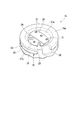
- FIG. 1 It is a longitudinal cross-sectional view of the vibration isolator which concerns on one Embodiment of this invention. It is a perspective view of the partition member which comprises the vibration isolator shown in FIG. It is an enlarged view of the principal part in the vibration isolator shown in FIG.
- the vibration isolator 10 includes a cylindrical first mounting member 11 connected to one of a vibration generating unit and a vibration receiving unit, and a second mounting member 12 connected to the other.
- An elastic body 13 that elastically connects the first mounting member 11 and the second mounting member 12, and a liquid chamber 16 that is disposed inside the first mounting member 11 and formed inside the first mounting member 11.
- the partition member 15 is provided to partition the main liquid chamber 16a and the sub liquid chamber 16b.
- each of these members is provided coaxially with the central axis O.
- a direction along the central axis O is referred to as an axial direction (an axial direction of the first mounting member)
- a direction orthogonal to the central axis O is referred to as a radial direction
- a direction around the central axis O is referred to as a circumferential direction.
- the liquid chamber 16 is divided into the main liquid chamber 16a on one side in the axial direction (upper side in FIG. 1) and the other side in the axial direction (in FIG. 1) by the partition member 15. It is divided into a sub-liquid chamber 16b on the lower side.
- the main liquid chamber 16a and the sub liquid chamber 16b are filled with a liquid L such as ethylene glycol, water, or silicone oil.
- the vibration isolator 10 is attached to, for example, an automobile and suppresses transmission of engine vibration to the vehicle body.
- the second mounting member 12 is connected to an engine (not shown) as a vibration generating unit, while the first mounting member 11 is connected to a vehicle body as a vibration receiving unit via a bracket (not shown).
- the first mounting member 11 connects the first cylinder part 11a formed on one axial side, the second cylinder part 11b formed on the other axial side, and the first cylinder part 11a and the second cylinder part 11b. And a stepped portion 11c.
- the first cylinder part 11a, the second cylinder part 11b, and the step part 11c are arranged coaxially with the central axis O and are integrally formed.
- One end of the first mounting member 11 in the axial direction is closed in a liquid-tight state by the elastic body 13, and the other end in the axial direction of the first mounting member 11 is closed in a liquid-tight state by the diaphragm 14.
- the second mounting member 12 is disposed on one axial side of the first cylindrical member 11 a of the first mounting member 11.
- the elastic body 13 is a member made of, for example, a rubber material.
- the elastic body 13 protrudes from one end in the axial direction of the first mounting member 11 toward one side in the axial direction, and has a truncated cone-shaped deformed portion 13a that is gradually reduced in diameter toward the one side in the axial direction.
- a covering portion 13b extending from the deformable portion 13a toward the other side in the axial direction along the inner peripheral surface of the first mounting member 11 is provided.
- the covering portion 13b is vulcanized and bonded to the inner peripheral surface of the first mounting member 11, and the inner peripheral surface of the first mounting member 11 is covered with the elastic body 13 over the entire area.
- the deformation portion 13a and the covering portion 13b are integrally formed.
- the partition member 15 is integrally formed of, for example, an aluminum alloy or a resin.
- the partition member 15 is formed in a disk shape and is fitted in the first attachment member 11 (in the covering portion 13b).
- the first outer end face 15a facing the one side in the axial direction of the partition member 15 faces the main liquid chamber 16a, and the partition member 15 forms a part of the partition wall of the main liquid chamber 16a.
- the second outer end surface 15b facing the other side in the axial direction faces the sub liquid chamber 16b side, and the partition member 15 forms a part of the partition wall of the sub liquid chamber 16b.
- the first outer end surface 15a and the second outer end surface 15b are formed with recesses 17a and 17b that are recessed inward in the axial direction.
- the first recess 17a which is a recess formed in the first outer end surface 15a
- the second recess 17b which is a recess formed in the second outer end surface 15b, are both arranged coaxially with the central axis O.
- the partition member 15 is provided with a storage chamber 18, a lightening portion 19, and a restriction passage 20.
- the storage chamber 18, the lightening portion 19 and the restriction passage 20 are independent of each other.
- the storage chamber 18 is located between the first recess 17a and the second recess 17b along the axial direction.
- the storage chamber 18 is arranged to be shifted with respect to the central axis O.
- the storage chamber 18 intersects the central axis O while being eccentric with respect to the central axis O.
- a part of the storage chamber 18 in the circumferential direction opens from the outer peripheral surface of the partition member 15 to the outside in the radial direction, and the remaining part in the circumferential direction is closed from the outside in the radial direction.
- the storage chamber 18 is provided with an opening 21 that opens outward in the radial direction, and a closing portion 22 that is located on the opposite side of the opening 21 with the central axis O in between. .
- the blocking portion 22 is sandwiched in the axial direction between the first concave portion 17a and the second concave portion 17b.
- the size of the storage chamber 18 in the axial direction differs for each position in the front-rear direction along the opening axis of the opening 21.
- the storage chamber 18 gradually decreases in the axial direction from the rear side on the opening 21 side toward the front side on the closing portion 22 side in the front-rear direction.
- both end surfaces 18 a and 18 b facing inward in the axial direction are inclined with respect to the central axis O.
- the first inner end face 18a located on the main liquid chamber 16a side gradually extends toward the lower side (the other side in the axial direction) toward the front side, and is located on the sub liquid chamber 16b side.
- the second inner end face 18b that extends gradually extends toward the upper side (one side in the axial direction) toward the front side.
- the lightening portion 19 is recessed from the second concave portion 17b toward the one side in the axial direction, and is disposed so as to avoid the accommodating chamber 18.
- the restriction passage 20 communicates the main liquid chamber 16a and the sub liquid chamber 16b.
- the restriction passage 20 extends along the circumferential direction on the outer peripheral surface of the partition member 15, and is disposed so as to avoid the storage chamber 18 and the lightening portion 19.
- the restriction passage 20 is tuned so that resonance (liquid column resonance) occurs when an engine shake vibration having a frequency of about 10 Hz is input, for example.
- a movable member 23 (movable plate, membrane) is disposed in the storage chamber 18.
- the movable member 23 is accommodated in the storage chamber 18 so as to be deformable in the axial direction.
- the movable member 23 is accommodated in the storage chamber 18 by being inserted into the storage chamber 18 from the opening 21 of the storage chamber 18 toward the front side in the front-rear direction, for example.
- the movable member 23 is formed in a plate shape whose front and back surfaces are directed in the axial direction by, for example, a rubber material, and can be elastically deformed.
- the movable member 23 is deformed in the axial direction according to the pressure difference between the main liquid chamber 16a and the sub liquid chamber 16b.
- the movable member 23 has a similar shape to the storage chamber 18.
- the thickness which is the size of the movable member 23 in the axial direction, gradually decreases toward the front side in the front-rear direction.
- the rear end portion in the front-rear direction is a fixed end portion 24 (fixed portion) fixed in the axial direction with respect to the partition member 15.
- the fixed end 24 is fitted in the opening 21 in a liquid-tight manner over the entire circumference of the opening 21 and restricts leakage of the liquid L in the storage chamber 18 from the opening 21.
- a gap is provided across the entire area between the deformable portion 25 located on the front side of the fixed end 24 in the movable member 23 and the wall surface of the storage chamber 18.
- a gap in the axial direction is provided between both surfaces of the movable member 23 facing in the axial direction and both end faces 18a, 18b of the storage chamber 18.
- the front end of the movable member 23 in the front-rear direction is a free end 26 that is farthest from the fixed end 24 in a plan view of the partition member 15 viewed from the axial direction.
- the free end portion 26 is an end portion on the opposite side of the fixed end portion 24 in the movable member 23.
- the partition member 15 is further provided with a plurality of communication holes 27a and 27b (direct connection holes).
- the plurality of communication holes 27a and 27b extend from the portion facing the movable member 23 in the axial direction on the wall surface of the storage chamber 18 toward the outside in the axial direction, and the storage chamber 18 and the main liquid chamber 16a or sub liquid chamber 16b , Communicate with each other.
- the first communication hole 27a directly connects the storage chamber 18 and the main liquid chamber 16a in the axial direction, and opens in the main liquid chamber 16a toward the outside in the axial direction.
- One first communication hole 27a is provided.
- the first communication hole 27a is provided on the bottom surface of the first recess 17a.
- the hole axis O1 of the first communication hole 27a is shifted with respect to the central axis O.
- the first communication hole 27 a is larger in the axial direction than the axial gap between the surface of the movable member 23 and the first inner end surface 18 a of the storage chamber 18.
- the first communication hole 27a is such that a portion of the deformable portion 25 of the movable member 23 located on the rear side of the free end portion 26 is exposed in the axial direction toward the main liquid chamber 16a, and the fixed end portion 24 is Not exposed.
- the movable member 23 is exposed over the entire first communication hole 27a, and the exposed region 28 of the movable member 23 that is exposed in the axial direction from the first communication hole 27a is disposed on the hole axis O1 of the first communication hole 27a. Has been.
- a restricting portion 29 protrudes from the inner peripheral surface of the first communication hole 27a.
- the restricting portion 29 prevents the movable member 23 from being detached from the storage chamber 18 through the first communication hole 27a.
- the restricting portion 29 contacts the deformed movable member 23 and restricts further deformation of the movable member 23.
- a plurality of restricting portions 29 are arranged at intervals in a direction along the hole axis O1 of the first communication hole 27a. The restricting portion 29 does not protrude outward in the axial direction from the first communication hole 27a.
- a plurality of second communication holes 27b are provided. All the second communication holes 27b directly connect the storage chamber 18 and the auxiliary liquid chamber 16b in the axial direction, and open toward the outside in the axial direction in the auxiliary liquid chamber 16b.
- the plurality of second communication holes 27b are provided at intervals on the bottom surface of the second recess 17b.
- the second communication hole 27b exposes, in the deformed portion 25 of the movable member 23, a portion located on the rear side of the free end portion 26 in the axial direction toward the sub liquid chamber 16b.
- the second communication hole 27 b is larger in the axial direction than the axial gap between the surface of the movable member 23 and the second inner end surface 18 b of the storage chamber 18.
- the vibration isolator 10 is further provided with a current control member 30 (a current control plate).
- the flow restricting member 30 is located outside the first communication hole 27a in the axial direction, and is disposed so as to overlap the movable member 23 in the axial direction through the first communication hole 27a.
- the front and back surfaces of the flow control member 30 are formed in a plate shape facing the axial direction.
- the flow restricting member 30 is formed of a rigid body and has the same degree of rigidity as the partition member 15. The rigidity of the flow restricting member 30 is set to such an extent that the flow restricting member 30 is not deformed when the dynamic pressure of the liquid L acts on the flow restricting member 30 based on the input from the vibration generating unit, for example. Yes.
- the flow restricting member 30 is disposed in the first recess 17 a and is fixed to the partition member 17.
- the current control member 30 is smaller in the axial direction than the first recess 17a and the first communication hole 27a.
- the current regulating member 30 is fixed on the bottom surface of the first recess 17a and is accommodated in the first recess 17a.
- the flow restricting member 30 overlaps the portion of the exposed region 28 of the movable member 23 that is farthest from the fixed end portion 24 in the plan view in the axial direction.
- the flow restricting member 30 is overlapped in the axial direction with a portion of the exposed region 28 positioned on the front side (opposite side of the fixed end 24 with the hole axis O1 of the first communication hole 27a in between), and It extends in a direction along the hole axis O1 of the one communication hole 27a.
- the flow restricting member 30 extends continuously around the hole axis O1 and covers a portion of the exposed region 28 of the movable member 23 located on the front side over the entire length around the hole axis O1.
- a part of the flow restricting member 30 covers the exposed region 28 of the movable member 23 in the axial direction, and the remaining part is fixed to the partition member 15.
- the rear portion located on the rear side of the current control member 30 covers the exposed region 28 in the axial direction, and the front portion located on the front side is fixed to the bottom surface of the first recess 17a.
- the front portion of the flow restricting member 30 is fixed to the bottom surface of the first concave portion 17a by a bolt 31.
- the rear portion of the flow restricting member 30 is adjacent to the first communication hole 27a in the axial direction.
- the rear part of the flow restricting member 30 is not in contact with the movable member 23 deformed in the axial direction when the liquid pressure in the main liquid chamber 16a varies based on the input from the vibration generating part. Regulating member 30 is separated from movable member 23 regardless of whether there is an input from the vibration generating portion.
- vibration having a minute amplitude for example, ⁇ 0.2 mm or less
- idle vibration having a frequency of around 30 Hz acts on the vibration isolator 10 and the pressure of the liquid L in the main liquid chamber 16a fluctuates.
- the movable member 23 is deformed in the axial direction in the storage chamber 18. Thereby, vibration can be absorbed and attenuated.
- vibration having a larger amplitude than the above-described minute amplitude acts on the vibration isolator 10 and the pressure of the liquid L in the main liquid chamber 16a fluctuates.
- the movable member 23 comes into contact with the both end surfaces 18a and 18b of the storage chamber 18 in the partition member 15 and closes the communication holes 27a and 27b.
- the liquid L flows between the main liquid chamber 16a and the sub liquid chamber 16b through the restriction passage 20, and liquid column resonance occurs, so that vibration can be absorbed and attenuated.
- the liquid pressure in the main liquid chamber 16a varies based on the input from the vibration generating unit, and the main liquid chamber 16a and the sub liquid chamber 16b When a pressure difference occurs between them, the dynamic pressure of the liquid L in the main liquid chamber 16a is exerted on the movable member 23 through the first communication hole 27a. At this time, as shown by an arrow in FIG. 3, the dynamic pressure is not directly exerted on the movable member 23, but is exerted on the movable member 23 via the flow restricting member 30. The direction and magnitude of the pressure gradient of the liquid L around 23 are changed.
- the movable member 23 when the movable member 23 is deformed in the axial direction and abuts against the wall surface of the storage chamber 18, for example, the kinetic energy of the movable member 23 can be suppressed by suppressing the deformation speed of the movable member 23.
- the movable member 23 since the movable member 23 does not contact the flow restricting member 30, abnormal noise can be suppressed.
- it is possible to suppress noise by simply providing the flow restricting member 30 as described above, and the size of the communication holes 27a and 27b and the positional relationship between the partition member 15 and the movable member 23 can be changed without changing. The sound can be suppressed. Therefore, it is possible to suppress abnormal noise while suppressing influences on the characteristics of the vibration isolator 10, such as frequency characteristics, attenuation characteristics, and cavitation characteristics.
- the movable member 23 since the movable member 23 includes the fixed end portion 24, the portion of the movable member 23 that is separated from the fixed end portion 24 in the plan view is more easily deformed in the axial direction.
- the flow restricting member 30 overlaps the portion of the exposed region 28 of the movable member 23 that is farthest from the fixed end 24 in the plan view in the axial direction, the axial direction of the exposed region 28 is the most axial direction. It is possible to prevent the dynamic pressure of the liquid L from being directly applied to the portion that is easily deformed. Thereby, abnormal noise can be suppressed effectively.
- the flow restricting member 30 overlaps with the portion located on the front side in the exposed region 28 of the movable member 23 in the axial direction, and extends in a direction along the hole axis O1 of the first communication hole 27a. Thereby, it becomes possible to cover the part which is easily deformed in the axial direction in the exposed region 28 of the movable member 23 with the current control member 30 over a wide range, and it is possible to more effectively suppress the noise.
- the first concave portion 17a, the second concave portion 17b, the lightening portion 19 and the restriction passage 20 are provided, but these may be omitted.
- the flow restricting member 30 overlaps the portion of the exposed region 28 of the movable member 23 that is farthest from the fixed end 24 in the plan view in the axial direction, but the present invention is not limited to this. I can't.
- the current control member 30 is arrange
- it may be arranged so as to overlap the movable member 23 in the axial direction through the second communication hole 27b.
- the flow restricting member 30 may not be disposed so as to overlap the movable member 23 in the axial direction through the first communication hole 27a.
- the size, material, rigidity, etc. of the flow restricting member 30 can be changed as appropriate.
- the surface of the current control member 30 may be smoothed or uneven. It is also possible to form the flow control member 30 integrally with the partition member 15.
- the second communication hole 27b directly connects the storage chamber 18 and the auxiliary liquid chamber 16b in the axial direction, but the present invention is not limited to this.
- the axially outer end portion of the second communication hole 27b may communicate with the sub liquid chamber 16b through another flow path extending in a direction orthogonal to the central axis O.
- the flow restricting member 30 is not disposed so as to overlap the movable member 23 in the axial direction through the first communication hole 27a
- the axially outer end portion of the first communication hole 27a is orthogonal to the central axis O. It is also possible to communicate with the main liquid chamber 16a through another flow path extending in the direction.
- the storage chamber 18 may have the same size in the axial direction over the entire length in the front-rear direction.
- the storage chamber 18 may be opened toward both sides in the radial direction with the central axis O interposed therebetween, and the storage chamber 18 may be closed over the entire circumference.
- the movable member 23 a configuration different from that of the above embodiment may be adopted.
- the central portion (fixed portion) in the plan view may be fixed in the axial direction.
- the movable member 23 may be accommodated in the accommodating chamber 18 so as to be displaceable in the axial direction, and the movable member 23 may have another configuration in which the movable member 23 is accommodated in the accommodating chamber 18 so as to be deformable or displaceable in the axial direction. It is possible to adopt as appropriate.
- the present invention is not limited to this, and may be configured to be connected in reverse, or the vibration isolator 10 may be installed in another vibration generating unit and vibration receiving unit.
Landscapes
- Engineering & Computer Science (AREA)
- General Engineering & Computer Science (AREA)
- Mechanical Engineering (AREA)
- Combined Devices Of Dampers And Springs (AREA)
Abstract
本発明の防振装置は、第1取付け部材(11)および第2取付け部材(12)と、弾性体(13)と、仕切り部材(15)と、可動部材(23)と、を備え、仕切り部材(15)には、収容室(18)の壁面において可動部材(23)と軸方向に対向する部分から軸方向の外側に向けて延び、収容室(18)と、主液室(16a)または副液室(16b)と、をそれぞれ連通する複数の連通孔(27a)、(27b)が設けられ、複数の連通孔(27a)、(27b)のうちの少なくとも1つは、収容室(18)と、主液室(16a)または副液室(16b)と、を軸方向に直結する直結孔(27a)とされ、直結孔(27a)よりも軸方向の外側に位置するとともに、直結孔(27a)を通して可動部材(23)と軸方向に重なるように配置された制流部材(30)を更に備え、制流部材(30)は、振動発生部からの入力に基づいて主液室(16a)の液圧が変動したときに、軸方向に変形した可動部材(23)に対して非接触である。
Description
本発明は、例えば自動車や産業機械等に適用され、エンジン等の振動発生部の振動を吸収および減衰する防振装置に関する。
本願は、2014年6月13日に日本に出願された特願2014-122439号に基づき優先権を主張し、その内容をここに援用する。
本願は、2014年6月13日に日本に出願された特願2014-122439号に基づき優先権を主張し、その内容をここに援用する。
この種の防振装置として、例えば下記特許文献1記載の構成が知られている。この防振装置は、振動発生部および振動受部のうちの一方に連結される筒状の第1取付け部材、および他方に連結される第2取付け部材と、これらの両取付け部材を連結する弾性体と、液体が封入された第1取付け部材内の液室を、弾性体を壁面の一部とする主液室と、副液室と、に区画する仕切り部材と、仕切り部材に設けられた収容室内に、第1取付け部材の軸方向に変形可能に収容された可動部材と、を備えている。仕切り部材には、収容室の壁面において可動部材と軸方向に対向する部分から軸方向の外側に向けて延び、収容室と、主液室または副液室と、をそれぞれ連通する複数の連通孔が設けられている。複数の連通孔のうち、収容室と主液室とを連通する連通孔は、収容室と主液室とを軸方向に直結している。
しかしながら、前記従来の防振装置では、振動発生部からの入力に基づいて主液室の液圧が変動したときに、可動部材が軸方向に変形して収容室の壁面に当接することで、例えば仕切り部材が振動する等して大きな異音が生じるという問題がある。
本発明は、前述した事情に鑑みてなされたものであって、振動発生部からの入力時に生じる異音を抑えることを目的とする。
本発明に係る防振装置は、振動発生部および振動受部のうちの一方に連結される筒状の第1取付け部材、および他方に連結される第2取付け部材と、これらの両取付け部材を連結する弾性体と、液体が封入された第1取付け部材内の液室を、弾性体を壁面の一部とする主液室と、副液室と、に区画する仕切り部材と、仕切り部材に設けられた収容室内に、第1取付け部材の軸方向に変形可能または変位可能に収容された可動部材と、を備え、仕切り部材には、収容室の壁面において可動部材と軸方向に対向する部分から軸方向の外側に向けて延び、収容室と、主液室または副液室と、をそれぞれ連通する複数の連通孔が設けられ、複数の連通孔のうちの少なくとも1つは、収容室と、主液室または副液室と、を軸方向に直結する直結孔とされた防振装置であって、直結孔よりも軸方向の外側に位置するとともに、直結孔を通して可動部材と軸方向に重なるように配置された制流部材を更に備え、制流部材は、振動発生部からの入力に基づいて主液室の液圧が変動したときに、軸方向に変形または変位した可動部材に対して非接触である。
この場合、振動発生部からの入力に基づいて主液室の液圧が変動し、主液室と副液室との間に圧力差が生じると、主液室または副液室の液体の動的圧力が直結孔を通して可動部材に及ぼされる。このとき動的圧力が、可動部材に直接、及ぼされるのではなく、制流部材を介して可動部材に及ぼされ、制流部材によって、可動部材の周辺における液体の圧力勾配の向きや大きさが変化させられる。これにより、可動部材が軸方向に変形または変位して収容室の壁面に当接するときに、例えば可動部材の変形速度や変位速度などを抑えて可動部材の運動エネルギーを抑制することができる。しかもこのとき、可動部材が制流部材に接触しないので、異音を抑えることができる。
またこのように、単に制流部材を設けることで異音を抑えることが可能であり、直結孔の大きさや、仕切り部材と可動部材との位置関係を変更せずに異音を抑えることができる。したがって、防振装置の特性、例えば周波数特性、減衰特性、キャビテーション特性などに生じる影響を抑制しつつ異音を抑えることができる。
またこのように、単に制流部材を設けることで異音を抑えることが可能であり、直結孔の大きさや、仕切り部材と可動部材との位置関係を変更せずに異音を抑えることができる。したがって、防振装置の特性、例えば周波数特性、減衰特性、キャビテーション特性などに生じる影響を抑制しつつ異音を抑えることができる。
可動部材は、仕切り部材に対して軸方向に固定された固定部を備えるとともに、軸方向に変形可能に形成され、制流部材は、可動部材において直結孔から軸方向に露出する露出領域のうち、仕切り部材を軸方向から見た平面視において、固定部から最も離間する部分と軸方向に重なっていてもよい。
この場合、可動部材が固定部を備えているので、可動部材のうち、平面視において、固定部から離間する部分ほど、軸方向に変形し易くなる。ここで制流部材が、可動部材の露出領域のうち、前記平面視において、固定部から最も離間する部分と軸方向に重なっているので、露出領域のうち、最も軸方向に変形し易い部分に液体の動的圧力が直接、及ぼされるのを抑えることができる。これにより、異音を効果的に抑えることができる。
可動部材のうち、露出領域は、直結孔の孔軸上に配置されるとともに、露出領域以外の部分に、固定部が設けられ、制流部材は、露出領域のうち、孔軸を間に挟んで固定部の反対側に位置する部分と前記軸方向に重なっていて、かつ孔軸回りに沿う方向に延びていてもよい。
この場合、制流部材が、可動部材の露出領域のうち、直結孔の孔軸を間に挟んで固定部の反対側に位置する部分と軸方向に重なっていて、かつ孔軸回りに沿う方向に延びている。これにより、可動部材の露出領域のうち、軸方向に変形し易い部分を広い範囲にわたって制流部材によって覆うことが可能になり、異音を一層効果的に抑えることができる。
本発明によれば、振動発生部からの入力時に生じる異音を抑えることができる。
次に、この発明の実施形態を図面に基づいて説明する。
図1に示すように、防振装置10は、振動発生部および振動受部のうちのいずれか一方に連結される筒状の第1取付け部材11、および他方に連結される第2取付け部材12と、第1取付け部材11および第2取付け部材12を弾性的に連結する弾性体13と、第1取付け部材11の内側に配置され、第1取付け部材11の内側に形成された液室16を、主液室16aと副液室16bとに区画する仕切り部材15とを備えている。
図1に示すように、防振装置10は、振動発生部および振動受部のうちのいずれか一方に連結される筒状の第1取付け部材11、および他方に連結される第2取付け部材12と、第1取付け部材11および第2取付け部材12を弾性的に連結する弾性体13と、第1取付け部材11の内側に配置され、第1取付け部材11の内側に形成された液室16を、主液室16aと副液室16bとに区画する仕切り部材15とを備えている。
なお、これらの各部材はそれぞれ中心軸線Oと同軸に設けられている。以下、中心軸線Oに沿う方向を軸方向(第1取付け部材の軸方向)といい、中心軸線Oに直交する方向を径方向といい、中心軸線O回りに周回する方向を周方向という。
ここで、前述の液室16は、仕切り部材15により、弾性体13を壁面の一部とする軸方向一方側(図1における上側)の主液室16aと、軸方向他方側(図1における下側)の副液室16bとに区画されている。
ここで、前述の液室16は、仕切り部材15により、弾性体13を壁面の一部とする軸方向一方側(図1における上側)の主液室16aと、軸方向他方側(図1における下側)の副液室16bとに区画されている。
また、主液室16aおよび副液室16bには、例えばエチレングリコール、水、シリコーンオイルなどの液体Lが封入されている。
防振装置10は、例えば自動車等に装着され、エンジンの振動が車体に伝達するのを抑える。防振装置10では、第2取付け部材12が振動発生部としての図示されないエンジンに連結される一方、第1取付け部材11が図示されないブラケットを介して振動受部としての車体に連結される。
防振装置10は、例えば自動車等に装着され、エンジンの振動が車体に伝達するのを抑える。防振装置10では、第2取付け部材12が振動発生部としての図示されないエンジンに連結される一方、第1取付け部材11が図示されないブラケットを介して振動受部としての車体に連結される。
第1取付け部材11は、軸方向一方側に形成された第1筒部11aと、軸方向他方側に形成された第2筒部11bと、第1筒部11aおよび第2筒部11bを連結する段部11cとを備えている。第1筒部11a、第2筒部11bおよび段部11cは、中心軸線Oと同軸に配置されて一体に形成されている。第1取付け部材11における軸方向一方側の端部が、弾性体13により液密状態で閉塞され、かつ第1取付け部材11における軸方向他方側の端部が、ダイヤフラム14により液密状態で閉塞されることにより、第1取付け部材11の内側に液体Lが封入可能となっている。
第2取付け部材12は、第1取付け部材11の第1筒部11aよりも軸方向一方側に配置されている。
第2取付け部材12は、第1取付け部材11の第1筒部11aよりも軸方向一方側に配置されている。
弾性体13は、例えばゴム材料等からなる部材である。弾性体13は、第1取付け部材11における軸方向一方側の端部から軸方向一方側に向けて突出し、かつ軸方向一方側に向かうに従い漸次縮径された円錐台状の変形部13aと、この変形部13aから第1取付け部材11の内周面に沿って軸方向他方側に向けて延びる被覆部13bとを備えている。
被覆部13bは、第1取付け部材11の内周面に加硫接着されており、第1取付け部材11の内周面は、その全域に亘って弾性体13で覆われている。変形部13aと被覆部13bとは一体に形成されている。
被覆部13bは、第1取付け部材11の内周面に加硫接着されており、第1取付け部材11の内周面は、その全域に亘って弾性体13で覆われている。変形部13aと被覆部13bとは一体に形成されている。
図1および図2に示すように、仕切り部材15は、例えばアルミニウム合金や樹脂などにより一体形成されている。仕切り部材15は、円盤状に形成され、第1取付け部材11内(被覆部13b内)に嵌合されている。仕切り部材15のうち、軸方向一方側を向く第1外端面15aは、主液室16aに面しており、仕切り部材15は主液室16aの隔壁の一部を形成している。仕切り部材15のうち、軸方向他方側を向く第2外端面15bは、副液室16b側に面しており、仕切り部材15は副液室16bの隔壁の一部を形成している。
第1外端面15aおよび第2外端面15bには、軸方向の内側に向けて窪む凹部17a、17bが形成されている。第1外端面15aに形成された凹部である第1凹部17a、および第2外端面15bに形成された凹部である第2凹部17bはいずれも、中心軸線Oと同軸に配置されている。
仕切り部材15には、収容室18と、肉抜き部19と、制限通路20と、が設けられている。これらの収容室18、肉抜き部19および制限通路20は、互いに独立している。
仕切り部材15には、収容室18と、肉抜き部19と、制限通路20と、が設けられている。これらの収容室18、肉抜き部19および制限通路20は、互いに独立している。
収容室18は、軸方向に沿って第1凹部17aと第2凹部17bとの間に位置している。収容室18は、中心軸線Oに対してずらされて配置されている。収容室18は、中心軸線Oに対して偏心しつつ、中心軸線Oと交差している。収容室18のうち、周方向の一部分は、仕切り部材15の外周面から径方向の外側に開口していて、周方向の残りの部分は、径方向の外側から閉塞されている。
収容室18には、径方向の外側に向けて開口する開口部21と、この開口部21に対して中心軸線Oを間に挟んで反対側に位置する閉塞部22と、が設けられている。閉塞部22は、第1凹部17aと第2凹部17bとの間に軸方向に挟まれている。収容室18の軸方向の大きさは、開口部21の開口軸に沿う前後方向の位置ごとに異なっている。収容室18は、前後方向に沿って開口部21側である後側から閉塞部22側である前側に向かうに従って、軸方向に漸次小さくなっている。
収容室18の壁面のうち、軸方向の内側を向く両端面18a、18bはいずれも、中心軸線Oに対して傾斜している。これらの両端面18a、18bのうち、主液室16a側に位置する第1内端面18aは、前側に向かうに従い漸次下側(軸方向他方側)に向けて延び、副液室16b側に位置する第2内端面18bは、前側に向かうに従い漸次上側(軸方向一方側)に向けて延びている。
肉抜き部19は、第2凹部17bから軸方向一方側に向けて窪んでいて、収容室18を回避するように配置されている。
制限通路20は、主液室16aと副液室16bとを連通する。制限通路20は、仕切り部材15の外周面に周方向に沿うように延び、収容室18および肉抜き部19を回避するように配置されている。制限通路20は、例えば周波数が10Hz前後のエンジンシェイク振動の入力時に共振(液柱共振)が発生するようにチューニングされている。
制限通路20は、主液室16aと副液室16bとを連通する。制限通路20は、仕切り部材15の外周面に周方向に沿うように延び、収容室18および肉抜き部19を回避するように配置されている。制限通路20は、例えば周波数が10Hz前後のエンジンシェイク振動の入力時に共振(液柱共振)が発生するようにチューニングされている。
ここで収容室18内には、可動部材23(可動板、メンブラン)が配置されている。可動部材23は、収容室18内に、軸方向に変形可能に収容されている。可動部材23は、例えば、収容室18の開口部21から前後方向に沿った前側に向けて収容室18内に挿入されることで、収容室18内に収容される。可動部材23は、例えばゴム材料などにより表裏面が軸方向を向く板状に形成され、弾性変形可能とされている。可動部材23は、主液室16aと副液室16bとの圧力差に応じて軸方向に変形する。
可動部材23は、収容室18と相似形をなしている。可動部材23の軸方向の大きさである厚さは、前後方向の前側に向かうに従い漸次小さくなっている。可動部材23のうち、前後方向の後側の端部は、仕切り部材15に対して軸方向に固定された固定端部24(固定部)となっている。固定端部24は、開口部21内に、この開口部21の全周にわたって液密に嵌合されていて、収容室18内の液体Lの開口部21からの漏出を規制している。
可動部材23において固定端部24よりも前側に位置する変形部25と、収容室18の壁面と、の間には、全域にわたって隙間が設けられている。可動部材23において軸方向を向く両表面と、収容室18の両端面18a、18bと、の間には、軸方向の隙間が設けられている。
可動部材23のうち、前後方向の前側の端部は、仕切り部材15を軸方向から見た平面視において、固定端部24から最も離間している自由端部26となっている。自由端部26は、可動部材23における固定端部24の反対側の端部となっている。
可動部材23のうち、前後方向の前側の端部は、仕切り部材15を軸方向から見た平面視において、固定端部24から最も離間している自由端部26となっている。自由端部26は、可動部材23における固定端部24の反対側の端部となっている。
ここで仕切り部材15には、複数の連通孔27a、27b(直結孔)が更に設けられている。複数の連通孔27a、27bは、収容室18の壁面において可動部材23と軸方向に対向する部分から軸方向の外側に向けて延び、収容室18と、主液室16aまたは副液室16bと、をそれぞれ連通する。本実施形態では、連通孔27a、27bとして、収容室18と主液室16aとを連通する第1連通孔27aと、収容室18と副液室16bとを連通する第2連通孔27bと、が備えられている。
第1連通孔27aは、収容室18と主液室16aとを軸方向に直結していて、主液室16a内に軸方向の外側に向けて開口している。第1連通孔27aは1つ設けられている。
第1連通孔27aは、第1凹部17aの底面に設けられている。第1連通孔27aの孔軸O1は、中心軸線Oに対してずらされている。第1連通孔27aは、可動部材23の表面と収容室18の第1内端面18aとの間の軸方向の隙間よりも、軸方向に大きい。
第1連通孔27aは、第1凹部17aの底面に設けられている。第1連通孔27aの孔軸O1は、中心軸線Oに対してずらされている。第1連通孔27aは、可動部材23の表面と収容室18の第1内端面18aとの間の軸方向の隙間よりも、軸方向に大きい。
第1連通孔27aは、可動部材23の変形部25において、自由端部26よりも後側に位置する部分を、主液室16aに向けて軸方向に露出させていて、固定端部24は露出させていない。可動部材23は、第1連通孔27aの全域にわたって露出していて、可動部材23において第1連通孔27aから軸方向に露出する露出領域28は、第1連通孔27aの孔軸O1上に配置されている。
第1連通孔27aの内周面には、規制部29が突設されている。規制部29は、可動部材23が、第1連通孔27aを通して収容室18から離脱することを抑制する。規制部29は、変形した可動部材23に当接し、可動部材23の更なる変形を規制する。規制部29は、第1連通孔27aの孔軸O1回りに沿う方向に間隔をあけて複数配置されている。規制部29は、第1連通孔27aから軸方向の外側には突出していない。
第2連通孔27bは、複数設けられている。全ての第2連通孔27bは、収容室18と副液室16bとを軸方向に直結していて、副液室16b内に軸方向の外側に向けて開口している。複数の第2連通孔27bは、第2凹部17bの底面に間隔をあけて設けられている。第2連通孔27bは、可動部材23の変形部25において、自由端部26よりも後側に位置する部分を、副液室16bに向けて軸方向に露出させる。第2連通孔27bは、可動部材23の表面と収容室18の第2内端面18bとの間の軸方向の隙間よりも、軸方向に大きい。
ここでこの防振装置10には、制流部材30(制流板)が更に備えられている。制流部材30は、第1連通孔27aよりも軸方向の外側に位置するとともに、第1連通孔27aを通して可動部材23と軸方向に重なるように配置されている。制流部材30の表裏面は、軸方向を向く板状に形成されている。制流部材30は、剛体により形成され、仕切り部材15と同程度の剛性を具備している。制流部材30の剛性は、例えば、振動発生部からの入力に基づいてこの制流部材30に液体Lの動的圧力が作用したときに、この制流部材30が変形しない程度に設定されている。
制流部材30は、第1凹部17a内に配置され、仕切り部材17に固定されている。制流部材30は、第1凹部17aや第1連通孔27aよりも軸方向に小さい。制流部材30は、第1凹部17aの底面上に固定され、第1凹部17a内に収容されている。制流部材30は、可動部材23の前記露出領域28のうち、前記平面視において、固定端部24から最も離間する部分と軸方向に重なっている。制流部材30は、露出領域28のうち、前側(第1連通孔27aの孔軸O1を間に挟んで固定端部24の反対側)に位置する部分と軸方向に重なっていて、かつ第1連通孔27aの孔軸O1回りに沿う方向に延びている。
制流部材30は、孔軸O1回りに連続して延びていて、可動部材23の露出領域28のうち、前側に位置する部分を、孔軸O1回りの全長にわたって覆っている。
制流部材30は、孔軸O1回りに連続して延びていて、可動部材23の露出領域28のうち、前側に位置する部分を、孔軸O1回りの全長にわたって覆っている。
制流部材30のうち、一部分が可動部材23の露出領域28を軸方向に覆っていて、残りの部分は、仕切り部材15に固定されている。本実施形態では、制流部材30のうち、後側に位置する後部が、露出領域28を軸方向に覆っており、前側に位置する前部は、第1凹部17aの底面に固定されている。制流部材30の前部は、第1凹部17aの底面にボルト31により固定されている。制流部材30の後部は、第1連通孔27aに軸方向に隣接している。制流部材30の後部は、振動発生部からの入力に基づいて主液室16aの液圧が変動したときに、軸方向に変形した可動部材23に対して非接触である。制流部材30は、振動発生部からの入力の有無にかかわらず、可動部材23から離間している。
次に、このように構成された防振装置10の作用を説明する。
防振装置10に微小な振幅(例えば±0.2mm以下)を有する振動(例えば、周波数が30Hz前後のアイドル振動)が作用して、主液室16a内の液体Lの圧力が変動したときは、可動部材23が収容室18内で軸方向に変形する。これにより、振動を吸収および減衰させることができる。
また防振装置10に、上述した微小な振幅よりも大きな振幅を有する振動(例えば、周波数が10Hz前後のエンジンシェイク振動)が作用して、主液室16a内の液体Lの圧力が変動したときは、可動部材23が、仕切り部材15における収容室18の前記両端面18a、18bに当接して連通孔27a、27bを塞ぐ。このとき、制限通路20を通して主液室16aおよび副液室16bの相互間で液体Lが流通し、液柱共振が生じることで、振動を吸収および減衰させることができる。
以上説明したように、本実施形態に係る防振装置10によれば、振動発生部からの入力に基づいて主液室16aの液圧が変動し、主液室16aと副液室16bとの間に圧力差が生じると、主液室16aの液体Lの動的圧力が第1連通孔27aを通して可動部材23に及ぼされる。このとき図3の矢印に示すように、動的圧力が、可動部材23に直接、及ぼされるのではなく、制流部材30を介して可動部材23に及ぼされ、制流部材30によって、可動部材23の周辺における液体Lの圧力勾配の向きや大きさが変化させられる。これにより、可動部材23が軸方向に変形して収容室18の壁面に当接するときに、例えば可動部材23の変形速度などを抑えて可動部材23の運動エネルギーを抑制することができる。しかもこのとき、可動部材23が制流部材30に接触しないので、異音を抑えることができる。
またこのように、単に制流部材30を設けることで異音を抑えることが可能であり、連通孔27a、27bの大きさや、仕切り部材15と可動部材23との位置関係を変更せずに異音を抑えることができる。したがって、防振装置10の特性、例えば周波数特性、減衰特性、キャビテーション特性などに生じる影響を抑制しつつ異音を抑えることができる。
またこのように、単に制流部材30を設けることで異音を抑えることが可能であり、連通孔27a、27bの大きさや、仕切り部材15と可動部材23との位置関係を変更せずに異音を抑えることができる。したがって、防振装置10の特性、例えば周波数特性、減衰特性、キャビテーション特性などに生じる影響を抑制しつつ異音を抑えることができる。
また、可動部材23が固定端部24を備えているので、可動部材23のうち、前記平面視において、固定端部24から離間する部分ほど、軸方向に変形し易くなる。ここで制流部材30が、可動部材23の露出領域28のうち、前記平面視において、固定端部24から最も離間する部分と軸方向に重なっているので、露出領域28のうち、最も軸方向に変形し易い部分に液体Lの動的圧力が直接、及ぼされるのを抑えることができる。これにより、異音を効果的に抑えることができる。
また制流部材30が、可動部材23の露出領域28のうち、前側に位置する部分と軸方向に重なっていて、かつ第1連通孔27aの孔軸O1回りに沿う方向に延びている。これにより、可動部材23の露出領域28のうち、軸方向に変形し易い部分を広い範囲にわたって制流部材30によって覆うことが可能になり、異音を一層効果的に抑えることができる。
また制流部材30が、可動部材23の露出領域28のうち、前側に位置する部分と軸方向に重なっていて、かつ第1連通孔27aの孔軸O1回りに沿う方向に延びている。これにより、可動部材23の露出領域28のうち、軸方向に変形し易い部分を広い範囲にわたって制流部材30によって覆うことが可能になり、異音を一層効果的に抑えることができる。
なお、本発明の技術的範囲は前記実施形態に限定されるものではなく、本発明の趣旨を逸脱しない範囲において種々の変更を加えることが可能である。
例えば、前記実施形態では第1凹部17a、第2凹部17b、肉抜き部19および制限通路20を設けたが、これらがなくてもよい。
前記実施形態では、制流部材30は、可動部材23の露出領域28のうち、前記平面視において、固定端部24から最も離間する部分と軸方向に重なっているが、本発明はこれに限られない。
前記実施形態では、制流部材30は、第1連通孔27aを通して可動部材23と軸方向に重なるように配置されているが、本発明はこれに限られない。例えば、第2連通孔27bを通して可動部材23と軸方向に重なるように配置されていてもよい。この場合、制流部材30を、第1連通孔27aを通して可動部材23と軸方向に重なるように配置しなくてもよい。
制流部材30の大きさや材質、剛性なども適宜変更することが可能である。制流部材30の表面を平滑にしても、凹凸を設けてもよい。制流部材30を仕切り部材15と一体に成形することも可能である。
前記実施形態では、制流部材30は、第1連通孔27aを通して可動部材23と軸方向に重なるように配置されているが、本発明はこれに限られない。例えば、第2連通孔27bを通して可動部材23と軸方向に重なるように配置されていてもよい。この場合、制流部材30を、第1連通孔27aを通して可動部材23と軸方向に重なるように配置しなくてもよい。
制流部材30の大きさや材質、剛性なども適宜変更することが可能である。制流部材30の表面を平滑にしても、凹凸を設けてもよい。制流部材30を仕切り部材15と一体に成形することも可能である。
前記実施形態では、第2連通孔27bが収容室18と副液室16bとを軸方向に直結しているが、本発明はこれに限られない。例えば、第2連通孔27bにおける軸方向の外側の端部が、中心軸線Oに直交する方向に延びる他の流路を通して、副液室16bに連通していてもよい。また、制流部材30を、第1連通孔27aを通して可動部材23と軸方向に重なるように配置しない場合には、第1連通孔27aにおける軸方向の外側の端部を、中心軸線Oに直交する方向に延びる他の流路を通して、主液室16aに連通させることも可能である。
収容室18として、前記実施形態とは異なる構成を採用してよい。例えば、収容室18が、前後方向の全長にわたって、軸方向に同等の大きさであってもよい。収容室18が、中心軸線Oを間に挟んだ径方向の両側に向けて開口していてもよく、収容室18が、全周にわたって閉塞されていてもよい。
可動部材23として、前記実施形態とは異なる構成を採用してよい。例えば、可動部材23において、前記平面視における中央部(固定部)を軸方向に固定してもよい。可動部材23を、収容室18内に、軸方向に変位可能に収容してもよく、可動部材23が、収容室18内に、軸方向に変形可能または変位可能に収容された他の構成を適宜採用することが可能である。
前記実施形態では、第2取付け部材12とエンジンとを接続し、第1取付け部材11と車体とを接続する場合の説明をした。しかしながら、本発明はこれに限られず、逆に接続するように構成してもよいし、他の振動発生部と振動受部とに防振装置10を設置してもよい。
その他、本発明の趣旨に逸脱しない範囲で、前記実施形態における構成要素を周知の構成要素に置き換えることは適宜可能であり、また、前記した変形例を適宜組み合わせてもよい。
本発明によれば、振動発生部からの入力時に生じる異音を抑えることができる。
10 防振装置
11 第1取付け部材
12 第2取付け部材
13 弾性体
15 仕切り部材
16 液室
16a 主液室
16b 副液室
18 収容室
23 可動部材
24 固定端部(固定部)
27a 第1連通孔(直結孔)
27b 第2連通孔(直結孔)
28 露出領域
30 制流部材
L 液体
O1 孔軸
11 第1取付け部材
12 第2取付け部材
13 弾性体
15 仕切り部材
16 液室
16a 主液室
16b 副液室
18 収容室
23 可動部材
24 固定端部(固定部)
27a 第1連通孔(直結孔)
27b 第2連通孔(直結孔)
28 露出領域
30 制流部材
L 液体
O1 孔軸
Claims (3)
- 振動発生部および振動受部のうちの一方に連結される筒状の第1取付け部材、および他方に連結される第2取付け部材と、
これらの両取付け部材を連結する弾性体と、
液体が封入された前記第1取付け部材内の液室を、前記弾性体を壁面の一部とする主液室と、副液室と、に区画する仕切り部材と、
前記仕切り部材に設けられた収容室内に、前記第1取付け部材の軸方向に変形可能または変位可能に収容された可動部材と、を備え、
前記仕切り部材には、前記収容室の壁面において前記可動部材と前記軸方向に対向する部分から前記軸方向の外側に向けて延び、前記収容室と、前記主液室または前記副液室と、をそれぞれ連通する複数の連通孔が設けられ、
前記複数の連通孔のうちの少なくとも1つは、前記収容室と、前記主液室または前記副液室と、を前記軸方向に直結する直結孔とされた防振装置であって、
前記直結孔よりも前記軸方向の外側に位置するとともに、前記直結孔を通して前記可動部材と前記軸方向に重なるように配置された制流部材を更に備え、
前記制流部材は、振動発生部からの入力に基づいて前記主液室の液圧が変動したときに、前記軸方向に変形または変位した前記可動部材に対して非接触である防振装置。 - 前記可動部材は、前記仕切り部材に対して前記軸方向に固定された固定部を備えるとともに、前記軸方向に変形可能に形成され、
前記制流部材は、前記可動部材において前記直結孔から前記軸方向に露出する露出領域のうち、前記仕切り部材を前記軸方向から見た平面視において、前記固定部から最も離間する部分と前記軸方向に重なっている請求項1に記載の防振装置。 - 前記可動部材のうち、前記露出領域は、前記直結孔の孔軸上に配置されるとともに、前記露出領域以外の部分に、前記固定部が設けられ、
前記制流部材は、前記露出領域のうち、前記孔軸を間に挟んで前記固定部の反対側に位置する部分と前記軸方向に重なっていて、かつ前記孔軸回りに沿う方向に延びている請求項2に記載の防振装置。
Priority Applications (3)
| Application Number | Priority Date | Filing Date | Title |
|---|---|---|---|
| EP15807423.7A EP3088765B1 (en) | 2014-06-13 | 2015-03-13 | Vibration damping device |
| CN201580008965.8A CN106030150B (zh) | 2014-06-13 | 2015-03-13 | 隔振装置 |
| US15/113,344 US9897160B2 (en) | 2014-06-13 | 2015-03-13 | Vibration isolator |
Applications Claiming Priority (2)
| Application Number | Priority Date | Filing Date | Title |
|---|---|---|---|
| JP2014-122439 | 2014-06-13 | ||
| JP2014122439A JP6429363B2 (ja) | 2014-06-13 | 2014-06-13 | 防振装置 |
Publications (1)
| Publication Number | Publication Date |
|---|---|
| WO2015190145A1 true WO2015190145A1 (ja) | 2015-12-17 |
Family
ID=54833254
Family Applications (1)
| Application Number | Title | Priority Date | Filing Date |
|---|---|---|---|
| PCT/JP2015/057486 Ceased WO2015190145A1 (ja) | 2014-06-13 | 2015-03-13 | 防振装置 |
Country Status (5)
| Country | Link |
|---|---|
| US (1) | US9897160B2 (ja) |
| EP (1) | EP3088765B1 (ja) |
| JP (1) | JP6429363B2 (ja) |
| CN (1) | CN106030150B (ja) |
| WO (1) | WO2015190145A1 (ja) |
Families Citing this family (4)
| Publication number | Priority date | Publication date | Assignee | Title |
|---|---|---|---|---|
| JP6577911B2 (ja) * | 2016-06-23 | 2019-09-18 | 株式会社ブリヂストン | 防振装置 |
| US10467484B2 (en) * | 2017-06-01 | 2019-11-05 | Aptiv Technologies Limited | Driver fatigue warning system |
| JP6983060B2 (ja) * | 2017-12-26 | 2021-12-17 | 株式会社ブリヂストン | 防振装置 |
| JP7005365B2 (ja) * | 2018-01-30 | 2022-01-21 | 株式会社Subaru | 液体封入マウント装置 |
Citations (3)
| Publication number | Priority date | Publication date | Assignee | Title |
|---|---|---|---|---|
| JP2010031989A (ja) * | 2008-07-30 | 2010-02-12 | Tokai Rubber Ind Ltd | 流体封入式防振装置 |
| JP2013015177A (ja) * | 2011-07-01 | 2013-01-24 | Bridgestone Corp | 防振装置 |
| JP2014005880A (ja) * | 2012-06-25 | 2014-01-16 | Bridgestone Corp | 防振装置 |
Family Cites Families (15)
| Publication number | Priority date | Publication date | Assignee | Title |
|---|---|---|---|---|
| DE3501628A1 (de) * | 1985-01-19 | 1986-07-31 | Boge Gmbh, 5208 Eitorf | Hydraulisch daempfendes gummilager |
| JPH0538260Y2 (ja) * | 1988-06-06 | 1993-09-28 | ||
| DE3937232A1 (de) * | 1989-11-09 | 1991-05-16 | Freudenberg Carl Fa | Gummilager mit hydraulischer daempfung |
| US6622995B2 (en) * | 2001-05-16 | 2003-09-23 | Delphi Technologies, Inc. | Hydraulic mount with magnetorheological fluid |
| WO2006040809A1 (ja) * | 2004-10-12 | 2006-04-20 | Toyo Tire & Rubber Co.,Ltd. | 液封入式防振装置 |
| JP4103008B2 (ja) * | 2004-10-18 | 2008-06-18 | 東海ゴム工業株式会社 | 流体封入式防振装置 |
| JP4265613B2 (ja) * | 2005-09-14 | 2009-05-20 | 東海ゴム工業株式会社 | 流体封入式防振装置 |
| US20070090579A1 (en) * | 2005-10-21 | 2007-04-26 | Paulstra Crc | Hydraulic antivibration device |
| JP4740776B2 (ja) | 2006-01-20 | 2011-08-03 | 東洋ゴム工業株式会社 | 液封入式防振装置 |
| US8308147B2 (en) * | 2006-04-07 | 2012-11-13 | Bridgestone Corporation | Vibration damper |
| JP5172243B2 (ja) * | 2007-08-13 | 2013-03-27 | 株式会社ブリヂストン | 防振装置 |
| JP2010116962A (ja) | 2008-11-12 | 2010-05-27 | Bridgestone Corp | 防振装置 |
| JP5225923B2 (ja) * | 2009-04-16 | 2013-07-03 | 東洋ゴム工業株式会社 | 液封入式防振装置 |
| JP5095763B2 (ja) * | 2010-01-21 | 2012-12-12 | 東洋ゴム工業株式会社 | 液封入式防振装置 |
| JP5510713B2 (ja) * | 2010-03-04 | 2014-06-04 | 東洋ゴム工業株式会社 | 液封入式防振装置 |
-
2014
- 2014-06-13 JP JP2014122439A patent/JP6429363B2/ja not_active Expired - Fee Related
-
2015
- 2015-03-13 EP EP15807423.7A patent/EP3088765B1/en active Active
- 2015-03-13 WO PCT/JP2015/057486 patent/WO2015190145A1/ja not_active Ceased
- 2015-03-13 US US15/113,344 patent/US9897160B2/en not_active Expired - Fee Related
- 2015-03-13 CN CN201580008965.8A patent/CN106030150B/zh not_active Expired - Fee Related
Patent Citations (3)
| Publication number | Priority date | Publication date | Assignee | Title |
|---|---|---|---|---|
| JP2010031989A (ja) * | 2008-07-30 | 2010-02-12 | Tokai Rubber Ind Ltd | 流体封入式防振装置 |
| JP2013015177A (ja) * | 2011-07-01 | 2013-01-24 | Bridgestone Corp | 防振装置 |
| JP2014005880A (ja) * | 2012-06-25 | 2014-01-16 | Bridgestone Corp | 防振装置 |
Non-Patent Citations (1)
| Title |
|---|
| See also references of EP3088765A4 * |
Also Published As
| Publication number | Publication date |
|---|---|
| US9897160B2 (en) | 2018-02-20 |
| JP6429363B2 (ja) | 2018-11-28 |
| CN106030150B (zh) | 2018-01-02 |
| EP3088765A1 (en) | 2016-11-02 |
| JP2016003665A (ja) | 2016-01-12 |
| EP3088765B1 (en) | 2019-07-24 |
| US20170002891A1 (en) | 2017-01-05 |
| CN106030150A (zh) | 2016-10-12 |
| EP3088765A4 (en) | 2017-04-26 |
Similar Documents
| Publication | Publication Date | Title |
|---|---|---|
| JP5882125B2 (ja) | 液封入式防振装置 | |
| JP5865780B2 (ja) | 防振装置 | |
| JP5535958B2 (ja) | 液封入式防振装置 | |
| JP5665989B2 (ja) | 防振装置 | |
| JP5919129B2 (ja) | 防振装置 | |
| JP5882124B2 (ja) | 液封入式防振装置 | |
| JP6429363B2 (ja) | 防振装置 | |
| JP5678073B2 (ja) | 防振装置 | |
| JPWO2019216403A1 (ja) | 防振装置 | |
| JP5683395B2 (ja) | 防振装置 | |
| JP4906768B2 (ja) | 防振装置 | |
| JP5969917B2 (ja) | 防振装置 | |
| JP5668231B2 (ja) | 液封入式防振装置 | |
| WO2014021110A1 (ja) | 防振装置 | |
| JP4579994B2 (ja) | 液封入式防振装置 | |
| JP2019196820A (ja) | 防振装置 | |
| JP6344819B2 (ja) | 防振装置 | |
| JP6279497B2 (ja) | 防振装置 | |
| JP6196458B2 (ja) | 防振装置 | |
| JP5076071B2 (ja) | 液封入式防振装置 | |
| JP2016056885A (ja) | 防振装置 | |
| JP2008133854A (ja) | 防振装置 | |
| JP2009144808A (ja) | 液体封入式防振装置 | |
| JP2014029183A (ja) | 流体封入式防振装置 | |
| JP2008128368A (ja) | 防振装置 |
Legal Events
| Date | Code | Title | Description |
|---|---|---|---|
| 121 | Ep: the epo has been informed by wipo that ep was designated in this application |
Ref document number: 15807423 Country of ref document: EP Kind code of ref document: A1 |
|
| WWE | Wipo information: entry into national phase |
Ref document number: 15113344 Country of ref document: US |
|
| REEP | Request for entry into the european phase |
Ref document number: 2015807423 Country of ref document: EP |
|
| WWE | Wipo information: entry into national phase |
Ref document number: 2015807423 Country of ref document: EP |
|
| NENP | Non-entry into the national phase |
Ref country code: DE |