WO2015190200A1 - Dispositif de désaération et appareil d'impression par jet d'encre - Google Patents
Dispositif de désaération et appareil d'impression par jet d'encre Download PDFInfo
- Publication number
- WO2015190200A1 WO2015190200A1 PCT/JP2015/063451 JP2015063451W WO2015190200A1 WO 2015190200 A1 WO2015190200 A1 WO 2015190200A1 JP 2015063451 W JP2015063451 W JP 2015063451W WO 2015190200 A1 WO2015190200 A1 WO 2015190200A1
- Authority
- WO
- WIPO (PCT)
- Prior art keywords
- ink
- deaeration
- liquid
- unit
- module
- Prior art date
- Legal status (The legal status is an assumption and is not a legal conclusion. Google has not performed a legal analysis and makes no representation as to the accuracy of the status listed.)
- Ceased
Links
Images


Classifications
-
- B—PERFORMING OPERATIONS; TRANSPORTING
- B01—PHYSICAL OR CHEMICAL PROCESSES OR APPARATUS IN GENERAL
- B01D—SEPARATION
- B01D63/00—Apparatus in general for separation processes using semi-permeable membranes
- B01D63/02—Hollow fibre modules
-
- B—PERFORMING OPERATIONS; TRANSPORTING
- B01—PHYSICAL OR CHEMICAL PROCESSES OR APPARATUS IN GENERAL
- B01D—SEPARATION
- B01D19/00—Degasification of liquids
-
- B—PERFORMING OPERATIONS; TRANSPORTING
- B01—PHYSICAL OR CHEMICAL PROCESSES OR APPARATUS IN GENERAL
- B01D—SEPARATION
- B01D61/00—Processes of separation using semi-permeable membranes, e.g. dialysis, osmosis or ultrafiltration; Apparatus, accessories or auxiliary operations specially adapted therefor
-
- B—PERFORMING OPERATIONS; TRANSPORTING
- B41—PRINTING; LINING MACHINES; TYPEWRITERS; STAMPS
- B41J—TYPEWRITERS; SELECTIVE PRINTING MECHANISMS, i.e. MECHANISMS PRINTING OTHERWISE THAN FROM A FORME; CORRECTION OF TYPOGRAPHICAL ERRORS
- B41J2/00—Typewriters or selective printing mechanisms characterised by the printing or marking process for which they are designed
- B41J2/005—Typewriters or selective printing mechanisms characterised by the printing or marking process for which they are designed characterised by bringing liquid or particles selectively into contact with a printing material
- B41J2/01—Ink jet
-
- B—PERFORMING OPERATIONS; TRANSPORTING
- B41—PRINTING; LINING MACHINES; TYPEWRITERS; STAMPS
- B41J—TYPEWRITERS; SELECTIVE PRINTING MECHANISMS, i.e. MECHANISMS PRINTING OTHERWISE THAN FROM A FORME; CORRECTION OF TYPOGRAPHICAL ERRORS
- B41J2/00—Typewriters or selective printing mechanisms characterised by the printing or marking process for which they are designed
- B41J2/005—Typewriters or selective printing mechanisms characterised by the printing or marking process for which they are designed characterised by bringing liquid or particles selectively into contact with a printing material
- B41J2/01—Ink jet
- B41J2/17—Ink jet characterised by ink handling
- B41J2/175—Ink supply systems ; Circuit parts therefor
-
- B—PERFORMING OPERATIONS; TRANSPORTING
- B41—PRINTING; LINING MACHINES; TYPEWRITERS; STAMPS
- B41J—TYPEWRITERS; SELECTIVE PRINTING MECHANISMS, i.e. MECHANISMS PRINTING OTHERWISE THAN FROM A FORME; CORRECTION OF TYPOGRAPHICAL ERRORS
- B41J2/00—Typewriters or selective printing mechanisms characterised by the printing or marking process for which they are designed
- B41J2/005—Typewriters or selective printing mechanisms characterised by the printing or marking process for which they are designed characterised by bringing liquid or particles selectively into contact with a printing material
- B41J2/01—Ink jet
- B41J2/17—Ink jet characterised by ink handling
- B41J2/18—Ink recirculation systems
-
- B—PERFORMING OPERATIONS; TRANSPORTING
- B41—PRINTING; LINING MACHINES; TYPEWRITERS; STAMPS
- B41J—TYPEWRITERS; SELECTIVE PRINTING MECHANISMS, i.e. MECHANISMS PRINTING OTHERWISE THAN FROM A FORME; CORRECTION OF TYPOGRAPHICAL ERRORS
- B41J2/00—Typewriters or selective printing mechanisms characterised by the printing or marking process for which they are designed
- B41J2/005—Typewriters or selective printing mechanisms characterised by the printing or marking process for which they are designed characterised by bringing liquid or particles selectively into contact with a printing material
- B41J2/01—Ink jet
- B41J2/17—Ink jet characterised by ink handling
- B41J2/19—Ink jet characterised by ink handling for removing air bubbles
Definitions
- the present invention relates to a deaeration device and an inkjet recording device.
- a deaeration device including a deaeration module having a gas permeable membrane such as a hollow fiber membrane inside is known in order to remove gas dissolved in a liquid.
- only the dissolved gas in the liquid in contact with the gas permeable membrane is gas by allowing the liquid to flow down to one side through the gas permeable membrane and reducing the pressure on the opposite side with a vacuum pump or the like. It is configured to be removed through the permeable membrane.
- a heating device is provided upstream of the deaeration module in the liquid supply direction, and the liquid flowing into the deaeration module is heated to a predetermined temperature or higher, thereby degassing efficiency of the liquid.
- a technique for increasing the liquid feeding amount has been proposed (see, for example, Patent Document 1).
- the deaeration device as described above is mounted on an ink jet recording apparatus that ejects ink using the electromechanical conversion action of the piezoelectric element, the deaeration device is adjusted to a viscosity suitable for ejection.
- a technique has been proposed in which a far-infrared heater is provided in an air device to heat ink (see, for example, Patent Document 2).
- the heating unit such as a heater is provided away from the deaeration module or is provided at the end inside the deaeration module, so heating by the heating unit is started. After that, it takes a long time until the temperature of the entire liquid in the deaeration module reaches the target temperature. If the deaeration process is started before the liquid reaches the target temperature, the deaeration efficiency and the liquid feeding amount are lowered. Also, in the deaeration device mounted on the ink jet recording apparatus, if the deaeration process is started before the ink reaches the target temperature, sufficient deaeration is not performed and the dissolved gas in the ink remains as bubbles. Or the viscosity of the ink remains high, non-ejection of ink from the nozzles occurs, degrading the image quality.
- an object of the present invention is to provide a deaeration device capable of heating the liquid in the deaeration module to a target temperature in a short time and an ink jet recording apparatus including the same.
- a degassing device comprising a degassing module for removing dissolved gas in a liquid, It has a heating part which heats the liquid in the deaeration module in the central part of the deaeration module.
- Invention of Claim 2 is a deaeration apparatus of Claim 1, Comprising: A second heating unit for heating the liquid in the degassing module is further provided on the outer surface of the degassing module.
- the deaeration module is an external reflux type deaeration module having a gas permeable membrane capable of transmitting dissolved gas in a liquid therein.
- the Invention of Claim 4 is a deaeration device of Claim 3,
- the deaeration module includes a cylindrical chamber, a central tube that is provided in a central portion of the chamber and that leaks liquid flowing from one end side through a plurality of holes provided on a peripheral surface, and the chamber A plurality of hollow fiber membranes provided around the central tube to degas liquid leaked from the central tube;
- the heating unit is formed in a rod shape and is provided inside the central tube.
- the invention according to claim 5 is an ink jet recording apparatus, A deaeration device according to any one of claims 1 to 4 is provided.
- a deaeration device capable of heating the liquid in the deaeration module to a target temperature in a short time and an ink jet recording apparatus including the deaeration device.
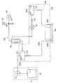
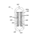
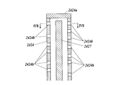
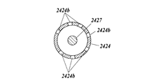
- FIG. 1 is a schematic diagram illustrating an overall configuration of an ink jet recording apparatus according to an embodiment. It is a figure explaining the flow path of an ink. It is a schematic sectional drawing of an external reflux type deaeration module. It is a schematic sectional drawing which shows the structure inside the center pipe
- the ink jet recording apparatus 1 of the present invention includes a paper feeding unit 10, an image forming unit 20, a paper discharge unit 30, a control unit 40, and an ink supply unit 50.
- the image forming unit 20 uses the ink supplied from the ink supply unit 50 to the recording medium P conveyed from the paper supply unit 10 to the image forming unit 20 based on the control of the control unit 40. After the image is formed, the recording medium P is discharged to the paper discharge unit 30.
- the paper feeding unit 10 holds the recording medium P on which image formation is performed and supplies the recording medium P to the image forming unit 20 before image formation.
- the paper feed unit 10 includes a paper feed tray 11 and a transport unit 12.
- the paper feed tray 11 is a plate-like member provided so that one or a plurality of recording media P can be placed thereon.
- the paper feed tray 11 is provided so as to move up and down according to the amount of the recording medium P placed thereon, and is held at a position where the uppermost recording medium P is transported by the transport unit 12.
- the transport unit 12 is mounted on the paper feed tray 11 and a transport mechanism that transports the recording medium P on the belt 123 by rotationally driving a ring-shaped belt 123 by a plurality of (for example, two) rollers 121 and 122.
- the recording medium P includes a supply unit that transfers the uppermost one to the belt 123.
- the transport unit 12 transports the recording medium P delivered to the belt 123 by the supply unit as the belt 123 rotates.
- the image forming unit 20 forms an image by ejecting ink onto the recording medium P.
- the image forming unit 20 includes an image forming drum 21, a delivery unit 22, a paper heating unit 23, a head unit 24, an irradiation unit 25, and a delivery unit 26.
- the image forming drum 21 carries the recording medium P along the cylindrical outer peripheral surface, and conveys the recording medium P as it rotates.
- the conveyance surface of the image forming drum 21 faces the paper heating unit 23, the head unit 24, and the irradiation unit 25, and performs processing related to image formation on the conveyed recording medium P.
- the delivery unit 22 is provided at a position between the transport unit 12 of the paper feed unit 10 and the image forming drum 21, and delivers the recording medium P transported by the transport unit 12 to the image forming drum 21.
- the delivery unit 22 is a swing arm unit 221 that supports one end of the recording medium P conveyed by the conveyance unit 12, and a cylindrical delivery drum that delivers the recording medium P carried on the swing arm unit 221 to the image forming drum 21.
- the recording medium P on the transport unit 12 is picked up by the swing arm unit 221 and transferred to the transfer drum 222 to guide the recording medium P in the direction along the outer peripheral surface of the image forming drum 21 to form an image. Delivered to drum 21.
- the paper heating unit 23 heats the recording medium P carried on the image forming drum 21.
- the sheet heating unit 23 includes, for example, an infrared heater and generates heat in response to energization.
- the sheet heating unit 23 is provided in the vicinity of the outer peripheral surface of the image forming drum 21 and on the upstream side of the head unit 24 in the conveyance direction of the recording medium P by the rotation of the image forming drum 21. Heat generation of the sheet heating unit 23 is controlled by the control unit 40 so that the recording medium P carried on the image forming drum 21 and passing through the vicinity of the sheet heating unit 23 has a predetermined temperature.
- the head unit 24 discharges ink to the recording medium P carried on the image forming drum 21 to form an image.
- the head unit 24 is individually provided for each color of C (cyan), M (magenta), Y (yellow), and K (black).
- head units 24 corresponding to the colors Y, M, C, and K are provided in order from the upstream with respect to the conveyance direction of the recording medium P that is conveyed along with the rotation of the image forming drum 21.
- the head unit 24 of the present embodiment is provided with a length (width) that covers the entire recording medium P in a direction (width direction) perpendicular to the conveyance direction of the recording medium P. That is, the ink jet recording apparatus 1 is a one-pass line head type ink jet recording apparatus.
- the head unit 24 can constitute a line head by arranging a plurality of recording heads 24a (see FIG. 2).
- the irradiation unit 25 irradiates an energy beam for curing the ink after the ink used in the ink jet recording apparatus 1 of the present embodiment is ejected onto the recording medium P.
- the irradiation unit 25 includes, for example, a fluorescent tube such as a low-pressure mercury lamp, and emits the fluorescent tube to emit energy rays such as ultraviolet rays.
- the irradiation unit 25 is provided in the vicinity of the outer peripheral surface of the image forming drum 21 and on the downstream side of the head unit 24 in the conveyance direction of the recording medium P by the rotation of the image forming drum 21.
- the irradiation unit 25 irradiates the recording medium P carried on the image forming drum 21 and ejects the ink with energy rays, and cures the ink ejected onto the recording medium P by the action of the energy rays.
- Fluorescent tubes emitting ultraviolet rays include low-pressure mercury lamps, mercury lamps having an operating pressure of several hundred Pa to 1 MPa, light sources usable as germicidal lamps, cold cathode tubes, ultraviolet laser light sources, metal halide lamps, light-emitting diodes, etc. Is mentioned.
- a light source for example, a light emitting diode
- the energy rays are not limited to ultraviolet rays, but may be any energy rays having a property of curing the ink according to the properties of the ink, and the light source is replaced according to the wavelength of the energy rays.
- the delivery unit 26 conveys the recording medium P irradiated with the energy rays from the irradiation unit 25 from the image forming drum 21 to the paper discharge unit 30.
- the delivery unit 26 rotates the annular belt 263 by a plurality of (for example, two) rollers 261 and 262 and conveys the recording medium P on the belt 263, and the recording medium P from the image forming drum 21.
- a cylindrical delivery drum 264 and the like are provided to the transport mechanism.
- the delivery unit 26 conveys the recording medium P transferred to the belt 263 by the transfer drum 264 by the belt 263 and sends it to the paper discharge unit 30.
- the paper discharge unit 30 stores the recording medium P sent out from the image forming unit 20 by the delivery unit 26.
- the paper discharge unit 30 includes a plate-shaped paper discharge tray 31 and the like, and the recording medium P after image formation is placed on the paper discharge tray 31.
- the ink supply unit 50 stores ink, supplies the ink to the head unit 24 of the image forming unit 20, and enables ink of each color to be ejected from the nozzles of the head unit 24.
- the ink used in the ink jet recording apparatus 1 of the present embodiment is not particularly limited, and is, for example, an ultraviolet (UV) curable ink.
- This UV curable ink undergoes a phase change between a gel state and a liquid (sol) state according to temperature in a state where UV is not irradiated.
- the ink has a predetermined temperature, for example, a phase change temperature of about 40 to 100 ° C., and is uniformly liquefied (solified) by being heated and raised above the phase change temperature.
- the ink gels below the predetermined temperature including the normal room temperature (0 to 30 ° C.).
- the ink pumped out from the ink tank 51 of the ink supply unit 50 by the supply pump 53 is supplied to each recording head 24a via the ink flow path 24b. Further, the ink that has not been ejected by each recording head 24a can be returned to the ink flow path 24b as necessary.
- a first sub tank 241, a degassing module 242, a liquid feed pump 243, a check valve 244, a second sub tank 245, and the like are provided on the ink flow path 24b.
- the recording head 24a and the ink flow path 24b are heated and kept warm by an ink heating unit 270 including a heater, a heat transfer member that transmits heat from the heater, and the temperature of the ink is maintained at an appropriate temperature. It is like that.
- the heater of the ink heating unit 270 for example, a heating wire is used, and when energized, Joule heat is generated.
- a member having high thermal conductivity for example, a heat conduction plate formed of various metals (alloys) is used, and covers the piping of the ink flow path 24b, or the first sub tank 241 and the second sub tank 245. It is provided in contact with the side wall of.
- the deaeration module 242 is an external reflux type deaeration module having a hollow fiber membrane 2426 inside as a gas permeable membrane that can permeate dissolved gas in a liquid.
- the deaeration module 242 also measures a vacuum pump 249 for reducing the atmospheric pressure in the deaeration module 242, a vacuum path 250 connecting the vacuum pump 249 and the deaeration module 242, and an atmospheric pressure in the vacuum path 250.
- a pressure sensor 251 that connects to the vacuum path 250 and an atmosphere release valve 252 that can switch between an airtight state and an atmosphere release state are connected.
- the deaeration module 242, the vacuum pump 249, the vacuum path 250, the pressure sensor 251, the atmosphere release valve 252, etc. constitute a deaeration device 280.
- the first sub tank 241 is an ink chamber having a smaller volume than the one or a plurality of ink tanks 51 for storing ink pumped from the ink tank 51 by the supply pump 53.
- the first sub tank 241 is provided with a first float sensor 241a, and the control unit 40 operates the supply pump 53 based on the liquid level position detection data by the first float sensor 241a to store a predetermined amount of ink. It has come to be.
- the deaeration module 242 will be described with reference to FIG. In the example shown in FIG. 3, an external reflux type deaeration module 242 is shown.
- the deaeration module 242 is formed in, for example, a cylindrical shape, removes (degass) dissolved gas in the ink that has flowed in, and discharges the degassed ink.
- the deaeration module 242 is configured to cover a large number of hollow fiber membranes (gas permeable membranes) 2426 around the central tube 2424 inside an outer shell (chamber) 2421.
- One end of the central tube 2424 is connected to the ink inlet 2422, and the other is sealed with a plug 2424a.
- An infinite number of fine holes (holes) 2424b are provided on the outer wall of the central tube 2424.
- the ink flowing from the ink inlets 2422 flows out of the fine holes 2424b to the surroundings, and the ink flow It flows out from the outlet 2423.
- the ink outlet 2423 is provided sideways so that the ink flows out to the side of the deaeration module 242.
- the present invention is not limited to this.
- 2423 may be provided in any direction, and may be configured such that ink flows out in any direction.
- the hollow fiber membrane 2426 has a number of hollow fine yarn structures with one end closed, and the membrane surface has gas permeability.
- the other end of the fine fiber structure of the hollow fiber membrane 2426 is connected to a gas outlet 2425 to which a vacuum path 250 is connected.
- a heating unit 2427 is provided inside the central tube 2424.
- 4A is a schematic cross-sectional view showing a configuration inside the central tube 2424
- FIG. 4B is a cross-sectional view taken along the line IVB-IVB in FIG. 4A.
- the heating unit 2427 has, for example, a heating wire and a thermocouple inside a bar member made of SUS.
- the heating unit 2427 is arranged at the center of the deaeration module 242, so that the ink in the deaeration module 242 can be heated uniformly and efficiently, and the ink can be reduced to a target temperature. Can be heated in time.
- the entire ink in the deaeration module 242 can be heated uniformly, it is possible to prevent a region where the ink is not locally heated from occurring in the corner of the deaeration module 242.
- the ink can be heated uniformly and efficiently, the deaeration efficiency of the ink and the liquid feeding amount can be improved, the viscosity of the ink can be sufficiently lowered, and the occurrence of non-ejection of the ink can be caused. Can be suppressed.
- the control of the temperature of the heating unit 2427 is performed by the control unit 40.
- the control unit 40 detects the temperature of the heating unit 2427 using a thermocouple built in the heating unit 2427, and performs on / off control using a value that is appropriately set according to the type of liquid as a target temperature.
- the shape and configuration of the heating unit 2427 may be any shape and configuration as long as the ink in the deaeration module 242 can be heated and the heating temperature can be controlled.
- the heating unit 2427 itself generates heat.
- the heating element itself is provided outside the degassing module 242, and the heat of the heating element is transferred to the heating unit 2427 so that the inside of the degassing module 242 is heated. There may be.
- a second heating unit 2428 for heating the liquid in the deaeration module 242 is provided on the outer surface of the deaeration module 242. That is, the second heating unit 2428 is formed in a planar shape and is provided so as to cover the outer peripheral surface of the outer shell 2421 of the deaeration module 242.
- a rubber heater or the like is used as the second heating unit 2428.
- the second heating unit 2428 is provided with a temperature sensor such as a thermistor (not shown), and on / off control is performed by the control unit 40 in the same manner as the heating unit 2427. By providing such a second heating unit 2428, the ink in the deaeration module can be heated to a target temperature in a shorter time.
- the vacuum pump 249 shown in FIG. 2 is a diaphragm pump that includes a pump chamber having an expandable diaphragm and a drive source that operates the diaphragm so that the volume of the pump chamber expands and contracts.
- the pump chamber is provided with a suction port provided with a check valve that allows only inflow of fluid from the outside, and a discharge port provided with a check valve that allows only discharge of fluid from the inside. .
- the pressure sensor 251 detects the atmospheric pressure in the vacuum path 250 and outputs the result to the control unit 40.
- the control unit 40 drives and controls the vacuum pump 249 based on the detection result from the pressure sensor 251.
- the atmosphere release valve 252 is an electromagnetic valve that can switch the vacuum path 250 between an airtight state and an atmosphere release state in accordance with an operation command from the control unit 40.
- the liquid feed pump 243 sends the ink flowing out from the ink outlet 2423 of the deaeration module 242 to the second sub tank 245.
- a check valve 244 is provided between the liquid feed pump 243 and the second sub tank 245 to prevent the ink once sent to the second sub tank 245 from flowing backward.
- the second sub tank 245 is a small ink chamber in which the ink deaerated by the deaeration module 242 is temporarily stored, and is not particularly limited, but has a capacity approximately the same as that of the first sub tank 241.
- the ink in the second sub tank 245 is connected to the inlet 240a of each recording head 24a, and ink corresponding to the amount of ink ejected from the nozzles is supplied to each recording head 24a.
- the second sub-tank 245 is provided with a second float sensor 245a, and the control unit 40 operates the liquid feed pump 243 based on the liquid level position detection data by the second float sensor 245a, thereby supplying a predetermined amount of ink. It is to be stored.
- the ink that has not been ejected from the nozzles of the recording head 24a can be returned from the outlet 240b to the first sub tank 241 via the recovery path 241b and the valve 241c.
- the ink in the recording head 24a can be collected without being discarded by opening the valve 241c.
- the control unit 40 controls the operation of each unit of the inkjet recording apparatus 1 and controls the entire operation.
- the control unit 40 includes a CPU (Central Processing Unit), a ROM (Read Only Memory), a RAM (Random Access Memory), and the like.
- various processing programs such as a system program stored in the ROM are read out and expanded in the RAM, and the program expanded in the RAM is executed by the CPU.
- Various control processes such as temperature control are performed.
- the degassing device 280 including the degassing module 242 that removes the dissolved gas in the liquid, heating for heating the liquid in the degassing module 242 at the center of the degassing module 242.
- the portion 2427 the liquid in the deaeration module 242 can be heated uniformly and efficiently, and the liquid in the deaeration module can be heated to a target temperature in a short time.
- the liquid in the deaeration module 242 can be heated to a target temperature in a shorter time. Can do.
- the deaeration module 242 is an external reflux type deaeration module having a hollow fiber membrane 2426 that can permeate dissolved gas in the liquid
- the heating unit 2427 heats the liquid with a simple apparatus configuration. And a large amount of liquid can be degassed.
- the deaeration module 242 leaks from the cylindrical outer shell 2421 and a plurality of fine holes 2424b provided on the peripheral surface of the outer shell 2421 provided at the center of the outer shell 2421 and flowing from one end side.
- a hollow fiber membrane 2426 that is provided around the central tube 2424 in the outer shell 2421 and degasses the liquid leaked from the central tube 2424, and a heating portion 2427 is formed in a rod shape. Since the liquid in the deaeration module 242 can be brought into direct contact with the heating unit 2427 by being provided inside the central tube 2424, the liquid in the deaeration module 242 can be heated more efficiently. .
- the deaeration module 80 includes a substantially cylindrical chamber 81, a rod-shaped heating unit 82 provided coaxially at the center of the chamber 81, and a hollow fiber member 83 provided spirally around the heating unit 82. , And is configured.
- a gas outlet 81 a connected to the vacuum path 250 is provided at the upper end surface of the chamber 81, and the inside of the chamber 81 is decompressed by being sucked by the vacuum pump 249.
- a heating source by radiant heat such as an infrared heater as the heating unit 82.
- the heating unit 82 is provided with a temperature sensor, and the surface temperature of the heating unit 82 is controlled by the control unit 40 based on the detection result of the temperature sensor.
- the hollow fiber member 83 has a structure in which a plurality of hollow fiber membranes are bundled, and has an ink inlet 83a at one end and an ink outlet 83b at the other end.
- the ink inlet 83 a and the ink outlet 83 b are provided on the upper end surface of the chamber 81.
- the size and number of the hollow fiber membranes constituting the hollow fiber member 83 are appropriately set according to the configuration of the deaeration device 280 or the inkjet recording device 1 or the liquid (ink) to be deaerated, For example, several hundreds of hollow fiber membranes having an inner diameter of 0.5 mm and a radial thickness of about 0.3 mm are bundled.
- the ink passes through the hollow fiber membranes of the hollow fiber member 83 and the pressure in the chamber 81 is reduced. Only the dissolved gas in the ink is selectively degassed through the membrane surface. The dissolved gas taken out through the membrane surface flows down the vacuum path 250 through the chamber 81.
- the internal reflux type deaeration module 80 is configured as described above.
- the deaeration device 280 is mounted on the ink jet recording apparatus 1, but may be mounted on a device other than the ink jet recording device, or the deaeration device alone. It is good also as what is used in.
- the deaeration device 280 is configured by the deaeration module 242, the vacuum pump 249, the vacuum path 250, the pressure sensor 251, the atmosphere release valve 252, and the like.
- the configuration of the air device is not limited to this, and may not include a pressure sensor, an air release valve, or the like, or may include another member.
- the deaeration module 242 is configured to have the hollow fiber membrane 2426 as a gas permeable membrane that can permeate dissolved gas in the liquid, but the configuration of the deaeration module 242 is not limited thereto.
- a module that degass the dissolved gas by ultrasonic waves, a module that gas-displaces the dissolved gas by He purge, or the like may be used.
- the deaeration module 242 is connected to the vacuum pump 249 via the vacuum path 250, but an ink trap for storing liquid components is provided in the vacuum pump 249 in the vacuum path 250. You may make it provide in the front
- the hollow fiber membrane 2426 of the deaeration module 242 may permeate not only the dissolved gas contained in the ink but also a very small amount of liquid component, and the liquid component may infiltrate into the vacuum path 250 in some cases. By providing the ink trap, the liquid component can be prevented from flowing into the vacuum pump 249 and the vacuum pump 249 can be protected.
- the present invention is suitable for providing a deaeration device capable of heating the liquid in the deaeration module to a target temperature in a short time and an ink jet recording apparatus including the same.
Landscapes
- Chemical & Material Sciences (AREA)
- Chemical Kinetics & Catalysis (AREA)
- Engineering & Computer Science (AREA)
- Water Supply & Treatment (AREA)
- Ink Jet (AREA)
Abstract
L'invention est un dispositif de désaération (280) équipé d'un module de désaération (242) pour retirer du gaz dissous dans un liquide, et se caractérise en ce qu'il comprend une unité de chauffage (2427) située au centre du module de désaération (242) pour chauffer le liquide présent à l'intérieur du module de désaération (242).
Priority Applications (1)
| Application Number | Priority Date | Filing Date | Title |
|---|---|---|---|
| JP2016527695A JP6436168B2 (ja) | 2014-06-12 | 2015-05-11 | 脱気装置及びインクジェット記録装置 |
Applications Claiming Priority (2)
| Application Number | Priority Date | Filing Date | Title |
|---|---|---|---|
| JP2014121139 | 2014-06-12 | ||
| JP2014-121139 | 2014-06-12 |
Publications (1)
| Publication Number | Publication Date |
|---|---|
| WO2015190200A1 true WO2015190200A1 (fr) | 2015-12-17 |
Family
ID=54833305
Family Applications (1)
| Application Number | Title | Priority Date | Filing Date |
|---|---|---|---|
| PCT/JP2015/063451 Ceased WO2015190200A1 (fr) | 2014-06-12 | 2015-05-11 | Dispositif de désaération et appareil d'impression par jet d'encre |
Country Status (2)
| Country | Link |
|---|---|
| JP (1) | JP6436168B2 (fr) |
| WO (1) | WO2015190200A1 (fr) |
Cited By (5)
| Publication number | Priority date | Publication date | Assignee | Title |
|---|---|---|---|---|
| US20190084314A1 (en) * | 2017-09-21 | 2019-03-21 | Konica Minolta Inc. | Deaerator and inkjet recording device |
| JP2021017029A (ja) * | 2019-07-23 | 2021-02-15 | コニカミノルタ株式会社 | 画像形成装置 |
| JP2022111532A (ja) * | 2021-01-20 | 2022-08-01 | コニカミノルタ株式会社 | 脱気モジュール及びインクジェット記録装置 |
| US20230182480A1 (en) * | 2021-12-13 | 2023-06-15 | Brother Kogyo Kabushiki Kaisha | Liquid supply system, control method, non-transitory computer-readable medium storing computer-readable instructions, and liquid supply device |
| US20230182479A1 (en) * | 2021-12-13 | 2023-06-15 | Brother Kogyo Kabushiki Kaisha | Liquid supply system, control method, non-transitory computer-readable medium storing computer-readable instructions, and liquid supply device |
Citations (5)
| Publication number | Priority date | Publication date | Assignee | Title |
|---|---|---|---|---|
| JPH08207312A (ja) * | 1994-10-31 | 1996-08-13 | Hewlett Packard Co <Hp> | インクジェットペンのための脱気機構 |
| JPH1148493A (ja) * | 1997-08-01 | 1999-02-23 | Seiko Epson Corp | インクジェット式記録装置 |
| JP2001299137A (ja) * | 2000-04-25 | 2001-10-30 | Matsushita Electric Works Ltd | 養殖装置 |
| JP2003341083A (ja) * | 2002-05-30 | 2003-12-03 | Canon Inc | インクジェット記録装置用の脱気装置及び脱気方法 |
| JP2011079295A (ja) * | 2009-09-11 | 2011-04-21 | Seiko I Infotech Inc | インクジェットプリンタ |
Family Cites Families (3)
| Publication number | Priority date | Publication date | Assignee | Title |
|---|---|---|---|---|
| US7360882B2 (en) * | 2005-04-22 | 2008-04-22 | Toshiba Tec Kabushiki Kaisha | Ink-jet recording apparatus, method of removing air of ink-jet recording apparatus and removing air device |
| JP2007130907A (ja) * | 2005-11-11 | 2007-05-31 | Sii Printek Inc | インクジェット記録装置およびインクの脱気方法 |
| US8205977B2 (en) * | 2005-11-30 | 2012-06-26 | Konica Minolta Holdings, Inc. | Degassing method of ink-jet ink, production method of ink-jet ink and ink-jet printer |
-
2015
- 2015-05-11 JP JP2016527695A patent/JP6436168B2/ja active Active
- 2015-05-11 WO PCT/JP2015/063451 patent/WO2015190200A1/fr not_active Ceased
Patent Citations (5)
| Publication number | Priority date | Publication date | Assignee | Title |
|---|---|---|---|---|
| JPH08207312A (ja) * | 1994-10-31 | 1996-08-13 | Hewlett Packard Co <Hp> | インクジェットペンのための脱気機構 |
| JPH1148493A (ja) * | 1997-08-01 | 1999-02-23 | Seiko Epson Corp | インクジェット式記録装置 |
| JP2001299137A (ja) * | 2000-04-25 | 2001-10-30 | Matsushita Electric Works Ltd | 養殖装置 |
| JP2003341083A (ja) * | 2002-05-30 | 2003-12-03 | Canon Inc | インクジェット記録装置用の脱気装置及び脱気方法 |
| JP2011079295A (ja) * | 2009-09-11 | 2011-04-21 | Seiko I Infotech Inc | インクジェットプリンタ |
Cited By (10)
| Publication number | Priority date | Publication date | Assignee | Title |
|---|---|---|---|---|
| US20190084314A1 (en) * | 2017-09-21 | 2019-03-21 | Konica Minolta Inc. | Deaerator and inkjet recording device |
| JP2019055530A (ja) * | 2017-09-21 | 2019-04-11 | コニカミノルタ株式会社 | 脱気装置およびインクジェット記録装置 |
| JP2021017029A (ja) * | 2019-07-23 | 2021-02-15 | コニカミノルタ株式会社 | 画像形成装置 |
| JP7354644B2 (ja) | 2019-07-23 | 2023-10-03 | コニカミノルタ株式会社 | 画像形成装置 |
| JP2022111532A (ja) * | 2021-01-20 | 2022-08-01 | コニカミノルタ株式会社 | 脱気モジュール及びインクジェット記録装置 |
| JP7631824B2 (ja) | 2021-01-20 | 2025-02-19 | コニカミノルタ株式会社 | 脱気モジュール及びインクジェット記録装置 |
| US20230182480A1 (en) * | 2021-12-13 | 2023-06-15 | Brother Kogyo Kabushiki Kaisha | Liquid supply system, control method, non-transitory computer-readable medium storing computer-readable instructions, and liquid supply device |
| US20230182479A1 (en) * | 2021-12-13 | 2023-06-15 | Brother Kogyo Kabushiki Kaisha | Liquid supply system, control method, non-transitory computer-readable medium storing computer-readable instructions, and liquid supply device |
| US12304219B2 (en) * | 2021-12-13 | 2025-05-20 | Brother Kogyo Kabushiki Kaisha | Liquid supply system, control method, non-transitory computer-readable medium storing computer-readable instructions, and liquid supply device |
| US12370805B2 (en) * | 2021-12-13 | 2025-07-29 | Brother Kogyo Kabushiki Kaisha | Liquid supply system, control method, non-transitory computer-readable medium storing computer-readable instructions, and liquid supply device |
Also Published As
| Publication number | Publication date |
|---|---|
| JP6436168B2 (ja) | 2018-12-12 |
| JPWO2015190200A1 (ja) | 2017-04-20 |
Similar Documents
| Publication | Publication Date | Title |
|---|---|---|
| JP6361727B2 (ja) | インクジェット記録装置 | |
| JP6477696B2 (ja) | インクジェット記録装置 | |
| JP6436168B2 (ja) | 脱気装置及びインクジェット記録装置 | |
| CN105209261B (zh) | 喷墨记录装置及记录头的维护方法 | |
| JP6187335B2 (ja) | インクジェット記録装置 | |
| JP6569683B2 (ja) | 圧力調整装置及びインクジェット記録装置 | |
| JP2019130511A (ja) | 脱気装置及びインクジェット記録装置 | |
| JP2006297902A (ja) | 脱気方法及び脱気装置並びにインクジェット記録装置 | |
| JP6620753B2 (ja) | インク加熱装置及びインクジェット記録装置 | |
| JP6584183B2 (ja) | 印刷システム、印刷装置、印刷方法、及びインク供給方法 | |
| WO2015125521A1 (fr) | Appareil d'impression à jet d'encre | |
| JP6962093B2 (ja) | インクジェット記録装置 | |
| JP6707261B2 (ja) | 印刷装置 | |
| JP6900711B2 (ja) | インクジェット記録装置及びインクジェット記録装置の制御方法 | |
| JP6708128B2 (ja) | インク供給装置、インクジェット記録装置及びインク供給方法 | |
| JP6822838B2 (ja) | インクジェット記録装置及びインクの温度制御方法 | |
| JPWO2016098536A1 (ja) | 脱気装置及びインクジェット記録装置 | |
| JP2007130907A (ja) | インクジェット記録装置およびインクの脱気方法 | |
| JP2007276393A (ja) | インクジェット記録装置 | |
| JP2026070569A (ja) | インクジェット記録システム | |
| JP2025092207A (ja) | 圧力調整装置、液滴吐出装置、圧力調整方法及びプログラム | |
| JP2024140396A (ja) | 脱気装置、液滴吐出装置、脱気方法及びプログラム | |
| JP2025120974A (ja) | インクジェット記録装置、モノマー貯留量推定方法及びプログラム | |
| JP2025080888A (ja) | 脱気装置、インクジェット記録装置、脱気方法及びプログラム |
Legal Events
| Date | Code | Title | Description |
|---|---|---|---|
| 121 | Ep: the epo has been informed by wipo that ep was designated in this application |
Ref document number: 15807246 Country of ref document: EP Kind code of ref document: A1 |
|
| ENP | Entry into the national phase |
Ref document number: 2016527695 Country of ref document: JP Kind code of ref document: A |
|
| NENP | Non-entry into the national phase |
Ref country code: DE |
|
| 122 | Ep: pct application non-entry in european phase |
Ref document number: 15807246 Country of ref document: EP Kind code of ref document: A1 |