WO2015190277A1 - Joint doté d'un dispositif pare-flammes - Google Patents
Joint doté d'un dispositif pare-flammes Download PDFInfo
- Publication number
- WO2015190277A1 WO2015190277A1 PCT/JP2015/064915 JP2015064915W WO2015190277A1 WO 2015190277 A1 WO2015190277 A1 WO 2015190277A1 JP 2015064915 W JP2015064915 W JP 2015064915W WO 2015190277 A1 WO2015190277 A1 WO 2015190277A1
- Authority
- WO
- WIPO (PCT)
- Prior art keywords
- fuel tank
- main body
- pipe
- fuel
- joint
- Prior art date
- Legal status (The legal status is an assumption and is not a legal conclusion. Google has not performed a legal analysis and makes no representation as to the accuracy of the status listed.)
- Ceased
Links
Images


Classifications
-
- B—PERFORMING OPERATIONS; TRANSPORTING
- B60—VEHICLES IN GENERAL
- B60K—ARRANGEMENT OR MOUNTING OF PROPULSION UNITS OR OF TRANSMISSIONS IN VEHICLES; ARRANGEMENT OR MOUNTING OF PLURAL DIVERSE PRIME-MOVERS IN VEHICLES; AUXILIARY DRIVES FOR VEHICLES; INSTRUMENTATION OR DASHBOARDS FOR VEHICLES; ARRANGEMENTS IN CONNECTION WITH COOLING, AIR INTAKE, GAS EXHAUST OR FUEL SUPPLY OF PROPULSION UNITS IN VEHICLES
- B60K15/00—Arrangement in connection with fuel supply of combustion engines or other fuel consuming energy converters, e.g. fuel cells; Mounting or construction of fuel tanks
- B60K15/03—Fuel tanks
- B60K15/035—Fuel tanks characterised by venting means
-
- F—MECHANICAL ENGINEERING; LIGHTING; HEATING; WEAPONS; BLASTING
- F02—COMBUSTION ENGINES; HOT-GAS OR COMBUSTION-PRODUCT ENGINE PLANTS
- F02M—SUPPLYING COMBUSTION ENGINES IN GENERAL WITH COMBUSTIBLE MIXTURES OR CONSTITUENTS THEREOF
- F02M37/00—Apparatus or systems for feeding liquid fuel from storage containers to carburettors or fuel-injection apparatus; Arrangements for purifying liquid fuel specially adapted for, or arranged on, internal-combustion engines
Definitions
- the present invention relates to a joint with a frame arrester that is connected to a tube connected to a fuel pipe extending from a fuel tank and prevents flame from propagating into the fuel tank.
- the fuel tank of an automobile is connected to an oil supply pipe for supplying fuel.
- an oil supply pipe for supplying fuel.
- air or fuel vapor remains in the fuel tank. Otherwise, the pressure in the fuel tank will increase, making it impossible to refuel.
- the fuel tank is configured so that air and fuel vapor are returned to the fuel filler opening side via a line connected to the fuel filler pipe, which is called a vent line or a breather line.
- Patent Document 1 describes a piping structure of a vehicle fuel tank provided with such a breather line.
- the breather line in this structure has a breather pipe having one end connected to the other end of the oil supply pipe, and a breather tube having one end connected to the other end of the breather pipe, The other end of the breather tube is attached to the tube attachment port, and the tube attachment port is fixed to the upper portion of the fuel tank, so that the breather tube is disposed between the fuel tank and the fuel supply pipe (see paragraphs 0031 and 0031). (See FIG. 1).
- a highly volatile material such as ethanol may be used.
- Such highly volatile fuel is easy to ignite, and the flame may propagate into the fuel tank through the vent line or breather line.
- flame arresters having flame retarding properties are installed in the middle of the vent lines and breather lines as described above.
- a fuel tank device for a fuel tank for a vehicle is provided (see FIG. 3), which is equipped with a mesh-shaped frame arrester that allows but prevents the passage of flame.
- Patent Document 2 since a flame arrester is installed in the depth of the oil supply port of the oil supply guide cylinder, it becomes a resistance at the time of oil supply. Therefore, the flame arrester as described above may be installed in the middle of the breather line as in the piping structure of Patent Document 1 described above.
- an object of the present invention is to provide a joint with a frame arrester that can reduce the number of parts, simplify the structure, and maintain the sealing performance of a vent line or the like.
- the joint with a flame arrester according to the present invention is disposed outside a fuel tank filled with highly volatile fuel and connected to a tube connected to a fuel pipe extending from the fuel tank. And preventing a flame generated by the fuel from propagating into the fuel tank, wherein a fluid passage is formed therein, and a connection portion connected to the tube is connected to one end of the fluid passage.
- a frame arrester having a flame-extinguishing filter portion disposed between the main body portion and the pipe portion with the pipe portion attached to the main body portion.
- the frame arrester includes the filter portion and an annular member that holds the peripheral portion
- An annular seal member is disposed on the outer periphery of the cylindrical portion, and the annular member of the frame arrester is disposed closer to the fuel tank than the position where the seal member is disposed, and the fuel tank of the pipe portion
- a small-diameter cylindrical part is formed on the side, and the pipe part is connected to the main body part via an enlarged-diameter part extending from the end of the small-diameter cylindrical part, the cylindrical part, A large-diameter cylindrical portion into which the seal member and the annular member are inserted is formed, and a gap between the cylindrical portion and the large-diameter cylindrical portion is sealed by the seal member, and toward the fuel tank side of the annular member Movement is restricted by the enlarged diameter part Is moving in the fuel tank side of the sealing member, characterized in that it is configured to be restricted by the enlarged
- the filter portion of the frame arrester is sandwiched between an end surface of the cylindrical portion of the main body portion and an enlarged diameter portion of the pipe portion.
- an engagement piece is formed on either the main body or the pipe, and the other of the main body or the pipe is engaged with the engagement piece.
- An engaging portion is formed, and when the cylindrical portion is inserted into the enlarged diameter cylindrical portion, the engaging piece engages with the engaging portion, and the pipe portion is attached to the main body portion. It is preferable that it is comprised so that it may be.
- the main body is fixed to the outer periphery of the opening of the fuel tank, and the tube connected to the fuel supply pipe is connected to the connecting portion of the main body so that the tube is attached to the fuel tank. Can be connected. Also, when the pipe part attached to the main body part is inserted into the fuel tank and the pressure in the fuel tank increases during fuel refueling etc., fuel vapor or the like is supplied to the fuel filler port side via the tube connected to the connection part. Can be returned. And since the flame arrester is attached between the main body and the pipe part, when the highly volatile fuel ignites and the flame enters, the flame is extinguished by the filter part provided in the flame arrester. Flames can be prevented from entering the tank.
- the frame arrester is built in the joint for connecting the tube connected to the oil supply pipe, multiple tubes and joints are unnecessary compared to the case where the frame arrester is installed in the middle of the tube.
- the number of parts can be reduced, the structure can be simplified, and the sealing performance of the vent line can be improved.
- the movement of the annular member on the fuel tank side with the pipe portion attached to the main body is regulated by the enlarged diameter portion, and the movement of the seal member to the fuel tank side is restricted to the enlarged diameter portion and / or Since it is regulated by the annular member, the seal member can be prevented from coming off with a simple structure.
- the joint 10 with the frame arrester (hereinafter simply referred to as “joint 10”) is disposed outside the fuel tank 1 filled with highly volatile fuel and extends from the fuel tank 1. It is connected to the tube 7 connected to the refueling pipe 5 and prevents the flame generated by the fuel from propagating into the fuel tank 1. Note that one end of the tube 7 is connected to the fuel tank 1 via the joint 10 and the other end of the tube 7 is connected to the fuel supply pipe 5 so that air or fuel vapor in the fuel tank is supplied during fueling.
- a vent line (also referred to as a breather line) is configured to flow out to the oil supply pipe 5 side (see FIGS. 1 and 4).
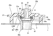
- the joint 10 in this embodiment is the state which the pipe part 40 was attached to the main-body part 20, the pipe part 40 attached to this main-body part 20, and the main-body part 20, as shown in FIG.1 and FIG.2.
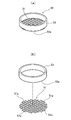
- the frame arrester 50 is disposed mainly between the main body portion 20 and the pipe portion 40 and has a flame extinguishing filter portion 51.
- the frame arrester 50 includes the filter portion 51 and an annular member 53 that holds the peripheral portion thereof.
- the filter unit 51 is made of, for example, a metal wire material such as stainless steel in a mesh shape, and allows the passage of gas such as fuel vapor or air while suppressing the propagation of flame. It is.
- the annular member 53 is made of, for example, a resin having high heat resistance such as polytetrafluoroethylene (PTFE) or polyether ether ketone (PEEK), general-purpose plastic, polyoxymethylene (POM), or the like. .
- the said filter part 51 in this embodiment is formed by punching the lattice-shaped mesh material which consists of the said metal wire material in circular shape, and the peripheral part has an annular
- a frame arrester 50 is formed by welding to one end surface 53a of the annular member 53 made.
- the frame arrester 50 may be formed by so-called insert molding in which the filter portion 51 is set in a mold and resin is injected to form the annular member 53.
- the filter unit 51 may have, for example, a circular shape, a rectangular shape, an elliptical shape, or the like, and the annular member 53 also has a corresponding annular shape, such as a rectangular shape or an elliptical shape.
- the filter unit 51 is not limited to a mesh shape, and may be, for example, a ribbon-like metal wire wound in a spiral shape with a predetermined gap, and absorbs and dissipates the heat of the flame. It suffices if flame propagation can be suppressed.
- the filter part 51 is formed by punching the mesh material into a circular shape, an end material 51a separated from the other metal wire material is generated at the peripheral part (see FIG. 3B). ).
- an end material 51a is welded to the annular member 53 as described above, and therefore can be prevented from falling off from the annular member 53, so that the inside of the fuel tank It can suppress becoming a contamination.
- the main body 20 has a fluid passage 21 formed therein, communicates with one end of the fluid passage 21, has a connection portion 23 connected to the tube 7, and is fixed to the outer periphery of the opening 3 of the fuel tank 1. It is what is done.
- the main body portion 20 of this embodiment includes a substantially hat-shaped base portion 25 that is formed with a fluid passage 21 extending in the vertical direction inside and closed upward, and a lower peripheral edge of the base portion 25. It has a fixing portion 27 that spreads in a flange shape and whose peripheral edge extends downward. Moreover, the tubular connection part 23 is extended from the upper side of the said base part 25 so that it may orthogonally cross, and the internal space is connected to the end of the said fluid channel
- peripheral edge of the opening of the fluid passage 21 on the fuel tank side that is, the peripheral edge of the opening on the lower side of the base 25 forms a cylindrical portion 29 extending toward the fuel tank side.
- annular seal member 60 is disposed on the outer periphery of the base end portion of the cylindrical portion 29, and the annular member 53 of the frame arrester 50 is attached to the outer periphery of the distal end portion of the cylindrical portion 29. It has come to be.
- An annular recess 31 is formed between the tubular portion 29 and the fixing portion 27, and the seal member 60 and the annular member 53 are disposed in the recess 31, and the seal member A large-diameter cylindrical portion 43 (described later) of the pipe portion 40 is inserted and disposed outside the 60 and the annular member 53.
- an insertion recess 31 a into which the tip of the large-diameter cylindrical portion 43 of the pipe portion 40 is inserted is formed above the recess 31.
- the lower end portion extending downward from the periphery of the fixing portion 27 is fixed to the outer peripheral edge of the opening 3 of the fuel tank 1 by means such as welding. Further, a plurality of engagement pieces 33 provided with engagement holes 33a are suspended from the inside of the fixing portion 27.
- the main body 20 is formed of a resin that can be welded to the resin fuel tank 1, such as an olefin resin such as polyethylene (PE) or polypropylene (PP).
- an olefin resin such as polyethylene (PE) or polypropylene (PP).
- the pipe portion 40 is attached to the main body portion 20 so as to extend into the fuel tank 1 and has a cylindrical shape communicating with the fluid passage 21.
- a small-diameter cylindrical portion 41 is formed on the pipe portion 40 on the fuel tank 1 side, and the small-diameter cylindrical portion is provided on the pipe portion 40 on the connection side to the main body portion 20. From the small-diameter cylindrical portion 41 into which the cylindrical portion 29 of the main body portion 20, the seal member 60, and the annular member 53 of the frame arrester 50 are inserted via the enlarged diameter portion 43 a that expands from the end portion of the 41. A large-diameter cylindrical portion 43 is also formed.
- a flange portion 45 is formed on the outer periphery of the large-diameter cylindrical portion 43 and is disposed on the back side of the fixing portion 27 of the main body portion 20.
- a plurality of gaps 45a are formed at predetermined positions of the flange portion 45, and a protrusion having a tapered outer surface at a position on the outer periphery of the pipe portion 40 and aligned with the plurality of gaps 45a.
- a projecting engagement portion 47 is projected. The engaging portion 47 is engaged with the engaging hole 33 a of the engaging piece 33 of the main body portion 20, so that the pipe portion 40 is attached to the main body portion 20.
- the flange portion 45 is arranged with a predetermined clearance C with respect to the back surface of the fixing portion 27 of the main body portion 20 (see FIG. 2). This corresponds to a dimensional error or the like with the engagement hole 33a or the engagement portion 47.
- the engagement piece 33 is provided on the main body 20 side and the engagement part 47 is provided on the pipe part 40 side.
- the engagement piece 33 is provided on the pipe part 40 side and the engagement part 47 is provided. You may provide in the main-body part 20 side.
- the engagement piece 33 has a shape having an engagement hole 33a.
- an engagement claw is provided at the tip of the engagement piece 33, and this is engaged with the protruding engagement portion 47. There is no particular limitation.
- the pipe part 40 has low rigidity and high rigidity due to fuel such as polyoxymethylene (POM), polyamide (PA) such as aliphatic polyamide and aromatic polyamide, and polybutylene terephthalate (PBT). It is made of resin.
- fuel such as polyoxymethylene (POM), polyamide (PA) such as aliphatic polyamide and aromatic polyamide, and polybutylene terephthalate (PBT). It is made of resin.
- the large-diameter cylindrical portion 43 is inserted and disposed in the concave portion 31 of the main body portion 20, and the distal end thereof is inserted into the insertion concave portion 31 a of the concave portion 31 and is disposed on the outer periphery of the proximal end portion of the cylindrical portion 29.
- the sealing member 60 In addition to being in contact with the sealing member 60, it is arranged on the outer periphery of an annular member 53 mounted on the outer periphery of the distal end portion of the cylindrical portion 29 (see FIG. 2).
- the gap between the cylindrical portion 29 and the large-diameter cylindrical portion 43 is sealed by the seal member 60, and the frame is interposed between the cylindrical portion 29 and the large-diameter cylindrical portion 43.
- the annular member 53 of the arrester 50 is sandwiched so that the movement of the annular member 53 toward the fuel tank 1 is restricted by the enlarged diameter portion 43a, and the movement of the seal member 60 toward the fuel tank 1 is It is regulated by the member 53.
- the end surface 29 a on the distal end side of the tubular portion 29 is in contact with the upper surface side of the filter portion 51 of the frame arrester 50, and the enlarged diameter portion of the large diameter tubular portion 43 is disposed on the lower surface side of the filter portion 51.
- 43a abuts (see FIG. 2), and the filter portion 51 is sandwiched between the end surface 29a on the distal end side of the tubular portion 29 and the enlarged diameter portion 43a of the large diameter tubular portion 43.
- the seal member 60 is disposed on the outer periphery of the base end portion of the cylindrical portion 29 of the main body portion 20, and the annular member 53 of the frame arrester 50 is mounted on the outer periphery of the distal end portion of the cylindrical portion 29.
- the plurality of engagement pieces 33 of the main body 20 are aligned with the plurality of gaps 45 a of the pipe 40, and the pipe 40 is pushed into the main body 20.
- the large-diameter cylindrical portion 43 of the pipe portion 40 is inserted into the concave portion 31 of the main body portion 20, and the tip thereof is inserted into the insertion concave portion 31 a of the concave portion 31, and a plurality of engaging pieces of the main body portion 20.
- 33 passes through the plurality of gaps 45a of the pipe portion 40, and the engagement holes 33a of the respective engagement pieces 33 engage with the engagement portions 47 of the pipe portion 40. Therefore, the pipe portion 40 is attached to the main body portion 20. Can be installed.
- the gap between the tubular portion 29 and the large-diameter tubular portion 43 is sealed by the seal member 60, and an annular shape is formed between the tubular portion 29 and the large-diameter tubular portion 43.
- the member 53 is sandwiched, and the end surface 29a of the cylindrical portion 29 is in contact with the upper surface side of the filter portion 51, and the enlarged diameter portion 43a of the large diameter cylindrical portion 43 is in contact with the lower surface side of the filter 51. Is sandwiched between the end surface 29 a of the cylindrical portion 29 and the enlarged diameter portion 43 a of the large diameter cylindrical portion 43.
- the pipe portion 40 is inserted into the opening 3 of the fuel tank 1, and the fixing portion 27 of the main body portion 20 is fixed to the outer peripheral edge of the opening 3 by hot plate welding or the like, whereby the joint 10 is attached to the fuel tank 1. Can be installed. Furthermore, one end of the tube 7 is connected to the outer periphery of the connection portion 23 of the main body 20 by connecting one end of the tube 7 connected by a connection tool (not shown) in the middle of the oil supply pipe 5 in the length direction. To the fuel tank 1.
- the pipe portion 40 is inserted and arranged in the fuel tank 1, so that fuel is supplied into the fuel tank 1 from the fuel filler port of the fuel pipe 5. Then, the air and fuel vapor remaining in the fuel tank 1 are returned to the fuel supply pipe 5 side through the pipe portion 40, the fluid passage 21 of the main body portion 20, the connection portion 23, and the tube 7, and outside the fuel tank. Therefore, the fuel can be supplied into the fuel tank 1. However, when the fuel level in the fuel tank 1 rises to a predetermined height and the tip opening of the pipe portion 40 is closed, air and fuel vapor in the fuel tank 1 are not discharged, so that the fuel is supplied to the fuel supply pipe.
- the inside of the fuel tank 1 can be raised and contacted with the sensor of the fueling nozzle to control the fueling into the fuel tank 1.
- the full tank regulation position in the fuel tank 1 can be appropriately adjusted according to the fuel tank to be applied. Can increase the sex.
- the seal member 60 and the annular member 53 of the frame arrester 50 are arranged on the outer periphery of the cylindrical portion 29 provided in the main body portion 20, and the outer periphery thereof. Is clamped by the enlarged diameter portion 43a of the large-diameter cylindrical portion 43 of the pipe portion 40, so that each member can be arranged coaxially with the joint 10 to achieve compactness and the tip of the cylindrical portion 29
- the annular member 53 disposed on the outer periphery of the side can prevent the sealing member 60 from coming off.
- the movement of the annular member 53 on the fuel tank 1 side in a state where the pipe part 40 is attached to the main body part 20 is regulated by the enlarged diameter portion 43a, and the movement of the seal member 60 to the fuel tank 1 side is Since it is regulated by the annular member 53, the seal member 60 can be prevented from coming off with a simple structure.
- the filter portion 51 of the frame arrester 50 includes the end surface 29 a of the tubular portion 29 of the main body portion 20 and the enlarged diameter portion 43 a of the large diameter tubular portion 43 of the pipe portion 40. Therefore, when the fuel tank 1 is refueled, when the air or fuel vapor passes through the filter unit 51, the filter unit 51 can be directly sandwiched between the filter unit 51 and the filter unit 51. The vibration of 51 can be suppressed.
- the main body 20 fixed to the outer periphery of the opening 3 of the fuel tank 1 is made of a resin (such as polyethylene described above) that can be thermally welded to the fuel tank 1, while the pipe portion 40 is Further, it can be made of a resin (such as polyoxymethylene (POM) described above) having excellent fuel impermeability and rigidity.
- a resin such as polyethylene described above
- POM polyoxymethylene
- the resin such as polyethylene that can be thermally welded to the fuel tank 1 constituting the main body 20 has fuel swellability, the diameter of the cylindrical portion 29 tends to increase. Since the large-diameter cylindrical portion 43 of the disposed pipe portion 40 is made of a resin having excellent fuel impermeability and low fuel swelling property, the frame arrester 50 can be firmly held. Moreover, when the sealing member 60 is arrange
- FIG. 5 shows another embodiment of the joint with a frame arrester according to the present invention. Note that substantially the same parts as those of the above-described embodiment are denoted by the same reference numerals, and description thereof is omitted.
- joint 10a (hereinafter simply referred to as “joint 10a”) of this embodiment includes a main body portion 20a, a pipe portion 40a, and a frame arrester 50a.
- the annular member 55 constituting the frame arrester 50a has a tapered shape in which the outer peripheral surface 55a is gradually reduced in diameter from one end to the other end in the thickness direction.
- cylindrical portion 30 of the main body portion 20a is formed shorter than the cylindrical portion 29 (see FIG. 2) of the above-described embodiment, and a seal member 60 is disposed on the outer periphery of the cylindrical portion 30.
- An annular member 55 of the frame arrester 50a is disposed on the fuel tank 1 side of the tubular portion 30 with respect to the position where the seal member 60 is disposed. In this embodiment, the annular member 55 is disposed so as to abut on the end surface 30 a of the tubular portion 30.
- the annular member 55 is arranged on the inner circumference of the enlarged diameter portion 48a of the pipe portion 40a, the cylindrical portion 30 on which the seal member 60 is arranged is inserted into the large diameter cylindrical portion 48, and is engaged with an engaging portion (not shown).
- the pipe part 40a can be attached to the main body part 20a by engaging the combined piece.
- the seal member 60 abuts on the outer periphery of the tubular portion 30 and also abuts on the inner peripheral surface of the enlarged diameter portion 48 a that constitutes the large diameter tubular portion 48. And the large-diameter cylindrical portion 48 are sealed by the seal member 60.
- the annular member 55 has an outer peripheral surface 55a in contact with an oblique inner peripheral surface of the enlarged diameter portion 48a, one end in contact with the end surface 30a of the cylindrical portion 30, and the cylindrical portion 30 and the enlarged diameter portion 48a.
- the movement of the annular member 55 on the fuel tank 1 side is regulated by the enlarged diameter portion 48a.
- the outer periphery of the seal member 60 is in contact with the enlarged diameter portion 48a, the one end surface is in contact with the annular member 55, and the movement toward the fuel tank side is 48a and the annular member 55 are regulated.
- the movement of the annular member 55 on the fuel tank 1 side in the state where the pipe portion 40a is attached to the main body portion 20a is restricted by the enlarged diameter portion 48a and the fuel of the seal member 60 Since the movement toward the tank 1 is restricted by the enlarged diameter portion 48a and the annular member 55, the seal member 60 can be prevented from coming off with a simple structure.
- FIG. 6 shows still another embodiment of the joint with the frame arrester according to the present invention. Note that substantially the same parts as those of the above-described embodiment are denoted by the same reference numerals, and description thereof is omitted.
- joint 10 b the joint with frame arrester 10 b (hereinafter simply referred to as “joint 10 b”) of this embodiment mainly differs in the shape of the pipe portion from the joint 10 a shown in FIG. 5.
- a large-diameter cylindrical portion 48 is formed at the end portion on the connection side to the main body portion 20a, and the large-diameter cylindrical portion 48 extends from the end portion of the small-diameter cylindrical portion 41 to the main body portion 20a.
- a diameter-expanding portion 48a that gradually expands and extends toward the end, and a tip portion 48b that extends from the tip in the extending direction of the diameter-expanding portion 48a with a constant diameter and is inserted into the insertion recess 31a of the recess 31 of the body portion 20a have.
- annular member 56 of the frame arrester 50a has a tapered outer peripheral surface 56a that contacts the inner peripheral surface of the enlarged diameter portion 48a, but does not contact the end surface 30a of the cylindrical portion 30. Yes.
- the seal member 60 When the pipe portion 40a is attached to the main body portion 20a, the seal member 60 is in contact with the outer periphery of the cylindrical portion 30, and is in contact with the inner peripheral surface of the distal end portion 48b of the large diameter cylindrical portion 48. The gap between the cylindrical portion 30 and the large diameter cylindrical portion 48 is sealed by the seal member 60.
- the outer peripheral surface 56a of the annular member 56 contacts the inner peripheral surface of the enlarged diameter portion 48a, and the movement of the annular member 56 on the fuel tank 1 side is restricted by the enlarged diameter portion 48a, and the seal member 60 is The movement of the seal member 60 toward the fuel tank in contact with the member 56 is regulated by the annular member 56.
- the movement of the annular member 56 on the fuel tank 1 side is restricted by the enlarged diameter portion 48a, and the movement of the seal member 60 toward the fuel tank side is caused by the enlarged diameter portion 48a and the annular member 56. Since it is regulated, the seal member 60 can be prevented from coming off with a simple structure.
- the large-diameter cylindrical portion 48 of the pipe portion 40a can also be formed in a compact manner, and the entire joint 10b can be formed in a compact manner.
Landscapes
- Engineering & Computer Science (AREA)
- Chemical & Material Sciences (AREA)
- Combustion & Propulsion (AREA)
- Mechanical Engineering (AREA)
- Life Sciences & Earth Sciences (AREA)
- Sustainable Development (AREA)
- Sustainable Energy (AREA)
- Transportation (AREA)
- General Engineering & Computer Science (AREA)
- Cooling, Air Intake And Gas Exhaust, And Fuel Tank Arrangements In Propulsion Units (AREA)
- Gasket Seals (AREA)
Abstract
Priority Applications (2)
| Application Number | Priority Date | Filing Date | Title |
|---|---|---|---|
| BR112016029005-4A BR112016029005B1 (pt) | 2014-06-10 | 2015-05-25 | Junta equipada com corta-chama |
| JP2016527727A JP6276855B2 (ja) | 2014-06-10 | 2015-05-25 | フレームアレスター付きジョイント |
Applications Claiming Priority (2)
| Application Number | Priority Date | Filing Date | Title |
|---|---|---|---|
| JP2014119542 | 2014-06-10 | ||
| JP2014-119542 | 2014-06-10 |
Publications (1)
| Publication Number | Publication Date |
|---|---|
| WO2015190277A1 true WO2015190277A1 (fr) | 2015-12-17 |
Family
ID=54833380
Family Applications (1)
| Application Number | Title | Priority Date | Filing Date |
|---|---|---|---|
| PCT/JP2015/064915 Ceased WO2015190277A1 (fr) | 2014-06-10 | 2015-05-25 | Joint doté d'un dispositif pare-flammes |
Country Status (3)
| Country | Link |
|---|---|
| JP (1) | JP6276855B2 (fr) |
| BR (1) | BR112016029005B1 (fr) |
| WO (1) | WO2015190277A1 (fr) |
Citations (3)
| Publication number | Priority date | Publication date | Assignee | Title |
|---|---|---|---|---|
| JPH0431020U (fr) * | 1990-07-06 | 1992-03-12 | ||
| JP2003301751A (ja) * | 2002-02-07 | 2003-10-24 | Kazuhiro Kawasaki | 燃料タンク及び燃料用パイプ |
| WO2007094419A1 (fr) * | 2006-02-15 | 2007-08-23 | Husqvarna Zenoah Co., Ltd. | Silencieux et machine de travail |
-
2015
- 2015-05-25 WO PCT/JP2015/064915 patent/WO2015190277A1/fr not_active Ceased
- 2015-05-25 BR BR112016029005-4A patent/BR112016029005B1/pt active IP Right Grant
- 2015-05-25 JP JP2016527727A patent/JP6276855B2/ja active Active
Patent Citations (3)
| Publication number | Priority date | Publication date | Assignee | Title |
|---|---|---|---|---|
| JPH0431020U (fr) * | 1990-07-06 | 1992-03-12 | ||
| JP2003301751A (ja) * | 2002-02-07 | 2003-10-24 | Kazuhiro Kawasaki | 燃料タンク及び燃料用パイプ |
| WO2007094419A1 (fr) * | 2006-02-15 | 2007-08-23 | Husqvarna Zenoah Co., Ltd. | Silencieux et machine de travail |
Also Published As
| Publication number | Publication date |
|---|---|
| BR112016029005A2 (pt) | 2017-08-22 |
| BR112016029005B1 (pt) | 2021-12-07 |
| JP6276855B2 (ja) | 2018-02-07 |
| JPWO2015190277A1 (ja) | 2017-04-20 |
Similar Documents
| Publication | Publication Date | Title |
|---|---|---|
| JP6200097B2 (ja) | 弁ケースの取付構造 | |
| KR20100093068A (ko) | 충전 노즐 위치설정 장치, 연료 충전 노즐 위치설정 장치 및 연료 충전 노즐 중심설정 장치 | |
| CN1765644B (zh) | 燃油箱上的虹吸式加油管与止回阀的组件 | |
| CN101549640A (zh) | 燃料加注装置 | |
| JP6841251B2 (ja) | 燃料バルブ | |
| US8596311B2 (en) | Valve assembly for a fuel recirculation line | |
| JP6173991B2 (ja) | 給油補助具 | |
| JP4924366B2 (ja) | 燃料給油装置 | |
| CN105612075A (zh) | 用于机动车工作流体容器的填充装置 | |
| JP2017524881A (ja) | 壁部用の通過装置 | |
| JP2013023168A (ja) | 燃料給油装置 | |
| JP6276855B2 (ja) | フレームアレスター付きジョイント | |
| EP2995491B1 (fr) | Structure de partie de ravitaillement d'un réservoir de carburant | |
| JP2008267348A (ja) | 燃料タンク | |
| JP6107575B2 (ja) | 燃料給油装置 | |
| WO2020255477A1 (fr) | Joint de tuyaux et ensemble joint de tuyaux | |
| CN102050014A (zh) | 汽车油箱加油管总成 | |
| JP6442301B2 (ja) | 自動車の金属製燃料タンクの給油管取付け構造 | |
| WO2018079206A1 (fr) | Dispositif de remplissage de carburant | |
| KR101707943B1 (ko) | 방폭용 플렉시블 조인트 장치 | |
| JP2008001253A (ja) | ベントチューブ | |
| KR101289980B1 (ko) | 역화방지 커플러 | |
| JP2015021466A (ja) | バルブ装置 | |
| JP2022093008A (ja) | 給油口 | |
| JP6107616B2 (ja) | 燃料給油装置 |
Legal Events
| Date | Code | Title | Description |
|---|---|---|---|
| 121 | Ep: the epo has been informed by wipo that ep was designated in this application |
Ref document number: 15807271 Country of ref document: EP Kind code of ref document: A1 |
|
| ENP | Entry into the national phase |
Ref document number: 2016527727 Country of ref document: JP Kind code of ref document: A |
|
| NENP | Non-entry into the national phase |
Ref country code: DE |
|
| REG | Reference to national code |
Ref country code: BR Ref legal event code: B01A Ref document number: 112016029005 Country of ref document: BR |
|
| 122 | Ep: pct application non-entry in european phase |
Ref document number: 15807271 Country of ref document: EP Kind code of ref document: A1 |
|
| ENP | Entry into the national phase |
Ref document number: 112016029005 Country of ref document: BR Kind code of ref document: A2 Effective date: 20161209 |