WO2015194285A1 - Appareil de traitement d'informations, procédé de traitement de données et dispositif terminal - Google Patents
Appareil de traitement d'informations, procédé de traitement de données et dispositif terminal Download PDFInfo
- Publication number
- WO2015194285A1 WO2015194285A1 PCT/JP2015/063553 JP2015063553W WO2015194285A1 WO 2015194285 A1 WO2015194285 A1 WO 2015194285A1 JP 2015063553 W JP2015063553 W JP 2015063553W WO 2015194285 A1 WO2015194285 A1 WO 2015194285A1
- Authority
- WO
- WIPO (PCT)
- Prior art keywords
- information processing
- streaming
- video
- processing apparatus
- user
- Prior art date
- Legal status (The legal status is an assumption and is not a legal conclusion. Google has not performed a legal analysis and makes no representation as to the accuracy of the status listed.)
- Ceased
Links
Images







Classifications
-
- H—ELECTRICITY
- H04—ELECTRIC COMMUNICATION TECHNIQUE
- H04N—PICTORIAL COMMUNICATION, e.g. TELEVISION
- H04N7/00—Television systems
- H04N7/14—Systems for two-way working
- H04N7/141—Systems for two-way working between two video terminals, e.g. videophone
- H04N7/147—Communication arrangements, e.g. identifying the communication as a video-communication, intermediate storage of the signals
-
- G—PHYSICS
- G06—COMPUTING OR CALCULATING; COUNTING
- G06V—IMAGE OR VIDEO RECOGNITION OR UNDERSTANDING
- G06V10/00—Arrangements for image or video recognition or understanding
- G06V10/20—Image preprocessing
- G06V10/22—Image preprocessing by selection of a specific region containing or referencing a pattern; Locating or processing of specific regions to guide the detection or recognition
- G06V10/225—Image preprocessing by selection of a specific region containing or referencing a pattern; Locating or processing of specific regions to guide the detection or recognition based on a marking or identifier characterising the area
-
- G—PHYSICS
- G06—COMPUTING OR CALCULATING; COUNTING
- G06V—IMAGE OR VIDEO RECOGNITION OR UNDERSTANDING
- G06V20/00—Scenes; Scene-specific elements
- G06V20/20—Scenes; Scene-specific elements in augmented reality scenes
-
- G—PHYSICS
- G06—COMPUTING OR CALCULATING; COUNTING
- G06V—IMAGE OR VIDEO RECOGNITION OR UNDERSTANDING
- G06V20/00—Scenes; Scene-specific elements
- G06V20/40—Scenes; Scene-specific elements in video content
- G06V20/41—Higher-level, semantic clustering, classification or understanding of video scenes, e.g. detection, labelling or Markovian modelling of sport events or news items
-
- H—ELECTRICITY
- H04—ELECTRIC COMMUNICATION TECHNIQUE
- H04N—PICTORIAL COMMUNICATION, e.g. TELEVISION
- H04N23/00—Cameras or camera modules comprising electronic image sensors; Control thereof
- H04N23/60—Control of cameras or camera modules
- H04N23/63—Control of cameras or camera modules by using electronic viewfinders
- H04N23/631—Graphical user interfaces [GUI] specially adapted for controlling image capture or setting capture parameters
-
- H—ELECTRICITY
- H04—ELECTRIC COMMUNICATION TECHNIQUE
- H04N—PICTORIAL COMMUNICATION, e.g. TELEVISION
- H04N23/00—Cameras or camera modules comprising electronic image sensors; Control thereof
- H04N23/60—Control of cameras or camera modules
- H04N23/63—Control of cameras or camera modules by using electronic viewfinders
- H04N23/633—Control of cameras or camera modules by using electronic viewfinders for displaying additional information relating to control or operation of the camera
-
- H—ELECTRICITY
- H04—ELECTRIC COMMUNICATION TECHNIQUE
- H04N—PICTORIAL COMMUNICATION, e.g. TELEVISION
- H04N23/00—Cameras or camera modules comprising electronic image sensors; Control thereof
- H04N23/60—Control of cameras or camera modules
- H04N23/66—Remote control of cameras or camera parts, e.g. by remote control devices
- H04N23/661—Transmitting camera control signals through networks, e.g. control via the Internet
Definitions
- the present disclosure relates to an information processing device, an information processing method, and a terminal device.
- a typical example of such a communication tool is a video conference system (see, for example, Patent Document 1 below).
- the system then streams the local environment video to the remote user's terminal device.
- Other examples of communication tools for remote communication are videophone and video chat.
- the local environment camera is often set by a local user and installed semi-fixed. If the remote user is approved to participate in the communication, the remote user can view the video in the local environment. However, the remote user cannot move in the local environment, and the view and behavior of the remote user in the local environment are greatly restricted by the system settings.
- the technology according to the present disclosure aims to reduce the above-described inconvenience of the remote user in remote communication and realize rich remote communication with a higher degree of freedom.
- the remote device is selected by the remote user from a communication unit that communicates between a camera that captures a real space, a communication device that communicates with a terminal device used by the remote user, and a plurality of devices that capture the real space
- a streaming control unit that streams the first video captured by the camera from the communication unit to the terminal device, and the remote user while the first video is streamed to the terminal device.
- an information processing apparatus including a display for displaying the user image.
- an information processing method executed by an information processing apparatus including a camera that captures a real space and a communication unit that communicates with a terminal device used by a remote user. Streaming the first video captured by the camera from the communication unit to the terminal device when the remote device is selected by the remote user from a plurality of devices that capture the real space; And displaying the user image of the remote user on a display while the video is streamed to the terminal device.
- the terminal device is a communication unit that communicates with a plurality of devices that respectively capture a real space, and a remote user who uses the terminal device among the plurality of devices is selected.
- a streaming control unit that plays back the first video that reflects the real space, and the user image of the remote user is selected while the first video is played back by the streaming control unit.
- a terminal device including a device control unit for displaying on a display of the device.
- an information processing method executed by a terminal device including a communication unit that communicates with a plurality of devices that respectively capture a real space, and the terminal device is selected from the plurality of devices. Playing a first video that reflects the real space, streamed from a device selected by a remote user to use, and selecting the user image of the remote user while the first video is being played
- An information processing method including displaying on a display of the device that has been selected.
- FIG. 2 is an explanatory diagram for describing an example of a local environment of the information processing system illustrated in FIG. 1. It is a block diagram which shows an example of a structure of the local device as an installation type device. It is a block diagram which shows an example of a structure of the local device as a portable device. It is a block diagram which shows an example of a structure of the local device as a mobile device. It is explanatory drawing which shows the additional example of a portable device. It is explanatory drawing which shows the additional example of a mobile device. It is explanatory drawing which shows the additional example of a mobile device.
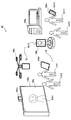
- FIG. 1 is an explanatory diagram for explaining an overview of an information processing system 1 according to an embodiment.
- the information processing system 1 includes local devices 100 a, 100 b, 100 c, 100 d, 100 e and 100 f existing in the local environment 10, a network 20, a remote terminal 200, and a management server 300.
- the local environment 10 may be an arbitrary environment in a real space where a real object may exist. Communication between users in the information processing system 1 is performed in the local environment 10.
- the local environment 10 may be installed in various places such as an office, a laboratory, a conference hall, a school, a shopping mall, an amusement park, or a home.
- the local devices 100a, 100b, 100c, 100d, 100e, and 100f are information processing apparatuses that exist in the local environment 10, respectively.
- the local device 100a is an electronic blackboard.
- the local device 100b is a desktop PC (Personal Computer).
- the local device 100c is a smartphone.
- the local device 100d is a tablet PC.
- the local device 100e is a quadcopter.
- the local device 100f is a talking head.
- Each local device 100 includes at least a camera and a communication interface. Each local device 100 has a function of photographing a real space using a camera and streaming the photographed real space video. Furthermore, each local device 100 may stream the sound collected through the microphone. Streaming data from each local device 100 can be delivered directly to the remote terminal 200 or can be relayed to the remote terminal 200 via the management server 300. Although FIG. 1 shows six local devices 100, the information processing system 1 may include fewer or more local devices 100 of any kind.
- the network 20 connects the local device 100, the remote terminal 200, and the management server 300 to each other.
- the network 20 may be any type of network, such as the Internet, a corporate network, a home network, or a personal network.
- the network 20 may be a wired network or a wireless network or a combination thereof.
- the network 20 may include one or more network devices (not shown) such as wireless access points, routers, switches, repeaters or bridges.
- the remote terminal 200 is a terminal device used by a remote user.
- the remote terminal 200 receives video data (and audio data) streamed on the network 20 from any local device 100 existing in the local environment 10 and reproduces video (and audio) in the real space of the local environment 10.
- the streaming source local device 100 is referred to as a streaming source device.
- the streaming source device is typically selected by the remote user.
- FIG. 1 shows only one remote terminal 200, the information processing system 1 may include more remote terminals 200.
- the management server 300 is an information processing apparatus that manages streaming between the local device 100 and the remote terminal 200 in the information processing system 1.
- the management server 300 includes, for example, a database that stores device data of each local device 100 (hereinafter referred to as local device data). Local device data may be provided to the remote terminal 200 to assist the remote user in device selection.
- the management server 300 may also have a database that stores user data of remote users (hereinafter referred to as remote user data). Note that the management server 300 may be omitted from the configuration of the information processing system 1. In that case, local device data and remote user data may be managed centrally by any local device 100 or remote terminal 200, or may be managed in a distributed manner by each device.
- a camera and a display are typically installed in a local environment.
- Camera and display settings can be made by a local user.
- These device settings are usually semi-fixed, although dynamic control such as panning, tilting and zooming may be allowed.
- Remote users cannot move within the local environment. Therefore, the field of view and behavior of the remote user in the local environment are greatly restricted by the settings of these devices.
- the plurality of local devices 100 described above are installed in the local environment 10.
- the remote user can access any of the freely selectable local devices 100 via the remote terminal 200, and can view the video from the selected local device 100, that is, the streaming source device.
- the selection of the streaming source device may be changed during the communication.
- a user image of the remote user for example, a photograph of the user or a character image that makes it possible to identify the remote user
- the local user recognizes which remote user is staying in which device (the remote user is viewing the video from which device) by viewing the user image displayed by the local device 100. Can do.
- the user image may be a moving image.
- the remote user's selection of the streaming source device is also notified to the local user through a symbolic animation displayed on the display.
- FIG. 2 is an explanatory diagram for describing an example of the local environment 10 of the information processing system 1 illustrated in FIG.
- a local device 100 a is installed in the local environment 10.
- the local device 100a includes a camera 101a and a display 105a.
- the local users LU11 and LU12 are gathered in front of the local device 100a.
- the user image of the remote user RU11 is displayed on the display 105a of the local device 100a.
- the remote user RU11 can talk with the local users LU11 and LU12 through the microphone and speaker (not shown) of the local device 100a.
- Local users LU13 and LU14 are gathered in front of the local device 100b.
- the local user LU 13 holds the local device 100c.
- the local device 100f has moved to the front of the local device 100b.
- a user image of the remote user RU12 is displayed on the display of the local device 100f.
- the user image of the remote user RU13 is displayed on the display of the local device 100c.
- Remote users RU12 and RU13 can talk to local users LU13 and LU14 through local devices 100f and 100c, respectively.
- the local device 100d is held by the local user LU11.
- the local device 100e is flying in front of the local device 100a. These local devices 100d and 100e can be photographed by the camera 101a of the local device 100a.
- the remote user RU11 recognizes the presence of the local devices 100d and 100e through video streamed from the local device 100a.
- the remote user RU11 selects the local device 100d as a new streaming source device.
- the remote user RU11 transfers to the local device 100d (actually, the remote user RU11 remains in a remote place, but the display of the user image of the remote user RU11 moves to the display of the local device 100d).
- the remote user RU 11 can virtually move within the local environment 10.
- the remote user RU11 selects the local device 100e as a new streaming source device. Then, the remote user RU11 changes to the local device 100e (actually, the remote user RU11 remains in a remote place, but the display of the user image of the remote user RU11 moves to the display of the local device 100e).
- the remote user RU11 remotely operates the local device 100e, the remote user RU11 can virtually move within the local environment 10.
- the remote user RU11 may participate in a conversation between the local users LU13 and LU14 and the remote users RU12 and RU13 after virtually moving in front of the local device 100b.
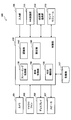
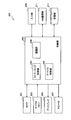
- FIG. 3A is a block diagram illustrating an example of the configuration of the local device 100 as an installed device.
- the local device 100 includes a camera 101, a microphone 103, a display 105, a speaker 107, an input unit 109, a network (NW) communication unit 111, a near field communication unit 113, a sensor module 115, a storage unit 117, and a control.
- the unit 120 is provided.
- the control unit 120 can function as the streaming control unit 130, the recognition unit 140, the display control unit 150, the setting unit 160, and the additional function unit 190.
- the stationary device is not limited to the example shown in FIGS. 1 and 2, and may be another type of device such as a television apparatus, a digital signage, or a navigation apparatus.
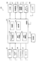
- FIG. 3B is a block diagram illustrating an example of the configuration of the local device 100 as a portable device.
- the local device 100 includes a battery 195 in addition to the blocks shown in FIG. 3A.
- the portable device is not limited to the examples shown in FIGS. 1 and 2, and may be another type of device such as a notebook PC, a PDA (Personal Digital Assistant), or a game terminal.
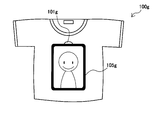
- FIG. 4A is an explanatory diagram illustrating an additional example of a portable device.
- the local device 100g is a T-shirt-like wearable device including a camera 101g and a display 105g. The local device 100g is worn by a local user and can move in the local environment with the local user.
- the local devices 100e and 100f are mobile devices that move according to an operation by a remote user or autonomously.
- FIG. 3C is a block diagram illustrating an example of a configuration of the local device 100 as a mobile device.
- the local device 100 includes a moving mechanism 119 in addition to the block group shown in FIG. 3B.
- the control unit 120 can additionally function as the movement control unit 170.
- the mobile device is not limited to the examples shown in FIGS. 1 and 2 and may be other types of devices.
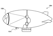
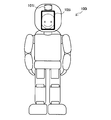
- 4B, 4C, and 4D are explanatory diagrams showing additional examples of the mobile device, respectively.
- the local device 100h is an airship including a camera 101h and a display 105h.
- the local device 100i is a humanoid robot including a camera 101i and a display 105i.
- the local device 100j is a pet robot including a camera 101j and a display 105j.
- the camera 101 has an image sensor such as a charge coupled device (CCD) or a complementary metal oxide semiconductor (CMOS), and takes an image. A series of images photographed by the camera 101 constitutes a video.
- the camera 101 outputs a video signal representing a captured video (typically, a video showing a real space of the local environment 10) to the control unit 120.
- the microphone 103 collects sound emitted in the vicinity of the local device 100 and generates a sound signal.
- the microphone 103 may be an omnidirectional microphone or may have directivity.
- the microphone 103 outputs the generated audio signal to the control unit 120.
- the display 105 includes a screen and a display circuit configured by an LCD (Liquid Crystal Display), an OLED (Organic light-Emitting Diode), a CRT (Cathode Ray Tube), and the like.
- the image is displayed under the control of.
- the display 105 may be a 3D display, a hologram display, a volume display, or the like instead of the 2D display that displays a two-dimensional image.
- the speaker 107 has circuit elements such as a diaphragm and an amplifier, and outputs sound based on an audio signal input from the control unit 120.
- the input unit 109 is an input interface used for a local user to operate the local device 100 or input information to the local device 100.
- the input unit 109 may include a touch sensor integrated with the display 105, for example.
- the input unit 109 may include other types of input interfaces such as buttons, switches, keyboards, pointing devices or keypads.
- the input unit 109 may include a voice recognition module that detects a user input based on a voice command, or a gesture recognition module that detects a user input based on a gesture command.
- the NW communication unit 111 is a communication interface that executes communication on the network 20.
- the NW communication unit 111 may be a wired communication interface that supports a wired communication protocol such as Ethernet. Instead, the NW communication unit 111 may be a wireless communication interface that supports a wireless communication protocol such as LTE (Long Term Evolution), WCDMA (Wideband Code Division Multiple Access), WiMAX, or wireless LAN (Local Area Network). Good.
- LTE Long Term Evolution
- WCDMA Wideband Code Division Multiple Access
- WiMAX Wireless LAN (Local Area Network). Good.
- the near field communication unit 113 is a near field communication interface that supports a near field communication protocol such as NFC (Near Field Communication), Bluetooth (registered trademark), TransferJet (registered trademark), or wireless USB. is there.
- the short-range communication unit 113 performs communication with a nearby device located in the vicinity of the local device 100 in the local environment 10.
- the sensor module 115 is a module that can include a sensor group such as a positioning sensor, an acceleration sensor, a gyro sensor, and a geomagnetic sensor.
- the positioning sensor measures the current position of the local device 100 based on, for example, a GPS signal from a GPS (Global Positioning System) satellite or a wireless signal from a wireless access point.
- the acceleration sensor measures triaxial acceleration applied to the local device 100.
- the gyro sensor measures the rotation of the local device 100.
- the geomagnetic sensor measures the geographical orientation of the local device.
- the storage unit 117 is configured by a storage medium such as a semiconductor memory or a hard disk, and stores a program and data for processing by the local device 100.
- the data stored by the storage unit 117 may include local device data of the local device 100, for example. Note that some of the programs and data described in this specification may be acquired from an external data source (for example, a data server, a network storage, or an external memory) without being stored in the storage unit 117. .
- the moving mechanism 119 is a moving unit that moves the local device 100 that is a mobile device in the real space under the control of the movement control unit 170 described later.
- the moving mechanism 119 may be a motor, a propeller (in the case of an aerial flight type such as a quadcopter or an airship), a wheel or a caterpillar (in the case of a ground movement type such as a talking head), or a walking actuator (such as a humanoid or pet robot).
- a walking type may be a motor, a propeller (in the case of an aerial flight type such as a quadcopter or an airship), a wheel or a caterpillar (in the case of a ground movement type such as a talking head), or a walking actuator (such as a humanoid or pet robot).
- a walking type may be a motor, a propeller (in the case of an aerial flight type such as a quadcopter or an airship), a wheel or a caterpillar (in the case of a ground movement type such
- the control unit 120 may be a processor such as a CPU (Central Processing Unit) or a DSP (Digital Signal Processor).
- the control unit 120 operates various functions of the local device 100 by executing a program stored in the storage unit 117 or another storage medium.
- the streaming control unit 130 displays a video of the local environment 10 captured by the camera 101 when the own apparatus is selected as a streaming source device by a remote user from a plurality of local devices that capture a real space. Streaming is performed from the NW communication unit 111 to the remote terminal 200.
- the streaming data streamed to the remote terminal 200 may include the sound of the local environment 10 collected by the microphone 103 in addition to the video of the local environment 10.
- the streaming control unit 130 may distribute the streaming data directly to the remote terminal 200 or may distribute the streaming data to the remote terminal 200 via the management server 300.
- the streaming control unit 130 starts video streaming to the remote terminal 200 in response to a streaming request received from the management server 300 via the NW communication unit 111, for example.
- the streaming request may be received when a remote user logs into the information processing system 1 and the local device 100 is selected as the initial streaming source device.
- the streaming request can also be received when the streaming source device is changed from a neighboring device in the real space to the own device.
- Video streaming to the remote terminal 200 can be continuously performed until an exit notification that means the exit of the remote user from the own device is received via the NW communication unit 111.
- the exit notification may be received, for example, when the remote user logs out from the information processing system 1 or when the streaming source device is changed to a nearby device in the real space.
- the recognizing unit 140 recognizes one or more neighboring devices in the local environment 10 that captures a real space video that can be streamed to the remote terminal 200.
- the recognition unit 140 may recognize a nearby device by detecting a marker displayed by the nearby device in an image captured by the camera 101.
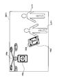
- FIG. 5 shows a state in which two local devices 100d and 100e are shown in the input image IM11 which is a frame constituting a video showing the local environment 10.
- the local device 100d displays a marker 142d.
- the local device 100e displays a marker 142e.
- the marker detected by the recognition unit 140 may be a known figure, symbol or character string, or a two-dimensional barcode.
- the markers may be displayed on the display 105 in a form that is not perceived by the local user using information hiding techniques (such as steganography).
- the device image of each local device 100 learned in advance may be used as a marker.
- the recognition unit 140 can identify a corresponding device based on the detected marker image, and can recognize the identified device as a neighboring device.
- the recognition unit 140 may recognize a nearby device based on device information received from the nearby device via the short-range communication unit 113.
- the recognition unit 140 of each local device 100 periodically broadcasts device information for causing the neighboring device to recognize that the local device 100 can stream real-space video from the short-range communication unit 113.
- the device information broadcast here may include, for example, the device ID of the local device 100 and other attribute information.
- the recognition unit 140 can recognize the device that is the transmission source of the received device information as a neighboring device.
- the recognizing unit 140 When the recognizing unit 140 recognizes a nearby device by any of the above-described methods (or other methods), the recognizing unit 140 notifies the remote terminal 200 of the presence of the recognized nearby device.
- the above-described exit notification can be received by the NW communication unit 111.
- Notification of neighboring devices to the remote terminal 200 may be performed indirectly via the management server 300.
- the management server 300 may notify the remote terminal 200 of the presence of a neighboring device capable of streaming video after verifying the compatibility of the streaming protocol between the recognized neighboring device and the remote terminal 200.
- the recognition of the neighboring device may be performed by the remote terminal 200 instead of the recognition unit 140 of the local device 100.
- the remote terminal 200 can recognize a nearby device of the local device 100 by detecting a marker that appears in a video streamed from the local device 100.
- the display control unit 150 causes the display 105 to display a user image of a remote user who views the video while the real space video is streamed to the remote terminal 200.
- the image data of the user image of the remote user may be included in the streaming request received by the NW communication unit 111, or may be acquired from the database using the user ID of the remote user. Further, the display control unit 150 may display user attributes such as a nickname of the remote user on the display 105 together with the user image.
- FIG. 6 is an explanatory diagram showing an example of display image transition in the local device 100 when the remote user changes to a nearby device (that is, the selected streaming source device is changed to a nearby device).
- the local device 100a is the streaming source device, and as shown on the left side of FIG. 6, the user image 152a of the remote user is displayed on the display 105a of the local device 100a.
- the remote user changes the streaming source device to the neighboring device 100e of the local device 100a.
- the display 105a displays an image 154a that forms an animation as if a remote user is popping out of the local device 100a.
- the local device 100a is no longer the streaming source device, and the marker 142a is displayed on the display 105a.
- FIG. 7 is an explanatory diagram illustrating an example of display image transition in the local device 100 when a remote user changes from a nearby device (that is, the selected streaming source device is changed to the own device).
- the local device 100e is a neighboring device for other devices that are streaming source devices.
- the marker 142e is displayed on the display 105e of the local device 100e. Thereafter, it is assumed that the remote user changes the streaming source device to the local device 100e.
- the display 105e displays an image 154e that forms an animation as if the remote user is about to enter the local device 100e.
- the local device 100e is the streaming source device, and the user image 152e of the remote user is displayed on the display 105e.
- the change of the streaming source device may be notified to other local devices 100 that are not involved in the change.
- the display control unit 150 of the local device 100 displays an animation in which the remote user changes between the two devices when at least one of the streaming source devices before or after the change is reflected in the input image. May be displayed.
- FIG. 8 is an explanatory diagram illustrating an example of a display image on the local device 100 that captures the two devices when the remote user is transferred between the two devices.
- the image IM12 shown in FIG. 8 shows the display 105a of the local device 100a and the display 105e of the local device 100e.
- the local device 100a is a streaming source device before change.
- the local device 100e is a changed streaming source device.
- the local user can see which device the remote user is staying in among the local devices 100 existing around him / her. It is possible to easily and intuitively recognize which device the user is browsing) and which device the remote user has transferred to.
- the display control unit 150 causes the display 105 to display the user image of the remote user who is staying at the own device.
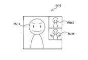
- the display control unit 150 is shown in FIG. 9 when there are a plurality of remote users staying in the own device, that is, when video is streamed to a plurality of remote terminals 200 respectively used by the plurality of remote users.
- the user images of the plurality of remote users may be displayed on the display 105.
- the display image IM13 displays user images of the remote users RU11, RU12, and RU14.
- the display control unit 150 can display the above-described marker on the display 105 when the remote user is not staying in the device itself or when the capacity for accepting a new remote user remains.
- the marker is used to make the neighboring device recognize that the device can stream the real space video. Note that when the device image of the appearance of the local device 100 is used as a marker, the display control unit 150 does not have to display the marker.
- the setting unit 160 sets the local device 100 in response to a user input from a local user existing in the real space. For example, the setting unit 160 measures the current position of the local device 100 based on the sensor data from the sensor module 115 and reports the positioning result to the management server 300. The setting unit 160 also sets whether to permit streaming of the video of the local environment 10 to the remote terminal 200 according to the user input detected via the input unit 109. When the streaming is not permitted, the streaming control unit 130 does not stream the video shot by the camera 101.
- the permission or non-permission of streaming may be set in any unit such as the address of the remote terminal 200, the user ID of the remote user, or the group to which the remote user belongs.
- one user may be allowed access to all local devices 100 while another user may be allowed only access to a particular type of local device 100 (eg, a stationary device). .
- a particular type of local device 100 eg, a stationary device.
- the movement control unit 170 is a functional block provided in the local device 100 when the local device 100 is a mobile device having the movement mechanism 119.
- the movement control unit 170 controls the movement mechanism 119 according to a movement control signal received from the remote terminal 200 during a period in which the remote user stays at the local device 100.
- the movement control signal may be, for example, a signal that instructs the local device 100 to move forward, backward, accelerate, decelerate, change direction, or (if possible) rise or fall.
- the movement control unit 170 may control the movement mechanism 119 autonomously according to some algorithm so that the local device moves in the local environment 10 during a period when the remote user is not staying at the local device 100. Good.
- the remote terminals 200 may compete with each other. For example, if two different remote users command the same local device 100 to move forward and backward simultaneously, the instructions compete with each other. In order to resolve such a conflict, the movement control unit 170 may determine the movement of the local device 100 based on a movement control signal received from at least one of the plurality of remote terminals 200 according to a predetermined condition.
- the predetermined condition here is to follow control by a master user among a plurality of remote users, to be based on a majority vote among a plurality of remote users, or to stop control when a conflicting control is instructed. To do.
- the user image of the remote user RU11 that is the master user is displayed larger than the user images of other remote users.
- the additional function unit 190 provides an additional function to the user depending on the capability of the local device 100.
- the additional functions provided by the additional function unit 190 may include, for example, a graphic drawing function (a function for displaying a graphic drawn by the remote user on the remote terminal 200 on the display 105). Further, the additional function may include a content reproduction function (a function for reproducing content on the local device 100 according to remote control from the remote terminal 200). Note that these functions are merely examples, and other functions may be provided by the additional function unit 190.
- the list of additional functions that can be provided by each local device 100 can be described in, for example, local device data.
- the local device 100 may include a battery 195.
- the battery 195 supplies operating power to each block in the figure through a power supply line partially shown by broken lines in FIGS. 3B and 3C.
- the local device 100 may transition to the power saving mode.
- the streaming control unit 130 may pause video streaming.
- the movement of the mobile device may be prohibited.
- FIG. 10 is a block diagram illustrating an example of the configuration of the remote terminal 200.
- the remote terminal 200 includes a camera 201, a microphone 203, a display 205, a speaker 207, an input unit 209, an NW communication unit 211, a storage unit 217, and a control unit 220.
- the control unit 220 can function as the streaming control unit 230, the recognition unit 240, and the device control unit 250.
- the camera 201 has an image sensor such as a CCD or a CMOS, and takes an image.
- An image captured by the camera 201 may include a user image of a remote user, for example.
- the camera 201 outputs an image signal representing the captured image to the control unit 220.
- the microphone 203 collects sound emitted by a remote user and generates a sound signal.
- the microphone 203 outputs the generated audio signal to the control unit 220.
- the display 205 includes a screen configured by an LCD, an OLED, or a CRT and a display circuit, and displays an image.
- the image displayed on the display 205 can include, for example, a GUI (Graphical User Interface) image described later.
- GUI Graphic User Interface
- the speaker 207 has circuit elements such as a diaphragm and an amplifier, and outputs sound based on an audio signal input from the control unit 220.
- the input unit 209 is an input interface used for a remote user to operate the remote terminal 200 or input information to the remote terminal 200.
- the input unit 209 may include a touch sensor integrated with the display 205, for example.
- the input unit 209 may include other types of input interfaces such as buttons, switches, keyboards, pointing devices, or keypads.
- the input unit 209 may include a voice recognition module that detects a user input based on a voice command, or a gesture recognition module that detects a user input based on a gesture command.
- the NW communication unit 211 is a communication interface that performs communication on the network 20.
- the NW communication unit 211 may be a wired communication interface that supports a wired communication protocol such as Ethernet. Instead, the NW communication unit 211 may be a wireless communication interface that supports a wireless communication protocol such as LTE, WCDMA, WiMAX, or wireless LAN.
- the NW communication unit 211 can communicate directly or via the management server 300 with the plurality of local devices 100 that respectively photograph real spaces.
- the storage unit 217 is configured by a storage medium such as a semiconductor memory or a hard disk, and stores programs and data for processing by the remote terminal 200.
- the data stored by the storage unit 217 may include remote user data of a remote user who uses the remote terminal 200, for example. Note that some of the programs and data described in this specification may be acquired from an external data source without being stored in the storage unit 217.
- the control unit 220 may be a processor such as a CPU or a DSP.
- the control unit 220 operates various functions of the remote terminal 200 by executing a program stored in the storage unit 217 or another storage medium.
- the streaming control unit 230 converts the streaming data distributed from the streaming source device that is one selected by the remote user from the plurality of local devices 100 existing in the local environment 10 to the NW communication unit 211. To receive. Then, the streaming control unit 230 reproduces the video included in the streaming data using the display 205. The video reproduced here is a video that reflects the real space of the local environment 10. Further, the streaming control unit 230 may reproduce the audio included in the streaming data using the speaker 207. Further, the streaming control unit 230 may perform streaming from the remote terminal 200 to the streaming source device. Streaming data streamed from the remote terminal 200 may include an image captured by the camera 201 and sound collected by the microphone 203. Streaming between the remote terminal 200 and the streaming source device may be performed directly or may be relayed by the management server 300.
- the recognizing unit 240 recognizes one or more neighboring devices of the streaming source device that are displayed in the video reproduced by the streaming control unit 230.
- the nearby device here is a local device 100 that can stream a real-space video from a different viewpoint from the video being played to the remote terminal 200.
- the recognition unit 240 may recognize the nearby device by detecting the above-described marker displayed by the nearby device in the reproduced video.
- the recognition unit 240 can identify a corresponding device based on the detected marker image, and can recognize the identified device as a neighboring device. Then, the recognition unit 240 notifies the device control unit 250 described later of the presence of the recognized neighboring device.
- recognition of neighboring devices may be performed exclusively by the recognition unit 140 of the local device 100. In that case, the recognition unit 240 can be omitted from the configuration of the remote terminal 200.
- the device control unit 250 presents information on the local device 100 in the local environment 10 that captures video that can be streamed to the remote terminal 200 to the remote user, and causes the remote user to select the streaming source device.
- the streaming source device when the remote user logs in to the information processing system 1 may be selected every time the remote user logs in, or may be a preset device set in advance.
- the device control unit 250 causes the streaming control unit 230 to play the video received from the selected streaming source device. Further, the device control unit 250 displays the user image of the remote user on the display of the streaming source device while the video from the streaming source device is being reproduced by the streaming control unit 230.
- the device control unit 250 moves the streaming source device to any neighboring device. Ask the remote user if it should be changed.
- the inquiry to the remote user may be performed via a GUI displayed on the display 205 or may be performed via sound output from the speaker 207.
- the device control unit 250 inquires of the user whether to change the streaming source device, the device control unit 250 may present information regarding the functionality of the recognized neighboring device to the remote user.
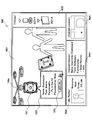
- FIG. 11 is an explanatory diagram showing an example of a GUI that can be displayed on the remote terminal 200.
- a GUI image IM2 that can be generated by the device control unit 250 is shown.
- the GUI image IM2 includes a streaming window W21, a profile window W22, a device information window W23, a location window W24, and a history window W25.
- the streaming window W21 displays a video that is played back by the streaming control unit 230.
- the local device 100e is shown in the video received from the streaming source device.
- the profile window W22 displays the remote user's profile.
- FIG. 11 is an explanatory diagram showing an example of a GUI that can be displayed on the remote terminal 200.
- the device information window W23 displays information regarding the streaming source device selected at that time.
- the name (Name), type (Type), and functionality (Functionality) of the local device 100a are displayed in the device information window W23.
- Such information can be provided from the management server 300 (or from the streaming source device) to the remote terminal 200, for example.
- the location window W24 displays a map indicating the current position in the local environment 10 of the selected streaming source device.
- the history window W25 displays a history of selection of a streaming source device, that is, a list of streaming source devices selected in the past.
- Display objects D21 and D22 are superimposed on the streaming window W21 in FIG.
- the display object D21 points to the marker of the local device 100e detected in the streamed video.
- the local device 100e is a neighboring device of the streaming source device.
- the display object D22 is an information area for displaying device information of the local device 100e recognized as a nearby device.
- the name, type, and functionality of the local device 100e are displayed by the display object D22.
- the display object D22 can also indicate information on a user staying at the local device 100e. However, in the example of FIG. 11, there is no user staying at the local device 100e (“None”).
- the display object D22 includes a button D23. The remote user can select the local device 100e as a new streaming source device by pressing (clicking or tapping) the button D23 via the input unit 209.
- the device control unit 250 transmits a device change request to the management server 300, for example.
- the management server 300 transmits a streaming request to the local device 100 selected as the new streaming source device, and notifies the streaming source device at that time of the exit notification. Can be sent. Instead, the device control unit 250 may directly transmit the streaming request and the exit notification to the local device 100 that is the destination. Note that, when the device displayed in the history window W25 is designated by the remote user, the device control unit 250 may change the streaming source device to the designated device.
- the device control unit 250 moves the streaming source device in response to a user input from a remote user while the video from the streaming source device is being played back.
- a movement control signal for controlling the movement may be generated.
- the movement control signal may be, for example, a signal instructing the streaming source device to move forward, backward, accelerate, decelerate, change direction, or ascend or descend (if possible).
- the movement control signal generated by the device control unit 250 can be transmitted to the streaming source device on the network 20 via the NW communication unit 211. For example, after a remote user transfers to a mobile device, the mobile device is moved to a place where communication between local users is performed (the movement here is not virtual) and participates in the communication. can do.
- the remote user can also move to the other local device 100 after moving the mobile device to the vicinity of the other local device 100.
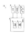
- FIG. 12 is a block diagram illustrating an example of the configuration of the management server 300.
- the management server 300 includes an input unit 309, an NW communication unit 311, a storage unit 317, and a control unit 320.
- the control unit 320 can function as the data management unit 330 and the connection management unit 340.
- the input unit 309 is an input interface used for an operator to operate the management server 300 or input information to the management server 300.
- the input unit 309 may include any type of input interface such as a touch sensor, a button, a switch, a keyboard, a pointing device, or a keypad.
- the NW communication unit 311 is a communication interface that performs communication on the network 20.
- the NW communication unit 311 may be a wired communication interface or a wireless communication interface.
- the NW communication unit 311 can communicate with the plurality of local devices 100 and the remote terminal 200 described above.
- the storage unit 317 is configured by a storage medium such as a semiconductor memory or a hard disk, and stores a program and data for processing by the management server 300.
- the data stored by the storage unit 317 can include, for example, local device data 350 and remote user data 360 described later.
- the control unit 320 may be a processor such as a CPU or a DSP.
- the control unit 320 operates various functions of the management server 300 by executing a program stored in the storage unit 317 or another storage medium.
- the data management unit 330 has a role as a manager that manages data stored in the storage unit 317. For example, when a new local device 100 is deployed in the local environment 10, the data management unit 330 adds a record corresponding to the device to the local device data 350. Further, when a new remote user is registered, the data management unit 330 adds a record corresponding to the user to the remote user data 360. In addition, the data management unit 330 maintains the contents of these data in the latest state through the exchange of messages between the local device 100 and the remote terminal 200.
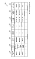
- FIG. 13 is an explanatory diagram showing an example of the configuration of the local device data 350 managed by the management server 300.
- the local device data 350 includes, as data items, a device ID 351, a name 352, a type 353, a functionality 354, an address 355, a position 356, an access restriction 357, and a status 358.
- the device ID 351 is an identifier that uniquely identifies each device.
- a name 352 represents a name given to each device.
- Type 353 represents the device type of each device. As a non-limiting example, the device type may be one of three types: a stationary type (“Stationary”), a portable type (“Portable”), and a mobile type (“Mobile”).
- the functionality 354 is a data item that describes a list of additional functions that can be provided by each device.
- the address 355 represents a destination address (for example, an IP address or a MAC address) to be inserted into a message transmitted to each device.
- a position 356 represents coordinates indicating the current position of each device.
- the data management unit 330 may update the corresponding position coordinates based on the positioning result report periodically received from each device.
- the access restriction 357 describes access restriction information for managing the remote user's access to each device. In the example of FIG. 13, access to the device having the device ID “DEV_A” or “DEV_C” is permitted to all users (“All Users”).
- a status 358 represents an operation status of each device.
- the data management unit 330 provides the remote terminal 200 with a subset of the local device data 350 described above.
- a subset of the streaming source device is displayed as device information.
- a subset of neighboring devices is displayed as device information.
- FIG. 14 is an explanatory diagram showing an example of the configuration of the remote user data 360 managed by the management server 300.
- the remote user data 360 includes a user ID 361, a nickname 362, a stay device 363, a terminal ID 364, a terminal address 365, and a user image 366 as data items.
- the user ID 361 is an identifier that uniquely identifies each remote user.
- the nickname 362 represents a nickname given to each remote user.
- the staying device 363 represents the device ID of the streaming source device that is currently selected by each remote user.
- the data management unit 330 can update the staying device 363 each time a remote user changes from one device to another.
- the terminal ID 364 is an identifier that identifies the remote terminal 200 used by each remote user.
- the terminal address 365 represents the address (for example, IP address or MAC address) of the remote terminal 200 used by each remote user.
- the user image 366 is a data item for storing image data of the user image of each remote user.
- connection management unit 340 manages the connection between the local device 100 and the remote terminal 200. For example, the connection management unit 340 accepts a login request from the remote terminal 200 and approves the login request when the remote user is successfully authenticated.
- the remote user authentication may be simple authentication based on an ID and password, or an IP address of a terminal, or may be more advanced authentication based on an encryption key or the like.
- the connection management unit 340 determines an initial device to be the first streaming source device of the remote user who has approved the login, and transmits a streaming request to the determined initial device.
- the streaming request may include remote user data for a remote user viewing the video being streamed.
- the initial device may be one specific local device 100 in the local environment 10 or may be a local device 100 that is predefined for each remote user. Alternatively, the remote user may select the initial device.
- the connection management unit 340 sends the streaming request to the new streaming in response to the device change request that can be received from the remote terminal 200. Send to original device.
- the connection management unit 340 may verify the compatibility of the protocol between the neighboring device and the remote terminal 200 before coordinating a new connection. Further, the connection management unit 340 may verify whether access from the remote terminal 200 to the neighboring device is permitted based on the access restriction information about the neighboring device.
- the connection management unit 340 can transmit an exit notification to the streaming source device before the change.
- connection management unit 340 transmits the local device data of the streaming source device that has approved the request to the remote terminal 200. Thereafter, streaming of video (and audio) from the streaming source device to the remote terminal 200 is started. In addition, the user image of the remote user is displayed on the streaming source device.
- the connection management unit 340 may relay the streaming data transmitted from the streaming source device to the streaming destination remote terminal 200.
- FIG. 15 is a sequence diagram illustrating an example of a flow of information processing when a remote user logs in to the system.
- the remote terminal 200 transmits a login request to the management server 300 (step S5).
- the management server 300 authenticates the remote user (step S10) and returns an authentication result to the remote terminal 200 (step S15).
- the remote terminal 200 transmits user data to the management server 300 (step S20).
- the user data transmitted here may include the latest information about the remote user (for example, a user image of the remote user taken at the time of login).
- the management server 300 determines an initial device among the plurality of local devices 100 existing in the local environment 10 for the remote user who has approved the login (step S25). Then, the management server 300 transmits a streaming request to the determined initial device (step S30). The local device 100 determined as the initial device returns a response indicating whether streaming is possible to the management server 300 (step S35). Here, it is assumed that the local device 100 determines that streaming is possible (for example, based on the capacity of the device). When receiving a response indicating that the streaming request has been accepted, the management server 300 transmits device information (a subset of the local device data 350) regarding the streaming source device to the remote terminal 200 (step S40).
- the local device 100 returns a response to the streaming request to the management server 300, and then displays the user image of the remote user on the display (step S50).
- the remote terminal 200 displays the device information provided from the management server 300 on the display (step S60).
- the management server 300 updates the data stored in the database (step S65). Thereafter, streaming of video (and audio) between the local device 100 and the remote terminal 200 is started (step S70).
- FIG. 16 is a sequence diagram illustrating an example of a flow of information processing when a remote user transfers from a local device to a nearby device. It is assumed that the local device 100a is selected as the streaming source device at the beginning of the sequence in FIG. The local device 100e is a neighboring device located in the vicinity of the local device 100a.
- step S100 video (and audio) streaming is executed between the local device 100a and the remote terminal 200 (step S100).
- the local device 100a or the remote terminal 200 recognizes a nearby device of the local device 100a (steps S105a and S105b).
- the recognition result of the neighboring device is reported to the management server 300.
- the management server 300 verifies the possibility of connection with the remote terminal 200 (for example, whether the protocol is compatible or whether access is permitted) for the recognized neighboring device (step S110).
- the local device 100e is recognized as a neighboring device, and the connection possibility between the local device 100e and the remote terminal 200 is affirmed.
- the management server 300 transmits device information about the verified neighboring device, that is, the local device 100e, to the remote terminal 200 (step S115).
- the remote terminal 200 displays the device information received from the management server 300 on the display, and asks the user whether to change to the local device 100e (that is, to change the streaming source device to the local device 100e) (step S120).
- the remote terminal 200 transmits a device change request to the management server 300 (step S130) when a user input instructing to change the streaming source device is detected (step S125).
- the management server 300 transmits a streaming request to the local device 100e (step S140).
- the local device 100e returns a response indicating whether streaming is possible to the management server 300 (step S145).
- the management server 300 further transmits an exit notification to the local device 100a (step S150).
- the local device 100a returns a confirmation response (ACK) to the exit notification to the management server 300 (step S155).
- ACK confirmation response
- the management server 300 returns a response indicating that the device change is permitted to the remote terminal 200 (step S160).
- the local device 100e that has accepted the streaming request displays an animation in which the remote user is transferred to the device as illustrated in FIG. 7 (step S165).
- the local device 100a that has received the exit notification displays an animation such as illustrated in FIG. 6 in which the remote user changes from the own device to the neighboring device.
- An animation in which a remote user moves to a nearby device may be further displayed on the remote terminal 200 (step S170).
- the local device 100e displays the user image of the remote user on the display after the above-described animation display is completed (step S175).
- the local device 100a deletes the user image of the remote user from the display (step S176).
- the remote terminal 200 displays the device information of the local device 100e provided from the management server 300 on the display (step S180).
- the management server 300 updates the data stored in the database (step S185). Thereafter, streaming of video (and audio) between the local device 100e and the remote terminal 200 is started (step S190). On the other hand, streaming between the local device 100a and the remote terminal 200 is stopped.
- a plurality of local devices that photograph the real space are arranged in the real space of the local environment.
- the local device selected by the remote user among the plurality of local devices causes the video captured by the camera of the device to be streamed to the remote terminal used by the remote user, and while the streaming is performed,
- the user image of the remote user is displayed on the display of the device. Therefore, the remote user can view the state of the local environment from the viewpoint of a desired device among various local devices existing in the local environment.
- the local user in the local environment can recognize from which viewpoint the remote user is viewing the state of the local environment by viewing the user image displayed on the local device.
- the remote user can flexibly move the viewpoint from one local device to another local device, and face-to-face communication between the remote user and the local user becomes possible.
- some local devices are realized as mobile devices having a mobile mechanism.
- the movement mechanism of the mobile device is controlled in accordance with a movement control signal received from the remote terminal. Therefore, by selecting a mobile device as the streaming source device, the remote user can control the mobile device while browsing the video streamed from the mobile device, and freely move the video viewpoint within the local environment. Can be made. For example, the remote user can move the mobile device to a place where a desired communication partner exists (for example, a conference room) and perform remote communication with the local user at that place.
- a desired communication partner for example, a conference room
- the presence of a nearby device in the vicinity of the local device that is streaming video to the remote terminal is recognized by the remote terminal or notified from the local device to the remote terminal. Therefore, the remote user can change the streaming source device in a chain manner from the local device currently selected to the neighboring device of the local device. By repeating such selection changes, a unique user experience is provided as if the remote user's ghost is moving freely from one device to another in the local environment.
- the display on the local device may display an animation that the remote user moves from device to device as the streaming source device changes. Accordingly, the local user can easily and intuitively recognize the movement of the remote user's viewpoint. Therefore, it is possible to prevent a local user's psychological burden that may be caused by difficulty in understanding where the remote user is viewing from.
- the remote terminal when a nearby device is recognized, the remote terminal provides a GUI for inquiring the remote user whether to change the streaming source device to the nearby device.
- the remote user can easily select the streaming source device via the GUI.
- the GUI provided by the remote terminal may present information regarding the functionality of neighboring devices to the remote user.
- the remote user can select a device having desired functionality as the streaming source device. For example, the remote user can change to the mobile device, search for the desired device by moving the video viewpoint within the local environment, and further transfer from the mobile device to the found desired device.
- a series of control processing by each device described in this specification may be realized using any of software, hardware, and a combination of software and hardware.
- the program constituting the software is stored in advance in a storage medium (non-transitory medium) provided inside or outside each device.
- Each program is read into a RAM (Random Access Memory) at the time of execution and executed by a processor such as a CPU.
- processing described using the sequence diagram in the present specification may not necessarily be executed in the order described. Some processing steps may be performed in parallel. Further, additional processing steps may be employed, and some processing steps may be omitted.
- a camera that shoots real space A communication unit that communicates with a terminal device used by a remote user; A streaming control unit configured to stream a first video captured by the camera from the communication unit to the terminal device when the remote device is selected by the remote user from a plurality of devices that capture the real space; A display for displaying a user image of the remote user while the first video is streamed to the terminal device;
- An information processing apparatus comprising: (2) The information processing apparatus includes: A moving mechanism for moving the information processing apparatus in the real space; A movement control unit for controlling the movement mechanism according to a movement control signal received from the terminal device; The information processing apparatus according to (1), further including: (3) The information processing apparatus includes: A recognition unit for recognizing a first neighboring device in the real space for capturing a second video that can be streamed to the terminal device; Further comprising The recognizing unit notifies the terminal device of the presence of the first neighboring device when the first neighboring device is recognized; The information processing apparatus according to (1) or (2)
- the information processing apparatus (4) The information processing apparatus according to (3), wherein the recognition unit recognizes the first neighboring device by detecting a marker displayed by the first neighboring device in the first video.
- the information processing apparatus includes a short-range communication unit, The recognizing unit recognizes the first neighboring device based on information received from the first neighboring device via the short-range communication unit; The information processing apparatus according to (3).
- the display displays an animation in which the remote user changes to the first neighboring device when a streaming source device for video streaming to the terminal device is changed from the information processing apparatus to the first neighboring device.
- the information processing apparatus according to any one of (3) to (5).
- the streaming control unit sends the first video to the terminal device when a streaming source device of video streaming to the terminal device is changed from a second neighboring device in the real space to the information processing device.
- the information processing apparatus according to any one of (1) to (6), wherein streaming is performed.
- the information processing apparatus includes: A display control unit for causing the display to display a marker indicating that the information processing apparatus is capable of streaming the first video;
- the information processing apparatus includes: A short-range communication unit that transmits information indicating that the information processing apparatus is capable of streaming the first video;
- the display is configured such that when the streaming source device for video streaming to the terminal device is changed from the second neighboring device to the information processing device, the remote user moves from the second neighboring device to the information processing device.
- the information processing apparatus according to any one of (7) to (9), wherein an animation for transferring is displayed.
- the information processing apparatus includes: A setting unit configured to set whether to permit streaming of the first video to the terminal device in response to a user input from a local user existing in the real space;
- the information processing apparatus according to any one of (1) to (10), further including: (12)
- the movement control unit is received from at least one of the plurality of terminal devices according to a predetermined condition when the first video is streamed to a plurality of terminal devices respectively used by a plurality of remote users.
- An information processing method executed by an information processing apparatus including a camera that captures a real space and a communication unit that communicates with a terminal device used by a remote user, Streaming the first video captured by the camera from the communication unit to the terminal device when the remote device is selected by the remote user from a plurality of devices that capture the real space; Displaying the user image of the remote user on a display while the first video is being streamed to the terminal device;
- An information processing method including: (14) A terminal device, A communication unit that communicates with a plurality of devices that photograph each real space; A streaming control unit that plays back the first video that reflects the real space and is streamed from a device selected by a remote user using the terminal device among the plurality of devices; A device controller that displays a user image of the remote user on the display of the selected device while the first video is being played by the streaming controller;
- a terminal device comprising: (15) When the first neighboring device in the real space that captures the second video that can be streamed to the terminal device is recognized
- the terminal device in which the user is inquired whether to change to the first neighboring device.
- the device control unit presents information regarding the functionality of the first neighboring device to the remote user when inquiring of the user whether the streaming source device should be changed to the first neighboring device, (15 ) Terminal device.
- the terminal device A recognition unit for recognizing the first neighboring device shown in the first video;
- the plurality of devices include at least one mobile device having a mobile mechanism;
- the device control unit sends the mobile device to the mobile device in order to control the movement of the mobile device according to a user input from the remote user.
- An information processing method executed by a terminal device including a communication unit that communicates with a plurality of devices that respectively photograph a real space, Replaying a first image reflecting the real space that is streamed from a device selected by a remote user using the terminal device among the plurality of devices; Displaying the user image of the remote user on the display of the selected device while the first video is being played back;
- DESCRIPTION OF SYMBOLS 1 Information processing system 10 Local environment 20 Network 100 Information processing apparatus (local device) DESCRIPTION OF SYMBOLS 101 Camera 105 Display 111 Network (NW) communication part 113 Near field communication part 119 Movement mechanism 130 Streaming control part 140 Recognition part 150 Display control part 160 Setting part 170 Movement control part 200 Terminal device (remote terminal) 211 Network (NW) communication unit 230 Streaming control unit 240 Recognition unit 250 Device control unit 300 Management server
Landscapes
- Engineering & Computer Science (AREA)
- Multimedia (AREA)
- Signal Processing (AREA)
- Physics & Mathematics (AREA)
- General Physics & Mathematics (AREA)
- Theoretical Computer Science (AREA)
- Human Computer Interaction (AREA)
- Computational Linguistics (AREA)
- Software Systems (AREA)
- Information Transfer Between Computers (AREA)
- Two-Way Televisions, Distribution Of Moving Picture Or The Like (AREA)
- User Interface Of Digital Computer (AREA)
Abstract
Le problème décrit par l'invention est de réduire les désagréments pour les utilisateurs distants utilisant une communication à distance, ce qui permet une communication à distance riche avec un degré élevé de liberté. La solution de la présente invention concerne un appareil de traitement d'informations qui comporte les élément suivants : une caméra qui réalise une image d'espace réel; une unité de communication qui communique avec un dispositif terminal utilisé par un utilisateur distant; une unité de commande de transmission en continu qui, si l'utilisateur à distance a sélectionné l'appareil de traitement d'informations parmi une pluralité de dispositifs qui réalisent une image de l'espace réel, diffuse en continu une première vidéo prise par la caméra depuis l'unité de communication vers le dispositif terminal; et un dispositif d'affichage qui affiche une image utilisateur associée à l'utilisateur à distance, tandis que la première vidéo susmentionnée est diffusée en continu au dispositif terminal.
Priority Applications (2)
| Application Number | Priority Date | Filing Date | Title |
|---|---|---|---|
| US15/314,504 US9894317B2 (en) | 2014-06-16 | 2015-05-12 | Controlling communication between a local device and a remote terminal device |
| US15/861,745 US10477143B2 (en) | 2014-06-16 | 2018-01-04 | Information processing device, information processing method, and terminal device |
Applications Claiming Priority (2)
| Application Number | Priority Date | Filing Date | Title |
|---|---|---|---|
| JP2014-123564 | 2014-06-16 | ||
| JP2014123564A JP2016005083A (ja) | 2014-06-16 | 2014-06-16 | 情報処理装置、情報処理方法及び端末装置 |
Related Child Applications (2)
| Application Number | Title | Priority Date | Filing Date |
|---|---|---|---|
| US15/314,504 A-371-Of-International US9894317B2 (en) | 2014-06-16 | 2015-05-12 | Controlling communication between a local device and a remote terminal device |
| US15/861,745 Continuation US10477143B2 (en) | 2014-06-16 | 2018-01-04 | Information processing device, information processing method, and terminal device |
Publications (1)
| Publication Number | Publication Date |
|---|---|
| WO2015194285A1 true WO2015194285A1 (fr) | 2015-12-23 |
Family
ID=54935279
Family Applications (1)
| Application Number | Title | Priority Date | Filing Date |
|---|---|---|---|
| PCT/JP2015/063553 Ceased WO2015194285A1 (fr) | 2014-06-16 | 2015-05-12 | Appareil de traitement d'informations, procédé de traitement de données et dispositif terminal |
Country Status (3)
| Country | Link |
|---|---|
| US (2) | US9894317B2 (fr) |
| JP (1) | JP2016005083A (fr) |
| WO (1) | WO2015194285A1 (fr) |
Families Citing this family (10)
| Publication number | Priority date | Publication date | Assignee | Title |
|---|---|---|---|---|
| JP2016005083A (ja) * | 2014-06-16 | 2016-01-12 | ソニー株式会社 | 情報処理装置、情報処理方法及び端末装置 |
| US10432894B2 (en) | 2016-03-23 | 2019-10-01 | Optim Corporation | Communication system, communication method, and program |
| JP6572831B2 (ja) * | 2016-06-14 | 2019-09-11 | 株式会社デンソー | 家電機器制御システム |
| JP6685851B2 (ja) * | 2016-06-17 | 2020-04-22 | オリンパス株式会社 | 撮像装置、操作装置、及び撮像システム |
| CN109451238A (zh) * | 2017-11-23 | 2019-03-08 | 北京臻迪科技股份有限公司 | 一种通信方法、通信系统及无人机 |
| CA3127756A1 (fr) | 2019-02-10 | 2020-08-13 | Myzeppi Ltd. | Dispositif de teleconference |
| US11202035B2 (en) | 2020-04-24 | 2021-12-14 | Facebook, Inc. | Dynamically modifying live video streams for participant devices in digital video rooms |
| JP7680000B2 (ja) * | 2020-12-08 | 2025-05-20 | Revisio株式会社 | 制御プログラム、制御装置および制御方法、ならびに、視聴質出力プログラム、視聴質出力装置および視聴質出力方法 |
| EP4117280A1 (fr) * | 2021-07-08 | 2023-01-11 | DG Inception GmbH | Dispositifs, systèmes et procédés de communication de téléprésence |
| WO2023053446A1 (fr) * | 2021-10-01 | 2023-04-06 | avatarin株式会社 | Système de communication et robot |
Citations (5)
| Publication number | Priority date | Publication date | Assignee | Title |
|---|---|---|---|---|
| WO2008106088A2 (fr) * | 2007-02-27 | 2008-09-04 | Roy Sandberg | Procédé et système pour faciliter des transactions commerciales en utilisant un robot de téléprésence |
| JP2011528570A (ja) * | 2008-07-11 | 2011-11-24 | インタッチ・テクノロジーズ・インコーポレーテッド | マルチキャスト機能を有するテレプレゼンス・ロボット・システム |
| US20120239196A1 (en) * | 2011-03-15 | 2012-09-20 | Microsoft Corporation | Natural Human to Robot Remote Control |
| US20120281092A1 (en) * | 2011-05-02 | 2012-11-08 | Microsoft Corporation | Visual communication using a robotic device |
| WO2013019402A1 (fr) * | 2011-08-02 | 2013-02-07 | Microsoft Corporation | Recherche d'un abonné appelé |
Family Cites Families (6)
| Publication number | Priority date | Publication date | Assignee | Title |
|---|---|---|---|---|
| JP2008306327A (ja) | 2007-06-06 | 2008-12-18 | Sony Corp | テレビ会議装置 |
| US8463435B2 (en) * | 2008-11-25 | 2013-06-11 | Intouch Technologies, Inc. | Server connectivity control for tele-presence robot |
| US8502856B2 (en) * | 2010-04-07 | 2013-08-06 | Apple Inc. | In conference display adjustments |
| US8581956B2 (en) * | 2011-04-29 | 2013-11-12 | Hewlett-Packard Development Company, L.P. | Methods and systems for communicating focus of attention in a video conference |
| US20130208123A1 (en) * | 2012-02-13 | 2013-08-15 | Honeywell International Inc. | Method and System for Collecting Evidence in a Security System |
| JP2016005083A (ja) * | 2014-06-16 | 2016-01-12 | ソニー株式会社 | 情報処理装置、情報処理方法及び端末装置 |
-
2014
- 2014-06-16 JP JP2014123564A patent/JP2016005083A/ja active Pending
-
2015
- 2015-05-12 US US15/314,504 patent/US9894317B2/en not_active Expired - Fee Related
- 2015-05-12 WO PCT/JP2015/063553 patent/WO2015194285A1/fr not_active Ceased
-
2018
- 2018-01-04 US US15/861,745 patent/US10477143B2/en not_active Expired - Fee Related
Patent Citations (5)
| Publication number | Priority date | Publication date | Assignee | Title |
|---|---|---|---|---|
| WO2008106088A2 (fr) * | 2007-02-27 | 2008-09-04 | Roy Sandberg | Procédé et système pour faciliter des transactions commerciales en utilisant un robot de téléprésence |
| JP2011528570A (ja) * | 2008-07-11 | 2011-11-24 | インタッチ・テクノロジーズ・インコーポレーテッド | マルチキャスト機能を有するテレプレゼンス・ロボット・システム |
| US20120239196A1 (en) * | 2011-03-15 | 2012-09-20 | Microsoft Corporation | Natural Human to Robot Remote Control |
| US20120281092A1 (en) * | 2011-05-02 | 2012-11-08 | Microsoft Corporation | Visual communication using a robotic device |
| WO2013019402A1 (fr) * | 2011-08-02 | 2013-02-07 | Microsoft Corporation | Recherche d'un abonné appelé |
Also Published As
| Publication number | Publication date |
|---|---|
| US9894317B2 (en) | 2018-02-13 |
| US20170201715A1 (en) | 2017-07-13 |
| JP2016005083A (ja) | 2016-01-12 |
| US10477143B2 (en) | 2019-11-12 |
| US20180131901A1 (en) | 2018-05-10 |
Similar Documents
| Publication | Publication Date | Title |
|---|---|---|
| WO2015194285A1 (fr) | Appareil de traitement d'informations, procédé de traitement de données et dispositif terminal | |
| US10504288B2 (en) | Systems and methods for shared creation of augmented reality | |
| US10917445B2 (en) | Communication sessions between computing devices using dynamically customizable interaction environments | |
| JP6096998B2 (ja) | インスタントメッセージング方法、装置、プログラム及び記録媒体 | |
| US11394757B2 (en) | Communication terminal, communication system, and method of sharing data | |
| US11416202B2 (en) | Communication terminal, communication system, method of sharing data, and recording medium | |
| US12483795B2 (en) | Communication terminal, display method, and non-transitory computer-readable medium for displaying videos captured by telepresence robot | |
| JP2017068329A (ja) | 通信管理システム、通信システム、通信管理方法、及びプログラム | |
| KR20140137736A (ko) | 그룹 메시지 표시 방법 및 장치 | |
| JP2017142610A (ja) | サーバ装置、伝送システム及びプログラム | |
| CN117221641A (zh) | 虚拟互动方法、装置、设备和存储介质 | |
| JP7806049B2 (ja) | 仮想位置を指示する実世界ビーコン | |
| WO2015129550A1 (fr) | Système de commande de transfert, système de transfert, procédé de commande de transfert et support d'enregistrement | |
| US12477040B2 (en) | Systems, methods, and media for controlling shared extended reality presentations | |
| JP2019135567A (ja) | 情報処理装置、管理システム、画像共有システム、画像共有方法およびプログラム | |
| JP2021039616A (ja) | 情報処理システム、情報処理装置、画像表示方法、プログラム | |
| JP6597299B2 (ja) | 共有端末、通信システム、通信方法、及びプログラム | |
| US20170111409A1 (en) | Transmission terminal, automatic response method, and recording medium | |
| CN116248942A (zh) | 互动处理方法、装置、电子设备及存储介质 | |
| JP6607034B2 (ja) | 共有端末、通信システム、通信方法、及びプログラム | |
| US20230308705A1 (en) | Communication terminal, communication management system, remote operation method, processing method, and communication management method | |
| JP2024126918A (ja) | 通信管理システム、通信システム、通信管理方法、及びプログラム | |
| JP2016195389A (ja) | 通信管理システム、通信システム、通信管理方法、及びプログラム | |
| JP2024079570A (ja) | 表示端末、通信システム、情報処理システム、表示方法、情報処理方法、通信方法、及びプログラム | |
| JP6812645B2 (ja) | 通信端末、通信システム、通信方法、及びプログラム |
Legal Events
| Date | Code | Title | Description |
|---|---|---|---|
| 121 | Ep: the epo has been informed by wipo that ep was designated in this application |
Ref document number: 15809227 Country of ref document: EP Kind code of ref document: A1 |
|
| WWE | Wipo information: entry into national phase |
Ref document number: 15314504 Country of ref document: US |
|
| NENP | Non-entry into the national phase |
Ref country code: DE |
|
| 122 | Ep: pct application non-entry in european phase |
Ref document number: 15809227 Country of ref document: EP Kind code of ref document: A1 |