WO2015194577A1 - Système de gestion de camion malaxeur, serveur de gestion de camion malaxeur, camion malaxeur et procédé de gestion de camion malaxeur - Google Patents
Système de gestion de camion malaxeur, serveur de gestion de camion malaxeur, camion malaxeur et procédé de gestion de camion malaxeur Download PDFInfo
- Publication number
- WO2015194577A1 WO2015194577A1 PCT/JP2015/067393 JP2015067393W WO2015194577A1 WO 2015194577 A1 WO2015194577 A1 WO 2015194577A1 JP 2015067393 W JP2015067393 W JP 2015067393W WO 2015194577 A1 WO2015194577 A1 WO 2015194577A1
- Authority
- WO
- WIPO (PCT)
- Prior art keywords
- mixer
- information
- server
- rotation
- rotation speed
- Prior art date
- Legal status (The legal status is an assumption and is not a legal conclusion. Google has not performed a legal analysis and makes no representation as to the accuracy of the status listed.)
- Ceased
Links
Images



Classifications
-
- B—PERFORMING OPERATIONS; TRANSPORTING
- B28—WORKING CEMENT, CLAY, OR STONE
- B28C—PREPARING CLAY; PRODUCING MIXTURES CONTAINING CLAY OR CEMENTITIOUS MATERIAL, e.g. PLASTER
- B28C5/00—Apparatus or methods for producing mixtures of cement with other substances, e.g. slurries, mortars, porous or fibrous compositions
- B28C5/42—Apparatus specially adapted for being mounted on vehicles with provision for mixing during transport
-
- B—PERFORMING OPERATIONS; TRANSPORTING
- B60—VEHICLES IN GENERAL
- B60K—ARRANGEMENT OR MOUNTING OF PROPULSION UNITS OR OF TRANSMISSIONS IN VEHICLES; ARRANGEMENT OR MOUNTING OF PLURAL DIVERSE PRIME-MOVERS IN VEHICLES; AUXILIARY DRIVES FOR VEHICLES; INSTRUMENTATION OR DASHBOARDS FOR VEHICLES; ARRANGEMENTS IN CONNECTION WITH COOLING, AIR INTAKE, GAS EXHAUST OR FUEL SUPPLY OF PROPULSION UNITS IN VEHICLES
- B60K17/00—Arrangement or mounting of transmissions in vehicles
- B60K17/28—Arrangement or mounting of transmissions in vehicles characterised by arrangement, location, or type of power take-off
-
- B—PERFORMING OPERATIONS; TRANSPORTING
- B60—VEHICLES IN GENERAL
- B60P—VEHICLES ADAPTED FOR LOAD TRANSPORTATION OR TO TRANSPORT, TO CARRY, OR TO COMPRISE SPECIAL LOADS OR OBJECTS
- B60P3/00—Vehicles adapted to transport, to carry or to comprise special loads or objects
- B60P3/16—Vehicles adapted to transport, to carry or to comprise special loads or objects for carrying mixed concrete, e.g. having rotatable drums
Definitions
- the present invention relates to a mixer vehicle management system, a mixer vehicle management server, a mixer vehicle, and a mixer vehicle management method capable of managing the replacement time of parts of the mixer vehicle.
- mixer trucks equipped with a mixer drum on which mortar, ready-mixed concrete, etc. (hereinafter referred to as “raw concrete”) can be mounted have been used, for example, in civil engineering and construction sites.
- the mixer truck extracts rotational power from the engine, transmits it to a fluid pressure (hydraulic pressure) pump, and supplies pressure fluid (pressure oil) discharged from the fluid pressure (hydraulic pressure) pump to a fluid pressure (hydraulic pressure) motor. This is rotated, and the mixer drum is driven to rotate by that rotation, so that the raw concrete mounted on the mixer drum is transported to the construction site while being constantly stirred.
- a fluid pressure hydroaulic pressure
- pressure oil pressure discharged from the fluid pressure (hydraulic pressure) pump
- a fluid pressure (hydraulic pressure) motor This is rotated, and the mixer drum is driven to rotate by that rotation, so that the raw concrete mounted on the mixer drum is transported to the construction site while being constantly stirred.
- parts such as the mixer drum, fluid pressure pump, and fluid pressure motor of the mixer vehicle have a replacement time or a lifetime.
- an object of the present invention is to provide a mixer vehicle management system, a mixer vehicle management server, a mixer vehicle, and a mixer vehicle that can appropriately detect the degree of deterioration of the mixer vehicle or its parts without human intervention. It is to provide a method for managing a mixer vehicle.
- a mixer truck management system includes a mixer truck and a management server.
- the mixer vehicle includes a mixer drum, a mixer vehicle communication unit, and a mixer vehicle control unit.
- the mixer drum can be driven to rotate by the rotation of a plurality of components driven by the rotation of the engine.
- the mixer vehicle communication unit can communicate with the management server.
- the mixer vehicle control unit can acquire the rotation speed of the mixer drum and generate rotation speed information, and can control the mixer vehicle communication unit to transmit the rotation speed information to the management server.
- the management server includes a server communication unit and a server control unit. The server communication unit can communicate with the mixer vehicle.
- the server control unit is capable of controlling the server communication unit so as to receive the transmitted rotational speed information, and based on the integrated value of the rotational speed indicated by the received rotational speed information, the mixer vehicle It is possible to calculate a degree of deterioration of the mixer drum or at least one of the parts and generate deterioration degree information indicating the degree of deterioration.
- the management server may further include a storage unit capable of storing a threshold value related to the operation time of the mixer vehicle corresponding to the rotation speed.
- a storage unit capable of storing a threshold value related to the operation time of the mixer vehicle corresponding to the rotation speed.
- the server control unit calculates the operation time of the mixer vehicle based on the integrated value and determines that the calculated operation time is equal to or greater than the threshold value, the server drum is used as the deterioration degree information.
- replacement time information indicating a replacement time of at least one of the above components may be generated.
- the storage unit may store information indicating a first threshold and a second threshold larger than the first threshold as the threshold.
- the server control unit generates the replacement time information when the integrated value is determined to be greater than or equal to the first threshold value and less than the second threshold value, and the accumulated value is equal to or greater than the second threshold value. If determined, life time information indicating a life time of the mixer drum or at least one of the components may be generated.
- the server communication unit may be able to communicate with an owner server owned by the owner of the mixer vehicle.
- the server control unit transmits first notification information for notifying the replacement time to the mixer vehicle or the owner server on the basis of the generated replacement time information, and the generated lifetime time. Based on the information, the server communication unit may be controlled to transmit second notification information for notifying the lifetime to the mixer vehicle or the owner server.
- the mixer truck management system informs the mixer truck (driver) or the owner of the mixer truck of the replacement timing of the mixer drum or various parts so that it can take measures such as purchasing a replacement fluid pressure pump as appropriate.
- the mixer truck management system informs the mixer truck (driver) or the owner of the mixer truck of the replacement timing of the mixer drum or various parts so that it can take measures such as purchasing a replacement fluid pressure pump as appropriate.
- the life time it is possible to take measures such as stopping the use of the mixer truck.
- the mixer vehicle may have an audio output unit.
- the mixer vehicle control unit controls the mixer vehicle communication unit to receive the transmitted first notification information or second notification information, and when the first notification information is received.
- the sound output unit is controlled to output the first notification sound having the first volume, and when the second notification information is received, a second volume larger than the first volume is received.
- the voice output unit may be controlled so as to output the second notification sound.
- the mixer vehicle control unit may generate the rotation speed information based on the rotation speed when the fluid pressure pump or the fluid pressure motor as the component is driven.
- the mixer vehicle control unit obtains the number of rotations of the first component that is interposed between the engine and the mixer drum and has detected rotation. Then, the mixer vehicle communication unit may be controlled so as to generate the component rotation speed information and transmit the component rotation speed information to the management server.
- the server control unit controls the server communication unit to receive the component rotational speed information, and based on the received component rotational speed information, the first component or the first component The degree of deterioration of the second component interposed between the engine and the engine may be calculated.
- the mixer vehicle management system cannot detect the rotation of the mixer drum (the rotational power of the engine is not transmitted to the mixer drum), not only the degree of deterioration of the first component whose rotation is detected but also the upstream ( The degree of deterioration of the second component existing on the engine side with respect to the first component can also be calculated from the rotational speed.
- the mixer truck control unit detects the rotation of the fluid pressure pump of the mixer truck, and cannot detect the rotation of the fluid pressure motor of the mixer truck and the rotation of the mixer drum. You may control the said mixer vehicle communication part so that number may be transmitted as said component rotation speed information.
- the server control unit may calculate the PTO (PowerPTake Off) as the second part interposed between the fluid pressure pump or the fluid pressure pump and the engine or the degree of deterioration of the drive shaft. Good.
- a mixer vehicle management server includes a communication unit and a control unit.
- the communication unit can communicate with the mixer vehicle.
- the control unit can control the communication unit so as to receive rotation speed information indicating the rotation speed of the mixer drum of the mixer truck from the mixer truck, and the control section can control the rotation speed indicated by the received rotation speed information.
- Based on the integrated value calculate at least one degree of deterioration among a plurality of parts driven by engine rotation in the mixer car, the mixer drum, or the mixer car, and generate deterioration degree information indicating the degree of deterioration. Is possible.
- a mixer vehicle includes a mixer drum, a communication unit, and a control unit.
- the mixer drum can be driven to rotate by the rotation of a plurality of components driven by the rotation of the engine.
- the communication unit can communicate with the mixer vehicle management server.
- the said control part can acquire the rotation speed of the said mixer drum, can produce
- a mixer truck management method is as follows.
- a mixer car Acquiring the rotational speed of a mixer drum that can be rotationally driven by the rotation of a plurality of components driven by the rotation of the engine and generating the rotational speed information; and transmitting the generated rotational speed information to the management server;
- the management server Receiving the transmitted rotational speed information; and Calculating a degree of deterioration of the mixer vehicle, the mixer drum, or at least one of the components based on an integrated value of the number of rotations indicated by the received speed information, and generating deterioration degree information indicating the degree of deterioration including.
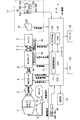
- FIG. 1 is a diagram showing an overview of a mixer vehicle management system according to an embodiment of the present invention.
- the present system includes a mixer truck 100, a management server 200, a user server 300, and a rental company server 400.
- the mixer truck 100 is a vehicle that carries mortar, ready-mixed concrete or the like (hereinafter referred to as “raw concrete”) and transports it to a construction site for civil engineering or construction, such as a radio base station (not shown) and the Internet. 50, communication with the management server 200 is possible.
- the management server 200 is a server operated by a manufacturer of the mixer truck 100, for example, and can communicate with the mixer truck 100, the user server 300, and the rental company server 400 via the Internet 50.
- the management server 200 is installed to manage the degree of deterioration, the replacement time, and the life time of various parts of the mixer vehicle 100 and notify them.
- the user server 300 is a server operated by the owner of the mixer truck 100 (excluding the rental company), and can communicate with the management server 200 via the Internet 50.
- the rental company server 400 is a server operated by the rental company of the mixer truck 100 and can communicate with the management server 200 via the Internet 50.
- the management server 200 may be operated not by the manufacturer of the mixer vehicle 100 but by another entity such as the rental company.
- FIG. 2 is a plan view of the mixer truck 100
- FIG. 3 is a block diagram showing a hardware configuration of the mixer truck 100. The overall configuration of the mixer truck 100 will be described with reference to both drawings.
- the vehicle is a vehicle that is loaded with a live concrete in the mixer drum 2.
- the mixer vehicle 100 includes an operator cab 11, a gantry 1, a mixer drum 2 mounted on the gantry 1 and capable of mounting a raw control unit, a driving device 4 that rotationally drives the mixer drum 2, and a controller that controls each block of the mixer vehicle 100 10 and.
- the ready-mixed concrete is generated from materials such as cement, aggregate, water, etc. in the ready-mixed company's plant, is put into the mixer drum 2 of the mixer truck 100, and is agitated by the rotational drive of the mixer drum 2.
- the mixer drum 2 is a bottomed cylindrical container that is rotatably mounted on the gantry 1.
- the mixer drum 2 is rotatably supported by a drum roller (not shown) that is rotatably installed on the gantry 1.
- the mixer drum 2 is mounted such that the rotating shaft faces the front-rear direction of the vehicle.
- the mixer drum 2 is mounted so as to be inclined forward and backward so as to gradually increase toward the rear of the vehicle.
- An opening is formed at the rear end of the mixer drum 2, and raw food can be charged and discharged from the opening.
- the mixer drum 2 is rotationally driven using a traveling engine 3 mounted on the mixer vehicle 100 as a power source.
- the driving device 4 is driven by the rotation of the engine 3 and rotationally drives the mixer drum 2 by the fluid pressure of the working fluid.
- the rotational movement of the crankshaft in the engine 3 is caused by a power take-out mechanism 9 (PTO: Power-Take-Off) for constantly taking power from the engine 3 and a drive shaft 8 connecting the power take-out mechanism 9 and the drive device 4. It is transmitted to the driving device 4.
- PTO Power-Take-Off
- the power take-out mechanism 9 is provided with a rotation sensor 9a that detects the rotation speed and transmits a rotation speed signal corresponding to the detected rotation speed to the controller 10.
- the rotation sensor 9a may be provided so as to detect the rotational speed of the drive shaft 8.
- the driving device 4 hydraulic oil is used as the working fluid. Instead of hydraulic oil, other incompressible fluids may be used as the hydraulic fluid.
- the driving device 4 is a hydraulic pump 5 as a fluid pressure pump that is driven by the engine 3 to discharge the working fluid, and a fluid pressure motor that is driven by the hydraulic pump 5 to rotationally drive the mixer drum 2.
- the hydraulic motor 6 is provided.
- the drive device 4 can forward / reverse and increase / decrease the mixer drum 2.
- the hydraulic pump 5 is rotationally driven by the power that is always taken out from the engine 3 through the power take-out mechanism 9. Therefore, the rotational speed of the hydraulic pump 5 is greatly affected by a change in the rotational speed of the engine 3 accompanying the traveling state of the vehicle. Therefore, the mixer vehicle 100 controls the operation of the hydraulic pump 5 and the hydraulic motor 6 by the controller 10 so that the mixer drum 2 is in the target rotation state according to the rotational speed of the engine 3.
- the hydraulic pump 5 is, for example, a swash plate type axial piston pump having a variable capacity.
- the hydraulic pump 5 receives the command signal from the controller 10 and switches the tilt angle of the pump to the forward rotation direction or the reverse rotation direction.
- the hydraulic pump 5 has a solenoid valve for adjusting the tilt angle. By switching the solenoid valve, the discharge direction and discharge capacity of the hydraulic pump 5 are adjusted.
- the hydraulic oil discharged from the hydraulic pump 5 is supplied to the hydraulic motor 6, and the hydraulic motor 6 rotates thereby.
- the mixer drum 2 is connected to the hydraulic motor 6 via a speed reducer 7. As a result, the mixer drum 2 rotates as the hydraulic motor 6 rotates.
- the hydraulic pressure of the hydraulic oil discharged from the hydraulic pump 5 varies depending on the amount of raw control mounted in the mixer drum 2 and the slump (a numerical value indicating the fluidity of the raw control).
- the hydraulic pump 5 is provided with a pressure sensor 5a (see FIG. 3) as a pressure detector that detects the pressure of discharged hydraulic oil.
- the pressure sensor 5a transmits a load pressure signal to the controller 10 in accordance with the detected pressure of the hydraulic oil.
- the pressure sensor 5a may be provided in the hydraulic motor 6 without being provided in the hydraulic pump 5, and the pressure of the hydraulic oil in the hydraulic motor 6 may be detected.
- the hydraulic motor 6 is, for example, a swash plate type axial piston motor having a variable capacity.
- the hydraulic motor 6 is rotationally driven in response to the supply of hydraulic oil discharged from the hydraulic pump 5.
- the hydraulic motor 6 includes an electromagnetic valve that receives a command signal from the controller 10 and adjusts the tilt angle of the motor. By switching this electromagnetic valve, the capacity of the hydraulic motor 6 is switched in two stages, a small capacity for high speed rotation and a large capacity for normal rotation.
- the hydraulic motor 6 is provided with a rotation sensor 6a that detects the rotation speed and transmits a rotation speed signal corresponding to the detected rotation speed to the controller 10.
- the rotation sensor 6 a can also detect the rotation direction of the hydraulic motor 6 and transmit a rotation direction signal corresponding to the detected rotation direction to the controller 10.
- the rotation sensor may be provided not in the hydraulic motor 6 but in the hydraulic pump 5 so that the rotation speed of the hydraulic pump 5 is detected and a rotation speed signal is transmitted to the controller 10.
- the controller 10 controls each block of the driving device 4 and other mixer vehicles 100.
- the controller 10 is a microcomputer having a CPU (Central Processing Unit) 110, an EEPROM (Electrically-Erasable Programmable Read-Only Memory) 120, and a RAM (Random Access Memory) 130.
- CPU Central Processing Unit
- EEPROM Electrically-Erasable Programmable Read-Only Memory
- RAM Random Access Memory
- the CPU 110 appropriately accesses the EEPROM 120, the RAM 130, etc. as necessary, and comprehensively controls each block of the mixer vehicle 100 while performing various arithmetic processes.
- the EEPROM 120 is a non-volatile memory in which firmware such as an OS, a program, and various parameters to be executed by the CPU 110 is fixedly stored.
- the RAM 130 is used as a work area for the CPU 110 and temporarily holds the OS, various applications being executed, and various data being processed.
- the CPU 110 has a rotation speed detection unit 111.
- the rotation speed detector 111 detects the rotation speed of the mixer drum 2 and generates rotation speed information indicating the rotation speed.
- the rotation speed detection unit 111 receives a rotation speed signal transmitted based on the rotation speed detected by the rotation sensor 6a, and based on the rotation speed indicated by the rotation speed signal, the rotation speed Is generated.
- the rotation speed detection unit 111 stores the rotation speed information in, for example, the EEPROM 120, and periodically transmits the rotation speed information to the management server 200 via the communication unit 21 described later, for example.
- the EEPROM 120 also stores a program for executing the rotation speed information generation process.
- the controller 10 is connected to a communication unit 21, an LCD (Liquid Crystal Display) 22, and a speaker 23.
- a communication unit 21 an LCD (Liquid Crystal Display) 22, and a speaker 23.
- LCD Liquid Crystal Display
- the communication unit 21 is a wireless communication unit that supports a wireless communication standard such as a wireless LAN, and performs communication processing with the management server 200.
- the LCD 22 is provided, for example, in the cab 11 and performs, for example, a predetermined color lighting process or blinking process in accordance with the notification information transmitted from the management server 200.
- the speaker 23 is provided in the cab 11, for example, and outputs predetermined alarm sounds having different volumes according to the notification information transmitted from the management server 200.
- the controller 10 is supplied with an ignition power supply when the engine 3 is started by the driver operating the ignition switch in the cab 11. Thereby, the controller 10 is activated by supplying power from the battery (not shown) to the controller 10.
- the mixer truck 100 also includes a water tank 12 in which water is stored, a water pressure pump 13 that sucks and discharges water in the water tank 12, and an on-off valve 14 provided between the water pressure pump 13 and the mixer drum 2. .
- a parking brake 31 and an operating device 32 for operating the mixer drum 2 are provided.
- the operation device 32 includes a knob-type operation switch 32a for switching the rotation direction and rotation speed of the mixer drum 2, a stop switch 32b for emergency stop of the rotation of the mixer drum 2, and the mixer drum 2 is automatically stirred and rotated. And an automatic agitation switch 32c.
- the operating device 32 includes a charging mode switch 32d for switching to a charging mode in which the raw material can be charged into the mixer drum 2, a slump readjustment switch 32e for readjusting the slump of the ready-mixed concrete in the mixer drum 2, and the mixer drum 2.
- a kneading switch 32f for kneading the raw cooking container for a predetermined time.
- a command signal is output from the operating device 32 to the controller 10 based on the driver operating the switches 32a to 32f. Based on the command signal, the controller 10 determines the target rotation state of the mixer drum 2, specifically, the rotation direction and the rotation speed.
- a rear operation device 38 for enabling the operation of the mixer drum 2 outside the mixer vehicle 100 is disposed at the rear of the mixer vehicle 100. Similar to the operation device 32, the rear operation device 38 includes a knob-type operation switch 38 a for switching the rotation direction and rotation speed of the mixer drum 2 and a stop switch 38 b for emergency stop of the rotation of the mixer drum 2. Provided.
- the rear portion of the mixer truck 100 (mixer drum 2) is discharged from the chute, which is a vertical member that can be moved up and down to guide the discharged raw concrete to the target unloading position, and from the mixer drum 2.
- a flow guide which is a member that collects raw kon on the chute, is also provided.
- the mixer drum 2 and the flow guide are sealed by a sealing member made of a resin such as rubber or nylon.
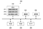
- FIG. 4 is a block diagram showing a hardware configuration of the management server 200.
- the management server 200 includes a CPU 210, a ROM 220, a RAM 230, a communication unit 240, a storage unit 250, and a timer 260.
- the CPU 210 appropriately accesses the EEPROM 120, the RAM 130, and the like as necessary, and performs overall control of each block of the management server 200 while performing various arithmetic processes.
- the ROM 220 is a non-volatile memory in which firmware such as an OS, a program, and various parameters to be executed by the CPU 110 is fixedly stored.
- the RAM 230 is used as a work area for the CPU 110 and temporarily holds the OS, various applications being executed, and various data being processed.
- the communication unit 240 is, for example, an NIC (Network Interface Card) for Ethernet, and is responsible for communication processing with the mixer vehicle 100, the user server 300, and the rental company server 400.
- NIC Network Interface Card
- the storage unit 250 is a non-volatile memory such as an HDD (Hard Disk Drive), a flash memory (SSD; Solid State Drive), or other solid-state memory.
- the storage unit 250 stores various applications and various data.
- the storage unit 250 stores the rotational speed information transmitted from the mixer truck 100, the operating time information of the mixer truck 100 generated based on the rotational speed information, and a plurality of threshold information related to the operating time.
- First threshold value and second threshold value deterioration level information (replacement time information and life time information) of various parts of the mixer truck 100, which is generated based on the operation time information, and the time information. Data such as broadcast information is stored.
- the second threshold value is greater than the first threshold value.
- the first threshold value is, for example, 30,000 hours, and the second threshold value is, for example, 35,000 hours, but is not limited thereto.
- the timer 260 is used for starting and ending various operations of the management server 200, and can also be used for an operation time calculation process described later.
- the CPU 210 includes an operation time calculation unit 211, an operation time determination unit 212, and a notification information generation unit 213.
- the operation time calculation unit 211 calculates the operation time of the mixer vehicle 100 based on the integrated value of the rotation speed indicated by the rotation speed information received from the mixer vehicle 100. For example, the operation time may be calculated based on a correspondence table indicating a correspondence relationship between the rotation speed and the operation time. Also, the operating time calculation unit 211 calculates the time during which the rotational speed is detected as the operating time only when the rotational speed information transmitted from the mixer vehicle 100 indicates a rotational speed greater than or equal to a predetermined value. Also good. In this case, the operating time calculation unit 211 starts the timer 260 when it is determined that the rotational speed is equal to or greater than a predetermined value, and counts the time until the rotational speed becomes less than the predetermined value. Then, an integrated value of the counted time is calculated as the operation time.
- the operating time determination unit 212 When the calculated operating time is not less than the first threshold and less than the second threshold, the operating time determination unit 212 generates replacement time information indicating replacement times of various components of the mixer truck 100, and the accumulated time When the value is equal to or greater than the second threshold, life time information indicating the life time of the various components is generated.
- the notification information generation unit 213 generates replacement time notification information and life time notification information based on the replacement time information and the life time information generated by the operation time determination unit 212, and the mixer vehicle 100, the user server 300, or the rental vehicle. Send to company server 400.
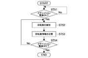
- FIG. 5 is a flowchart showing the flow of the rotational speed information generation process by the mixer vehicle 100.
- the CPU 110 determines whether or not the ignition power source is turned on (step 51).
- the CPU 110 determines the rotation speed of the hydraulic motor 6, that is, the rotation of the hydraulic motor 6 based on the rotation speed signal output from the rotation sensor 6a of the hydraulic motor 6. The number of rotations of the mixer drum 2 that rotates in conjunction with the drive is detected (step 52).
- the CPU 110 generates rotation speed information indicating the calculated rotation speed and stores it in, for example, the EEPROM 120 (step 53).
- the CPU 110 repeats the above processing until the ignition power is turned off (step 54).
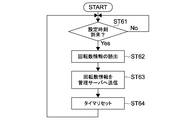
- FIG. 6 is a flowchart showing the flow of the rotational speed information transmission process by the mixer vehicle 100.
- the CPU 110 of the mixer vehicle 100 determines whether or not a time set at a predetermined time interval has arrived, such as once a month (step 61).
- the CPU 110 reads the rotation speed information from the EEPROM 120 (step 62).
- the CPU 110 transmits the read rotation speed information to the management server 200 through the communication unit 21, for example, via a base station (step 63).
- the CPU 110 resets the timer, and when the next set time comes, repeats the processing from step 62 onward.
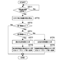
- FIG. 7 is a flowchart showing a flow of notification information transmission processing by the management server 200.
- the CPU 210 of the management server 200 determines whether or not the rotational speed information has been received from the mixer truck 100 (step 71).
- the CPU 210 (operation time calculation unit 211) stores the rotation speed information in the storage unit 250, and the rotation speed indicated by the rotation speed information (the correspondence table, Alternatively, the operation time of the mixer truck is calculated based on the predetermined number of revolutions counted by the timer 260 or the number of revolutions (step 72).
- the CPU 210 determines whether or not the operation time is equal to or greater than the first threshold (step 73).
- the CPU 210 determines whether the operation time is equal to or greater than the second threshold (step 74).
- the CPU 210 If it is determined that the operating time is less than the second threshold (No), the CPU 210 generates replacement time information indicating the replacement time of the components of the mixer truck 100 (step 75).
- the CPU 210 (notification information generation unit 213) generates replacement time notification information for notifying the replacement time based on the replacement time information, and the communication unit 240 generates the replacement time notification information from the mixer vehicle 100, the user server 300, or the rental. It transmits to the company server 400 (step 76).
- step 74 when it is determined in step 74 that the operation time is equal to or greater than the second threshold (Yes), the CPU 210 generates life time information indicating the life time of the components of the mixer truck 100 (step 77).
- the CPU 210 (notification information generation unit 213) generates life time notification information for notifying the life time based on the life time information, and uses the communication unit 240 to transmit the life time notification information to the mixer vehicle 100, the user server 300, or the rental. It transmits to the company server 400 (step 78).
- the components of the mixer vehicle 100 include, for example, the above-described mixer drum 2, engine 3, hydraulic pump (and oil filter) 5, hydraulic motor 6, speed reducer (gear box) 7, drive shaft 8 (and its cup).
- the power take-out mechanism (PTO) 9, and the drum roller although not shown, there are a hydraulic pipe, a drum blade, a drum shell, and the like.
- the replacement time information and the life time information may include the replacement time and the life time of the hydraulic oil of the hydraulic pump 5 and the grease-up time of each part such as the speed reducer (and the flange of the speed reducer).
- the first threshold value and the second threshold value differ depending on the respective components.
- the life of the mixer drum 2 drum ring
- the life of the hydraulic pump 5 and the hydraulic motor 6 is about 20 years
- the life of the hydraulic piping is about 2 years
- the life of the hydraulic oil is about 1 year.
- the life of the mixer vehicle 100 itself is about 20 years
- the first threshold value and the second threshold value for the operation time are set in accordance with the different lifespan and the replacement time calculated backward therefrom.
- the CPU 210 may generate the replacement time notification information and the life time notification information for each of the plurality of parts, and may add and transmit part information indicating which part the notification information is for which information.
- FIG. 8 is a flowchart showing a flow of notification processing by the mixer vehicle 100.
- the CPU 110 of the mixer truck 100 determines whether or not notification information has been received from the management server 200 (step 81).
- the CPU 110 determines whether or not the notification information is lifetime period notification information (step 82).
- the CPU 110 When it is determined that the notification information is life time notification information (Yes), the CPU 110 outputs a loud alarm from the speaker 23 and blinks the LCD 22 in a predetermined color (step 84).
- the CPU 110 when it is determined that the notification information is replacement time notification information (No), the CPU 110 outputs an alarm of a normal volume (a volume lower than the high volume) from the speaker 23 and also causes the LCD 22 to output the predetermined information.
- the color is turned on (step 83).
- the color in this case may be a color different from that in step 84 above.
- Either one of alarm output from the speaker 23 and lighting or blinking of the LCD 22 may be executed instead of both.
- the driver who is operating the mixer vehicle 100 can replace the various parts of the mixer vehicle 100 without stopping the operation even if the notification information is being received. It is possible to distinguish and grasp the life period and take appropriate measures.
- the processing in the figure is processing when the mixer vehicle 100 receives the notification information from the management server 200, but when the user server 300 or the rental company server 400 receives the notification information, similarly, for example, with different volume levels.
- An alarm output or notification information pop-up notification in a different display form may be executed.
- the user of the mixer truck 100 or the rental company can distinguish and grasp the replacement time and life time of various parts of the mixer truck 100 in use, and can order new parts based on the replacement time notification information.
- the operation of the mixer vehicle 100 can be stopped together with an order for a new part based on the life time notification information.
- the mixer truck 100 determines which part is the notification information based on the part information added to the notification information, and Accordingly, the output mode of the alarm and the display mode of the display may be changed.
- the mixer truck management system can appropriately detect the degree of deterioration (and replacement time or life time) of various components of the mixer truck 100 without human intervention. , It can be notified.
- the mixer vehicle 100 detects the rotation speed based on the rotation speed signal output from the rotation sensor 6a of the hydraulic motor 6.
- the mixer vehicle 100 may also monitor the rotation speed signal output from the rotation sensor 9a provided in the PTO 9.
- the mixer vehicle 100 can detect the rotation of the engine 3 (that is, the hydraulic pump 5 linked thereto) from the rotation speed signal from the rotation sensor 9a, and the hydraulic motor 6 (mixer drum 2) from the rotation speed signal from the rotation sensor 6a.
- rotation speed information indicating the rotation speed of components for example, the hydraulic pump 5, the drive shaft 8, and the PTO 9) interposed between the hydraulic motor 6 and the engine 3 is generated and sent to the management server 200. You may send it.
- the management server 200 may generate notification information by determining the degree of deterioration (replacement time and life time) of the parts interposed between the hydraulic motor 6 and the engine 3 based on the rotation speed information.
- the case where the rotation of the hydraulic pump 5 can be detected and the rotation of the hydraulic motor 6 cannot be detected is, for example, a case where a switching valve (not shown) interposed therebetween is set to a neutral position.
- the mixer vehicle management system cannot detect the rotation of the mixer drum 2 (the rotational power of the engine is not transmitted to the mixer drum), not only the degree of deterioration of the component whose rotation is detected but also its upstream (the component) Further, the degree of deterioration of components existing on the engine 3 side can be calculated from the rotation speed and notified.
- the notification information is generated based on the rotation speed of the mixer drum 2, but in addition to this, the discharged amount of the live mixer of the mixer drum 2 is detected in the mixer vehicle 100 and the discharged amount information is transmitted to the management server 200. May be. Based on the discharge amount information, the management server 200 replaces the life of the flow guide and the seal member that seals the mixer drum 2 and the flow guide, and replaces the life due to wear of the chute. The time may be determined, and the notification information may be transmitted accordingly.
- the management server 200 uses the first threshold value and the second threshold value as threshold information.
- the viscosity of the hydraulic oil of the hydraulic pump 5 varies depending on the temperature. The lower the temperature, the higher the viscosity. As a result of the difference in viscosity, the load applied to the hydraulic pump 5 also varies, resulting in a difference in replacement time and life time.
- the management server 200 may vary the first threshold value and the second threshold value depending on the air temperature during operation of the mixer vehicle 100. That is, the mixer vehicle 100 acquires the position information of the mixer vehicle 100 by, for example, a GPS (Global Positioning System) device or the like, and transmits it to the management server 200.
- a plurality of different first threshold values and second threshold values corresponding to each other are stored and it is determined that the operating time is equal to or greater than the first threshold value or equal to or greater than the second threshold value corresponding to the position information received from the mixer vehicle 100
- the replacement time information or the life time information may be generated.
- the temperature information indicated by the thermometer is transmitted to the management server 200 instead of the position information, and the management server 200 is based on the temperature information.
- Corresponding first and second threshold values may be selected.
- the management server 200 transmits the notification information to the mixer vehicle 100.
- the management vehicle 200 When the mixer vehicle 100 receives the life time notification information, the management vehicle 200 outputs a loud alarm and blinks the LCD 22.
- the management server 200 may transmit a function restriction signal that restricts at least a part of the function of the mixer truck 100 to the mixer truck 100.
- the management server 200 transmits to the mixer vehicle 100 an input restriction signal that restricts the input of the live concrete to the mixer drum 2 but permits the discharge, to the mixer vehicle 100. May execute only the discharge processing based on the above. That is, in this case, switching from the discharge mode to the charging mode is prohibited.
- the management server 200 does not transmit the limit signal, but the mixer vehicle 100 executes the notification process based on the reception of the life time notification signal and restricts the input mode by itself. Good.
- the mixer vehicle 100 detects the rotation speed of the mixer drum 2 based on the rotation speed of the hydraulic pump 5 or the hydraulic motor 6 and transmits the rotation speed information to the management server 200.
- the mixer vehicle 100 may detect the discharge pressure of the hydraulic pump 5 in addition to or instead of it, and transmit the discharge pressure information indicating the discharge pressure to the management server 200.
- the management server 200 may calculate the operating time by integrating the time during which the discharge pressure indicated by the discharge pressure information is equal to or greater than a predetermined value.
- the management server 200 generates deterioration information (replacement time / life time information) of various parts based on the rotation speed information received from the mixer vehicle 100, and generates notification information.
- the process of generating the degradation degree information (replacement time / life time) and the notification information generation process may be executed by the mixer vehicle 100.
- the mixer vehicle 100 may transmit the generated notification information to the user server 300 or the rental company server 400 directly or via the management server 200.
Landscapes
- Engineering & Computer Science (AREA)
- Mechanical Engineering (AREA)
- Transportation (AREA)
- Health & Medical Sciences (AREA)
- Public Health (AREA)
- Chemical & Material Sciences (AREA)
- Combustion & Propulsion (AREA)
- Structural Engineering (AREA)
- Preparation Of Clay, And Manufacture Of Mixtures Containing Clay Or Cement (AREA)
- Road Paving Machines (AREA)
Abstract
Priority Applications (3)
| Application Number | Priority Date | Filing Date | Title |
|---|---|---|---|
| NZ728238A NZ728238A (en) | 2014-06-17 | 2015-06-17 | Mixer truck management system, mixer truck management server, mixer truck and mixer truck management method |
| JP2016529392A JPWO2015194577A1 (ja) | 2014-06-17 | 2015-06-17 | ミキサ車管理システム、ミキサ車管理サーバ、ミキサ車及びミキサ車管理方法 |
| AU2015277896A AU2015277896A1 (en) | 2014-06-17 | 2015-06-17 | Mixer truck management system, mixer truck management server, mixer truck and mixer truck management method |
Applications Claiming Priority (2)
| Application Number | Priority Date | Filing Date | Title |
|---|---|---|---|
| JP2014-124562 | 2014-06-17 | ||
| JP2014124562 | 2014-06-17 |
Publications (1)
| Publication Number | Publication Date |
|---|---|
| WO2015194577A1 true WO2015194577A1 (fr) | 2015-12-23 |
Family
ID=54935557
Family Applications (1)
| Application Number | Title | Priority Date | Filing Date |
|---|---|---|---|
| PCT/JP2015/067393 Ceased WO2015194577A1 (fr) | 2014-06-17 | 2015-06-17 | Système de gestion de camion malaxeur, serveur de gestion de camion malaxeur, camion malaxeur et procédé de gestion de camion malaxeur |
Country Status (4)
| Country | Link |
|---|---|
| JP (1) | JPWO2015194577A1 (fr) |
| AU (1) | AU2015277896A1 (fr) |
| NZ (1) | NZ728238A (fr) |
| WO (1) | WO2015194577A1 (fr) |
Cited By (6)
| Publication number | Priority date | Publication date | Assignee | Title |
|---|---|---|---|---|
| JP2016084105A (ja) * | 2014-10-29 | 2016-05-19 | Kyb株式会社 | ミキサ車 |
| CN106168794A (zh) * | 2016-08-30 | 2016-11-30 | 湖南奥科网络技术股份有限公司 | 一种搅拌站的远程控制方法及装置 |
| JP2018001658A (ja) * | 2016-07-06 | 2018-01-11 | 大成建設株式会社 | 生コンクリートの納入および打設管理システム |
| CN111164316A (zh) * | 2017-09-25 | 2020-05-15 | 下西技研工业株式会社 | 铰链以及铰链的监控方法 |
| CN111164510A (zh) * | 2017-09-25 | 2020-05-15 | 下西技研工业株式会社 | 铰链以及铰链的监控方法 |
| WO2023139841A1 (fr) * | 2022-01-20 | 2023-07-27 | 川崎重工業株式会社 | Système de détermination de durée de vie pour une pompe à pression hydraulique |
Citations (5)
| Publication number | Priority date | Publication date | Assignee | Title |
|---|---|---|---|---|
| JPS59151832U (ja) * | 1983-03-31 | 1984-10-11 | 日野自動車株式会社 | パワ−テ−クオフ切換え装置 |
| JPH11153217A (ja) * | 1997-11-25 | 1999-06-08 | Jatco Corp | 自動変速機の故障検出装置 |
| JP2002133208A (ja) * | 2000-10-25 | 2002-05-10 | Kitagawa Iron Works Co Ltd | 生コンプラントにおける部品手配システム |
| JP2007521997A (ja) * | 2004-02-13 | 2007-08-09 | アールエス・ソリューションズ・エルエルシー | 運搬車でスランプを計算し、報告する方法およびシステム |
| JP2010120454A (ja) * | 2008-11-18 | 2010-06-03 | Pioneer Electronic Corp | 車両用走行音生成装置、車両走行音生成方法、車両用走行音生成プログラムおよび車両用走行音生成プログラムを格納した記録媒体 |
Family Cites Families (1)
| Publication number | Priority date | Publication date | Assignee | Title |
|---|---|---|---|---|
| JP2658553B2 (ja) * | 1990-10-26 | 1997-09-30 | 日立工機株式会社 | 遠心分離機用回転体の寿命管理方法 |
-
2015
- 2015-06-17 WO PCT/JP2015/067393 patent/WO2015194577A1/fr not_active Ceased
- 2015-06-17 AU AU2015277896A patent/AU2015277896A1/en not_active Abandoned
- 2015-06-17 NZ NZ728238A patent/NZ728238A/en not_active IP Right Cessation
- 2015-06-17 JP JP2016529392A patent/JPWO2015194577A1/ja active Pending
Patent Citations (5)
| Publication number | Priority date | Publication date | Assignee | Title |
|---|---|---|---|---|
| JPS59151832U (ja) * | 1983-03-31 | 1984-10-11 | 日野自動車株式会社 | パワ−テ−クオフ切換え装置 |
| JPH11153217A (ja) * | 1997-11-25 | 1999-06-08 | Jatco Corp | 自動変速機の故障検出装置 |
| JP2002133208A (ja) * | 2000-10-25 | 2002-05-10 | Kitagawa Iron Works Co Ltd | 生コンプラントにおける部品手配システム |
| JP2007521997A (ja) * | 2004-02-13 | 2007-08-09 | アールエス・ソリューションズ・エルエルシー | 運搬車でスランプを計算し、報告する方法およびシステム |
| JP2010120454A (ja) * | 2008-11-18 | 2010-06-03 | Pioneer Electronic Corp | 車両用走行音生成装置、車両走行音生成方法、車両用走行音生成プログラムおよび車両用走行音生成プログラムを格納した記録媒体 |
Cited By (10)
| Publication number | Priority date | Publication date | Assignee | Title |
|---|---|---|---|---|
| JP2016084105A (ja) * | 2014-10-29 | 2016-05-19 | Kyb株式会社 | ミキサ車 |
| JP2018001658A (ja) * | 2016-07-06 | 2018-01-11 | 大成建設株式会社 | 生コンクリートの納入および打設管理システム |
| CN106168794A (zh) * | 2016-08-30 | 2016-11-30 | 湖南奥科网络技术股份有限公司 | 一种搅拌站的远程控制方法及装置 |
| CN111164316A (zh) * | 2017-09-25 | 2020-05-15 | 下西技研工业株式会社 | 铰链以及铰链的监控方法 |
| CN111164510A (zh) * | 2017-09-25 | 2020-05-15 | 下西技研工业株式会社 | 铰链以及铰链的监控方法 |
| US11072955B2 (en) | 2017-09-25 | 2021-07-27 | Simotec Co., Ltd. | Hinge and hinge monitoring method |
| US11365574B2 (en) | 2017-09-25 | 2022-06-21 | Simotec Co., Ltd. | Hinge and hinge monitoring method |
| WO2023139841A1 (fr) * | 2022-01-20 | 2023-07-27 | 川崎重工業株式会社 | Système de détermination de durée de vie pour une pompe à pression hydraulique |
| JP2023105968A (ja) * | 2022-01-20 | 2023-08-01 | 川崎重工業株式会社 | 液圧ポンプの寿命判定システム |
| JP7762582B2 (ja) | 2022-01-20 | 2025-10-30 | 川崎重工業株式会社 | 液圧ポンプの寿命判定システム |
Also Published As
| Publication number | Publication date |
|---|---|
| JPWO2015194577A1 (ja) | 2017-06-15 |
| AU2015277896A1 (en) | 2017-02-02 |
| NZ728238A (en) | 2018-06-29 |
Similar Documents
| Publication | Publication Date | Title |
|---|---|---|
| WO2015194577A1 (fr) | Système de gestion de camion malaxeur, serveur de gestion de camion malaxeur, camion malaxeur et procédé de gestion de camion malaxeur | |
| US11679529B2 (en) | Mixer vehicle with concrete drum modes | |
| WO2013031759A1 (fr) | Camion malaxeur | |
| JP5656931B2 (ja) | ミキサ車 | |
| JP5593258B2 (ja) | 運搬車でスランプを計算し、報告する方法およびシステム | |
| US10744676B2 (en) | Concrete mixer and controls therefor for controlling drum rotation | |
| WO2017179626A1 (fr) | Véhicule mélangeur et système de gestion de véhicule mélangeur | |
| WO2016068020A1 (fr) | Véhicule mélangeur | |
| US20240293958A1 (en) | Concrete drum modes | |
| CA2582805A1 (fr) | Alarme de condition du fluide hydraulique d'une automobile | |
| CN102581957A (zh) | 一种搅拌车的随车物料计量指示的控制方法、装置及系统 | |
| WO2019172031A1 (fr) | Système de détermination d'état de fonctionnement de camion mélangeur | |
| JP5688208B2 (ja) | ミキサ車 | |
| WO2015194578A1 (fr) | Système de gestion de camion malaxeur, serveur de gestion de camion malaxeur, camion malaxeur et procédé de gestion de camion malaxeur | |
| CA3172448A1 (fr) | Systemes et methodes de commande du debit de dechargement de matieres agricoles | |
| JP6697278B2 (ja) | 運行管理装置及び運行管理方法 | |
| JP6483990B2 (ja) | ミキサ車 | |
| JP2024162910A (ja) | ミキサドラムの制御装置 | |
| JP2024162909A (ja) | ミキサドラムの制御装置 |
Legal Events
| Date | Code | Title | Description |
|---|---|---|---|
| 121 | Ep: the epo has been informed by wipo that ep was designated in this application |
Ref document number: 15810159 Country of ref document: EP Kind code of ref document: A1 |
|
| ENP | Entry into the national phase |
Ref document number: 2016529392 Country of ref document: JP Kind code of ref document: A |
|
| NENP | Non-entry into the national phase |
Ref country code: DE |
|
| ENP | Entry into the national phase |
Ref document number: 2015277896 Country of ref document: AU Date of ref document: 20150617 Kind code of ref document: A |
|
| 122 | Ep: pct application non-entry in european phase |
Ref document number: 15810159 Country of ref document: EP Kind code of ref document: A1 |