WO2015194579A1 - Poudre de métal revêtu de carbone, pâte électroconductrice contenant une poudre de métal revêtu de carbone, composant électronique stratifié utilisant ladite pâte, et procédé de fabrication de poudre de métal revêtu de carbone - Google Patents
Poudre de métal revêtu de carbone, pâte électroconductrice contenant une poudre de métal revêtu de carbone, composant électronique stratifié utilisant ladite pâte, et procédé de fabrication de poudre de métal revêtu de carbone Download PDFInfo
- Publication number
- WO2015194579A1 WO2015194579A1 PCT/JP2015/067401 JP2015067401W WO2015194579A1 WO 2015194579 A1 WO2015194579 A1 WO 2015194579A1 JP 2015067401 W JP2015067401 W JP 2015067401W WO 2015194579 A1 WO2015194579 A1 WO 2015194579A1
- Authority
- WO
- WIPO (PCT)
- Prior art keywords
- carbon
- metal powder
- metal
- coated
- nickel
- Prior art date
- Legal status (The legal status is an assumption and is not a legal conclusion. Google has not performed a legal analysis and makes no representation as to the accuracy of the status listed.)
- Ceased
Links
Images





Classifications
-
- B—PERFORMING OPERATIONS; TRANSPORTING
- B22—CASTING; POWDER METALLURGY
- B22F—WORKING METALLIC POWDER; MANUFACTURE OF ARTICLES FROM METALLIC POWDER; MAKING METALLIC POWDER; APPARATUS OR DEVICES SPECIALLY ADAPTED FOR METALLIC POWDER
- B22F1/00—Metallic powder; Treatment of metallic powder, e.g. to facilitate working or to improve properties
-
- B—PERFORMING OPERATIONS; TRANSPORTING
- B22—CASTING; POWDER METALLURGY
- B22F—WORKING METALLIC POWDER; MANUFACTURE OF ARTICLES FROM METALLIC POWDER; MAKING METALLIC POWDER; APPARATUS OR DEVICES SPECIALLY ADAPTED FOR METALLIC POWDER
- B22F1/00—Metallic powder; Treatment of metallic powder, e.g. to facilitate working or to improve properties
- B22F1/05—Metallic powder characterised by the size or surface area of the particles
- B22F1/052—Metallic powder characterised by the size or surface area of the particles characterised by a mixture of particles of different sizes or by the particle size distribution
-
- B—PERFORMING OPERATIONS; TRANSPORTING
- B22—CASTING; POWDER METALLURGY
- B22F—WORKING METALLIC POWDER; MANUFACTURE OF ARTICLES FROM METALLIC POWDER; MAKING METALLIC POWDER; APPARATUS OR DEVICES SPECIALLY ADAPTED FOR METALLIC POWDER
- B22F1/00—Metallic powder; Treatment of metallic powder, e.g. to facilitate working or to improve properties
- B22F1/10—Metallic powder containing lubricating or binding agents; Metallic powder containing organic material
- B22F1/107—Metallic powder containing lubricating or binding agents; Metallic powder containing organic material containing organic material comprising solvents, e.g. for slip casting
-
- B—PERFORMING OPERATIONS; TRANSPORTING
- B22—CASTING; POWDER METALLURGY
- B22F—WORKING METALLIC POWDER; MANUFACTURE OF ARTICLES FROM METALLIC POWDER; MAKING METALLIC POWDER; APPARATUS OR DEVICES SPECIALLY ADAPTED FOR METALLIC POWDER
- B22F1/00—Metallic powder; Treatment of metallic powder, e.g. to facilitate working or to improve properties
- B22F1/14—Treatment of metallic powder
- B22F1/142—Thermal or thermo-mechanical treatment
-
- B—PERFORMING OPERATIONS; TRANSPORTING
- B22—CASTING; POWDER METALLURGY
- B22F—WORKING METALLIC POWDER; MANUFACTURE OF ARTICLES FROM METALLIC POWDER; MAKING METALLIC POWDER; APPARATUS OR DEVICES SPECIALLY ADAPTED FOR METALLIC POWDER
- B22F1/00—Metallic powder; Treatment of metallic powder, e.g. to facilitate working or to improve properties
- B22F1/16—Metallic particles coated with a non-metal
-
- B—PERFORMING OPERATIONS; TRANSPORTING
- B22—CASTING; POWDER METALLURGY
- B22F—WORKING METALLIC POWDER; MANUFACTURE OF ARTICLES FROM METALLIC POWDER; MAKING METALLIC POWDER; APPARATUS OR DEVICES SPECIALLY ADAPTED FOR METALLIC POWDER
- B22F9/00—Making metallic powder or suspensions thereof
- B22F9/02—Making metallic powder or suspensions thereof using physical processes
- B22F9/04—Making metallic powder or suspensions thereof using physical processes starting from solid material, e.g. by crushing, grinding or milling
-
- B—PERFORMING OPERATIONS; TRANSPORTING
- B22—CASTING; POWDER METALLURGY
- B22F—WORKING METALLIC POWDER; MANUFACTURE OF ARTICLES FROM METALLIC POWDER; MAKING METALLIC POWDER; APPARATUS OR DEVICES SPECIALLY ADAPTED FOR METALLIC POWDER
- B22F9/00—Making metallic powder or suspensions thereof
- B22F9/02—Making metallic powder or suspensions thereof using physical processes
- B22F9/12—Making metallic powder or suspensions thereof using physical processes starting from gaseous material
-
- B—PERFORMING OPERATIONS; TRANSPORTING
- B22—CASTING; POWDER METALLURGY
- B22F—WORKING METALLIC POWDER; MANUFACTURE OF ARTICLES FROM METALLIC POWDER; MAKING METALLIC POWDER; APPARATUS OR DEVICES SPECIALLY ADAPTED FOR METALLIC POWDER
- B22F9/00—Making metallic powder or suspensions thereof
- B22F9/02—Making metallic powder or suspensions thereof using physical processes
- B22F9/14—Making metallic powder or suspensions thereof using physical processes using electric discharge
-
- B—PERFORMING OPERATIONS; TRANSPORTING
- B23—MACHINE TOOLS; METAL-WORKING NOT OTHERWISE PROVIDED FOR
- B23K—SOLDERING OR UNSOLDERING; WELDING; CLADDING OR PLATING BY SOLDERING OR WELDING; CUTTING BY APPLYING HEAT LOCALLY, e.g. FLAME CUTTING; WORKING BY LASER BEAM
- B23K1/00—Soldering, e.g. brazing, or unsoldering
- B23K1/0008—Soldering, e.g. brazing, or unsoldering specially adapted for particular articles or work
- B23K1/0016—Soldering of electronic components
-
- B—PERFORMING OPERATIONS; TRANSPORTING
- B23—MACHINE TOOLS; METAL-WORKING NOT OTHERWISE PROVIDED FOR
- B23K—SOLDERING OR UNSOLDERING; WELDING; CLADDING OR PLATING BY SOLDERING OR WELDING; CUTTING BY APPLYING HEAT LOCALLY, e.g. FLAME CUTTING; WORKING BY LASER BEAM
- B23K35/00—Rods, electrodes, materials, or media, for use in soldering, welding, or cutting
- B23K35/02—Rods, electrodes, materials, or media, for use in soldering, welding, or cutting characterised by mechanical features, e.g. shape
- B23K35/0222—Rods, electrodes, materials, or media, for use in soldering, welding, or cutting characterised by mechanical features, e.g. shape for use in soldering or brazing
- B23K35/0244—Powders, particles or spheres; Preforms made therefrom
- B23K35/025—Pastes, creams or slurries
-
- C—CHEMISTRY; METALLURGY
- C22—METALLURGY; FERROUS OR NON-FERROUS ALLOYS; TREATMENT OF ALLOYS OR NON-FERROUS METALS
- C22C—ALLOYS
- C22C19/00—Alloys based on nickel or cobalt
- C22C19/002—Alloys based on nickel or cobalt with copper as the next major constituent
-
- C—CHEMISTRY; METALLURGY
- C22—METALLURGY; FERROUS OR NON-FERROUS ALLOYS; TREATMENT OF ALLOYS OR NON-FERROUS METALS
- C22C—ALLOYS
- C22C19/00—Alloys based on nickel or cobalt
- C22C19/03—Alloys based on nickel or cobalt based on nickel
-
- C—CHEMISTRY; METALLURGY
- C22—METALLURGY; FERROUS OR NON-FERROUS ALLOYS; TREATMENT OF ALLOYS OR NON-FERROUS METALS
- C22C—ALLOYS
- C22C5/00—Alloys based on noble metals
- C22C5/06—Alloys based on silver
-
- C—CHEMISTRY; METALLURGY
- C22—METALLURGY; FERROUS OR NON-FERROUS ALLOYS; TREATMENT OF ALLOYS OR NON-FERROUS METALS
- C22C—ALLOYS
- C22C9/00—Alloys based on copper
-
- H—ELECTRICITY
- H01—ELECTRIC ELEMENTS
- H01B—CABLES; CONDUCTORS; INSULATORS; SELECTION OF MATERIALS FOR THEIR CONDUCTIVE, INSULATING OR DIELECTRIC PROPERTIES
- H01B1/00—Conductors or conductive bodies characterised by the conductive materials; Selection of materials as conductors
- H01B1/02—Conductors or conductive bodies characterised by the conductive materials; Selection of materials as conductors mainly consisting of metals or alloys
-
- H—ELECTRICITY
- H01—ELECTRIC ELEMENTS
- H01B—CABLES; CONDUCTORS; INSULATORS; SELECTION OF MATERIALS FOR THEIR CONDUCTIVE, INSULATING OR DIELECTRIC PROPERTIES
- H01B1/00—Conductors or conductive bodies characterised by the conductive materials; Selection of materials as conductors
- H01B1/20—Conductive material dispersed in non-conductive organic material
- H01B1/22—Conductive material dispersed in non-conductive organic material the conductive material comprising metals or alloys
-
- H—ELECTRICITY
- H01—ELECTRIC ELEMENTS
- H01F—MAGNETS; INDUCTANCES; TRANSFORMERS; SELECTION OF MATERIALS FOR THEIR MAGNETIC PROPERTIES
- H01F27/00—Details of transformers or inductances, in general
- H01F27/28—Coils; Windings; Conductive connections
- H01F27/2804—Printed windings
-
- H—ELECTRICITY
- H01—ELECTRIC ELEMENTS
- H01G—CAPACITORS; CAPACITORS, RECTIFIERS, DETECTORS, SWITCHING DEVICES, LIGHT-SENSITIVE OR TEMPERATURE-SENSITIVE DEVICES OF THE ELECTROLYTIC TYPE
- H01G4/00—Fixed capacitors; Processes of their manufacture
- H01G4/002—Details
- H01G4/005—Electrodes
- H01G4/008—Selection of materials
-
- H—ELECTRICITY
- H01—ELECTRIC ELEMENTS
- H01G—CAPACITORS; CAPACITORS, RECTIFIERS, DETECTORS, SWITCHING DEVICES, LIGHT-SENSITIVE OR TEMPERATURE-SENSITIVE DEVICES OF THE ELECTROLYTIC TYPE
- H01G4/00—Fixed capacitors; Processes of their manufacture
- H01G4/002—Details
- H01G4/005—Electrodes
- H01G4/008—Selection of materials
- H01G4/0085—Fried electrodes
-
- H—ELECTRICITY
- H01—ELECTRIC ELEMENTS
- H01G—CAPACITORS; CAPACITORS, RECTIFIERS, DETECTORS, SWITCHING DEVICES, LIGHT-SENSITIVE OR TEMPERATURE-SENSITIVE DEVICES OF THE ELECTROLYTIC TYPE
- H01G4/00—Fixed capacitors; Processes of their manufacture
- H01G4/002—Details
- H01G4/018—Dielectrics
- H01G4/06—Solid dielectrics
- H01G4/08—Inorganic dielectrics
- H01G4/12—Ceramic dielectrics
-
- B—PERFORMING OPERATIONS; TRANSPORTING
- B22—CASTING; POWDER METALLURGY
- B22F—WORKING METALLIC POWDER; MANUFACTURE OF ARTICLES FROM METALLIC POWDER; MAKING METALLIC POWDER; APPARATUS OR DEVICES SPECIALLY ADAPTED FOR METALLIC POWDER
- B22F2301/00—Metallic composition of the powder or its coating
- B22F2301/10—Copper
-
- B—PERFORMING OPERATIONS; TRANSPORTING
- B22—CASTING; POWDER METALLURGY
- B22F—WORKING METALLIC POWDER; MANUFACTURE OF ARTICLES FROM METALLIC POWDER; MAKING METALLIC POWDER; APPARATUS OR DEVICES SPECIALLY ADAPTED FOR METALLIC POWDER
- B22F2301/00—Metallic composition of the powder or its coating
- B22F2301/15—Nickel or cobalt
-
- B—PERFORMING OPERATIONS; TRANSPORTING
- B22—CASTING; POWDER METALLURGY
- B22F—WORKING METALLIC POWDER; MANUFACTURE OF ARTICLES FROM METALLIC POWDER; MAKING METALLIC POWDER; APPARATUS OR DEVICES SPECIALLY ADAPTED FOR METALLIC POWDER
- B22F2301/00—Metallic composition of the powder or its coating
- B22F2301/40—Intermetallics other than rare earth-Co or -Ni or -Fe intermetallic alloys
-
- B—PERFORMING OPERATIONS; TRANSPORTING
- B22—CASTING; POWDER METALLURGY
- B22F—WORKING METALLIC POWDER; MANUFACTURE OF ARTICLES FROM METALLIC POWDER; MAKING METALLIC POWDER; APPARATUS OR DEVICES SPECIALLY ADAPTED FOR METALLIC POWDER
- B22F2302/00—Metal Compound, non-Metallic compound or non-metal composition of the powder or its coating
- B22F2302/40—Carbon, graphite
-
- B—PERFORMING OPERATIONS; TRANSPORTING
- B22—CASTING; POWDER METALLURGY
- B22F—WORKING METALLIC POWDER; MANUFACTURE OF ARTICLES FROM METALLIC POWDER; MAKING METALLIC POWDER; APPARATUS OR DEVICES SPECIALLY ADAPTED FOR METALLIC POWDER
- B22F2302/00—Metal Compound, non-Metallic compound or non-metal composition of the powder or its coating
- B22F2302/45—Others, including non-metals
-
- B—PERFORMING OPERATIONS; TRANSPORTING
- B22—CASTING; POWDER METALLURGY
- B22F—WORKING METALLIC POWDER; MANUFACTURE OF ARTICLES FROM METALLIC POWDER; MAKING METALLIC POWDER; APPARATUS OR DEVICES SPECIALLY ADAPTED FOR METALLIC POWDER
- B22F2303/00—Functional details of metal or compound in the powder or product
- B22F2303/40—Layer in a composite stack of layers, workpiece or article
-
- B—PERFORMING OPERATIONS; TRANSPORTING
- B22—CASTING; POWDER METALLURGY
- B22F—WORKING METALLIC POWDER; MANUFACTURE OF ARTICLES FROM METALLIC POWDER; MAKING METALLIC POWDER; APPARATUS OR DEVICES SPECIALLY ADAPTED FOR METALLIC POWDER
- B22F2998/00—Supplementary information concerning processes or compositions relating to powder metallurgy
- B22F2998/10—Processes characterised by the sequence of their steps
-
- B—PERFORMING OPERATIONS; TRANSPORTING
- B22—CASTING; POWDER METALLURGY
- B22F—WORKING METALLIC POWDER; MANUFACTURE OF ARTICLES FROM METALLIC POWDER; MAKING METALLIC POWDER; APPARATUS OR DEVICES SPECIALLY ADAPTED FOR METALLIC POWDER
- B22F2999/00—Aspects linked to processes or compositions used in powder metallurgy
-
- B—PERFORMING OPERATIONS; TRANSPORTING
- B23—MACHINE TOOLS; METAL-WORKING NOT OTHERWISE PROVIDED FOR
- B23K—SOLDERING OR UNSOLDERING; WELDING; CLADDING OR PLATING BY SOLDERING OR WELDING; CUTTING BY APPLYING HEAT LOCALLY, e.g. FLAME CUTTING; WORKING BY LASER BEAM
- B23K35/00—Rods, electrodes, materials, or media, for use in soldering, welding, or cutting
- B23K35/22—Rods, electrodes, materials, or media, for use in soldering, welding, or cutting characterised by the composition or nature of the material
- B23K35/24—Selection of soldering or welding materials proper
- B23K35/30—Selection of soldering or welding materials proper with the principal constituent melting at less than 1550°C
- B23K35/3033—Ni as the principal constituent
-
- B—PERFORMING OPERATIONS; TRANSPORTING
- B23—MACHINE TOOLS; METAL-WORKING NOT OTHERWISE PROVIDED FOR
- B23K—SOLDERING OR UNSOLDERING; WELDING; CLADDING OR PLATING BY SOLDERING OR WELDING; CUTTING BY APPLYING HEAT LOCALLY, e.g. FLAME CUTTING; WORKING BY LASER BEAM
- B23K35/00—Rods, electrodes, materials, or media, for use in soldering, welding, or cutting
- B23K35/22—Rods, electrodes, materials, or media, for use in soldering, welding, or cutting characterised by the composition or nature of the material
- B23K35/36—Selection of non-metallic compositions, e.g. coatings or fluxes; Selection of soldering or welding materials, conjoint with selection of non-metallic compositions, both selections being of interest
- B23K35/3612—Selection of non-metallic compositions, e.g. coatings or fluxes; Selection of soldering or welding materials, conjoint with selection of non-metallic compositions, both selections being of interest with organic compounds as principal constituents
-
- B—PERFORMING OPERATIONS; TRANSPORTING
- B23—MACHINE TOOLS; METAL-WORKING NOT OTHERWISE PROVIDED FOR
- B23K—SOLDERING OR UNSOLDERING; WELDING; CLADDING OR PLATING BY SOLDERING OR WELDING; CUTTING BY APPLYING HEAT LOCALLY, e.g. FLAME CUTTING; WORKING BY LASER BEAM
- B23K35/00—Rods, electrodes, materials, or media, for use in soldering, welding, or cutting
- B23K35/22—Rods, electrodes, materials, or media, for use in soldering, welding, or cutting characterised by the composition or nature of the material
- B23K35/36—Selection of non-metallic compositions, e.g. coatings or fluxes; Selection of soldering or welding materials, conjoint with selection of non-metallic compositions, both selections being of interest
- B23K35/3612—Selection of non-metallic compositions, e.g. coatings or fluxes; Selection of soldering or welding materials, conjoint with selection of non-metallic compositions, both selections being of interest with organic compounds as principal constituents
- B23K35/3613—Polymers, e.g. resins
-
- H—ELECTRICITY
- H01—ELECTRIC ELEMENTS
- H01F—MAGNETS; INDUCTANCES; TRANSFORMERS; SELECTION OF MATERIALS FOR THEIR MAGNETIC PROPERTIES
- H01F27/00—Details of transformers or inductances, in general
- H01F27/28—Coils; Windings; Conductive connections
- H01F27/2804—Printed windings
- H01F2027/2809—Printed windings on stacked layers
-
- H—ELECTRICITY
- H01—ELECTRIC ELEMENTS
- H01F—MAGNETS; INDUCTANCES; TRANSFORMERS; SELECTION OF MATERIALS FOR THEIR MAGNETIC PROPERTIES
- H01F41/00—Apparatus or processes specially adapted for manufacturing or assembling magnets, inductances or transformers; Apparatus or processes specially adapted for manufacturing materials characterised by their magnetic properties
- H01F41/02—Apparatus or processes specially adapted for manufacturing or assembling magnets, inductances or transformers; Apparatus or processes specially adapted for manufacturing materials characterised by their magnetic properties for manufacturing cores, coils, or magnets
- H01F41/04—Apparatus or processes specially adapted for manufacturing or assembling magnets, inductances or transformers; Apparatus or processes specially adapted for manufacturing materials characterised by their magnetic properties for manufacturing cores, coils, or magnets for manufacturing coils
- H01F41/041—Printed circuit coils
-
- H—ELECTRICITY
- H01—ELECTRIC ELEMENTS
- H01G—CAPACITORS; CAPACITORS, RECTIFIERS, DETECTORS, SWITCHING DEVICES, LIGHT-SENSITIVE OR TEMPERATURE-SENSITIVE DEVICES OF THE ELECTROLYTIC TYPE
- H01G4/00—Fixed capacitors; Processes of their manufacture
- H01G4/002—Details
- H01G4/005—Electrodes
- H01G4/012—Form of non-self-supporting electrodes
-
- H—ELECTRICITY
- H01—ELECTRIC ELEMENTS
- H01G—CAPACITORS; CAPACITORS, RECTIFIERS, DETECTORS, SWITCHING DEVICES, LIGHT-SENSITIVE OR TEMPERATURE-SENSITIVE DEVICES OF THE ELECTROLYTIC TYPE
- H01G4/00—Fixed capacitors; Processes of their manufacture
- H01G4/30—Stacked capacitors
Definitions
- the present invention is a carbon-coated metal powder suitable for forming an internal conductor (internal electrode), a terminal electrode or the like of a laminated electronic component, a conductive paste containing the carbon-coated metal powder, and the same.
- the present invention relates to a multilayer electronic component.
- the present invention also relates to a method for producing a carbon-coated metal powder. In particular, after melting and evaporating a metal material, the supplied carbon source is subjected to endothermic decomposition to rapidly cool the metal vapor, thereby In parallel with the deposition of carbon, a carbon coating film is formed on the surface of the metal nucleus.
- Ceramic multilayer electronic components such as multilayer capacitors and multilayer inductors, and ceramic multilayer substrates are generally laminated with multiple layers of unfired ceramic green sheets such as dielectrics and magnetic materials and internal conductor paste layers, which are fired simultaneously at high temperatures. It is manufactured by. Conventionally, noble metals have been mainly used as the inner conductor, but in recent years, base metal materials such as nickel are often used.
- Nickel particles when fired in a non-oxidizing atmosphere such as an inert atmosphere or a reducing atmosphere to prevent oxidation, are sintered at a low temperature of 400 ° C. or lower, even if they are single crystal particles with relatively low activity. Start sintering and shrinking. On the other hand, the temperature at which the ceramic layer begins to sinter is generally much higher than this, for example about 1200 ° C. for barium titanate. Thus, since the shrinkage behavior of the two is different, when the internal conductor paste containing nickel powder and the ceramic sheet are fired simultaneously, the ceramic layer does not shrink together with the nickel film. There was a problem that delamination and cracks were likely to occur.
- Patent Documents 1 and 2 As one of the techniques for solving the above-mentioned problem, for example, it has been proposed to increase the sintering start temperature of nickel particles by coating or containing nickel particles with carbon (Patent Documents 1 and 2).
- Patent Document 1 after a nickel powder is produced by a gas phase hydrogen reduction method or the like, a carbon coating film is formed on the surface of the nickel powder by bringing a hydrocarbon gas and the nickel powder into contact at 300 to 600 ° C. A metal powder is disclosed.
- Patent Document 2 discloses carbon-containing nickel particles in which a dispersion containing nickel particles and a polyol is heated at 150 to 350 ° C. to adsorb carbon on the surfaces of the nickel particles and / or to allow carbon to penetrate into the nickel particles. A powder is disclosed.
- Patent Documents 3 and 4 describe that nickel particles coated with carbon are generated by cooling a metal vapor generated by melting and evaporating a metal raw material in an atmosphere containing a hydrocarbon gas such as methane gas. Is disclosed.
- the particle size distribution of the nickel particles obtained by the methods of Patent Documents 3 and 4 is very wide, and the nickel particles having a narrow particle size distribution required for the inner conductor described above are used. Cann't get. It is estimated that this is because it is difficult to uniformly cool the metal vapor generated by melting and evaporating the metal raw material, and the timing of nickel nucleus generation is different.
- the carbon-containing nickel powder of Patent Document 2 has been proposed for the purpose of improving the shrinkage characteristics, and although the shrinkage start temperature can be increased to 931 ° C. or 1007 ° C., it rapidly increases when the shrinkage start temperature is reached. Since it starts to shrink, the problem that delamination and cracks are likely to occur between the internal conductor layer and the ceramic layer during firing performed at a high temperature of 1200 ° C. or higher has not been sufficiently solved.
- Patent Documents 5 and 6 disclose inventions aimed at improving the shrinkage characteristics of nickel powder.
- the nickel powder is not coated with carbon, but nickel oxide or nickel hydroxide is coated to improve the shrinkage characteristics of the nickel powder.
- the shrinkage behavior at a low temperature of 400 ° C. or less is taken into consideration, and the shrinkage behavior up to 1200 ° C. is not taken into account. The problem of being likely to occur has not been sufficiently solved.
- Patent Documents 5 and 6 since nickel oxide or nickel hydroxide exists and the state of the coating film on the surface of the nickel particles is not analyzed in detail by X-ray photoelectron spectroscopy (XPS, ESCA), the shrinkage The improvement in characteristics is not sufficient, and the problem that delamination and cracks are likely to occur as described above has not been sufficiently solved.
- XPS X-ray photoelectron spectroscopy
- the present invention has been made to solve the above-mentioned problems, and is a carbon-coated metal powder having a small amount of impurities and a narrow particle size distribution, which is used as an inner conductor of a laminated electronic component and a conductive property for electrode formation.
- An object of the present invention is to provide a carbon-coated metal powder capable of forming a laminated electronic component with few defects such as delamination and cracks when used in a paste.
- Another object of the present invention is to provide a conductive paste containing such a carbon-coated metal powder and a laminated electronic component using the conductive paste.
- Another object of the present invention is to provide a method for producing a carbon-coated metal powder with a small amount of impurities and a narrow particle size distribution.
- the carbon-coated metal powder according to the present invention is a carbon-coated metal powder having a metal powder and a carbon-coated film that coats the metal powder,
- D50 is 300 nm or less
- the oxygen content is a weight ratio of the oxygen component to the unit weight of the carbon-coated metal powder, and is not more than 1500 ppm per 1 m 2 / g of the specific surface area of the powder.
- the carbon-coated metal powder of the present invention is a carbon-coated metal powder having nickel or a nickel-based powder containing nickel as a main component and a carbon-coated film covering the nickel-based powder
- the oxygen content is a weight ratio of the oxygen component to the unit weight of the carbon-coated metal powder, and is not more than 1500 ppm per 1 m 2 / g of the specific surface area of the powder.
- the peak position at the position of 11 nm from the particle surface toward the center is lower than the peak position attributed to 1 s of carbon atoms at the position of 1 nm from the particle surface toward the center. It is a carbon-coated metal powder that has shifted to.
- the shift toward the low energy side is preferably 0.08 eV or more, and it is preferable that there are no peaks attributed to nickel oxide and nickel hydroxide.
- This carbon-coated metal powder is sometimes referred to as “carbon-coated nickel-based powder”.
- This carbon-coated metal powder (carbon-coated nickel-based powder) further has the above-mentioned characteristics (D50, SD value, X defined by TMA measurement) defined for the carbon-coated metal powder characterized by TMA or the like. It is preferable.
- the method for producing a carbon-coated metal powder according to the present invention includes: A metal vapor generating step of heating the metal raw material in the reaction vessel and melting and evaporating the metal raw material to generate metal vapor; A transport step of transporting the metal vapor from the reaction vessel to the cooling pipe by a carrier gas; A metal nucleus precipitation step of cooling the metal vapor in the cooling pipe to precipitate metal nuclei; A metal nucleus growth step for growing the deposited metal nuclei; A method for producing a carbon-coated metal powder comprising: In the metal nucleus deposition step, a carbon source is supplied into the cooling pipe, and the metal vapor is rapidly cooled by endothermic decomposition, so that the carbon coating on the surface of the metal nucleus is performed in parallel with the deposition of the metal nucleus. This is a manufacturing method for forming a film.
- the carbon-coated metal powder according to the present invention can be obtained by the above production method.
- the carbon-coated metal powder of the present invention is a fine powder with few impurities and a narrow particle size distribution, and suitable sintering behavior when used as an internal conductor for laminated electronic components and a conductive paste for electrode formation. This makes it possible to form an extremely thin electrode with few voids. Therefore, a laminated electronic component with few defects such as delamination and cracks can be obtained using the conductive paste.
- the carbon-coated metal powder of the present invention can be obtained by the above production method.
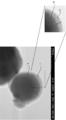
- FIG. 2 is a TEM (transmission electron microscope) image of the carbon-coated metal powder obtained in Example 1.
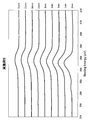
- FIG. 2 is a TMA chart of carbon-coated metal powders obtained in Examples 1 to 5, 8, and 11. 6 is a TMA chart of carbon-coated metal powders obtained in Comparative Examples 1 and 3 to 5.
- FIG. 2 is a TEM (transmission electron microscope) image of the carbon-coated metal powder obtained in Example 1.
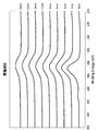
- FIG. 2 is a TMA chart of carbon-coated metal powders obtained in Examples 1 to 5, 8, and 11. 6 is a TMA chart of carbon-coated metal powders obtained in Comparative Examples 1 and 3 to 5.
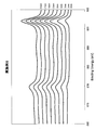
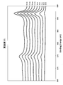
- FIG. 6 is a diagram showing a change in strength of the carbon 1s peak showing the surface analysis result by ESCA measured between the binding energies of 276 to 294 eV in the carbon-coated metal powder obtained in Example 5, depending on the argon ion etching depth.
- FIG. 10 is a diagram showing a change in strength of the carbon 1s peak showing the surface analysis result by ESCA measured between the binding energies 276 to 294 eV in the carbon-coated metal powder obtained in Example 8 according to the argon ion etching depth. .
- FIG. 6 is a diagram showing the results of surface analysis by ESCA measured with a binding energy of 850 to 880 eV in the carbon-coated metal powder obtained in Example 5.
- FIG. 9 is a diagram showing the results of surface analysis by ESCA measured between the binding energies of 850 to 880 eV in the carbon-coated metal powder obtained in Example 8.
- FIG. 6 is a diagram showing the results of surface analysis by ESCA measured between a binding energy of 850 and 880 eV in the carbon-coated metal powder obtained in Example 11.
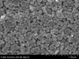
- 2 is an SEM (scanning electron microscope) image of the carbon-coated metal powder obtained in Example 1.
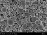
- 4 is a SEM image of the carbon-coated metal powder obtained in Comparative Example 3.
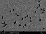
- 2 is an SEM image of a fired film formed using the carbon-coated metal powder obtained in Example 1.
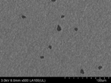
- 2 is a SEM image of a fired film formed using the carbon-coated metal powder obtained in Example 1-1.
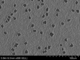
- 6 is an SEM image of a fired film formed using the carbon-coated metal powder obtained in Comparative Example 3.
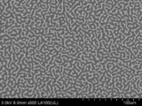
- 10 is a SEM image of a fired film formed using the carbon-coated metal powder obtained in Comparative Example 5.
- the carbon-coated metal powder according to the present invention includes a metal powder and a carbon-coated film that coats the metal powder, and particularly forms an internal conductor (internal electrode) or a terminal electrode of a laminated electronic component.
- the present invention is not limited to this, and may be used for various other purposes.
- a base metal is preferable and the metal containing at least any one among nickel and copper is especially preferable.
- the metal powder nickel powder substantially consisting only of nickel, copper powder consisting essentially of copper, and powder consisting of nickel and copper are particularly preferable.
- “consisting essentially of nickel” means that the metal powder contains more than 98 wt% nickel.
- “consisting essentially of copper” means that the metal powder contains more than 98 wt% copper.
- the powder composed of nickel and copper nickel powder containing 2 to 20 wt% of copper is particularly preferable.
- the carbon-coated metal powder has a D50 of 300 nm or less when D10, D50, and D90 are 10%, 50%, and 90%, respectively, in the volume-based integrated fraction of laser diffraction particle size distribution measurement.
- the SD value indicated by D10) / (D50) is 1.5 or less.
- D50 is preferably not less than 100 nm and not more than 300 nm, more preferably not less than 150 nm and not more than 300 nm. Further, the SD value is desirably as small as possible, but it is difficult to reduce the SD value to 0.5 or less from the viewpoint of manufacturing.
- the thickness of the carbon coating film can be determined from a TEM observation image, and is preferably 2 to 15 nm. If it is in the said range, the sintering inhibitory effect is sufficient and the quantity of the carbon which remains after baking can be restrained low.
- the oxygen content of the carbon-coated metal powder is a weight ratio of the oxygen component to the unit weight of the carbon-coated metal powder, and is 1500 ppm or less, preferably 1000 ppm or less, more preferably 800 ppm or less, per 1 m 2 / g of the specific surface area of the powder. Therefore, it is desirable that the amount be as small as possible, but it is difficult to make it 10 ppm or less.
- the specific surface area is a specific surface area measured by the BET method.
- “1500 ppm or less per 1 m 2 / g of the specific surface area of the powder” means that when the specific surface area of the carbon-coated metal powder is am 2 / g, the oxygen content is (a ⁇ 1500 relative to the unit weight of the carbon-coated metal powder. ) Ppm or less, that is, 1500 ⁇ 10 ⁇ 6 g or less per 1 m 2 of the surface area of the carbon-coated metal powder.
- the carbon-coated metal powder varies depending on the particle size, it is desirable that the carbon content is 0.5 to 3.50 wt% and the oxygen content is 1 wt% or less so that it is minimized.
- the content of impurities including oxygen is preferably suppressed to 3 wt% or less. If it is in the said range, the carbon and impurity amount which remain
- X (%) (X 200 ° C./X MAX ) ⁇ 100 (1)
- room temperature means about 25 to 30 ° C.
- X MAX is the maximum shrinkage, and refers to the maximum shrinkage in the range from room temperature to 1200 ° C.
- X 200 ° C. is the maximum value of the difference between the maximum shrinkage and the minimum shrinkage in the temperature range of 200 ° C.
- the difference between the maximum shrinkage and the minimum shrinkage at a temperature range of 200 ° C. at which the curve representing the heat shrinkage with respect to the temperature rise changes most rapidly is X 200 ° C. It becomes. That is, X (%) calculated from the above formula (1) is an index indicating how rapidly the carbon-coated metal powder contracted in the range from room temperature to 1200 ° C., and the larger the value, the more It turns out that it contracts rapidly.
- Carbon-coated metal powder (carbon-coated nickel-based powder)
- the carbon-coated metal powder is a carbon-coated metal powder having a nickel-based powder and a carbon-coated film covering the nickel-based powder, and the carbon-coated metal powder having the following characteristics by surface analysis by ESCA will be described. .
- the carbon-coated metal powder is referred to as “carbon-coated nickel-based powder”.
- Nickel-based powder is a nickel-based powder substantially consisting of nickel or mainly composed of nickel.
- consisting essentially of nickel means that the metal powder contains more than 98 wt% nickel.
- mainly composed of nickel means that the metal powder contains more than 50 wt% of nickel.
- the nickel-based powder containing nickel as a main component is preferably a nickel powder containing copper, particularly a nickel powder containing 2 to 20 wt% of copper.
- the carbon-coated nickel-based powder has an oxygen content of the carbon-coated nickel-based powder of 1500 ppm or less, preferably 1000 ppm or less per 1 m 2 / g of the specific surface area of the powder in terms of the weight ratio of the oxygen component to the carbon-coated metal powder of unit weight. More preferably, it is 800 ppm or less and is desirably as low as possible, but it is difficult to make it 10 ppm or less. About carbon content and impurity content containing oxygen, it demonstrates similarly to the above-mentioned carbon covering metal powder.
- the peak position attributed to 1 s of carbon atoms changes from the particle surface toward the center in the surface analysis by ESCA.
- the peak position at a position of 11 nm from the particle surface toward the center is shifted to the low energy side with respect to the peak position at a position of 1 nm from the particle surface toward the center.
- the shift to the low energy side is preferably 0.08 eV or more, and a carbon-coated nickel-based powder having a shift amount of 1.00 eV or less is easily obtained.
- the peak attributed to 1 s of carbon atoms is a peak existing in the vicinity of a binding energy of about 284.6 eV.
- the reason for shifting in this way is considered as follows.
- the position of 1 nm from the particle surface toward the center is a portion close to the surface of the carbon coating film, and a large amount of carbon is present.
- the position of 11 nm from the particle surface toward the center is near the interface between the carbon coating film and the nickel-based powder, and there is a nickel carbide layer of carbon and nickel.
- the shift occurs because the electronic state is different at positions of 1 nm and 11 nm from the particle surface toward the center. Since the nickel carbide layer continuously changes from nickel to a carbon layer, a strong carbon coating film having high adhesive strength is formed.
- the carbon-coated nickel-based powder of the present invention preferably has no peaks attributed to nickel oxide and nickel hydroxide on the particle surface in the surface analysis by ESCA.
- the peak attributed to nickel oxide is a peak existing in the vicinity of a binding energy of about 854.0 eV.
- the peak attributed to nickel hydroxide is a peak existing in the vicinity of a binding energy of about 855.7 eV.
- the carbon-coated nickel-based powder having the above-described configuration, a carbon-coated nickel-based powder with extremely few impurities can be obtained.
- the carbon-coated nickel-based powder further includes characteristics such as the thickness of the carbon-coated film described as preferable for the above-described carbon-coated metal powder characterized by TMA characteristics and the like. It is preferable to have the same characteristics (TMA characteristics and the like) as the carbon-coated metal powder, and thereby further effects can be obtained.
- the method for producing a carbon-coated metal powder according to the present invention includes a metal vapor generation step in which a metal raw material is heated in a reaction vessel to melt and evaporate the metal raw material to generate metal vapor, and the metal vapor is generated by a carrier gas.
- a carbon source is supplied into the cooling pipe, and the metal vapor is rapidly cooled by endothermic decomposition, and the metal nucleus is deposited on the surface of the metal nucleus in parallel with the precipitation of the metal nucleus.
- a carbon coating film is formed, and the carbon-coated metal powder of the present invention can be obtained by this production method.
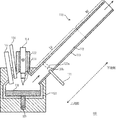
- FIG. 1 is a schematic view showing an example of the configuration of a plasma apparatus 100 used in the method for producing a carbon-coated metal powder according to the present invention.
- a metal raw material is accommodated in the reaction vessel 101.
- the feed port 107 replenishes the inside of the reaction vessel 101 with a metal raw material.
- a predetermined amount of the metal raw material is prepared in the reaction vessel 101, and after starting the operation of the apparatus, depending on the amount reduced from the reaction vessel 101 as metal vapor. As needed, the metal raw material is replenished into the reaction vessel 101 from the feed port 107. Therefore, the plasma apparatus 100 of the present invention can produce carbon-coated metal powder continuously for a long time.
- a plasma torch 102 is disposed above the reaction vessel 101, and a plasma generation gas is supplied to the plasma torch 102 via a supply pipe (not shown).
- the plasma torch 102 generates a plasma 103 between a cathode 104 (cathode) and an anode (anode) (not shown) provided inside the plasma torch 102, and then cathode 104 (cathode) and anode 105 (anode).
- the plasma 103 is generated between them, and at least a part of the metal raw material in the reaction vessel 101 is melted by the heat of the plasma 103 to generate a molten metal 108. Further, the plasma torch 102 evaporates a part of the molten metal 108 by the heat of the plasma 103 and generates metal vapor.
- the carrier gas supply unit 106 supplies a carrier gas for transporting metal vapor into the reaction vessel 101.
- a cooling pipe 110 is connected to the reaction vessel 101.
- the metal vapor generated in the reaction vessel 101 is conveyed to the cooling pipe 110 by the carrier gas.
- the cooling pipe 110 sequentially includes an indirect cooling section IC for indirectly cooling the metal vapor and a direct cooling section DC for directly cooling the carbon-coated metal powder from the reaction vessel 101 side (upstream side).
- the indirect cooling section IC is composed of a double tube of an inner tube 112 and an outer tube 113. Then, a cooling fluid is circulated in the space between the outer wall of the inner tube 112 and the inner wall of the outer tube 113, and the periphery of the cooling tube 110 (the inner tube 112) is cooled or heated.
- the temperature of the indirect cooling section IC is controlled.
- Indirect cooling is performed on the coated metal powder.
- the carbon source supplied for forming the carbon coating film is described below.
- the cooling fluid the above-described carrier gas and other gases can be used, and liquids such as water, hot water, methanol, ethanol, or a mixture thereof can also be used.
- water or hot water it is preferable to use water or hot water as the cooling fluid.
- the cooling fluid has been described.
- an external heater may be provided around the cooling pipe 110 to perform cooling or heating.
- a cooling fluid supplied from a cooling fluid supply unit (not shown) is jetted or mixed with the carbon-coated metal powder conveyed from the indirect cooling section IC to perform direct cooling.
- the cooling fluid used in the direct cooling section DC may be the same as or different from the cooling fluid used in the indirect cooling section IC, but is the same as the carrier gas from the viewpoint of ease of handling and cost. It is preferable to use a gas.
- the cooling fluid includes a liquid
- the liquid is introduced into the cooling pipe 110 (inner pipe 112) in a sprayed state.
- a cooling pipe having a larger opening cross-sectional area than that of the indirect cooling section IC may be adopted.
- the carrier gas that has passed through the indirect cooling section IC can be rapidly expanded to increase the cooling efficiency.
- specific cooling mechanisms of the indirect cooling section IC and the direct cooling section DC are omitted.
- known ones see Table 2002 as an example
- a convex portion or a concave portion may be provided on the inner wall of the inner pipe 112 of the cooling pipe 110 on the upstream side from a virtual surface 120b described later.
- the carbon source supply unit 111 is connected to an opening provided locally on the inner wall of the inner tube 112, and is provided so as to supply a carbon source as a carbon coating material of the carbon-coated metal powder into the indirect cooling compartment IC.
- the term “local” refers to a portion in the vicinity of the imaginary plane 120a, preferably a transverse zone having a width within 10 cm in the longitudinal direction of the cooling pipe 110, and more preferably a transverse zone having a width within 5 cm. .
- the size of the opening of the inner wall of the inner tube 112 to which the carbon source supply unit 111 is connected is preferably within 10 cm.
- a plurality of openings may be provided and the carbon source may be supplied from a plurality of locations in the vicinity of the virtual surface 120a.
- a carbon source may be supplied from two locations by providing further openings so as to face the openings in FIG.
- the carbon source supply unit 111 is preferably provided so as to be able to supply the carbon source in the vicinity of the virtual surface 120a, and is provided so that the carbon source can be supplied in the vicinity of the virtual surface 120a upstream of the virtual surface 120a. More preferred.
- the virtual surface 120a means that when the carbon source supply unit 111 is not provided, that is, when no carbon source is supplied to the indirect cooling compartment IC, many metal nuclei are deposited in the indirect cooling compartment IC. It is a position, for example, it can obtain
- a collector (not shown) is provided downstream of the cooling pipe 110.
- the carbon-coated metal powder conveyed further downstream from the cooling pipe 110 is separated from the carrier gas and collected by the collector. Note that the carrier gas separated by the collector may be reused by the carrier gas supply unit 106.
- FIG. 2 is a schematic view showing another example of the configuration of the plasma apparatus 100 used in the method for producing a carbon-coated metal powder according to the present invention. Here, only parts different from the plasma apparatus 100 shown in FIG. 1 will be described.
- the indirect cooling section IC includes a first indirect cooling section 114 in which metal vapor is transferred from the reaction vessel 101, and a second indirect disposed between the first indirect cooling section 114 and the direct cooling section DC.
- the cross-sectional area of the opening of the first indirect cooling section 114 is smaller than the cross-sectional area of the opening of the second indirect cooling section 115.
- the opening is a portion serving as a flow path through which the metal vapor is conveyed, and in FIG. 2 is a portion surrounded by the inner walls of the inner tubes 112a and 112b.
- the cross-sectional area is an opening area in a plane perpendicular to the longitudinal direction of the cooling pipe.
- each of the first indirect cooling section 114 and the second indirect cooling section 115 has a cylindrical shape, and the inner diameter of the first indirect cooling section 114 is smaller than the inner diameter of the second indirect cooling section 115. .
- the carbon source supply unit 111 is preferably provided so that the carbon source can be supplied into the second indirect cooling section 115, and the carbon source is supplied into the second indirect cooling section 115 in the vicinity of the first indirect cooling section 114. More preferably, it can be provided. In this case, the supply portion of the carbon source is after or immediately after the metal vapor is transferred from the first indirect cooling section 114 having a small cross-sectional area to the second indirect cooling section 115 having a large cross-sectional area. Is a portion where the concentration of the metal vapor rapidly decreases as the value increases rapidly.
- the indirect cooling compartment IC is configured by two sections having different cross-sectional areas, but may be configured by three or more sections having different cross-sectional areas.
- a metal raw material is put into the reaction vessel 101.
- the metal raw material is not particularly limited as long as it is a conductive substance containing the metal component of the target carbon-coated metal powder.
- the metal component include silver, gold, cadmium, cobalt, copper, iron, nickel, palladium, platinum, rhodium, ruthenium, tantalum, titanium, tungsten, zirconium, molybdenum, niobium, and the like.
- the metal raw material preferably has a boiling point higher than the decomposition temperature of the carbon source, more preferably 700 to 3600 ° C. Thereby, it becomes easy to make the inside of the cooling pipe 110 have an atmosphere higher than the decomposition temperature of the carbon source. Moreover, when it exceeds 3600 degreeC, it will become difficult to control a carbon coating film.
- a metal raw material a base metal that is more easily oxidized than a noble metal is preferable because the effect of the present invention can be enjoyed more, and a metal raw material containing at least one of nickel and copper is preferable. Particularly preferred.
- the metal raw material consists essentially of nickel (boiling point 2732 ° C.), substantially copper (boiling point 2567 ° C.), or a mixture, alloy or composite of nickel and copper.
- substantially only nickel means that the metal raw material contains more than 98 wt% nickel.
- “consisting essentially of copper” means that the metal raw material contains more than 98 wt% copper.
- a nickel metal raw material containing 2 to 20 wt% of copper is particularly preferable.
- a granular or massive metal material, alloy, or composite material having a size of several mm to several tens mm is particularly preferable.
- the metal raw material is heated, and the metal raw material is melted and evaporated to generate metal vapor.
- a plasma 103 is generated between the cathode 104 and the anode 105, and at least a part of the metal raw material in the reaction vessel 101 is melted by the heat of the plasma 103, thereby generating a molten metal 108 of the metal raw material.
- a part of the molten metal 108 is evaporated by the heat of the plasma 103 to generate metal vapor.
- the method for heating the metal raw material is preferably heated by plasma, but there is no particular limitation as long as the metal raw material can be melted and evaporated.
- the metal vapor generated in the reaction vessel 101 is conveyed to the cooling pipe 110 by the carrier gas.
- the carrier gas it is preferable to use an inert gas. Unless otherwise specified, nitrogen gas is used as the carrier gas in the following description.
- the carrier gas may be mixed with a reducing gas such as hydrogen, carbon monoxide, methane, or ammonia gas, or an organic compound such as alcohols or carboxylic acids as necessary. In order to improve / adjust the properties and characteristics of the material, components such as phosphorus and sulfur may be added. Note that the plasma generation gas used to generate plasma also functions as part of the carrier gas.
- the reaction vessel 101 it is preferable that no carbon source exists in the reaction vessel 101, and it is preferable to use a gas that does not contain a component that can be a carbon source such as methane as the carrier gas.
- the flow rate of the carrier gas is preferably controlled so that the metal concentration is 0.01 to 1 g / L. Thereby, metal vapor
- Metal nucleation process The metal vapor conveyed from the reaction vessel 101 is cooled in the cooling pipe 110. Thereby, metal nuclei are deposited from the metal vapor.
- the carbon source supplied into the cooling pipe 110 by the carbon source supply unit 111 is subjected to endothermic decomposition, and the metal vapor is rapidly cooled, so that the carbon coating on the surface of the metal nucleus is performed in parallel with the precipitation of the metal nucleus. Covering film formation is performed.
- the carbon source undergoes an endothermic reaction (endothermic decomposition) when it is decomposed.
- the decomposition temperature of the carbon source is preferably 700 to 3600 ° C. If it exceeds 3600 ° C., sublimation of graphite contained in the carbon coating film formed on the metal surface tends to occur, and the carbon coating film becomes difficult to control.
- hydrocarbons such as ethane, methane, propane, butane, ethylene, propylene and butylene, and alcohols such as ethanol and monoethylene glycol can be used. Any solid, liquid, or gaseous carbon source can be used, but a gaseous carbon source is preferably used.
- the carbon source can be easily decomposed to carbon alone.
- methane gas decomposition temperature of about 700 ° C.
- the decomposition temperature of the carbon source is preferably 100 ° C. or higher, more preferably 500 ° C. or higher, more preferably 1000 ° C. or higher, lower than the boiling point of the metal raw material to be used.
- methane gas as the metal source and carbon source.
- a carbon source decomposes
- this mixed gas may be called a carbon source.
- V / S (L / cm 2 ) is greater than 0, preferably 10 or less, more preferably 5
- the temperature of the carbon source to be supplied is not particularly limited as long as it is lower than the decomposition temperature of the carbon source, but it is not necessary to perform heating or the like in advance, for example, a carbon source at room temperature (25 to 30 ° C.) Can be used.
- the addition amount of the carbon source is preferably such that the carbon content is 0.1 to 5 wt% with respect to the metal amount of the produced carbon-coated metal powder.
- the carbon content is 0.1 to 5 wt% with respect to the metal amount of the produced carbon-coated metal powder.
- the metal vapor concentration is 0.05 g / L
- the flow rate of the carbon source is 7 minutes per minute. It is preferable to set it to ⁇ 25L.
- the metal nucleation step is preferably performed in an indirect cooling step for indirectly cooling the metal vapor.
- the indirect cooling process can be performed in the indirect cooling section IC of the cooling pipe 110.
- the cooling fluid is not ejected or mixed with the metal vapor, it becomes easy to supply the carbon source to the metal vapor existing at a specific position.
- the indirect cooling section IC the metal vapor in the carrier gas transferred into the cooling pipe 110 at a high temperature is cooled by radiation, and the metal nuclei generated in a stable and uniformly temperature-controlled atmosphere. As the growth and crystallization proceed, carbon-coated metal powder having a uniform particle diameter is easily generated in the carrier gas.
- the temperature is stably and uniformly controlled, the temperature of the metal vapor can be rapidly changed by the endothermic decomposition of the carbon source.
- metal vapor is conveyed from the reaction vessel 101 to the indirect cooling section IC of the cooling pipe 110.
- the concentration is high and the temperature is several thousand K (for example, 5000 K), but by indirect cooling (radiation cooling), The temperature drops to near the boiling point of the metal.
- the metal vapor is below the boiling point, it becomes droplets and metal nuclei begin to form. And many nuclei begin to precipitate almost simultaneously at a certain position in the indirect cooling section IC (referred to as a virtual plane in the present invention).
- the virtual plane depends on the type of metal or carbon source, the concentration of the metal vapor or carbon source, the flow rate of the carbon source or carrier gas, the temperature of the metal vapor or carrier gas or carbon source, the temperature distribution in the cooling pipe, etc. Although it is different and does not indicate a specific position, here, in order to facilitate understanding, the virtual surface when the carbon source is not supplied is 120a, and the virtual surface when the carbon source is supplied is 120b.
- the carbon source is supplied from the carbon source supply unit 111 to the metal vapor that has fallen to near the boiling point.
- a position for example, the imaginary surface 110b
- the carbon source it is preferable to supply the carbon source to a position where the decomposition temperature of methane is about 700 ° C. or higher and 3005 ° C. (the boiling point of nickel is 2732 ° C. + (2732 ° C. ⁇ 10%)) or lower.
- a carbon source is supplied to the upstream side in the vicinity of the virtual surface 110a.
- This carbon source is decomposed by being heated to a temperature higher than the decomposition temperature, takes heat from the metal vapor by an endothermic reaction at the time of decomposition of the carbon source, and rapidly cools the metal vapor.
- the temperature drops rapidly from the temperature near the boiling point, the metal vapor does not form droplets even when the temperature is lower than the boiling point, and becomes unstable (supersaturated state). Through this supersaturated state, the formation of metal nuclei occurs all at once. Thereby, the generation timing of metal nuclei is aligned, and the amount of metal nuclei increases.
- a carbon-coated metal powder having a small particle size and a narrow particle size distribution is obtained.
- the virtual surface 120b is usually near the position where the carbon source is supplied from the carbon supply unit 111.
- the upstream side in the vicinity of the virtual surface 120a is the virtual surface 120b.
- the indirect cooling step includes a first indirect cooling step and a second indirect cooling step in which indirect cooling is performed in a state where the concentration of the metal vapor in the first indirect cooling step is lowered. Then, in the second indirect cooling step, the metal vapor is rapidly cooled by endothermic decomposition of the carbon source, and the carbon coating film is formed on the surface of the metal nucleus in parallel with the precipitation of the metal nucleus. Is more preferable. Further, when the transition from the first indirect cooling step to the second indirect cooling step is performed, the volume of the metal vapor is rapidly expanded, so that the rapid cooling of the metal vapor is further enhanced by the auxiliary cooling by the volume expansion. Can do.
- the carbon source it is more preferable to supply the carbon source to a position that is not lower than the decomposition temperature of the carbon source and (melting point of the metal raw material + the melting point ⁇ 25%) ° C. or lower.
- the carbon source is methane, supply the carbon source to a position where the decomposition temperature is about 700 ° C. or higher and 1816 ° C. (1453 ° C. + (1453 ° C. ⁇ 25%) which is the melting point of nickel) or lower. Is more preferable.
- 1st indirect cooling process and 2nd indirect cooling process are realizable by using the plasma apparatus of FIG.
- indirect cooling is performed in a state where the concentration of metal vapor is high in the first indirect cooling section 114, and then indirect cooling is continued in a state where the concentration of metal vapor is decreased in the second indirect cooling section 115.
- a carbon source is supplied by the carbon source supply unit 111 in the second indirect cooling section 115, preferably in the vicinity of the first indirect cooling section 114 of the second indirect cooling section 115.
- the virtual surfaces 120a and 120b are substantially in the same position, for example, in the vicinity of the first indirect cooling section 114 of the second indirect cooling section 115.
- the generated metal nuclei are subsequently subjected to grain growth and crystallization in the indirect cooling section IC.
- Grain growth can be broadly divided into grain growth in which metal vapor around the nucleus progresses while precipitating on the surface of the nucleus, and grain growth in which a plurality of adjacent nuclei proceed while coalescing. The latter is considered to be dominant as an effect on the width of the particle size distribution.
- the carbon coating film is formed on the surface of the metal nucleus almost simultaneously with or at the latest of the formation of the metal nucleus, so that grain growth due to coalescence is suppressed. As a result, a carbon-coated metal powder having a uniform particle size with a very narrow particle size distribution can be obtained.
- the carbon-coated metal powder generated by being indirectly cooled in the indirect cooling section IC is directly cooled in the subsequent direct cooling section DC. Then, the carbon-coated metal powder directly cooled in the direct cooling section DC is conveyed further downstream from the cooling pipe 110, and separated and recovered by the carrier gas in the collector.
- the crystallinity of graphite is increased, and the sintering suppression effect is improved.
- the crystallinity of graphite can be evaluated by the peak intensity due to the G band of graphite in Raman spectrum measurement.
- the half width of the G band peak is 100 or less. When it exceeds 100, it will be in the state where many amorphous parts remained, and crystallinity will become inadequate.
- the heat treatment is performed, for example, at 180 to 1000 ° C. for 1 to 10 hours in an inert atmosphere, or at 180 to 400 ° C. for 1 to 10 hours in an air atmosphere.
- the preferred heat treatment temperature is 180 to 300 ° C., and heat aggregation occurs when the temperature exceeds 300 ° C., and the dispersibility tends to deteriorate.
- the heat treatment temperature is less than 180 ° C., the crystallinity of graphite is lowered, The effect of heat treatment is reduced.
- the carbon-coated metal powder obtained by the method for producing a carbon-coated metal powder according to the present invention has a small particle size and a narrow particle size distribution. Moreover, since the metal powder and the carbon coating film are not formed after the metal powder is formed as in the prior art, the metal powder and the carbon coating film are formed simultaneously. Can be reduced.
- the impurity is not a component intentionally contained, but a component that is inevitably mixed from raw materials, manufacturing processes, and the like, and usually includes chlorine, an alkali metal, and the like. Therefore, for example, when the carrier gas contains components such as phosphorus and sulfur in order to improve and adjust the properties and characteristics of the carbon-coated metal powder, these components are not called impurities.
- the impurity content varies depending on the particle diameter, but is preferably 3 wt% or less.
- the conductive paste according to the present invention contains the above-mentioned carbon-coated metal powder as a conductive powder, and is kneaded in a vehicle composed of a binder resin and a solvent.
- This conductive paste is particularly suitable for the formation of internal conductors (internal electrodes) of multilayer electronic components such as multilayer capacitors, multilayer inductors, multilayer actuators, etc.
- terminal electrodes and thick film conductor circuits of ceramic electronic components are used. It can also be used to form.
- the carbon-coated metal powder may be either a carbon-coated metal powder characterized by TMA characteristics or the like, or a carbon-coated nickel-based powder characterized by ESCA analysis. An example of the method for producing the conductive paste and the laminated electronic component will be described below.
- the carbon-coated metal powder according to the present invention, a binder resin, and a solvent are kneaded using a three-roll mill.
- the binder resin include cellulose resins such as ethyl cellulose and hydroxyethyl cellulose, acrylic resin, methacrylic resin, butyral resin, epoxy resin, phenol resin, rosin and the like, usually 1 to 15 parts by weight with respect to 100 parts by weight of conductive powder. It can be used in a blended degree.
- an alcohol solvent such as dihydrotapineol, a ketone solvent, an ether solvent, an ester solvent, a hydrocarbon solvent or the like, water, or a mixed solvent thereof can be appropriately selected and used.
- the amount of the solvent is appropriately blended according to the properties of the conductive powder, the type of resin, the coating method and the like, and is usually about 40 to 150 parts by weight with respect to 100 parts by weight of the conductive powder.
- the conductive paste of the present invention includes, in addition to the above-mentioned components, components that are usually blended, that is, ceramics containing the same or similar components as the ceramics contained in the ceramic sheet, glass, Alumina, silica, copper oxide, manganese oxide, metal oxides such as manganese oxide, inorganic powders such as montmorillonite, metal organic compounds, plasticizers, dispersants, surfactants, etc. may be appropriately blended according to the purpose. it can.
- a conductive paste is manufactured as described above.
- a conductive paste is printed in a predetermined pattern on an unfired ceramic green sheet as an unfired ceramic layer, dried to remove the solvent, and an internal conductor paste layer is formed.
- a plurality of unfired ceramic green sheets having the obtained internal conductor paste layer are stacked and pressed to obtain an unfired laminate in which unfired ceramic green sheets and internal conductor paste layers are alternately laminated.
- the laminate is cut into a predetermined shape, followed by a binder removal process in which the binder resin is burned and scattered, and then fired at a high temperature of about 1200 to 1400 ° C. to sinter the ceramic layer and form the inner conductor layer. Simultaneously, a ceramic body is obtained. Thereafter, terminal electrodes are baked on both end faces of the element body to obtain a laminated electronic component.
- the terminal electrode may be formed by applying a terminal electrode conductor paste to both end faces of the unfired laminated body cut into the predetermined shape, and then firing simultaneously with the laminated body.
- the carbon-coated metal powder By using the carbon-coated metal powder with few impurities, gas is hardly generated during firing, and a good fired film (internal conductor layer) can be obtained.
- the carbon-coated metal powder has a good carbon-coated film, the dispersibility in the conductive paste is improved, and the shrinkability during sintering is improved, so that the conductor layer and the ceramic layer Sintering shrinkage behavior is approximated and the occurrence of cracks and delamination is suppressed.
- the carbon-coated metal powder of the present invention has a narrow particle size distribution and a small average particle size, the fired film formed by applying and firing the conductive paste containing the carbon-coated metal powder has a thin film thickness. Even so, it has few holes (defects), is excellent in smoothness, denseness, and continuity, and the internal conductor layer can be thinned.
- the thickness of the inner conductor layer is, for example, 0.4 to 0.8 ⁇ m.
- the conductive paste containing the carbon-coated metal powder of the present invention when used for the production of laminated electronic components, it has a thin inner conductor layer that is dense and excellent in continuity, and is excellent. A laminated electronic component having characteristics can be obtained without causing structural defects such as cracks and delamination.
- Example 1 Carbon-coated metal powder was produced using the plasma apparatus 100 of FIG.
- the cooling pipe 110 includes an inner pipe 112a (first indirect cooling section 114) having an inner diameter of 3.8 cm, an inner pipe 112b (second indirect cooling section 115) having an inner diameter of 8 cm, and an inner pipe 112c having an inner diameter of 15 cm (directly).
- a combination with the cooling compartment DC) was used.
- the length of the inner tube 112a was 20 cm
- the length of the inner tube 112b was 22.5 cm
- the length of the inner tube 112c was 20 cm.
- a carbon source was supplied from a carbon source supply unit 111 having an inner diameter (supply port) of 0.32 cm on the downstream side of the second indirect cooling section 115 by 5 cm.
- the plasma apparatus having the above configuration is referred to as a plasma apparatus A.
- Nickel was used as the metal raw material, and the evaporation rate was 10 g per minute.
- Nitrogen gas was used as the carrier gas.
- the carrier gas passing through the cooling pipe was 200 L / min, and the metal concentration was controlled to be 0.05 g / L.
- As the carbon source a mixed gas containing 10% methane (hereinafter referred to as 10% methane gas) in argon gas (carrier gas) is used, the supply amount is 25 L / min, and the temperature of the supplied carbon source is room temperature (25 ⁇ 30 ° C). Supplying a carbon source, in a state in which metal vapor is transported, the temperature T beta position for supplying the carbon source (usually virtual surface 120a vicinity), was 1040 ° C..
- the temperature of the said position was 1100 degreeC temperature T ( alpha ) in the state in which the metal vapor
- T 1100 degreeC temperature
- Example 2 The experiment was performed in the same manner as in Example 1 except that the flow rate of the carbon source was changed to 7 L / min. T ⁇ was 1100 ° C. and T ⁇ was 1050 ° C.
- Example 3 The experiment was performed in the same manner as in Example 1 except that the flow rate of the carbon source was 6 L / min. T ⁇ was 1100 ° C. and T ⁇ was 1050 ° C.
- Example 4 The experiment was performed in the same manner as in Example 1 except that the flow rate of the carbon source was 40 L / min. T ⁇ was 1100 ° C. and T ⁇ was 1024 ° C.
- Example 5 The experiment was performed in the same manner as in Example 1 except that a mixed gas containing 3% propane in argon gas was used as the carbon source. T ⁇ was 1100 ° C. and T ⁇ was 1035 ° C.
- Example 6 Carbon-coated metal powder was produced using the plasma apparatus A. Silver was used as the metal raw material, and the evaporation rate was 100 g per minute. Nitrogen gas was used as the carrier gas, the carrier gas passing through the cooling pipe was 200 L / min, and the metal concentration was controlled to be 0.5 g / L. As the carbon source, 10% methane gas was used, the supply amount was 25 L / min, and the temperature of the supplied carbon source was room temperature (25-30 ° C.). T ⁇ was 750 ° C. and T ⁇ was 700 ° C.
- Example 7 Carbon-coated metal powder was produced using the plasma apparatus A. Copper was used as the metal raw material, and the evaporation rate was 15 g per minute. Nitrogen gas was used as the carrier gas, the carrier gas passing through the cooling pipe was 200 L / min, and the metal concentration was controlled to be 0.075 g / L. As the carbon source, 10% methane gas was used, the supply amount was 25 L / min, and the temperature of the supplied carbon source was room temperature (25-30 ° C.). T ⁇ was 920 ° C. and T ⁇ was 880 ° C.
- Example 8 Carbon-coated metal powder was produced using the plasma apparatus A.
- the metal raw material an alloy of nickel and copper (copper content 2 wt%) was used, and the evaporation rate was 10 g per minute.
- Nitrogen gas was used as the carrier gas, the carrier gas passing through the cooling pipe was 200 L / min, and the metal concentration was controlled to be 0.05 g / L.
- the carbon source 10% methane gas was used, the supply amount was 25 L / min, and the temperature of the supplied carbon source was room temperature (25-30 ° C.). T ⁇ was 1080 ° C. and T ⁇ was 1035 ° C.
- Example 9 Carbon-coated metal powder was produced using the plasma apparatus A.
- An alloy of nickel and copper (copper content of 20 wt%) was used as the metal raw material, and the evaporation rate was 12 g / min.
- Nitrogen gas was used as the carrier gas, the carrier gas passing through the cooling pipe was 200 L / min, and the metal concentration was controlled to be 0.06 g / L.
- As the carbon source 10% methane gas was used, the supply amount was 25 L / min, and the temperature of the supplied carbon source was room temperature (25-30 ° C.). T ⁇ was 1075 ° C. and T ⁇ was 1020 ° C.
- the cooling pipe 110 includes an inner pipe 112a (first indirect cooling section 114) having an inner diameter of 8.9 cm, an inner pipe 112b (second indirect cooling section 115) having an inner diameter of 10.3 cm, and an inner pipe 112c having an inner diameter of 22 cm.
- a combination with (direct cooling section DC) was used.
- the length of the inner tube 112a was 3.5 cm
- the length of the inner tube 112b was 46 cm
- the length of the inner tube 112c was 42.3 cm.
- a carbon source was supplied from a carbon source supply unit 111 having an inner diameter (supply port) of 1 cm downstream from the upstream end of the second indirect cooling section 115 by 10 cm.
- the plasma apparatus having the above configuration is referred to as a plasma apparatus B.
- Nickel was used as the metal raw material, and the evaporation rate was 85 g per minute.
- Nitrogen gas was used as the carrier gas.
- the carrier gas passing through the cooling pipe was 750 L / min, and the metal concentration was controlled to be 0.11 g / L.
- As the carbon source 10% methane gas was used, the supply amount was 20 L / min, and the temperature of the supplied carbon source was room temperature (25-30 ° C.). T ⁇ was 1780 ° C. and T ⁇ was 1500 ° C.
- Example 11 Using the plasma apparatus B, carbon-coated metal powder was produced. Nickel was used as the metal raw material, and the evaporation rate was 50 g per minute. Nitrogen gas was used as the carrier gas. The carrier gas passing through the cooling pipe was 750 L / min, and the metal concentration was controlled to 0.07 g / L. As the carbon source, a mixed gas containing 3% methane gas in argon gas was used, the supply rate was 103 L / min, and the temperature of the supplied carbon source was room temperature (25 to 30 ° C.). T ⁇ was 1650 ° C. and T ⁇ was 1380 ° C.
- Example 12 Carbon-coated metal powder was produced using the plasma apparatus 100 shown in FIG.
- the cooling pipe 110 includes an inner pipe 112a (first indirect cooling section 114) with an inner diameter of 8.9 cm, an inner pipe 112b (second indirect cooling section 115) with an inner diameter of 22 cm, and an inner pipe 112c (directly with an inner diameter of 22 cm).
- a combination with the cooling compartment DC) was used.
- the length of the inner tube 112a was 10.3 cm
- the length of the inner tube 112b was 22.5 cm
- the length of the inner tube 112c was 44.3 cm.
- a carbon source was supplied from a carbon source supply unit 111 having an inner diameter (supply port) of 1 cm on the downstream side of the second indirect cooling section 115 11 cm.
- Nickel was used as the metal raw material, and the evaporation rate was 85 g per minute.
- Nitrogen gas was used as the carrier gas.
- the carrier gas passing through the cooling pipe was 750 L / min, and the metal concentration was controlled to be 0.11 g / L.
- As the carbon source 10% methane gas was used, the supply amount was 20 L / min, and the temperature of the supplied carbon source was room temperature (25-30 ° C.). T ⁇ was 1780 ° C. and T ⁇ was 1470 ° C.
- the cooling pipe 110 includes an inner pipe 112a (first indirect cooling section 114) having an inner diameter of 10.3 cm, an inner pipe 112b (second indirect cooling section 115) having an inner diameter of 12.8 cm, and an inner diameter of 36.9 cm.
- a combination of the tube 112c (direct cooling section DC) was used.
- the length of the inner tube 112a was 24.5 cm, the length of the inner tube 112b was 45 cm, and the length of the inner tube 112c was 54.7 cm.
- a carbon source was supplied from a carbon source supply unit 111 having an inner diameter (supply port) of 1.9 cm on the downstream side of the second indirect cooling section 115 by 10 cm.
- Nickel was used as the metal raw material, and the evaporation rate was 85 g per minute.
- Nitrogen gas was used as the carrier gas.
- the carrier gas passing through the cooling pipe was 850 L / min, and the metal concentration was controlled to be 0.10 g / L.
- As the carbon source 10% methane gas was used, the supply amount was 20 L / min, and the temperature of the supplied carbon source was room temperature (25-30 ° C.). T ⁇ was 1620 ° C. and T ⁇ was 1340 ° C.
- Comparative Example 3 The experiment was performed in the same manner as in Example 1 except that the carbon source supply unit 111 was provided not in the second indirect cooling section 115 but in the reaction vessel 101 and the carbon source was supplied into the reaction vessel 101.
- T ⁇ since the metal vapor in the carrier gas is at a temperature of, for example, 5000 K when it is introduced from the reaction vessel 101 into the indirect cooling section IC, T ⁇ can be assumed to be 5000 K or more. Further, the reaction container 101 since the continuously heated, T beta may assume 5000K or more.
- Comparative Example 4 The experiment was performed in the same manner as in Example 1 except that the carbon source supply unit 111 was provided not in the second indirect cooling section 115 but in the direct cooling section DC and the carbon source was directly supplied into the cooling section DC. Both T ⁇ and T ⁇ were 350 ° C.
- Comparative Example 5 The experiment was performed in the same manner as in Example 1 except that the carbon source supply unit 111 was not provided, that is, the carbon source was not supplied. In Example 1, the temperature at which T ⁇ and T ⁇ were measured was 1100 ° C.
- the average particle size and SD value were determined as follows. With respect to the obtained carbon-coated metal powder, the volume-based cumulative fraction 10% value, 50% value, and 90% value of the particle size distribution measured using a laser diffraction particle size distribution analyzer (LA-920 manufactured by HORIBA) ( Hereinafter, “D10”, “D50”, and “D90” are obtained). The average particle size is D50. Further, (D90-D10) / (D50) was determined as an index of particle size distribution, and this was taken as the SD value.
- the carbon content and sulfur content were measured using a carbon sulfur analyzer (EMIA-320V, manufactured by HORIBA). The oxygen content was measured using a nitrogen oxygen analyzer (EMGA-920 manufactured by HORIBA). The chlorine content was measured by a titration method.
- FIG. 3 is a TEM image of the carbon-coated metal powder of Example 1.
- the dark portions are the metal particles 10
- the slightly thin portions are the carbon coating film 11.
- the thickness of the carbon coating film 11 is the length from the boundary between the dark portion and the thin portion to the outer periphery of the thin portion (the length of the arrow portion in FIG. 3).
- Table 1 an average value obtained by measuring the length at 20 arbitrary positions with respect to one particle is shown as “the thickness of the carbon coating film”.
- the TMA shrinkage rate was determined as follows. For the measurement, a TMA apparatus (manufactured by Bruker, TMA4000S) was used. Then, a carbon-coated metal powder molded in a cylindrical shape having a diameter of 5 mm and a height of about 2 mm was used as a sample, and from nitrogen gas containing 4% hydrogen to room temperature to 1300 ° C. at a rate of 5 ° C./min (for Example 8) was raised to 1200 ° C., and the shrinkage in the height direction of the sample was measured. 4 and 5, the shrinkage rate [%] is the dimensional change rate (%) in the height direction of the sample with respect to the temperature rise, and a negative value indicates shrinkage. It shows that shrinkage
- the shift amount of the peak position was determined as follows. For the measurement, ESCA (ESCA-3400, manufactured by Shimadzu Corporation) was used, and Mg—K ⁇ ray (1250 eV) was used as an incident X-ray source. Then, while performing argon ion etching, the peak positions at the etching depths of 1 nm and 11 nm were examined, and the difference (shift amount) was obtained. In Table 3, when the shift amount takes a negative value, it indicates that the peak position at the etching depth of 11 nm is shifted to the low energy side with respect to the peak position at the etching depth of 1 nm. On the other hand, when the shift amount takes a positive value, it indicates that the shift amount has shifted to the high energy side.
- FIGS. 10 to 12 show the results of surface analysis by ESCA for Examples 5, 8, and 11 measured at a binding energy of 850 to 880 eV.
- ESCA ESCA-3400 manufactured by Shimadzu Corporation
- Mg—K ⁇ ray (1250 eV) was used as the incident X-ray source.
- Example 1 and Comparative Example 3 were observed with SEM (Hitachi, SU-8020).
- 13 and 14 are SEM images of carbon-coated metal powders obtained in Example 1 and Comparative Example 3, respectively.
- Example 1-1 the carbon-coated metal powder obtained by subjecting the carbon-coated metal powder obtained in Example 1 to a heat treatment at 180 ° C. for 2 hours in an air atmosphere was used.
- Example 1-2 the carbon-coated metal powder obtained by heat-treating the carbon-coated metal powder obtained in Example 1 at 180 ° C. for 10 hours in an air atmosphere was used.
- Example 1-3 the carbon-coated metal powder obtained by subjecting the carbon-coated metal powder obtained in Example 1 to a heat treatment at 300 ° C. for 2 hours in an air atmosphere was used.
- Example 1-4 the carbon-coated metal powder obtained by subjecting the carbon-coated metal powder obtained in Example 1 to a heat treatment at 1000 ° C. for 2 hours in a nitrogen atmosphere was used.
- FIGS. 15 and 16 are SEM images of fired films formed using the carbon-coated metal powders obtained in Examples 1 and 1-1, FIGS. Further, the conductive paste was applied on an alumina substrate so that the film thickness after drying was about 1 ⁇ m, and was dried in an air atmosphere at 150 ° C. for 2 hours. And the surface roughness (Ra value and Rz value) of this paste dry film
- Example 1 when Example 1 is compared with Comparative Example 5 that is identical to the Example except that no carbon source is supplied, Example 1 has a lower oxygen content, a smaller average particle size, SD The value was found to be small. Furthermore, even when Example 1 was compared with Comparative Example 1 in which something other than the carbon source was supplied from the carbon source supply unit 111, the same tendency was observed. 13 and 14 were also compared, it was found that the carbon-coated metal powder obtained in Example 1 had a smaller particle size and a narrower particle size distribution than Comparative Example 3.
- the inflection point does not appear until the firing temperature of the conductive paste containing the carbon-coated metal powder obtained in 11 above (1200 ° C. here).
- the fired film obtained by applying and firing the conductive paste using the carbon-coated metal powder according to the present invention has few holes (defects) because it does not shrink rapidly to at least the firing temperature, and is smooth and dense. Excellent film quality. This was also clear from the results shown in Table 4 and FIGS.
- the surface condition of the carbon-coated metal powder particles is good, so that the shrinkage characteristics are sufficiently improved.
- a conductive paste containing these carbon-coated metal powders is laminated with a laminated ceramic.
- a laminated electronic component having a dense inner conductor layer having excellent continuity and having excellent characteristics can be obtained without causing structural defects such as cracks and delamination.
- the formation of a continuous carbon coating layer via carbide nickel makes it difficult for defects to occur due to peeling of the coating layer due to physical forces such as paste kneading.
- adhesion at the interface between nickel and the coating layer is not sufficient, and defects are easily generated by mechanical force, and the effect of carbon coating cannot be fully exhibited.
Landscapes
- Engineering & Computer Science (AREA)
- Chemical & Material Sciences (AREA)
- Power Engineering (AREA)
- Materials Engineering (AREA)
- Mechanical Engineering (AREA)
- Metallurgy (AREA)
- Organic Chemistry (AREA)
- Microelectronics & Electronic Packaging (AREA)
- Manufacturing & Machinery (AREA)
- Physics & Mathematics (AREA)
- Thermal Sciences (AREA)
- Dispersion Chemistry (AREA)
- Spectroscopy & Molecular Physics (AREA)
- Ceramic Engineering (AREA)
- Inorganic Chemistry (AREA)
- Powder Metallurgy (AREA)
- Manufacture Of Metal Powder And Suspensions Thereof (AREA)
- Conductive Materials (AREA)
- Non-Insulated Conductors (AREA)
Abstract
Priority Applications (9)
| Application Number | Priority Date | Filing Date | Title |
|---|---|---|---|
| KR1020167026623A KR101766173B1 (ko) | 2014-06-20 | 2015-06-17 | 탄소 피복 금속분말의 제조방법 |
| KR1020167013609A KR101730307B1 (ko) | 2014-06-20 | 2015-06-17 | 탄소 피복 금속분말, 탄소 피복 금속분말을 함유하는 도전성 페이스트 및 이를 이용한 적층 전자부품 |
| EP15809662.8A EP3159079B1 (fr) | 2014-06-20 | 2015-06-17 | Poudre de métal revêtue de carbone, pâte conductrice contenant une poudre de métal revêtue de carbone, composant électronique stratifié utilisant ladite pâte, et procédé de fabrication de poudre de métal revêtue de carbone |
| EP18199481.5A EP3444048A1 (fr) | 2014-06-20 | 2015-06-17 | Poudre de métal revêtu de carbone, pâte électroconductrice contenant une poudre de métal revêtu de carbone et composant électronique stratifié utilisant ladite pâte |
| US15/037,943 US9943909B2 (en) | 2014-06-20 | 2015-06-17 | Carbon-coated metal powder, conductive paste containing carbon-coated metal powder and multilayer electronic component using same, and method for manufacturing carbon-coated metal powder |
| JP2015556323A JP5936091B2 (ja) | 2014-06-20 | 2015-06-17 | 炭素被覆金属粉末、炭素被覆金属粉末を含有する導電性ペースト及びそれを用いた積層電子部品、並びに炭素被覆金属粉末の製造方法 |
| CN201580027341.0A CN106457389B (zh) | 2014-06-20 | 2015-06-17 | 碳被覆金属粉末、含有碳被覆金属粉末的导电性糊剂及使用了其的层叠电子部件 |
| CA2930514A CA2930514C (fr) | 2014-06-20 | 2015-06-17 | Poudre metallique revetue de carbone, methode de fabrication associee et application de la poudre aux composants electroniques |
| US15/905,091 US10569333B2 (en) | 2014-06-20 | 2018-02-26 | Carbon-coated metal-powder, conductive paste containing carbon-coated metal powder and multilayer electronic component using same, and method for manufacturing carbon-coated metal powder |
Applications Claiming Priority (2)
| Application Number | Priority Date | Filing Date | Title |
|---|---|---|---|
| JP2014127136 | 2014-06-20 | ||
| JP2014-127136 | 2014-06-20 |
Related Child Applications (2)
| Application Number | Title | Priority Date | Filing Date |
|---|---|---|---|
| US15/037,943 A-371-Of-International US9943909B2 (en) | 2014-06-20 | 2015-06-17 | Carbon-coated metal powder, conductive paste containing carbon-coated metal powder and multilayer electronic component using same, and method for manufacturing carbon-coated metal powder |
| US15/905,091 Division US10569333B2 (en) | 2014-06-20 | 2018-02-26 | Carbon-coated metal-powder, conductive paste containing carbon-coated metal powder and multilayer electronic component using same, and method for manufacturing carbon-coated metal powder |
Publications (1)
| Publication Number | Publication Date |
|---|---|
| WO2015194579A1 true WO2015194579A1 (fr) | 2015-12-23 |
Family
ID=54935559
Family Applications (1)
| Application Number | Title | Priority Date | Filing Date |
|---|---|---|---|
| PCT/JP2015/067401 Ceased WO2015194579A1 (fr) | 2014-06-20 | 2015-06-17 | Poudre de métal revêtu de carbone, pâte électroconductrice contenant une poudre de métal revêtu de carbone, composant électronique stratifié utilisant ladite pâte, et procédé de fabrication de poudre de métal revêtu de carbone |
Country Status (9)
| Country | Link |
|---|---|
| US (2) | US9943909B2 (fr) |
| EP (2) | EP3159079B1 (fr) |
| JP (1) | JP5936091B2 (fr) |
| KR (2) | KR101766173B1 (fr) |
| CN (3) | CN106457389B (fr) |
| CA (1) | CA2930514C (fr) |
| MY (1) | MY178732A (fr) |
| TW (1) | TWI584891B (fr) |
| WO (1) | WO2015194579A1 (fr) |
Cited By (3)
| Publication number | Priority date | Publication date | Assignee | Title |
|---|---|---|---|---|
| CN114728338A (zh) * | 2019-11-18 | 2022-07-08 | 日清工程株式会社 | 微粒子的制造装置及微粒子的制造方法 |
| CN116140630A (zh) * | 2022-12-29 | 2023-05-23 | 宁波广迁电子材料有限公司 | 基于蒸发冷凝法制备石墨烯掺杂金属粉末的方法及其粉末 |
| JP2023183703A (ja) * | 2022-06-16 | 2023-12-28 | 昭栄化学工業株式会社 | 金属粉末の製造方法および金属粉末の製造装置 |
Families Citing this family (15)
| Publication number | Priority date | Publication date | Assignee | Title |
|---|---|---|---|---|
| JP6029720B2 (ja) * | 2014-07-31 | 2016-11-24 | Dowaエレクトロニクス株式会社 | 銀粉及びその製造方法、並びに導電性ペースト |
| JP6029719B2 (ja) * | 2014-07-31 | 2016-11-24 | Dowaエレクトロニクス株式会社 | 銀粉及びその製造方法、並びに導電性ペースト |
| US10926326B2 (en) * | 2014-10-05 | 2021-02-23 | Yazaki Corporation | 3D printers and feedstocks for 3D printers |
| JP6573563B2 (ja) | 2016-03-18 | 2019-09-11 | 住友金属鉱山株式会社 | ニッケル粉末、ニッケル粉末の製造方法、およびニッケル粉末を用いた内部電極ペーストならびに電子部品 |
| TWI618589B (zh) * | 2016-12-23 | 2018-03-21 | 悅城科技股份有限公司 | 製造材料粉末的方法及裝置 |
| WO2019148277A1 (fr) * | 2018-01-30 | 2019-08-08 | Tekna Plasma Systems Inc. | Poudres métalliques destinées à être utilisées comme matériau d'électrode dans des condensateurs céramiques multicouches et leur procédé de fabrication et d'utilisation |
| CN109483110B (zh) * | 2018-12-30 | 2024-10-15 | 明鑫(重庆)机器人科技有限公司 | 一种焊接生产线 |
| EP4058225A1 (fr) | 2019-11-11 | 2022-09-21 | Carpenter Technology Corporation | Matériaux composites magnétiques doux et procédés et poudres pour produire ceux-ci |
| US12533726B2 (en) | 2020-02-18 | 2026-01-27 | Forge Nano, Inc. | Atomic layer deposition (ALD) for multi-layer ceramic capacitors (MLCCs) |
| KR102396552B1 (ko) * | 2020-04-28 | 2022-05-12 | 한국과학기술연구원 | 전기전도성 및 이온전도성을 갖는 유기라디칼단량체 단결정 및 그 제조방법 |
| WO2022071823A1 (fr) | 2020-09-30 | 2022-04-07 | Siemens Energy Global Gmbh & Go. Kg | Poudre métallique revêtue de carbure sphérique et procédé de production associé |
| KR102337036B1 (ko) * | 2020-12-23 | 2021-12-07 | 창원대학교 산학협력단 | 플라즈마 절단 폐기물을 이용한 3d 프린터용 금속 분말 및 그 제조방법 |
| KR20230008405A (ko) * | 2021-07-07 | 2023-01-16 | 삼성전기주식회사 | 커패시터 부품 및 커패시터 부품의 제조 방법 |
| CN216421070U (zh) * | 2021-10-19 | 2022-05-03 | 江苏博迁新材料股份有限公司 | 一种物理气相法制备超细粉体材料用的金属蒸气成核装置 |
| CN117758102A (zh) * | 2023-12-05 | 2024-03-26 | 哈尔滨工业大学 | 一种基于石墨烯限域生长的制备高质量石墨烯-铜复合粉体及其高强高导复合材料的方法 |
Citations (4)
| Publication number | Priority date | Publication date | Assignee | Title |
|---|---|---|---|---|
| JPS6320032A (ja) * | 1986-07-14 | 1988-01-27 | Res Dev Corp Of Japan | 被膜を有する超微粒子の製造法 |
| JP2008308733A (ja) * | 2007-06-14 | 2008-12-25 | Toda Kogyo Corp | 炭素被覆ニッケル粉末及びその製造方法 |
| US20090297709A1 (en) * | 2008-05-29 | 2009-12-03 | Vale Inco Limited | Carbon encapsulated metal particles and method of manufacturing the same |
| JP2013091824A (ja) * | 2011-10-25 | 2013-05-16 | Kri Inc | カーボン複合金属微粒子およびその製造方法 |
Family Cites Families (22)
| Publication number | Priority date | Publication date | Assignee | Title |
|---|---|---|---|---|
| PL183359B1 (pl) * | 1996-02-23 | 2002-06-28 | Hoeganaes Ab | Niskotlenowy proszek na bazie żelaza oraz sposób wytwarzania niskotlenowego proszku na bazie żelaza |
| JP3475749B2 (ja) * | 1997-10-17 | 2003-12-08 | 昭栄化学工業株式会社 | ニッケル粉末及びその製造方法 |
| JP2001073008A (ja) * | 1999-08-31 | 2001-03-21 | Toho Titanium Co Ltd | ニッケル粉の製造方法 |
| JP4286220B2 (ja) * | 2002-08-28 | 2009-06-24 | 東邦チタニウム株式会社 | 金属ニッケル粉末及びその製造方法 |
| JP3812523B2 (ja) * | 2002-09-10 | 2006-08-23 | 昭栄化学工業株式会社 | 金属粉末の製造方法 |
| JP2005008960A (ja) | 2003-06-19 | 2005-01-13 | Fujikura Ltd | 金属粉末及びその製造方法 |
| JP2005154904A (ja) | 2003-11-25 | 2005-06-16 | Samsung Electronics Co Ltd | 炭素含有ニッケル粒子粉末およびその製造方法 |
| US7344584B2 (en) * | 2004-09-03 | 2008-03-18 | Inco Limited | Process for producing metal powders |
| US7582135B2 (en) * | 2005-10-17 | 2009-09-01 | Nisshin Seifun Group Inc. | Process for producing ultrafine particles |
| JP4697539B2 (ja) * | 2005-12-07 | 2011-06-08 | 昭栄化学工業株式会社 | ニッケル粉末、導体ペーストおよびそれを用いた積層電子部品 |
| JP4978237B2 (ja) * | 2006-04-27 | 2012-07-18 | 昭栄化学工業株式会社 | ニッケル粉末の製造方法 |
| US8609060B1 (en) * | 2006-08-15 | 2013-12-17 | U.S. Department Of Energy | Method of producing carbon coated nano- and micron-scale particles |
| CN101176915B (zh) * | 2006-11-09 | 2010-05-26 | 南京大学 | 一种碳包覆的纳米金属镍颗粒材料的制备方法 |
| WO2009015493A1 (fr) * | 2007-07-27 | 2009-02-05 | Eth Zurich | Compositions comprenant des nanoparticules de métal non noble, enrobées de carbone |
| KR20090026512A (ko) * | 2007-09-10 | 2009-03-13 | 대주전자재료 주식회사 | 아크 플라즈마 장치를 이용한 니켈 나노분말의 제조방법 및장치 |
| JP4824095B2 (ja) | 2009-03-12 | 2011-11-24 | 株式会社栗本鐵工所 | 磁気粘性流体 |
| JP5788376B2 (ja) | 2010-08-27 | 2015-09-30 | 株式会社東芝 | 金属含有粒子集合体及びその製造方法 |
| JP5824906B2 (ja) * | 2011-06-24 | 2015-12-02 | 昭栄化学工業株式会社 | 金属粉末製造用プラズマ装置及び金属粉末製造方法 |
| JP5821579B2 (ja) * | 2011-12-01 | 2015-11-24 | 昭栄化学工業株式会社 | 金属粉末製造用プラズマ装置 |
| JP5900510B2 (ja) * | 2011-12-06 | 2016-04-06 | 昭栄化学工業株式会社 | 金属粉末製造用プラズマ装置 |
| JP5993764B2 (ja) | 2012-04-04 | 2016-09-14 | 新日鉄住金化学株式会社 | 複合ニッケル粒子 |
| JP5993763B2 (ja) | 2012-04-04 | 2016-09-14 | 新日鉄住金化学株式会社 | 複合ニッケル粒子 |
-
2015
- 2015-06-17 JP JP2015556323A patent/JP5936091B2/ja active Active
- 2015-06-17 CA CA2930514A patent/CA2930514C/fr active Active
- 2015-06-17 EP EP15809662.8A patent/EP3159079B1/fr active Active
- 2015-06-17 US US15/037,943 patent/US9943909B2/en active Active
- 2015-06-17 KR KR1020167026623A patent/KR101766173B1/ko active Active
- 2015-06-17 CN CN201580027341.0A patent/CN106457389B/zh active Active
- 2015-06-17 CN CN201710981440.3A patent/CN107745120B/zh active Active
- 2015-06-17 CN CN201710981445.6A patent/CN107803498B/zh active Active
- 2015-06-17 KR KR1020167013609A patent/KR101730307B1/ko active Active
- 2015-06-17 WO PCT/JP2015/067401 patent/WO2015194579A1/fr not_active Ceased
- 2015-06-17 EP EP18199481.5A patent/EP3444048A1/fr not_active Ceased
- 2015-06-17 MY MYPI2016701785A patent/MY178732A/en unknown
- 2015-06-18 TW TW104119690A patent/TWI584891B/zh active
-
2018
- 2018-02-26 US US15/905,091 patent/US10569333B2/en active Active
Patent Citations (4)
| Publication number | Priority date | Publication date | Assignee | Title |
|---|---|---|---|---|
| JPS6320032A (ja) * | 1986-07-14 | 1988-01-27 | Res Dev Corp Of Japan | 被膜を有する超微粒子の製造法 |
| JP2008308733A (ja) * | 2007-06-14 | 2008-12-25 | Toda Kogyo Corp | 炭素被覆ニッケル粉末及びその製造方法 |
| US20090297709A1 (en) * | 2008-05-29 | 2009-12-03 | Vale Inco Limited | Carbon encapsulated metal particles and method of manufacturing the same |
| JP2013091824A (ja) * | 2011-10-25 | 2013-05-16 | Kri Inc | カーボン複合金属微粒子およびその製造方法 |
Non-Patent Citations (1)
| Title |
|---|
| See also references of EP3159079A4 * |
Cited By (4)
| Publication number | Priority date | Publication date | Assignee | Title |
|---|---|---|---|---|
| CN114728338A (zh) * | 2019-11-18 | 2022-07-08 | 日清工程株式会社 | 微粒子的制造装置及微粒子的制造方法 |
| JP2023183703A (ja) * | 2022-06-16 | 2023-12-28 | 昭栄化学工業株式会社 | 金属粉末の製造方法および金属粉末の製造装置 |
| JP7819582B2 (ja) | 2022-06-16 | 2026-02-25 | 昭栄化学工業株式会社 | 金属粉末の製造方法および金属粉末の製造装置 |
| CN116140630A (zh) * | 2022-12-29 | 2023-05-23 | 宁波广迁电子材料有限公司 | 基于蒸发冷凝法制备石墨烯掺杂金属粉末的方法及其粉末 |
Also Published As
| Publication number | Publication date |
|---|---|
| JPWO2015194579A1 (ja) | 2017-04-20 |
| EP3159079B1 (fr) | 2021-09-15 |
| EP3159079A1 (fr) | 2017-04-26 |
| CA2930514A1 (fr) | 2015-12-23 |
| CN107803498A (zh) | 2018-03-16 |
| US9943909B2 (en) | 2018-04-17 |
| TW201617151A (zh) | 2016-05-16 |
| TWI584891B (zh) | 2017-06-01 |
| US20160271700A1 (en) | 2016-09-22 |
| CN107745120B (zh) | 2019-08-20 |
| CN106457389B (zh) | 2018-07-03 |
| US20180185924A1 (en) | 2018-07-05 |
| US20180001388A9 (en) | 2018-01-04 |
| JP5936091B2 (ja) | 2016-06-15 |
| KR101766173B1 (ko) | 2017-08-07 |
| CN107803498B (zh) | 2020-08-04 |
| KR20160114202A (ko) | 2016-10-04 |
| US10569333B2 (en) | 2020-02-25 |
| KR101730307B1 (ko) | 2017-04-25 |
| EP3444048A1 (fr) | 2019-02-20 |
| CN106457389A (zh) | 2017-02-22 |
| MY178732A (en) | 2020-10-20 |
| CN107745120A (zh) | 2018-03-02 |
| EP3159079A4 (fr) | 2018-01-24 |
| CA2930514C (fr) | 2017-08-08 |
| KR20160084402A (ko) | 2016-07-13 |
Similar Documents
| Publication | Publication Date | Title |
|---|---|---|
| JP5936091B2 (ja) | 炭素被覆金属粉末、炭素被覆金属粉末を含有する導電性ペースト及びそれを用いた積層電子部品、並びに炭素被覆金属粉末の製造方法 | |
| JP5626217B2 (ja) | ニッケル微粉及びその製造方法 | |
| TWI400719B (zh) | 鎳粉末、導電糊及使用它之多層電子組件 | |
| JP6876001B2 (ja) | ニッケル粉末の製造方法 | |
| TW200841962A (en) | Nickel powder, method for manufacturing same, conductor paste, and multilayer ceramic electronic component using same | |
| KR101151118B1 (ko) | 티탄산바륨 분말, 니켈 페이스트, 제법 및 적층 세라믹 콘덴서 | |
| Rouhi et al. | Large-area growth of Mo 2 C thin films and MXene structures via the PVD–CVD hybrid technique | |
| JP5327442B2 (ja) | ニッケル−レニウム合金粉末及びそれを含有する導体ペースト | |
| Na et al. | Radio frequency thermal plasma-processed Ni-W nanostructures for printable microcircuit electrodes | |
| JP2009013456A (ja) | ニッケル合金粉末の製造方法 | |
| WO2004067211A1 (fr) | Poudre metallique fine, procede de production, et pate conductrice contenant ladite poudre metallique fine | |
| Shi et al. | Tailoring the ultrafine Ni@ NiO core-shell structure for advanced film electrode applications | |
| KR20230051067A (ko) | 금속분말의 열처리 방법 | |
| JPWO2007029789A1 (ja) | プリント配線板の内蔵キャパシタ回路に適したpzt系誘電層の形成方法 |
Legal Events
| Date | Code | Title | Description |
|---|---|---|---|
| ENP | Entry into the national phase |
Ref document number: 2015556323 Country of ref document: JP Kind code of ref document: A |
|
| 121 | Ep: the epo has been informed by wipo that ep was designated in this application |
Ref document number: 15809662 Country of ref document: EP Kind code of ref document: A1 |
|
| ENP | Entry into the national phase |
Ref document number: 2930514 Country of ref document: CA |
|
| WWE | Wipo information: entry into national phase |
Ref document number: 15037943 Country of ref document: US |
|
| ENP | Entry into the national phase |
Ref document number: 20167013609 Country of ref document: KR Kind code of ref document: A |
|
| REEP | Request for entry into the european phase |
Ref document number: 2015809662 Country of ref document: EP |
|
| WWE | Wipo information: entry into national phase |
Ref document number: 2015809662 Country of ref document: EP |
|
| NENP | Non-entry into the national phase |
Ref country code: DE |