WO2015198416A1 - Dispositif de ventilation - Google Patents
Dispositif de ventilation Download PDFInfo
- Publication number
- WO2015198416A1 WO2015198416A1 PCT/JP2014/066809 JP2014066809W WO2015198416A1 WO 2015198416 A1 WO2015198416 A1 WO 2015198416A1 JP 2014066809 W JP2014066809 W JP 2014066809W WO 2015198416 A1 WO2015198416 A1 WO 2015198416A1
- Authority
- WO
- WIPO (PCT)
- Prior art keywords
- main wall
- packing
- actuating plate
- plate
- air
- Prior art date
- Legal status (The legal status is an assumption and is not a legal conclusion. Google has not performed a legal analysis and makes no representation as to the accuracy of the status listed.)
- Ceased
Links
Images





Classifications
-
- F—MECHANICAL ENGINEERING; LIGHTING; HEATING; WEAPONS; BLASTING
- F24—HEATING; RANGES; VENTILATING
- F24F—AIR-CONDITIONING; AIR-HUMIDIFICATION; VENTILATION; USE OF AIR CURRENTS FOR SCREENING
- F24F7/00—Ventilation
- F24F7/04—Ventilation with ducting systems, e.g. by double walls; with natural circulation
-
- F—MECHANICAL ENGINEERING; LIGHTING; HEATING; WEAPONS; BLASTING
- F24—HEATING; RANGES; VENTILATING
- F24F—AIR-CONDITIONING; AIR-HUMIDIFICATION; VENTILATION; USE OF AIR CURRENTS FOR SCREENING
- F24F13/00—Details common to, or for air-conditioning, air-humidification, ventilation or use of air currents for screening
- F24F13/08—Air-flow control members, e.g. louvres, grilles, flaps or guide plates
- F24F13/10—Air-flow control members, e.g. louvres, grilles, flaps or guide plates movable, e.g. dampers
-
- F—MECHANICAL ENGINEERING; LIGHTING; HEATING; WEAPONS; BLASTING
- F24—HEATING; RANGES; VENTILATING
- F24F—AIR-CONDITIONING; AIR-HUMIDIFICATION; VENTILATION; USE OF AIR CURRENTS FOR SCREENING
- F24F13/00—Details common to, or for air-conditioning, air-humidification, ventilation or use of air currents for screening
- F24F13/08—Air-flow control members, e.g. louvres, grilles, flaps or guide plates
- F24F13/10—Air-flow control members, e.g. louvres, grilles, flaps or guide plates movable, e.g. dampers
- F24F13/14—Air-flow control members, e.g. louvres, grilles, flaps or guide plates movable, e.g. dampers built up of tilting members, e.g. louvre
Definitions
- the present invention relates to a ventilating device used to maintain a good indoor environment by replacing indoor dirty air with fresh outdoor air.
- the ventilator generally comprises an apparatus main body having a main wall in which a ventilating opening is formed, and an operation plate supported by the apparatus main body for opening and closing the ventilating opening.
- the position of the operation plate with respect to the main wall is determined by manual operation, electric operation or the like, and the opening degree of the ventilating opening is determined.
- a ventilation device disclosed as a first example in Patent Document 1 As an example of the ventilation device of the manual operation type, a ventilation device disclosed as a first example in Patent Document 1 will be mentioned.
- the ventilating device is incorporated into the top of the window sash, and the device body and the operating plate extend horizontally in a straight line.
- the upper edge of the actuating plate is slidably and pivotably supported by the device body in the vicinity of the main wall of the device body.
- the operating plate is horizontally slid by the operation of the operation knob, and in the process of this sliding, the opening degree of the vent formed in the main wall is adjusted by approaching and separating from the main wall by the action of the cam mechanism.
- a non-air-permeable packing is attached to the surface on the main wall side of the lower edge of the actuating plate.
- the packing comes into contact with the main wall when the actuating plate is in the closed position, thereby sealing between the actuating plate and the main wall, and the opening degree of the ventilation port becomes zero, that is, the ventilation volume becomes zero.
- the ventilator disclosed in Patent Document 2 is cited.
- This ventilation system is installed on the wall of the building.
- Actuating plates are arranged in parallel below the main wall of the device body which is elongated horizontally.
- the operating plate is moved up and down by the operation of the operating lever to adjust the opening degree of the vent formed in the main wall.
- Non-breathable packings are provided on both side edges of the actuating plate. When the actuating plate moves upward, the packing contacts the main wall, sealing between the actuating plate and the main wall, and the ventilation volume becomes zero.
- the operation plate is rotatably supported in the vicinity of the main wall in which the ventilation port is formed and on the outdoor side.
- the actuating plate is maintained in the open position away from the main wall by its own weight or the force of a spring when there is no wind.
- the actuating plate receives wind pressure and abuts against the main wall against the force of its own weight or a spring to close the vent. This prevents strong wind from entering the room.
- the present invention solves the above problems, and An apparatus main body having a main wall in which a ventilation port is formed; An operating plate rotatably supported by the apparatus body near the main wall and on the outdoor side; An elastic packing attached to at least one of the facing surfaces of the working plate and the main wall at a position away from the pivot point of the working plate; Equipped with The actuating plate is pivotable between an open position away from the main wall to open the vent and a closed position approaching the main wall to cover the vent. The actuating plate is maintained in the open position by its own weight and / or the force of a spring, and is rotated from the open position to the closed position by wind pressure outdoors.
- the packing is characterized in that air flow is allowed when the working plate is in the closed position while being sandwiched between the main wall and the working plate.
- the action plate when the wind is strong, the action plate can be closed to prevent the strong wind from blowing indoors. Even when the actuating plate is in the closed position, ventilation can be performed by the packing allowing air flow. In addition, as the wind pressure increases, the amount of compression of the packing increases, and the flow cross-sectional area of the packing decreases, so it is possible to suppress the flow rate of air entering the room. In addition, since the air passes through the packing when the actuating plate is in the closed position, the generation of wind noise can be prevented, and the generation of turbulent flow can be suppressed to prevent the generation of noise associated with the vibration of the actuating plate.
- the material constituting the packing has air permeability. According to this configuration, when the actuating plate is in the closed position, the air passes through the many small air passages inside the packing material, so that the generation of wind noise can be better prevented, and the vibration of the actuating plate is further enhanced. It can be prevented well.
- the material constituting the packing is made of an open cell foam resin. According to this configuration, desired elasticity and air permeability of the packing material can be obtained relatively easily.
- the packing is basically made to have a uniform thickness, but in one aspect, the packing is attached to one of the main wall and the actuating plate, and the main wall
- a plurality of air passages are formed between the other of the main wall and the actuating plate and the packing when the surface facing the other of the actuating plate and the actuating plate is uneven. Be done.
- a plurality of aeration passages are formed between the packing and the main wall or the actuating plate as well as the aeration passage inside the packing material. Therefore, at the time of the minimum wind pressure required to close the actuating plate, it is possible to suppress the decrease in the ventilation rate.
- the packing may be made of a non-air-permeable material.
- the packing allows the air to flow through the plurality of air passages formed between the main wall or the actuating plate.
- an open / close mechanism for controlling the flow of air is disposed indoors more than the main wall. According to this configuration, when the cooling or heating is performed indoors, the efficiency of the cooling or the heating can be improved by zeroing or suppressing the ventilation amount by the opening and closing mechanism.
- the device body and the actuating plate are linearly elongated, and a large number of the ventilating openings are formed at intervals in the longitudinal direction of the actuating plate, and the opening / closing mechanism is the longitudinal direction of the device body
- downsizing of the device can be achieved by arranging the operation plate on the outdoor side and the indoor side of the main wall.
- the amount of air entering the room can be favorably controlled, and the generation of noise can be prevented.
- FIG. 1 It is sectional drawing of the ventilator which comprises 2nd Embodiment of this invention. It is an expanded sectional view showing the same ventilation apparatus in the state where the wind is weak and the operation plate is in the open position. It is an expanded sectional view which shows the same ventilation apparatus in the state which has strong wind and the action
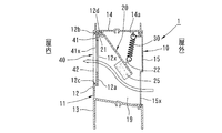
- the ventilation device 1 includes a device main body 10 and an operation plate 20 which extend horizontally and linearly.
- the longitudinal middle portion of the ventilation device 1 is omitted, and the ventilation device 1 is shown shorter than it actually is.
- the apparatus main body 10 is composed of two extrusion mold members 11 and 15.
- the mold 11 has an indoor side vertical portion 12, a lower connection portion 13, and an upper connection portion 14.
- the upper part of the indoor-side vertical part 12 of the mold 11 is retracted to the outdoor side from the lower part, and is provided as a main wall 12a.
- a large number of vertically elongated ventilating openings 12x are formed at equal intervals in the longitudinal direction.
- the indoor side vertical portion 12 is provided with engaging grooves 12b and 12c adjacent to the upper and lower edges of the main wall 12a and positioned on the indoor side of the main wall 12a.
- the role of the engagement grooves 12b and 12c will be described later.
- An axial support 12 d is formed at the intersection of the main wall 12 a and the upper connecting portion 14.
- the pivotal support portion 12d is adjacent to the main wall 12a on the outdoor side of the main wall 12a, and is located above the ventilation port 12x. The role of the shaft support 12d will be described later.
- the lower connecting portion 13 is formed in an inverted U shape and has a pair of ribs projecting downward.
- the upper edge of a glass plate (not shown) is fitted between the pair of ribs.
- the upper connecting portion 14 has a pair of ribs projecting upward, and the pair of ribs are inserted into the upper collar (not shown) of the sash door.
- the ventilator 1 is incorporated into the sash door.
- the mold material 15 has a plate-like shape and is provided as an outdoor side vertical portion.
- the upper and lower edges of the mold 15 are connected to the outer side edges of the lower connecting portion 13 and the upper connecting portion 14 of the mold 11.
- a large number of vertically elongated ventilating openings 15x are formed at equal intervals in the longitudinal direction.
- the device body 10 is hollow, and its internal space is provided as a ventilation passage 19.
- the ventilation passage 19 is connected indoors via a ventilation port 12x and is connected outdoors via a ventilation port 15x.
- the actuating plate 20 is also made of an extruded material, and has an axial portion 21 with a circular cross section at the upper edge.
- the actuating plate 20 is supported so as to move away from, approach to, or rotate with respect to the main wall 12 a of the device body 10.
- a packing 25 is attached to the surface of the lower portion of the actuating plate 20 (a part away from the shaft 21 serving as the pivot) facing the main wall 12a.
- the packing 25 extends along the working plate 20 along its entire length and has a uniform thickness.
- the packing 25 is made of a foamed resin (for example, urethane foam) having an open cell structure, and has air permeability and elasticity in the thickness direction (cushioning property).
- a foamed resin for example, urethane foam
- one having a density of 20 to 40 kg / m 3 and commercially available as a filter can be used.
- a product (MF-13) manufactured by INOAC can be used.
- the actuating plate 20 is maintained at a position (open position) away from the main wall 12a against its own weight by a plurality of tension coil springs 30 (springs) arranged at intervals in the longitudinal direction of the actuating plate 20. ing.
- One end of the coil spring 30 is hooked on a spring hooking portion 22 projecting outward from the lower part of the operation plate 20, and the other end is hooked on a spring hooking portion 14a formed on the upper connecting portion 14.
- Another working plate 41 made of an extrusion material is in contact with the surface of the main wall 12a on the indoor side.
- the actuating plate 41 has its upper and lower edges engaged with the engaging grooves 12b and 12c of the device body 10, and is thus slidably supported in the device body 10 in the longitudinal direction.
- a large number of ventilation openings 41x having the same shape as the ventilation openings 12x of the main wall 12a are formed in the operation plate 41 at the same pitch.
- a support plate 42 is attached to the right end of the apparatus main body 10.
- the support plate 42 is disposed on the indoor side of the operation plate 41, and is fixed in a state in which the upper and lower edges thereof are engaged with the engagement grooves 12b and 12c.
- An operation knob 43 is slidably supported by the support plate 42 in the longitudinal direction (left and right direction) of the apparatus main body 10.
- the operation knob 43 is connected to the operation plate 41, and by operating the operation knob 43, the operation plate 41 has an open position where the ventilation port 41x matches the ventilation port 12x of the main wall 12a, and the ventilation port 41x slides between vent 12x and a closed position not coincident with it.
- the operating plate 41, the support plate 42, and the operation knob 43 constitute an open / close mechanism 40.
- the ventilation port 41x is disposed below the ventilation port 12x, the air flows obliquely upward in the ventilation passage 19 as shown by the arrow in FIG. Since the actuating plate 20 is inclined along the flow of air, and the lower edge thereof is at substantially the same height as the upper end of the ventilation port 15x, only a part of the wind pressure acts on the actuating plate 20. Is pivoted in the closing direction against the spring 30, but is maintained in the open state.
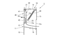
- the actuating plate 20 When the actuating plate 20 is closed as shown in FIG. 3, the actuating plate 20 covers the vent hole 12x, and the packing 25 is in contact with the main wall 12a over the entire length thereof while being sandwiched between the actuating plate 20 and the main wall 12a.
- the packing 25 is made of a foamed resin having an open cell structure and has air permeability, air flows into the inside of the packing 25 through the inside of the packing 25 as shown by an arrow in FIG. Therefore, the indoor environment can be maintained well.
- a manual opening / closing mechanism 40 is provided in addition to the operation plate 20 which opens / closes in accordance with the intensity of the wind outside the room.
- the operation plate 41 By operating the operation knob 43, the operation plate 41 can be slid between the open position where the ventilation port 41x matches the ventilation port 12x of the main wall 12a and the closed position not matching the main wall 12a. You can adjust the opening degree. As a result, when performing cooling or heating, the amount of air flow can be reduced to zero or small, and the efficiency of cooling and heating can be increased.
- the packing 25 of the first embodiment has a uniform thickness over the entire length
- the packing 25A shown in FIG. 5 may be used instead of the packing 25.
- the packing 25A has a shape in which the surface facing the main wall 12a repeats unevenness in the longitudinal direction. That is, a plurality of convex portions 25a extending in a direction orthogonal to the longitudinal direction are formed at equal intervals in the longitudinal direction, and a valley portion 25b is formed between the convex portions 25a.
- the convex portion 25a contacts the main wall 12a at the minimum wind pressure at which the operation plate 20 is in the closed position, and a large number of air passages are formed between the recess 25b and the main wall 12a. Ru. Therefore, the inflowing air amount can be alleviated from being sharply reduced compared to when the actuating plate 20 is in the open position.
- the ventilation device 2 of the second embodiment shown in FIGS. 7 to 9 is installed on the wall of a building. Briefly, on the wall of a building, a support frame 4 supporting the glass plate 3 on the upper floor, a support frame 6 supporting the glass plate 5 on the lower floor, and an indoor side support connected to the support frame 6 A frame 7 is provided. A ventilation passage 8 is formed between the support frame 4 and the support frames 6 and 7.
- the ventilation passage 8 includes the ventilating device 2 bridged by the support frames 4 and 7, and a lid member 9 (opening and closing mechanism) bridged by the support frames 4 and 7 above the ventilating device 2. Is arranged. With the lid 9 removed, ventilation through the ventilator 2 is performed.
- the support frames 4, 6, 7 and the ventilator 2 and the lid member 9 extend in the horizontal direction, that is, in the direction orthogonal to the paper surface in the figure.
- the ventilating apparatus 2 includes an apparatus body 50 and an operating plate 60.
- the apparatus body 50 has a horizontally extending extrusion 51 and a number of U-shaped brackets 55 fixed to the shape 51 at equal intervals in the longitudinal direction.
- the mold member 51 has a horizontal plate-like main wall 52, and the main wall 52 is formed with a large number of ventilation openings 52x at equal intervals in the longitudinal direction.
- a pivot support portion 53 is formed adjacent to the main wall 52 on the lower side (outdoor side) of the main wall 52.
- the actuating plate 60 is disposed below the main wall 52, and the shaft portion 61 is rotatably supported by being fitted into the pivotal support portion 53.
- An air-permeable packing 65 similar to the packing 25 of the first embodiment is attached to the upper surface (the surface facing the main wall 52) of a portion of the actuating plate 60 apart from the shaft 61 over the entire length of the actuating plate 60. ing.
- the ventilation device 2 urges the mat 70 provided on the bracket 55, the tension coil spring 71 urging the actuating plate 60 downward, that is, the opening direction, the hinge 72, and the actuating plate 60 in the closing direction.
- an extension member 74 formed of a leaf spring. One end of the coil spring 71 is hooked on the bracket 55, and the other end is hooked on the operation plate 60.
- the hinge 72 has two attachment pieces 72a and 72b, and a shaft 72c rotatably connecting the attachment pieces 72a and 72b to each other.
- the mounting piece 72a is fixed to the bracket 55, and the extension member 74 is fixed to the mounting piece 72b.
- the torsion spring 73 is wound around the shaft 72c and acts to spread the attachment pieces 72a and 72b.
- the tip of the extension member 74 is in contact with the actuating plate 60, and the force of the torsion spring 73 is applied to the actuating plate 60 via the extension member 74.
- the actuating plate 60 when there is no wind or weak, the actuating plate 60 is in the open position against the mat 70 by its own weight and the force in the opening direction by the coil spring 71, as shown in FIG. Since the force in the closing direction by the torsion spring 73 also acts on the actuating plate 60, the force in the opening direction of the actuating plate 60 can be weakened, and the closing operation can be smoothly performed when the wind is strengthened.
- the actuating plate 60 When the wind gets stronger, the actuating plate 60 reaches the closed position as shown in FIG. 9 and the vent hole 52x is covered by the actuating plate 60, but the inflow of air passes through the air-permeable packing 65 as shown by the arrow. It is possible.
- the actions of the actuating plate 60 and the packing 65 in the second embodiment are the same as those in the first embodiment, and thus detailed description will be omitted.
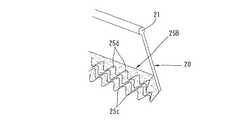
- packings 25A and 25B having the shapes shown in FIGS. 5 and 6 may be used.
- the present invention is not limited to the above embodiment, and various aspects can be adopted.
- the packings 25 and 65 used in the first and second embodiments are not particularly limited as long as they have elasticity and air permeability, and may be non-woven fabric made of fibers or the like.
- the packings 25A and 25B having the shapes shown in FIGS. 5 and 6 are used, the packings 25A and 25B may be made of a non-air-permeable material.
- the packing may be provided on the main wall, or may be provided on both the actuating plate and the opposite surface of the main wall.
- the opening and closing mechanism used in the first embodiment may be electrically operated instead of manual operation, or the operating plate may be automatically opened and closed depending on temperature using a coil spring made of shape memory alloy.
- the invention is also applicable to other types of ventilators, for example ventilators with a single vent.
- the present invention can be applied to a ventilation system that can be closed in strong winds.
Landscapes
- Engineering & Computer Science (AREA)
- Chemical & Material Sciences (AREA)
- Combustion & Propulsion (AREA)
- Mechanical Engineering (AREA)
- General Engineering & Computer Science (AREA)
- Ventilation (AREA)
- Air-Flow Control Members (AREA)
- Specific Sealing Or Ventilating Devices For Doors And Windows (AREA)
Abstract
Priority Applications (5)
| Application Number | Priority Date | Filing Date | Title |
|---|---|---|---|
| PCT/JP2014/066809 WO2015198416A1 (fr) | 2014-06-25 | 2014-06-25 | Dispositif de ventilation |
| CN201480024712.5A CN105393059A (zh) | 2014-06-25 | 2014-06-25 | 通风装置 |
| JP2016528803A JP6324505B2 (ja) | 2014-06-25 | 2014-06-25 | 換気装置 |
| KR1020157026149A KR20160015196A (ko) | 2014-06-25 | 2014-06-25 | 환기 장치 |
| AU2014391444A AU2014391444A1 (en) | 2014-06-25 | 2014-06-25 | Ventilation device |
Applications Claiming Priority (1)
| Application Number | Priority Date | Filing Date | Title |
|---|---|---|---|
| PCT/JP2014/066809 WO2015198416A1 (fr) | 2014-06-25 | 2014-06-25 | Dispositif de ventilation |
Publications (1)
| Publication Number | Publication Date |
|---|---|
| WO2015198416A1 true WO2015198416A1 (fr) | 2015-12-30 |
Family
ID=54937549
Family Applications (1)
| Application Number | Title | Priority Date | Filing Date |
|---|---|---|---|
| PCT/JP2014/066809 Ceased WO2015198416A1 (fr) | 2014-06-25 | 2014-06-25 | Dispositif de ventilation |
Country Status (5)
| Country | Link |
|---|---|
| JP (1) | JP6324505B2 (fr) |
| KR (1) | KR20160015196A (fr) |
| CN (1) | CN105393059A (fr) |
| AU (1) | AU2014391444A1 (fr) |
| WO (1) | WO2015198416A1 (fr) |
Cited By (9)
| Publication number | Priority date | Publication date | Assignee | Title |
|---|---|---|---|---|
| TWI669442B (zh) * | 2017-03-22 | 2019-08-21 | 日商Ykk建築製造股份有限公司 | Ventilation device and door and window |
| CN110578453A (zh) * | 2018-06-07 | 2019-12-17 | 周一珺 | 透明透气防风防雨防蚊蝇复合窗 |
| JP2021036121A (ja) * | 2019-08-26 | 2021-03-04 | 株式会社佐原 | 換気装置 |
| CN112665041A (zh) * | 2020-12-30 | 2021-04-16 | 刘磊 | 一种避免灰尘堵塞过滤网的中央空调 |
| CN113899043A (zh) * | 2021-11-03 | 2022-01-07 | 中国船舶重工集团公司第七一九研究所 | 一种用于集防系统的风门装置和集防系统 |
| CN114167956A (zh) * | 2021-12-09 | 2022-03-11 | 研华科技(中国)有限公司 | 一种嵌入式一体化工控机 |
| WO2022086017A1 (fr) * | 2020-10-23 | 2022-04-28 | (주)엘엑스하우시스 | Protection extérieure contre l'eau de pluie moulée par injection pour dispositif de ventilation de type pour fenêtre et porte |
| CN114737868A (zh) * | 2022-04-06 | 2022-07-12 | 浙江海博门业有限公司 | 一种具有透风除湿功能景观居室门 |
| JP2024061119A (ja) * | 2022-10-21 | 2024-05-07 | 株式会社佐原 | 換気装置 |
Families Citing this family (4)
| Publication number | Priority date | Publication date | Assignee | Title |
|---|---|---|---|---|
| US20190174233A1 (en) * | 2017-04-21 | 2019-06-06 | Temco Japan Co., Ltd. | Bone conduction speaker unit |
| CN113357801B (zh) * | 2021-05-17 | 2022-07-15 | 青岛海尔空调器有限总公司 | 进风结构、新风装置及空调 |
| CN113357811B (zh) * | 2021-05-17 | 2022-07-19 | 青岛海尔空调器有限总公司 | 进风结构、新风装置及空调 |
| CN113202262B (zh) * | 2021-05-25 | 2022-09-09 | 浙江宁溢电力工程设计咨询有限公司 | 一种地下变电所的通风装置 |
Citations (4)
| Publication number | Priority date | Publication date | Assignee | Title |
|---|---|---|---|---|
| JPS57185891U (fr) * | 1981-05-22 | 1982-11-25 | ||
| JPH0486889U (fr) * | 1990-11-30 | 1992-07-28 | ||
| JPH10220118A (ja) * | 1997-01-31 | 1998-08-18 | Juken Sangyo Co Ltd | 換気機能のあるドア枠材 |
| JP2006152625A (ja) * | 2004-11-26 | 2006-06-15 | Sekisui Chem Co Ltd | ドア構造 |
Family Cites Families (10)
| Publication number | Priority date | Publication date | Assignee | Title |
|---|---|---|---|---|
| JPS62147245A (ja) * | 1985-12-20 | 1987-07-01 | Keiichi Yasukawa | 構造物内の換気の方法 |
| JP2894424B2 (ja) * | 1994-02-25 | 1999-05-24 | 三菱電機株式会社 | 通風調節装置 |
| CN2303198Y (zh) * | 1997-03-18 | 1999-01-06 | 广东美的集团股份有限公司 | 分体落地式空调器 |
| JPH11190542A (ja) * | 1997-12-26 | 1999-07-13 | Natl House Ind Co Ltd | 住宅の換気システム |
| JP2002089914A (ja) * | 2000-09-18 | 2002-03-27 | Risutemu Kk | 定風量換気装置 |
| JP2003336360A (ja) * | 2002-05-20 | 2003-11-28 | Asahi Kasei Corp | 天窓構造 |
| CN2639488Y (zh) * | 2003-08-04 | 2004-09-08 | 吴湘瓯 | 可全开式窗 |
| JP4101775B2 (ja) | 2004-02-16 | 2008-06-18 | 株式会社佐原 | 換気装置のフィルタ取付構造 |
| JP5393202B2 (ja) | 2009-03-05 | 2014-01-22 | 株式会社豊和 | 換気装置 |
| CN202166140U (zh) * | 2011-07-22 | 2012-03-14 | 陈妙生 | 带有防火阀门的建筑通风器 |
-
2014
- 2014-06-25 WO PCT/JP2014/066809 patent/WO2015198416A1/fr not_active Ceased
- 2014-06-25 JP JP2016528803A patent/JP6324505B2/ja active Active
- 2014-06-25 KR KR1020157026149A patent/KR20160015196A/ko not_active Ceased
- 2014-06-25 AU AU2014391444A patent/AU2014391444A1/en not_active Abandoned
- 2014-06-25 CN CN201480024712.5A patent/CN105393059A/zh active Pending
Patent Citations (4)
| Publication number | Priority date | Publication date | Assignee | Title |
|---|---|---|---|---|
| JPS57185891U (fr) * | 1981-05-22 | 1982-11-25 | ||
| JPH0486889U (fr) * | 1990-11-30 | 1992-07-28 | ||
| JPH10220118A (ja) * | 1997-01-31 | 1998-08-18 | Juken Sangyo Co Ltd | 換気機能のあるドア枠材 |
| JP2006152625A (ja) * | 2004-11-26 | 2006-06-15 | Sekisui Chem Co Ltd | ドア構造 |
Cited By (17)
| Publication number | Priority date | Publication date | Assignee | Title |
|---|---|---|---|---|
| TWI669442B (zh) * | 2017-03-22 | 2019-08-21 | 日商Ykk建築製造股份有限公司 | Ventilation device and door and window |
| CN110578453A (zh) * | 2018-06-07 | 2019-12-17 | 周一珺 | 透明透气防风防雨防蚊蝇复合窗 |
| CN112443255B (zh) * | 2019-08-26 | 2023-02-17 | 株式会社佐原 | 换气装置 |
| JP2021036121A (ja) * | 2019-08-26 | 2021-03-04 | 株式会社佐原 | 換気装置 |
| KR20210024972A (ko) | 2019-08-26 | 2021-03-08 | 가부시키가이샤 사하라 | 환기 장치 |
| JP7390020B2 (ja) | 2019-08-26 | 2023-12-01 | 株式会社佐原 | 換気装置 |
| AU2020223654B2 (en) * | 2019-08-26 | 2021-07-01 | Sahara Co., Ltd. | Ventilation device |
| CN112443255A (zh) * | 2019-08-26 | 2021-03-05 | 株式会社佐原 | 换气装置 |
| WO2022086017A1 (fr) * | 2020-10-23 | 2022-04-28 | (주)엘엑스하우시스 | Protection extérieure contre l'eau de pluie moulée par injection pour dispositif de ventilation de type pour fenêtre et porte |
| CN112665041B (zh) * | 2020-12-30 | 2022-06-24 | 湖州泰益智能科技有限公司 | 一种避免灰尘堵塞过滤网的中央空调 |
| CN112665041A (zh) * | 2020-12-30 | 2021-04-16 | 刘磊 | 一种避免灰尘堵塞过滤网的中央空调 |
| CN113899043A (zh) * | 2021-11-03 | 2022-01-07 | 中国船舶重工集团公司第七一九研究所 | 一种用于集防系统的风门装置和集防系统 |
| CN114167956A (zh) * | 2021-12-09 | 2022-03-11 | 研华科技(中国)有限公司 | 一种嵌入式一体化工控机 |
| CN114737868A (zh) * | 2022-04-06 | 2022-07-12 | 浙江海博门业有限公司 | 一种具有透风除湿功能景观居室门 |
| CN114737868B (zh) * | 2022-04-06 | 2023-08-22 | 浙江海博门业有限公司 | 一种具有透风除湿功能景观居室门 |
| JP2024061119A (ja) * | 2022-10-21 | 2024-05-07 | 株式会社佐原 | 換気装置 |
| JP7875598B2 (ja) | 2022-10-21 | 2026-06-18 | 株式会社佐原 | 換気装置 |
Also Published As
| Publication number | Publication date |
|---|---|
| AU2014391444A1 (en) | 2016-01-21 |
| KR20160015196A (ko) | 2016-02-12 |
| JPWO2015198416A1 (ja) | 2017-04-20 |
| JP6324505B2 (ja) | 2018-05-16 |
| CN105393059A (zh) | 2016-03-09 |
Similar Documents
| Publication | Publication Date | Title |
|---|---|---|
| JP6324505B2 (ja) | 換気装置 | |
| JP2014522955A (ja) | 換気装置 | |
| WO2013128658A1 (fr) | Double fenêtre | |
| KR101763671B1 (ko) | 콤팩트한 구성이 가능한 차량 공기조화용 풍향조절장치 | |
| JP6342072B2 (ja) | 換気装置 | |
| KR200436719Y1 (ko) | 창틀용 통풍장치 | |
| JP2011226702A (ja) | 自然給気ユニット | |
| EP3064844B1 (fr) | Appareil de ventilation | |
| JP6375182B2 (ja) | 建具 | |
| JP6839009B2 (ja) | 換気装置及び建具 | |
| KR20090067535A (ko) | 공조장치 및 공조장치의 제어방법 | |
| KR101114886B1 (ko) | 창호용 통풍 환기장치 | |
| JP4035454B2 (ja) | 換気装置 | |
| JP3983181B2 (ja) | 換気装置 | |
| JP5463379B2 (ja) | 換気装置 | |
| JP6076066B2 (ja) | ドア | |
| CN209689030U (zh) | 空调室内机和具有其的空调器 | |
| KR100917264B1 (ko) | 환기장치 | |
| KR20090067344A (ko) | 카세트형 공기조화기의 필터가이드 | |
| JP6557059B2 (ja) | 自然換気装置 | |
| JP6839008B2 (ja) | 換気装置及び建具 | |
| KR200496230Y1 (ko) | 차량용 환풍장치 | |
| CN214576627U (zh) | 一种加强隔音与保温功能的百叶透气门 | |
| JP2010060198A (ja) | 調湿ルーバー | |
| JP2016135953A (ja) | 戸 |
Legal Events
| Date | Code | Title | Description |
|---|---|---|---|
| WWE | Wipo information: entry into national phase |
Ref document number: 201480024712.5 Country of ref document: CN |
|
| ENP | Entry into the national phase |
Ref document number: 20157026149 Country of ref document: KR Kind code of ref document: A |
|
| WWE | Wipo information: entry into national phase |
Ref document number: 2014391444 Country of ref document: AU |
|
| 121 | Ep: the epo has been informed by wipo that ep was designated in this application |
Ref document number: 14895943 Country of ref document: EP Kind code of ref document: A1 |
|
| ENP | Entry into the national phase |
Ref document number: 2016528803 Country of ref document: JP Kind code of ref document: A |
|
| NENP | Non-entry into the national phase |
Ref country code: DE |
|
| 122 | Ep: pct application non-entry in european phase |
Ref document number: 14895943 Country of ref document: EP Kind code of ref document: A1 |