WO2015198629A1 - Dispositif mobile autonome - Google Patents
Dispositif mobile autonome Download PDFInfo
- Publication number
- WO2015198629A1 WO2015198629A1 PCT/JP2015/054669 JP2015054669W WO2015198629A1 WO 2015198629 A1 WO2015198629 A1 WO 2015198629A1 JP 2015054669 W JP2015054669 W JP 2015054669W WO 2015198629 A1 WO2015198629 A1 WO 2015198629A1
- Authority
- WO
- WIPO (PCT)
- Prior art keywords
- autonomous mobile
- bumper
- mobile robot
- mobile device
- action
- Prior art date
- Legal status (The legal status is an assumption and is not a legal conclusion. Google has not performed a legal analysis and makes no representation as to the accuracy of the status listed.)
- Ceased
Links
Images






Classifications
-
- G—PHYSICS
- G05—CONTROLLING; REGULATING
- G05D—SYSTEMS FOR CONTROLLING OR REGULATING NON-ELECTRIC VARIABLES
- G05D1/00—Control of position, course, altitude or attitude of land, water, air or space vehicles, e.g. using automatic pilots
- G05D1/02—Control of position or course in two dimensions
- G05D1/021—Control of position or course in two dimensions specially adapted to land vehicles
- G05D1/0227—Control of position or course in two dimensions specially adapted to land vehicles using mechanical sensing means, e.g. for sensing treated area
-
- A—HUMAN NECESSITIES
- A01—AGRICULTURE; FORESTRY; ANIMAL HUSBANDRY; HUNTING; TRAPPING; FISHING
- A01D—HARVESTING; MOWING
- A01D34/00—Mowers; Mowing apparatus of harvesters
- A01D34/01—Mowers; Mowing apparatus of harvesters characterised by features relating to the type of cutting apparatus
- A01D34/412—Mowers; Mowing apparatus of harvesters characterised by features relating to the type of cutting apparatus having rotating cutters
- A01D34/63—Mowers; Mowing apparatus of harvesters characterised by features relating to the type of cutting apparatus having rotating cutters having cutters rotating about a vertical axis
- A01D34/64—Mowers; Mowing apparatus of harvesters characterised by features relating to the type of cutting apparatus having rotating cutters having cutters rotating about a vertical axis mounted on a vehicle, e.g. a tractor, or drawn by an animal or a vehicle
-
- G—PHYSICS
- G05—CONTROLLING; REGULATING
- G05D—SYSTEMS FOR CONTROLLING OR REGULATING NON-ELECTRIC VARIABLES
- G05D1/00—Control of position, course, altitude or attitude of land, water, air or space vehicles, e.g. using automatic pilots
Definitions
- the present invention relates to an autonomous mobile device, and more particularly, to an autonomous mobile device having an auxiliary traction mode that reduces a burden when an operator pulls the autonomous mobile device.
- Patent Document 1 discloses a technique for controlling the propulsion direction of the self-propulsion device by pulling or loosening a line attached to the self-propulsion device.
- FIG. 11 is a top view (a) showing the configuration of the self-propulsion device 500 of Patent Document 1 and a view (b) showing the retractable line guidance system 600.
- the self-propelling device 500 includes a main body 504, wheels 506, 508, 510, 512, and a motor 520, and an operator 502 operates a line 524 extended from a housing 526 of the main body 504 with a handle 532.
- the self-propelling device 500 includes a line guide system 600 having a reel 604 that winds the line 524 and a tension mechanism 610.
- the line guidance system 600 includes a line extension monitoring device 618, an angle monitoring device 622, and a vertical angle monitoring device 624, and monitors the extension length, angle, and displacement of the line 524 fed out from the arm 612, and maintains the selected value.
- the self-propulsion device 500 is promoted as described above.
- Japanese Patent Publication Japanese Patent Laid-Open No. 2011-170853 (published on September 1, 2011)”
- the self-propulsion device 500 of Patent Document 1 needs to newly add a configuration for monitoring the extension length, angle, and displacement of the line 524 of the line guidance system 600, and has a problem of increasing costs.
- This invention is made in view of the said subject, The objective is to add the function which assists a worker's traction with respect to an autonomous mobile apparatus at low cost, and to reduce a worker's physical burden. is there.
- An autonomous mobile device of the present invention includes a main body base, a moving mechanism provided at a lower portion of the main body base, a bumper that covers at least a front edge of the main body base, and a bumper that is displaceably connected to the main body base.
- An autonomous mobile device including a displacement detection unit that detects a displacement of the actuator includes an action unit that acts on the bumper to be displaced, and has an auxiliary traction mode that changes a movement state in an action direction of the action unit. .
- the action part is detachably installed on the bumper, and when the action part is attached, it shifts to the auxiliary traction mode.
- the action part is accommodated in a bumper so that it can be deployed, and when the action part is deployed, it shifts to an auxiliary traction mode.
- the action unit includes a safety device that executes the auxiliary traction mode only while detecting the operation signal.
- the auxiliary traction mode is characterized in that the speed is changed so as to reduce the displacement of the bumper by the action portion.
- the action part is a string-like member that pulls the bumper.
- the string-like member of the action part is characterized by having elasticity.
- the action portion is a handle member that propels the bumper from the rear.
- the auxiliary traction mode is characterized in that the work area is set by acquiring position information during movement.
- a function of assisting the operator to pull the autonomous mobile device can be added at low cost, and the physical burden on the worker can be reduced.
- FIG. 1 shows a schematic configuration of an autonomous mobile device (hereinafter referred to as an autonomous mobile robot) according to a first embodiment of the present invention, where (a) is a side view and (b) is a top view.
- an autonomous mobile robot main constituent mechanisms / parts visible from the outside are indicated by solid lines, and main constituent mechanisms / parts included inside are indicated by broken lines.
- the autonomous mobile robot 110 includes a main body base 10, a front wheel 12, a rear wheel 13, a front wheel drive mechanism 14, a rear wheel drive mechanism 15, a control means 16, a bumper 20, and a displacement transmission means 30 that constitute a moving mechanism. Including.
- the autonomous mobile robot 110 can control the front wheel drive mechanism 14 for driving the front wheels 12 or the rear wheel drive mechanism 15 for driving the rear wheels 13 by the control means 16 to perform autonomous traveling such as forward movement, reverse movement, and turning. It has become. It is also possible to run either the front wheel 12 or the rear wheel 13 as one drive wheel, and in that case, it is not necessary to provide both the front wheel drive mechanism 14 and the rear wheel drive mechanism 15.
- a lawn mowing cutter 17 is provided at the bottom of the main body base 10.
- the lawn mowing cutter 17 rotates when the power of the cutter driving motor 18 is transmitted through the rotating shaft.
- the main body base 10 of the autonomous mobile robot 110 is provided with various mechanisms and components as described above.
- the bumper 20 is mainly formed of a resin or the like so as to have a substantially outer shape of the autonomous mobile robot 110, and is installed so as to be relatively displaceable in the XY direction with respect to the main body base 10 via the displacement transmission means 30. ing.
- the bumper 20 touches an obstacle such as an object or a person during autonomous movement, the bumper 20 detects the contact by displacing with respect to the main body base 10, and the autonomous mobile robot 110 is controlled via the control means 16. It functions as an york-garde mechanism that ensures safety at the time of contact, such as stopping and retreating.
- two displacement transmission means 30 are provided on the front side of the main body base 10 (30a, 30b) and two are provided on the rear side of the main body base 10 ( 30c, 30d), a total of four are provided.
- the displacement transmission means 30 changes in size and mounting height depending on whether it is installed on the front side or the rear side of the autonomous mobile robot 110, but the basic configuration and function are the same. is there.
- the displacement transmission means 30 is installed in the front side and back side of the autonomous mobile robot 110, it is not restricted to this, Only the front side or only the back side may be sufficient. Alternatively, a configuration in which three in total, one at the front center and two at the left and right at the rear, may be installed.
- the autonomous mobile robot 110 can attach the action part 40 to the bumper 20 via the attachment part 22.
- the action part 40 is, for example, a string-like member such as elastic rubber.
- the attachment portion 22 is a pull-out hook, and can be pulled out by hand from the state of being housed in the bumper 20, and is brought into a housed state when pushed in from the state of being pulled out.
- the base of the attachment portion 22 is provided with a drawer detection portion 23 that detects whether or not the attachment portion 22 has been pulled out.
- the drawer detection unit 23 is a general micro switch.
- the autonomous mobile robot 110 of the present invention has a first movement mode in which it moves autonomously by a work such as lawn mowing, and a second mode in which it is pulled by an operator, a bicycle, a car, etc. There are several movement modes.
- the autonomous mobile robot 110 moves autonomously while driving the lawn mowing cutter 17 and performs work such as lawn mowing.
- the autonomous mobile robot 110 detects the state of the attachment portion 22 with the drawer detection portion 23 and switches the movement mode. Specifically, the autonomous mobile robot 110 enters the first movement mode when the attachment portion 22 is in the retracted state, and enters the second movement mode when the attachment portion 22 is pulled out and the action portion 40 is attached. Are switched as follows.
- the action unit 40 is used when an operator, a bicycle, a car, or the like pulls the autonomous mobile robot 110 when the autonomous mobile robot 110 is switched to the second movement mode.
- the action part 40 can be comprised with the member which can be pulled or pushed forward by an operator, a bicycle, a motor vehicle, etc. besides the string-like member mentioned above.
- the autonomous mobile robot 110 stops the lawn mowing cutter 17.
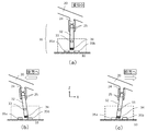
- FIGS. 2 and 3 are schematic schematic diagrams showing an interlocking state between the bumper 20 and the displacement transmitting means 30.
- FIG. 2 and 3 one of the displacement transmission means 30 a, 30 b, 30 c, and 30 d is described as a representative of the displacement transmission means 30.
- the interlocking between the bumper 20 and the displacement transmission means 30 will be described in detail with reference to FIGS.
- FIG. 2 is a side view of the connecting portion between the bumper 20 and the displacement transmission means 30.
- FIG. 2A shows a standard state before the bumper 20 is displaced
- FIG. 2B shows the bumper 20 displaced backward.
- (C) shows a state in which the bumper 20 is displaced forward.
- FIG. 3 is a top view showing the operation of the displacement transmitting means 30 corresponding to the displacement of the bumper 20, respectively.
- the bumper 20 has a protrusion 24 on the inner side in order to engage with the displacement transmission means 30.
- the protrusion 24 is arranged so as to be positioned at the center of the displacement transmitting means 30 and directly above when the bumper 20 is in the standard state (a).
- the displacement transmission means 30 has a stick portion 32 for engaging with the protrusion 24 of the bumper 20.
- the stick part 32 is connected to the protrusion part 24 by the connecting member 25 and receives the upper part of the stick part 32 via the rotation shaft 33 in order to receive the displacement of the protrusion part 24 based on the displacement of the bumper 20.
- the displacement is transmitted as a displacement in the opposite direction below the rotating shaft 33.
- the rotating shaft 33 is, for example, a spherical joint, and the joint base is fixed to the main body base 10.
- the rotating shaft 33 can be inclined in all the front, rear, left and right directions.
- the connecting member 25 is fixed to the protrusion 24 of the bumper 20 in advance, approaches the stick portion 32 side, and the stick portion 32 is fitted into the connecting member 25, so that the bumper 20 and the displacement transmitting means are connected. 30 are connected.
- the connecting member 25 is preferably composed of an elastic member such as synthetic rubber so that the stick portion 32 can be smoothly inserted.
- At least one of the four displacement transmission means 30a to 30d includes a displacement detection structure (displacement detection unit) described later.
- the displacement detection structure includes a magnet 34 provided at the lower portion of the stick portion 32 and Hall elements 35a to 35d arranged in four directions with respect to the lower portion of the stick portion 32. ing.
- the magnet 34 below the stick portion 32 is in a neutral state at the center of the hall elements 35a to 35d, so that the displacement of the bumper 20 is not detected by the hall elements 35a to 35d. .
- the magnet 34 at the lower part of the stick portion 32 is brought close to the hall element 35b disposed in front of the main body base 10 (on the right side in the drawing), and the output of the hall element 35b changes. By doing so, it is detected that the bumper 20 is displaced rearward.
- the bumper 20 when the bumper 20 is relatively displaced to the left rear side (the left rear side in the drawing) of the main body base 10, as shown in FIG.
- the outputs of the hall element 35b and the hall element 35d change in the vicinity of the hall element 35b and the hall element 35d arranged on the right front side, it is detected that the bumper 20 is displaced to the left rear.
- the bumper 20 when the bumper 20 is relatively displaced to the right rear or right front of the main body base 10, the displacement and direction of the bumper 20 are detected by changing the outputs of the corresponding hall elements 35a to 35d as described above. can do.
- the outputs of these Hall elements 35a to 35d are transmitted to the control means 16, and the autonomous mobile robot 110 can recognize the displacement of the bumper 20.
- the Hall element 35 can be replaced with a non-contact type switch such as a photo interrupter or an electrical contact type switch.
- the magnet 34 and the Hall elements 35a to 35d constituting the displacement detection structure may be mounted on only one of the displacement transmission means 30a to 30d. It is also possible to mount it on.
- the Hall elements 35a of the plurality of displacement transmitting means 30a to 30d are integrated by OR operation and determined as one detection state. The remaining Hall elements 35b to 35d are similarly processed.
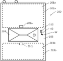
- FIG. 4 shows an embodiment in which the autonomous mobile robot 110 of the present invention is applied to a lawn mowing robot.
- the auxiliary traction operation that is the second movement mode in the autonomous mobile robot 110 of the present invention will be described.
- a first lawn mowing area 201a is set in the front yard and a second lawn mowing area 201b is set in the back yard across the building 204 in the site 200.
- These lawn mowing areas 201 are areas in which turf is planted, and are work areas in which the autonomous mobile robot 110 performs lawn mowing while moving autonomously by applying the first movement mode.
- the autonomous mobile robot 110 can recognize the lawn mowing area 201 as a work area.
- the autonomous mobile robot can detect the magnetic field and the lawn mowing area.
- region 201 may be another method.
- the autonomous mobile robot 110 In the first movement mode, the autonomous mobile robot 110 is configured not to travel and drive the cutter in a place where the wire current cannot be detected. On the other hand, in the second movement mode, the autonomous mobile robot 110 is configured to be able to travel by auxiliary traction even in a place where the wire current cannot be detected.
- a first lawn mowing area 201a is set by laying a first wire 203a from a first charging station 202a installed in a front yard.
- a current flows from the first charging station 202a to the first wire 203a, and the autonomous mobile robot 110 detects the magnetic field, thereby recognizing where the first lawn mowing region 201a is located (region information). To do.
- the second charging station 202b and the second wire 203b are laid to recognize the second lawn mowing area 201b.
- the conventional lawn mowing robot recognizes the first lawn mowing area 201a and the second lawn mowing area 201b by the above method and mows the lawn while moving autonomously.
- the lawn mowing robot is moved outside the work area recognition, such as the passage 205 leading from the front yard to the back yard, the worker W has moved by carrying the lawn mowing robot.
- the lawn mowing robot is heavy, a great amount of labor is required for the operator W to carry it.
- a safe and appropriate route such as an auxiliary traction of the operator W can be provided even in a place such as the passage 205 where the lawn is not planted, while the driving mechanism of the autonomous mobile robot 110 provides the driving force for movement. Is moved to the next lawn mowing area 201.
- the autonomous mobile robot 110 when the lawn mowing work in the first lawn mowing area 201a is completed and it is desired to move to the next second lawn mowing area 201b, the operator W moves to the autonomous mobile robot 110.
- the attachment part 22 is pulled out and the action part 40 is attached to switch the operation mode of the autonomous mobile robot 110 to the auxiliary traction operation, that is, the second movement mode.
- the worker W assists and pulls the autonomous mobile robot 110 by the action unit 40, so that the autonomous mobile robot 110 tracks the worker W by following the assistant tow while using its own driving force. Accordingly, when the worker W moves along the predetermined route of the passage 205 while auxiliary towing the autonomous mobile robot 110, the autonomous mobile robot 110 moves autonomously by tracking the trajectory of the worker W substantially. .
- the worker W does not need the labor to carry by using the driving force of the autonomous mobile robot 110, and the autonomous mobile robot 110 operates despite the autonomous mobile robot 110 being operated outside the work area recognition. However, the worker W can be tracked without deviating from the route without permission.
- the auxiliary traction does not mean that the worker W is towed while the autonomous mobile robot 110 is stopped and is heavy, but is an operation using the driving force of the autonomous mobile robot 110. W has almost no physical burden, and is used for the purpose of towing with the assistance of auxiliary speed adjustment and direction change.
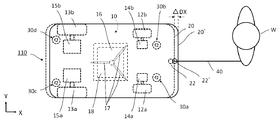
- FIG. 5 is a top view showing a state where the worker W is auxiliary towing the autonomous mobile robot 110 by the action unit 40.
- a tracking method for the worker W when the autonomous mobile robot 110 is operated in an auxiliary traction operation (second movement mode) will be described with reference to FIG.
- a figure indicated by a dotted line indicates a standard state
- a solid line 20 ′ and a solid line 22 ′ indicate the displacement state of the bumper 20 and the mounting portion 22.
- the autonomous mobile robot 110 When the worker W switches the operation mode of the autonomous mobile robot 110 to the auxiliary traction operation (second movement mode), the autonomous mobile robot 110 temporarily stops traveling. When the operator W assists and pulls the action unit 40 in the second movement mode, the autonomous mobile robot 110 starts operating at a predetermined operation speed.
- the predetermined operation speed is set to be approximately the same as the walking speed of a general pedestrian, for example.
- the operation speed may decrease with respect to the set speed due to the shape of the ground, the wet condition, the inclination / undulation condition, and obstacles such as stone rollers.
- the bumper 20 of the autonomous mobile robot 110 is pulled by the auxiliary traction of the operator W as shown in FIG. ( ⁇ DX) occurs.
- the protrusion 24 of the bumper 20 is similarly displaced in the right side of the drawing.
- the magnet 34 provided at the lower portion of the stick portion 32 is arranged behind the main body base 10 (on the left side in the drawing). It is detected that the bumper 20 is displaced forward by changing the output of the Hall element 35a in the vicinity of the Hall element 35a.
- the autonomous mobile robot 110 recognizes that the operation is delayed backward relative to the worker W, and issues a speed increase command from the control means 16 to the front wheel drive mechanism 14 or the rear wheel drive mechanism 15.
- the command to increase the speed depends on the delay situation, but continues until the bumper is displaced due to the increased speed. Specifically, the increase in speed is stopped when the magnet 34 of the displacement transmitting means 30 does not overlap any of the Hall elements 35 and the displacement transmitting means 30 is in the standard state. If the speed increase is not sufficient with one command and the bumper 20 seems to be displaced again, the control means 16 transmits the speed increase command again.
- the speed since it is not safe for the speed to continue to increase, it is programmed to gradually decelerate after increasing to a preset speed in the second movement mode. As a result of the deceleration, the Hall element 35a is turned on again when the action part 40 is pulled forward, and the control means 16 sends a command to increase the speed again.
- the autonomous mobile robot 110 can track the trajectory of the worker W while keeping the distance from the worker W constant under the auxiliary traction operation, that is, the second movement mode. Since the action part 40 is a string-like member such as elastic rubber, the displacement of the speed fluctuation transmitted to the operator W's hand is mitigated, and the operator W can perform towing without feeling a burden.
- FIG. 6 is a top view showing a state where the worker W is auxiliary towing the autonomous mobile robot 110 by the action unit 40.
- a figure indicated by a dotted line indicates a standard state
- a solid line 20 ′ and a solid line 22 ′ indicate the displacement state of the bumper 20 and the mounting portion 22.
- the axis C1 of the movement direction of the action unit 40 to which the worker W is auxiliary and the axis C2 of the movement direction of the autonomous mobile robot 110 are shown. This represents a case where the action unit 40 is in an auxiliary pulling state of the autonomous mobile robot 110 obliquely from the worker W.
- the bumper 20 of the autonomous mobile robot 110 is pulled by the action unit 40 by the auxiliary traction of the operator, so that the traveling direction (the X direction on the paper surface) A relative displacement occurs in the Y direction perpendicular to the traveling direction. That is, the displacement has both components of ⁇ DX and ⁇ DY.
- the stick portion 32 tilts around the rotation axis, and the magnet 34 moves in a direction having components in the ⁇ X direction and the ⁇ Y direction as shown in FIG. And it will be in the state detected by overlapping with both of the Hall elements 35d.
- the control means 16 recognizes that the bumper 20 is displaced to the front left side of the autonomous mobile robot 110 (upper right direction in the drawing) by obtaining both ON signals obtained from the Hall element 35a and the Hall element 35d. That is, it is recognized that the operation of the autonomous mobile robot 110 is delayed relative to the worker W in the right rear direction with respect to the traveling direction. Based on this recognition, the control means 16 issues the following trajectory correction command to the right drive wheel 13a and the left drive wheel 13b.
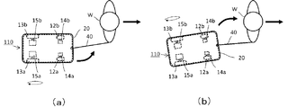
- FIGS. 7A and 7B show an embodiment of the trajectory correction of the autonomous mobile robot 110 for the state described above. Based on the recognition that the control means 16 of the autonomous mobile robot 110 is behind in the right rear direction relative to the worker W, first, as shown in FIG. Command to drive the left drive wheel 13b slightly later.
- the autonomous mobile robot 110 When the autonomous mobile robot 110 turns the rudder to the front left side, as shown in FIG. 7B, the direction in which the worker W can be seen from the autonomous mobile robot 110 changes from the left front to the front. When the displacement direction is the front, the autonomous mobile robot 110 drives the left and right drive wheels evenly. If it progresses in this state, the autonomous mobile robot 110 will eventually reach the left rear of the worker W. As a result, the autonomous mobile robot 110 is now pulled right forward. As described above, the autonomous mobile robot 110 swings left and right behind the worker W, but the amplitude gradually converges because it receives friction from the ground.
- the displacement ( ⁇ DY) is relatively higher than the main body base 10 on the upper side of the drawing.
- the magnet 34 moves in the -Y direction and overlaps with the Hall element 35d to be electrically detected.
- the control means 16 of the autonomous mobile robot 110 issues a command for moving the right driving wheel 13a forward and moving the left driving wheel 13b backward. As a result, the autonomous mobile robot 110 turns to the left.
- the bumper 20 of the autonomous mobile robot 110 is pulled in an obliquely rearward direction, for example, an obliquely backward leftward direction by the auxiliary traction of the worker W, it is relatively displaced ( ⁇ DX and ⁇ DY) are generated, and the magnet 34 moves in the + X and ⁇ Y directions and overlaps with the Hall element 35b and the Hall element 35d to be electrically detected.
- the control means 16 of the autonomous mobile robot 110 issues a command for causing the right drive wheel 13a to move backward slowly and the left drive wheel 13b to move backward quickly. As a result, the autonomous mobile robot 110 turns to the left while moving backward.
- the magnet 16 is also displaced in the + Y direction on the right side, and the Hall element 35c detects an overlap. To do.
- the vehicle moves while turning in the pulled direction with respect to the diagonally forward, lateral, and diagonally backward directions as viewed from the autonomous mobile robot 110.
- no driving force is generated in the rear direction. This is because the action part 40 and the attachment part 22 are configured to move with respect to the forward direction of the vehicle body, and traction to the rear is not suitable for use.
- the action unit 40 is a stretchable rubber string-like member.
- the action unit 40 may be constituted by a band, a metal or resin chain, a rod-shaped member, or the like.
- the speed is gradually reduced after increasing to a preset speed, but instead of speed control, the motor is simply rotated at a constant output at a lower speed than the expected walking speed. May be. Further, the motor may be in a brake state when stopped in the automatic mode, and the brake may be released when the action portion is pulled in the auxiliary traction mode.
- FIG. 8 shows an example of the autonomous mobile robot 120 according to the second embodiment of the present invention.
- FIG. 8 shows an application in a scene in which the autonomous mobile robot 120 is operated in the auxiliary traction mode (second operation mode) and a map of its own work area is created.
- a lawnmower robot composed of the autonomous mobile robot 120 is applied to a sports facility such as a golf course.
- the autonomous mobile robot 120 is used in the initial stage of work when setting a work area for actually cutting grass shown by a one-dot chain line in the predetermined area 230.
- the predetermined area 230 where the work is performed there are a tree stand 240, a pond 241 and the like, and this area is set in the autonomous mobile robot 120 so that there is no lawn and no mowing work is performed (this area is not entered). There is a need. In other words, it is necessary to set (Teaching) the autonomous mobile robot 120 so as to work the work area 231 indicated by the one-dot chain line to be worked.
- the autonomous mobile robot 120 is connected from the tail of the guide car 220 by the action part 42, and auxiliary traction is performed from the guide car 220 through the action part 42. At this time, the autonomous mobile robot 120 is equipped with the GPS 61 and stores the position coordinate data measured by the GPS 61 in the storage means 62 during auxiliary traction.
- auxiliary traction mode (second operation mode) by such auxiliary traction is used at the time of setting (Teaching) the work area (lawn mowing area). It's okay to operate.
- the technique of the present invention is applied, and the work area (mowing area) can be set (Teaching) again.
- the autonomous mobile robot 120 autonomously carries out work such as lawn mowing based on the work area 231 stored in the storage means 62 when it next operates and works in the autonomous movement mode (first operation mode). Can do.
- the technology of the present invention lays wires and the like as compared with conventional products in which an autonomous mobile robot senses a magnetic field and judges the work area by laying a wire etc. on the outer periphery of the work area and flowing current. Work / expense is unnecessary. In addition, it is not necessary to incorporate a special sensor for determining whether the area is the lawn area.
- the area setting of the autonomous mobile robot 120 is not limited to the currently available GPS, but can also be applied to future high-accuracy GPS, in which case the area setting accuracy and lawn mowing accuracy can be further improved. it can. Moreover, although the said embodiment was applied in facilities, such as a golf course, it is not restricted to this, You may apply to use in the garden of an individual's home.
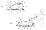
- FIG. 9 shows an autonomous mobile robot 130 according to the third embodiment of the present invention.
- the autonomous mobile robot 130 when the autonomous mobile robot 130 is operated in the auxiliary traction mode (second operation mode), the operator W moves from behind the autonomous mobile robot 130, contrary to the first and second embodiments.
- the utilization form pushed forward through the action part 44 is shown.
- the action unit 44 is a lever that is installed so as to be deployable, and is connected to the protrusion 24 on the rear side of the bumper 20 of the autonomous mobile robot 130 via a rotating shaft 51 for storage.
- the axial direction of the rotating shaft 51 is the left-right direction of the vehicle body, and the action portion 44 is housed in the upper portion of the vehicle body as shown in FIG.
- the action part 44 is deployed to the rear of the vehicle body as shown in FIG.
- a handle 52 is installed on the action part 44 so that the operator W can easily operate it.
- the protrusion 24 incorporates a deployment detection switch (not shown) in order to detect the deployed state of the action portion 44.
- the unfolding detection switch is turned on when the action part 44 is completely stored, and turned off when it is caused even a little.
- the rotation shaft 51 firmly connects the bumper 20 and the action portion 44 in directions other than the axis. When a force in the front and rear direction and the left and right direction of the action portion is applied, the bumper 20 Displaces left and right.
- the magnet 34 and the hall elements 35a to 35d constituting the displacement detection structure are built in either one or both of the front-side displacement transmission means 30a and 30b.
- the rear displacement transmitting means 30c, 30d may be displaced in the direction opposite to the traveling direction by the operating force of the operator W, and thus is not suitable for mounting a displacement detection structure. For example, when the operator W tries to advance the vehicle body to the left, the operator W pushes it forward while turning the handle counterclockwise.
- the autonomous mobile robot 130 enters the autonomous movement mode (first operation mode) when the deployment detection switch is ON, and shifts to the auxiliary traction mode (second operation mode) when the deployment detection switch is OFF. .
- the autonomous mobile robot 130 travels at a speed almost equal to that of the worker W while using the driving force generated from its own drive mechanism.
- the control means 16 via the displacement transmission means 30. Issues a command to the drive wheels to increase speed.
- the axis C1 of the movement direction of the action unit 44 propelled by the worker W and the axis C2 of the movement direction of the autonomous mobile robot 130 are shifted, and the autonomous mobile robot 130 7A and 7B, the driving force is driven alternately or stepwise to change the bumper 20 so that the displacement of the bumper 20 is eliminated, as described in FIGS. You just have to fix it.
- FIG. 10 shows an autonomous mobile robot 140 according to Embodiment 4 of the present invention.
- the autonomous mobile robot 140 according to the fourth embodiment is an example used when an AGV (Automated Guided Vehicle) is carried out of the track.
- FIG. 10A is a side view of the autonomous mobile robot 140 (AGV) according to the fourth embodiment, and FIG. 10B is a perspective view.
- AGV Automated Guided Vehicle
- the autonomous mobile robot 140 includes a main body base 11 and a bumper 21.
- the bumper 21 has a ring shape covering the entire circumference of the side surface, and is attached to the front side portion and the rear side portion of the main body base 11 via displacement transmitting means 31a, 31b, 31c, 31d.
- the bumper 21 includes an action portion 46 formed of a U-shaped handle member, and both ends of the action portion 46 are connected to the bumper 21.
- the action unit 46 includes a deadman switch 72 that functions as a safety device in the center of the handle 71.
- the main body base 11 is grounded by a drive wheel 77, a front universal wheel 78, and a rear universal wheel 79.
- the main body base 11 has a guide sensor 74 for detecting a magnetic tape track on the road surface at the lower part of the vehicle body.
- the main body base 11 has a mark sensor 75 for detecting a stop position installed on the road surface at the lower part of the vehicle body. If the mark sensor 75 detects a stop mark on the road surface while the autonomous mobile robot 140 is traveling in the autonomous movement mode, the traveling of the autonomous movement is stopped.
- the main body base 11 includes an LRF 73 for detecting an obstacle, detects an object or a person in front of the vehicle body, and measures a distance.
- the autonomous mobile robot 140 limits the speed when a measurement object is seen within a predetermined distance, decelerates within a deceleration distance, and stops within a stop distance.
- the auxiliary traction mode is set, and the speed restriction is released while the deadman switch 72 is grasped. While the autonomous mobile robot 140 is autonomously traveling on the track, even if the deadman switch 72 is gripped, the operation does not change and the speed limit is applied.
- the autonomous mobile robot 140 runs along a predetermined course along the magnetic tape track and stops at a predetermined stop point. Because the unloading place is crowded with workers who take out the load, the stop point is a little (several meters) next to the unloading place for safety.
- the worker W easily pulls the autonomous mobile robot 140 from the stop point to the unloading place by pulling in the auxiliary traction mode while pressing the deadman switch 72 of the action unit 46. It can be moved to the unloading place.
- the worker W unloads the load from the platform of the autonomous mobile robot 140 at the unloading place. After that, the auxiliary traction mode is used again to move to a predetermined stop point.
- the autonomous mobile robot 140 returns to the autonomous movement mode, starts the automatic course travel, and goes to the next stop point.
Landscapes
- Engineering & Computer Science (AREA)
- Aviation & Aerospace Engineering (AREA)
- Radar, Positioning & Navigation (AREA)
- Remote Sensing (AREA)
- Physics & Mathematics (AREA)
- General Physics & Mathematics (AREA)
- Automation & Control Theory (AREA)
- Life Sciences & Earth Sciences (AREA)
- Environmental Sciences (AREA)
- Control Of Position, Course, Altitude, Or Attitude Of Moving Bodies (AREA)
Abstract
L'objet de la présente invention consiste à ajouter à faibles coûts une fonction d'assistance de traction pour un travailleur à un dispositif mobile autonome, ce qui permet de réduire la charge du travailleur. La présente invention concerne un dispositif mobile autonome qui comprend une base de corps principal (10), un mécanisme en mouvement qui est disposé sur la partie inférieure de la base de corps principal, un pare-chocs (20) et une unité de détection de déplacement qui raccorde le pare-chocs à la base de corps principal d'une manière déplaçable et qui détecte le déplacement du pare-chocs, le dispositif mobile autonome étant équipé d'une partie de fonctionnement (40) destinée à agir sur et à déplacer le pare-chocs et comprenant un mode de traction assistée permettant de modifier l'état de mouvement du dispositif mobile autonome en fonction d'une direction d'action de la partie de fonctionnement.
Applications Claiming Priority (2)
| Application Number | Priority Date | Filing Date | Title |
|---|---|---|---|
| JP2014-130047 | 2014-06-25 | ||
| JP2014130047A JP5792361B1 (ja) | 2014-06-25 | 2014-06-25 | 自律移動装置 |
Publications (1)
| Publication Number | Publication Date |
|---|---|
| WO2015198629A1 true WO2015198629A1 (fr) | 2015-12-30 |
Family
ID=54346188
Family Applications (1)
| Application Number | Title | Priority Date | Filing Date |
|---|---|---|---|
| PCT/JP2015/054669 Ceased WO2015198629A1 (fr) | 2014-06-25 | 2015-02-19 | Dispositif mobile autonome |
Country Status (2)
| Country | Link |
|---|---|
| JP (1) | JP5792361B1 (fr) |
| WO (1) | WO2015198629A1 (fr) |
Cited By (3)
| Publication number | Priority date | Publication date | Assignee | Title |
|---|---|---|---|---|
| JP2018014963A (ja) * | 2016-07-29 | 2018-02-01 | 日立工機株式会社 | 自走式作業機 |
| JP2018190363A (ja) * | 2017-05-11 | 2018-11-29 | ボット3, インコーポレイテッドBot3, INC. | 携帯型移動ロボット及びその操作方法 |
| WO2021060254A1 (fr) * | 2019-09-27 | 2021-04-01 | 株式会社やまびこ | Machine de travail robotisée autonome |
Families Citing this family (4)
| Publication number | Priority date | Publication date | Assignee | Title |
|---|---|---|---|---|
| CN111201497A (zh) * | 2017-07-10 | 2020-05-26 | 旅伴机器人股份有限公司 | 自主机器人系统 |
| EP3833176B1 (fr) | 2018-08-08 | 2024-06-12 | The Toro Company | Navigation et entraînement de machine autonome faisant appel à un système de vision |
| JP7495154B2 (ja) * | 2020-06-15 | 2024-06-04 | 株式会社Doog | 自律移動装置、自律移動方法及びプログラム |
| SE2450418A1 (en) * | 2024-04-19 | 2024-12-04 | Husqvarna Ab | Installation guide |
Citations (9)
| Publication number | Priority date | Publication date | Assignee | Title |
|---|---|---|---|---|
| JPH0366504U (fr) * | 1989-10-25 | 1991-06-27 | ||
| JPH0556726U (ja) * | 1991-12-27 | 1993-07-27 | 北芝電機株式会社 | 電動カート |
| JPH08207850A (ja) * | 1995-02-03 | 1996-08-13 | Nikon Corp | 追従型制御装置 |
| JPH08282498A (ja) * | 1995-04-14 | 1996-10-29 | Matsushita Electric Works Ltd | パワーアシスト付運搬車 |
| JPH09150740A (ja) * | 1995-11-28 | 1997-06-10 | Kubota Corp | 電動手押し車 |
| JP2005339181A (ja) * | 2004-05-26 | 2005-12-08 | Matsushita Electric Works Ltd | 自律移動車 |
| JP2006290319A (ja) * | 2005-04-12 | 2006-10-26 | Kiyoshi Shimizu | 電動アシスト手押し台車 |
| JP2007052527A (ja) * | 2005-08-16 | 2007-03-01 | Matsushita Electric Ind Co Ltd | ロボット |
| WO2009050986A1 (fr) * | 2007-10-17 | 2009-04-23 | Kabushiki Kaisha Yaskawa Denki | Corps mobile |
-
2014
- 2014-06-25 JP JP2014130047A patent/JP5792361B1/ja not_active Expired - Fee Related
-
2015
- 2015-02-19 WO PCT/JP2015/054669 patent/WO2015198629A1/fr not_active Ceased
Patent Citations (9)
| Publication number | Priority date | Publication date | Assignee | Title |
|---|---|---|---|---|
| JPH0366504U (fr) * | 1989-10-25 | 1991-06-27 | ||
| JPH0556726U (ja) * | 1991-12-27 | 1993-07-27 | 北芝電機株式会社 | 電動カート |
| JPH08207850A (ja) * | 1995-02-03 | 1996-08-13 | Nikon Corp | 追従型制御装置 |
| JPH08282498A (ja) * | 1995-04-14 | 1996-10-29 | Matsushita Electric Works Ltd | パワーアシスト付運搬車 |
| JPH09150740A (ja) * | 1995-11-28 | 1997-06-10 | Kubota Corp | 電動手押し車 |
| JP2005339181A (ja) * | 2004-05-26 | 2005-12-08 | Matsushita Electric Works Ltd | 自律移動車 |
| JP2006290319A (ja) * | 2005-04-12 | 2006-10-26 | Kiyoshi Shimizu | 電動アシスト手押し台車 |
| JP2007052527A (ja) * | 2005-08-16 | 2007-03-01 | Matsushita Electric Ind Co Ltd | ロボット |
| WO2009050986A1 (fr) * | 2007-10-17 | 2009-04-23 | Kabushiki Kaisha Yaskawa Denki | Corps mobile |
Cited By (8)
| Publication number | Priority date | Publication date | Assignee | Title |
|---|---|---|---|---|
| JP2018014963A (ja) * | 2016-07-29 | 2018-02-01 | 日立工機株式会社 | 自走式作業機 |
| JP2018190363A (ja) * | 2017-05-11 | 2018-11-29 | ボット3, インコーポレイテッドBot3, INC. | 携帯型移動ロボット及びその操作方法 |
| WO2021060254A1 (fr) * | 2019-09-27 | 2021-04-01 | 株式会社やまびこ | Machine de travail robotisée autonome |
| JP2021052615A (ja) * | 2019-09-27 | 2021-04-08 | 株式会社やまびこ | 自動走行式のロボット作業機 |
| CN114521104A (zh) * | 2019-09-27 | 2022-05-20 | 株式会社山彦 | 自动移动式的机器人作业机 |
| JP7309559B2 (ja) | 2019-09-27 | 2023-07-18 | 株式会社やまびこ | 自動走行式のロボット作業機 |
| CN114521104B (zh) * | 2019-09-27 | 2024-01-30 | 株式会社山彦 | 自动移动式的机器人作业机 |
| US12342752B2 (en) | 2019-09-27 | 2025-07-01 | Yamabiko Corporation | Autonomous travel robotic working machine |
Also Published As
| Publication number | Publication date |
|---|---|
| JP2016009356A (ja) | 2016-01-18 |
| JP5792361B1 (ja) | 2015-10-07 |
Similar Documents
| Publication | Publication Date | Title |
|---|---|---|
| JP5792361B1 (ja) | 自律移動装置 | |
| CN107402573B (zh) | 自动工作系统,自移动设备及其控制方法 | |
| US8234010B2 (en) | Tethered robot positioning | |
| EP2360084B1 (fr) | Guidage de ligne rétractable pour machines autopropulsées | |
| CN111771510B (zh) | 对多个区块割刈的方法、系统、机器人及计算机可读介质 | |
| AU2016259279B2 (en) | K-turn path controller | |
| CN112512300A (zh) | 用于训练自主车辆的手柄和方法及其存放方法 | |
| US11479297B2 (en) | Overshoot protection in hitch assist operation | |
| EP3800978B1 (fr) | Systèmes et procédés de commande d'une machine robotisée dans un mode autonome et un mode manuel | |
| US11753076B2 (en) | Automated hitching system with subject trailer selection from multiple identified trailers | |
| US10962980B2 (en) | System and methods for reverse braking during automated hitch alignment | |
| US11180146B2 (en) | Brake control technique to stop a vehicle for assisting automatic trailer hitching | |
| EP3663177B1 (fr) | Scooter | |
| CN111506055A (zh) | 行走机器人及其转向控制方法、控制系统以及行走机器人工作系统 | |
| US11155133B2 (en) | System and methods for vehicle alignment control | |
| WO2017056334A1 (fr) | Système de mouvement de suivi d'objet | |
| US11192552B2 (en) | Vehicle motion control for trailer alignment | |
| US11491833B2 (en) | System and methods for vehicle alignment control | |
| US5988936A (en) | Slip form control system for tight radius turns | |
| KR20230024583A (ko) | 실시간 폭 가변 주행이 가능한 농업용 차량 | |
| JP2022155666A (ja) | 自動運転ユニット及び自動芝刈りシステム | |
| US11844304B2 (en) | Autonomous travel work machine | |
| EP4082331A1 (fr) | Véhicule d'entretien de jardin, station d'alimentation en eau et système comprenant un véhicule d'entretien de jardin et une station d'alimentation en eau | |
| US11214105B2 (en) | Saturated steering detection and operation for guided vehicle operation | |
| JP2004152117A (ja) | 電磁誘導式ゴルフカートの障害物回避システム |
Legal Events
| Date | Code | Title | Description |
|---|---|---|---|
| 121 | Ep: the epo has been informed by wipo that ep was designated in this application |
Ref document number: 15811132 Country of ref document: EP Kind code of ref document: A1 |
|
| NENP | Non-entry into the national phase |
Ref country code: DE |
|
| 122 | Ep: pct application non-entry in european phase |
Ref document number: 15811132 Country of ref document: EP Kind code of ref document: A1 |