WO2015198727A1 - Articulation de cou de figure et figure - Google Patents
Articulation de cou de figure et figure Download PDFInfo
- Publication number
- WO2015198727A1 WO2015198727A1 PCT/JP2015/063508 JP2015063508W WO2015198727A1 WO 2015198727 A1 WO2015198727 A1 WO 2015198727A1 JP 2015063508 W JP2015063508 W JP 2015063508W WO 2015198727 A1 WO2015198727 A1 WO 2015198727A1
- Authority
- WO
- WIPO (PCT)
- Prior art keywords
- joint
- head
- neck
- doll
- trunk
- Prior art date
- Legal status (The legal status is an assumption and is not a legal conclusion. Google has not performed a legal analysis and makes no representation as to the accuracy of the status listed.)
- Ceased
Links
Images




Classifications
-
- A—HUMAN NECESSITIES
- A63—SPORTS; GAMES; AMUSEMENTS
- A63H—TOYS, e.g. TOPS, DOLLS, HOOPS OR BUILDING BLOCKS
- A63H3/00—Dolls
- A63H3/36—Details; Accessories
Definitions
- the present invention relates to a neck joint of a doll body and a doll body.
- FIG. 5 is a diagram for explaining a joint of a neck of a conventional doll body, (a) is a sectional view of the joint structure, and (b) is an operation explanatory diagram of (a).
- the doll body 100 has a neck joint 103 that connects the body 101 and the head 102.
- a joint body 105 is provided between the body 101 and the head 102
- a head side ball joint 106 is provided at the upper end of the joint body 105
- a body side ball joint is provided at the lower end of the joint body 105.
- the head-side ball joint 106 and the trunk-side ball joint 107 are rotatably held by the head 102 and the trunk 101, respectively.
- the neck joint 103 has a configuration in which the head-side ball joint 106 and the trunk-side ball joint 107 are simply arranged in a straight line along the vertical direction.
- the movable range (angle ⁇ ) on the front side of the head 102 and the movable range (angle ⁇ ) on the rear side of the head 102 are small, and the head 102 is moved forward or It is difficult to rotate greatly backwards. Therefore, for example, when trying to deform the doll body 100 in a pose with the arms (not shown) raised, the shoulders (not shown) and the head 102 interfere with each other and the arms cannot be raised sufficiently high.
- the raised shoulder part is in the way and the head part 102 cannot be rotated to the left or right, or the head part 102 is hidden by the shoulder part when the doll body 100 is viewed from the left-right direction.
- An object of the present invention is to provide a doll body joint and a doll body that can ensure a large movable range when the head is tilted.
- the present invention is a neck joint of a doll body that rotatably connects a head to a trunk, and has a joint body, a head side joint and a trunk side joint provided on the joint body.
- the head-side joint has a shaft portion extending from the joint body, and the body-side joint is provided at a position displaced from the axis of the shaft portion.
- the present invention is a neck joint of a doll body that rotatably connects the head to the torso, a joint body, a head side joint and a torso side joint provided in the joint body,
- the head side joint has a shaft portion extending from the joint body, and the body side joint is provided at a position displaced from the axis of the shaft portion to one side in the front-rear direction. It is characterized by that.
- the present invention may be configured such that the body side joint is provided at a position displaced forward from the axis of the shaft.
- the head side joint and the body side joint may be ball joints.
- the present invention is a doll body comprising a torso and a head connected through the neck joint.
- the present invention it is possible to provide a doll body joint and doll body that can ensure a large movable range when the head is tilted.
- FIG. 2 is a sectional view taken along line AA in FIG. 1.
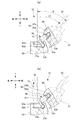
- A) is an action
- (b) is a figure which shows the state which raised the shoulder further in (a).
- FIG. 4 is a view showing a pose in which the head is further rotated and the gun is held over the shoulder in FIG. It is a figure explaining the joint of the neck of the conventional doll body, (a) is sectional drawing of a joint structure, (b) is an effect
- the doll body 10 includes a torso 20, a pair of left and right legs 30, a pair of left and right arms 40, and a head 50.
- the doll body 10 is a so-called deformed doll, and has a shape in which the leg 30, the arm 40, and the head 50 are formed relatively larger than the actual character with respect to the size of the trunk 20.
- the left and right leg portions 30 are respectively connected to the lower portion of the trunk portion 20.
- the leg portion 30 can be pivotally connected to the trunk portion 20 by various joints (not shown).
- Each of the left and right arm portions 40 has an arm portion main body 41 having a hand portion 41a at the tip, and a shoulder portion 42 formed so as to extend laterally and obliquely upward from a portion near the base end of the arm portion main body 41. Is provided.
- the base end of the arm part 40 is connected to the upper side surface of the trunk part 20 via an arm part joint 43 so as to be rotatable.
- the configuration of the arm joint 43 is arbitrary as long as the base end of the shoulder 42 is rotated at least in the vertical direction with respect to the trunk portion 20, but the arm joint 43 includes, for example, A joint having a ball joint can be used.
- the head portion 50 includes a face portion 51 provided on the front side, and corner portions 52 formed so as to extend sideways and obliquely upward from the left and right side portions of the upper portion of the face portion 51.
- the lower end of the head 50 is connected to the center of the upper end of the trunk 20 via a neck joint 60 so as to be rotatable.
- the neck joint 60 is a head-side ball comprising a joint body 61, a first shaft portion 62a (shaft portion) extending from the joint body, and a sphere portion 62b provided on the shaft portion. It has a joint 62 (head side joint) and a body side ball joint 63 b (body side joint) provided in the joint body 61. Further, the body part 20 is provided with a body part side connection part 23 for connecting the body part side ball joint 63b, and the head part 50 is connected to the sphere part 62b of the head side ball joint 62. A head-side connection portion 53b is provided.
- the head-side connecting portion 53 has a head-side recess 53a that is recessed upward from the lower end surface of the head 50, and a first spherical recess 53b that is recessed further upward from the upper surface of the head-side recess 53a.
- the body side connection part 23 has a body side recess 23a that is recessed downward from the upper end surface of the body 20 and a second spherical recess 23b that is provided in the front part of the body side recess 23a.
- the front part of the body part side recessed part 23a and the second spherical recessed part 23b are located in front of the head side recessed part 53a and the first spherical recessed part 53b.
- the joint body 61 is provided between the trunk portion 20 and the head portion 50, the spherical portion 62b of the head side ball joint 62 is inserted into the first spherical recess portion 53b, and the trunk portion side ball joint 63b is inserted into the second spherical recess portion 23b. Inserted into.
- the shape of the joint body 61 can be selected from various shapes such as a columnar shape, a prismatic shape, and a truncated cone shape. Further, the joint body 61 may be coaxial and the same diameter as a first shaft portion 62a described later, and there may be no clear boundary between the joint body 61 and the first shaft portion 62a.
- the head-side ball joint 62 has a first shaft portion 62a that protrudes upward from the upper end surface of the joint body 61, and a sphere portion 62b provided at the tip thereof. That is, the head-side ball joint 62 (head-side joint) is provided in the joint body 61 and has a first shaft portion 62 a (shaft portion) extending from the joint body 61.
- the head part 50 is freely rotatable around the spherical part 62b by fitting and holding the spherical part 62b of the head-side ball joint 62 to the first spherical recess 53b.
- the body-side ball joint 63b protrudes downward from the lower end surface of the joint body 61, and then bends and extends forward in an L-shaped second shaft portion 63a. It is the sphere part with which the tip of was equipped. That is, the trunk side ball joint 63 b (trunk side joint) is provided in the joint body 61.
- the second shaft portion 63a protrudes from the axis C passing through the center of the first shaft portion 62a (shaft portion) (in the present embodiment, protrudes forward). Therefore, the body-side ball joint 63b (body-side joint) ) Is provided at a position displaced from the axis C (a position displaced forward in this embodiment).
- the shape of the second shaft portion 63a is not limited to the L shape, and may be a straight shape protruding forward from the lower front portion of the joint body 61.
- the distal end of the second shaft portion 63a is protruded forward from the position in the front-rear direction of the spherical portion 62b of the head-side ball joint 62, and the trunk-side ball joint 63b is projected to the distal end. It can be said that it has established.
- the body side ball joint 63b is fitted to the second shaft part 63a so as to be accommodated along the bottom surface of the body side recessed part 23a and the body part side ball joint 63b is rotatably fitted to the second spherical recessed part 23b. Retained. Accordingly, the head 50 can be tilted forward so as to be pulled out in the direction indicated by the arrow (1), that is, the front side, with the body side ball joint 63b as the center.
- the head-side ball joint 62 and the head 50 can be largely rotated forward (arrow (2)). Accordingly, a large movable range ⁇ on the front side of the head 50 can be secured, and a better and appropriate pose can be realized in the doll body 10.
- the shoulder portion 42 is raised (arrow (3)).
- the large head 50 can escape to the front side with respect to the large shoulder 42.
- the shoulder 42 and the head 50 do not interfere with each other.
- the head 50 can be freely rotated to face the face 51 in the left-right direction (arrow (4)), and when the doll body 10 is viewed from the left-right direction. Also, the face 51 is not hidden by the shoulder 42. Further, even in a pose in which the gun 11 or the like is attached to the hand portion 41a and the gun 11 is held over the shoulder, the face portion 51 is not easily hidden by the gun 11 or the like, and a more attractive pose can be obtained.
- the second shaft portion 63a extends from the axis C passing through the center of the first shaft portion 62a (shaft portion) toward the front side, and as a result, the body side ball joint 63b (body portion side joint). Is provided at a position displaced from the axis C to the front side, but the second shaft part 63a extends from the axis C toward the rear side, and the body side ball joint 63b extends from the axis C to the rear side. It may be provided at a displaced position.
- the direction in which the body side ball joint 63b is displaced from the axis C may be rearward, and is arbitrary as long as it is one side. That is, the direction in which the second shaft portion 63a protrudes may be from the axis C to the rear side, and is arbitrary as long as it is one side.
- doll body 20 trunk 30 leg 50 head 60 neck joint 61 joint body 62 head side ball joint (head side joint) 62a First shaft portion (shaft portion) 62b Spherical body part 63a Second shaft part 63b Body part side ball joint (body part side joint)
Landscapes
- Toys (AREA)
Abstract
Le problème décrit par la présente invention est de fournir une articulation de cou de figure et une figure capables d'avoir une grande zone de mobilité sur le côté avant ou le côté arrière de la tête. La solution de l'invention porte sur une articulation de cou de figure (60) comprenant un corps d'articulation (61) présent entre l'extrémité supérieure d'une partie torse (20) et l'extrémité inférieure d'une partie tête (50), et une articulation sphérique pour côté tête (62) et une articulation sphérique pour côté torse (63b) présentes sur le corps d'articulation (61). L'articulation sphérique pour côté tête (62) comporte un arbre (62a) s'étendant depuis le corps d'articulation (61), et l'articulation sphérique pour côté torse (63b) est disposée dans une position décalée par rapport à l'axe de l'arbre (62a).
Applications Claiming Priority (2)
| Application Number | Priority Date | Filing Date | Title |
|---|---|---|---|
| JP2014-132231 | 2014-06-27 | ||
| JP2014132231 | 2014-06-27 |
Publications (1)
| Publication Number | Publication Date |
|---|---|
| WO2015198727A1 true WO2015198727A1 (fr) | 2015-12-30 |
Family
ID=54937825
Family Applications (1)
| Application Number | Title | Priority Date | Filing Date |
|---|---|---|---|
| PCT/JP2015/063508 Ceased WO2015198727A1 (fr) | 2014-06-27 | 2015-05-11 | Articulation de cou de figure et figure |
Country Status (1)
| Country | Link |
|---|---|
| WO (1) | WO2015198727A1 (fr) |
Cited By (4)
| Publication number | Priority date | Publication date | Assignee | Title |
|---|---|---|---|---|
| CN110841303A (zh) * | 2018-11-16 | 2020-02-28 | 株式会社万代 | 人型玩具 |
| JP2020110711A (ja) * | 2018-11-16 | 2020-07-27 | 株式会社バンダイ | 人型玩具 |
| CN112535871A (zh) * | 2019-11-28 | 2021-03-23 | 株式会社万代 | 可动构造体和人形体 |
| CN113476866A (zh) * | 2018-06-29 | 2021-10-08 | 株式会社万代 | 臂构造和人型玩具 |
Citations (3)
| Publication number | Priority date | Publication date | Assignee | Title |
|---|---|---|---|---|
| JPS6023090U (ja) * | 1983-07-22 | 1985-02-16 | 株式会社 タカラ | ロボット玩具の関節構造 |
| JPS6148790U (fr) * | 1984-08-31 | 1986-04-01 | ||
| JP2013017590A (ja) * | 2011-07-08 | 2013-01-31 | Wiz Co Ltd | 玩具 |
-
2015
- 2015-05-11 WO PCT/JP2015/063508 patent/WO2015198727A1/fr not_active Ceased
Patent Citations (3)
| Publication number | Priority date | Publication date | Assignee | Title |
|---|---|---|---|---|
| JPS6023090U (ja) * | 1983-07-22 | 1985-02-16 | 株式会社 タカラ | ロボット玩具の関節構造 |
| JPS6148790U (fr) * | 1984-08-31 | 1986-04-01 | ||
| JP2013017590A (ja) * | 2011-07-08 | 2013-01-31 | Wiz Co Ltd | 玩具 |
Cited By (14)
| Publication number | Priority date | Publication date | Assignee | Title |
|---|---|---|---|---|
| CN113476866A (zh) * | 2018-06-29 | 2021-10-08 | 株式会社万代 | 臂构造和人型玩具 |
| JP2023171644A (ja) * | 2018-11-16 | 2023-12-01 | 株式会社バンダイ | 人型玩具 |
| JP2020089398A (ja) * | 2018-11-16 | 2020-06-11 | 株式会社バンダイ | 人型玩具 |
| JP2020110711A (ja) * | 2018-11-16 | 2020-07-27 | 株式会社バンダイ | 人型玩具 |
| CN110841303A (zh) * | 2018-11-16 | 2020-02-28 | 株式会社万代 | 人型玩具 |
| CN110841303B (zh) * | 2018-11-16 | 2022-02-25 | 株式会社万代 | 人型玩具 |
| JP7679437B2 (ja) | 2018-11-16 | 2025-05-19 | 株式会社バンダイ | 人型玩具 |
| CN114832390A (zh) * | 2018-11-16 | 2022-08-02 | 株式会社万代 | 人型玩具 |
| CN114832390B (zh) * | 2018-11-16 | 2024-07-02 | 株式会社万代 | 人型玩具 |
| JP7369085B2 (ja) | 2018-11-16 | 2023-10-25 | 株式会社バンダイ | 人型玩具 |
| CN112535871A (zh) * | 2019-11-28 | 2021-03-23 | 株式会社万代 | 可动构造体和人形体 |
| CN115282609A (zh) * | 2019-11-28 | 2022-11-04 | 株式会社万代 | 可动构造体和人形体 |
| CN112535871B (zh) * | 2019-11-28 | 2022-07-26 | 株式会社万代 | 可动构造体和人形体 |
| CN115282609B (zh) * | 2019-11-28 | 2025-09-23 | 株式会社万代 | 可动构造体和人形体 |
Similar Documents
| Publication | Publication Date | Title |
|---|---|---|
| CN101405063B (zh) | 人偶玩具 | |
| KR101780600B1 (ko) | 인형체의 견관절 구조 | |
| WO2015198727A1 (fr) | Articulation de cou de figure et figure | |
| KR101834085B1 (ko) | 인형체의 관절 구조 | |
| KR102699372B1 (ko) | 인형 | |
| JP6774540B1 (ja) | 関節構造及び人形体 | |
| US20150375127A1 (en) | Doll figure | |
| WO2006124640A3 (fr) | Saisie et traitement d'images | |
| JP2016010685A (ja) | 人形体の首の関節及び人形体 | |
| CN106659941A (zh) | 人偶玩具的肩关节结构和人偶玩具 | |
| JP2017170113A (ja) | 人形玩具の手首関節構造及び人形玩具 | |
| JP5379887B2 (ja) | 人形体の腰部関節構造 | |
| TWI635445B (zh) | Double steering adjustment device for reading head of barcode reader | |
| KR20200030247A (ko) | 자석을 구비한 조인트 구조체 | |
| KR101681764B1 (ko) | 골프 클럽 헤드, 골프 클럽 | |
| JP6562894B2 (ja) | 人形体の肩関節構造 | |
| TW202007463A (zh) | 開關具有支撐功能之工具 | |
| JP2021023830A (ja) | 関節構造及び人形体 | |
| JP2019063339A (ja) | 人形の関節構造 | |
| JP5148003B1 (ja) | 人形玩具の関節構造 | |
| CN114534267B (zh) | 人形状玩具和模型的连结构件 | |
| JP2017169832A (ja) | 人形玩具の手首関節構造及び人形玩具 | |
| JP6920724B2 (ja) | Vr用メガネ | |
| USD746518S1 (en) | Attachment for headgear | |
| KR200409484Y1 (ko) | 삼중 관절 구조를 갖는 모형 인형 |
Legal Events
| Date | Code | Title | Description |
|---|---|---|---|
| 121 | Ep: the epo has been informed by wipo that ep was designated in this application |
Ref document number: 15812284 Country of ref document: EP Kind code of ref document: A1 |
|
| NENP | Non-entry into the national phase |
Ref country code: DE |
|
| 122 | Ep: pct application non-entry in european phase |
Ref document number: 15812284 Country of ref document: EP Kind code of ref document: A1 |