WO2015198736A1 - Marquage, procédé de marquage, et imprimante à jet d'encre - Google Patents
Marquage, procédé de marquage, et imprimante à jet d'encre Download PDFInfo
- Publication number
- WO2015198736A1 WO2015198736A1 PCT/JP2015/063832 JP2015063832W WO2015198736A1 WO 2015198736 A1 WO2015198736 A1 WO 2015198736A1 JP 2015063832 W JP2015063832 W JP 2015063832W WO 2015198736 A1 WO2015198736 A1 WO 2015198736A1
- Authority
- WO
- WIPO (PCT)
- Prior art keywords
- layer
- marking
- color
- developer
- ink
- Prior art date
- Legal status (The legal status is an assumption and is not a legal conclusion. Google has not performed a legal analysis and makes no representation as to the accuracy of the status listed.)
- Ceased
Links
Images





Classifications
-
- B—PERFORMING OPERATIONS; TRANSPORTING
- B41—PRINTING; LINING MACHINES; TYPEWRITERS; STAMPS
- B41M—PRINTING, DUPLICATING, MARKING, OR COPYING PROCESSES; COLOUR PRINTING
- B41M5/00—Duplicating or marking methods; Sheet materials for use therein
- B41M5/26—Thermography ; Marking by high energetic means, e.g. laser otherwise than by burning, and characterised by the material used
- B41M5/30—Thermography ; Marking by high energetic means, e.g. laser otherwise than by burning, and characterised by the material used using chemical colour formers
-
- B—PERFORMING OPERATIONS; TRANSPORTING
- B05—SPRAYING OR ATOMISING IN GENERAL; APPLYING FLUENT MATERIALS TO SURFACES, IN GENERAL
- B05C—APPARATUS FOR APPLYING FLUENT MATERIALS TO SURFACES, IN GENERAL
- B05C5/00—Apparatus in which liquid or other fluent material is projected, poured or allowed to flow on to the surface of the work
-
- B—PERFORMING OPERATIONS; TRANSPORTING
- B05—SPRAYING OR ATOMISING IN GENERAL; APPLYING FLUENT MATERIALS TO SURFACES, IN GENERAL
- B05C—APPARATUS FOR APPLYING FLUENT MATERIALS TO SURFACES, IN GENERAL
- B05C11/00—Component parts, details or accessories not specifically provided for in groups B05C1/00 - B05C9/00
- B05C11/10—Storage, supply or control of liquid or other fluent material; Recovery of excess liquid or other fluent material
-
- B—PERFORMING OPERATIONS; TRANSPORTING
- B05—SPRAYING OR ATOMISING IN GENERAL; APPLYING FLUENT MATERIALS TO SURFACES, IN GENERAL
- B05D—PROCESSES FOR APPLYING FLUENT MATERIALS TO SURFACES, IN GENERAL
- B05D1/00—Processes for applying liquids or other fluent materials
- B05D1/26—Processes for applying liquids or other fluent materials performed by applying the liquid or other fluent material from an outlet device in contact with, or almost in contact with, the surface
-
- B—PERFORMING OPERATIONS; TRANSPORTING
- B32—LAYERED PRODUCTS
- B32B—LAYERED PRODUCTS, i.e. PRODUCTS BUILT-UP OF STRATA OF FLAT OR NON-FLAT, e.g. CELLULAR OR HONEYCOMB, FORM
- B32B27/00—Layered products comprising a layer of synthetic resin
- B32B27/18—Layered products comprising a layer of synthetic resin characterised by the use of special additives
- B32B27/20—Layered products comprising a layer of synthetic resin characterised by the use of special additives using fillers, pigments, thixotroping agents
-
- B—PERFORMING OPERATIONS; TRANSPORTING
- B41—PRINTING; LINING MACHINES; TYPEWRITERS; STAMPS
- B41J—TYPEWRITERS; SELECTIVE PRINTING MECHANISMS, i.e. MECHANISMS PRINTING OTHERWISE THAN FROM A FORME; CORRECTION OF TYPOGRAPHICAL ERRORS
- B41J2/00—Typewriters or selective printing mechanisms characterised by the printing or marking process for which they are designed
- B41J2/005—Typewriters or selective printing mechanisms characterised by the printing or marking process for which they are designed characterised by bringing liquid or particles selectively into contact with a printing material
- B41J2/01—Ink jet
-
- B—PERFORMING OPERATIONS; TRANSPORTING
- B41—PRINTING; LINING MACHINES; TYPEWRITERS; STAMPS
- B41J—TYPEWRITERS; SELECTIVE PRINTING MECHANISMS, i.e. MECHANISMS PRINTING OTHERWISE THAN FROM A FORME; CORRECTION OF TYPOGRAPHICAL ERRORS
- B41J2/00—Typewriters or selective printing mechanisms characterised by the printing or marking process for which they are designed
- B41J2/005—Typewriters or selective printing mechanisms characterised by the printing or marking process for which they are designed characterised by bringing liquid or particles selectively into contact with a printing material
- B41J2/01—Ink jet
- B41J2/17—Ink jet characterised by ink handling
- B41J2/175—Ink supply systems ; Circuit parts therefor
Definitions
- the present invention relates to a thermochromic marking that irreversibly develops or changes color when exposed to a certain temperature or higher. Specifically, the present invention relates to a method for forming a thermochromic marking and an apparatus used for forming the same.
- the product If the product is not managed at an appropriate temperature during transportation or storage, the product will be altered.
- the efficacy is reduced and harmful substances are generated or increased.
- the frozen foods there are problems of alteration such as taste, flavor deterioration and spoilage due to denaturation.
- thermochromic markings that cause irreversible coloring when a certain temperature (storage upper limit temperature) is reached are being studied. This is a marking that does not develop color when the storage temperature is appropriate, but develops color when the storage temperature exceeds an appropriate value, and the color development does not disappear even when cooled again. By performing such marking, a history exceeding the proper storage temperature remains, and it is possible to determine the cause when the product is denatured.
- Patent Document 1 describes a thermochromic marking in which a color developer layer and a color former layer come into contact with each other and color is irreversibly when a certain temperature is exceeded.
- Patent Document 1 indicates that the upper limit temperature of storage has been exceeded simply by irreversible color development, and there was no idea of adding other information.
- the color former layer can be formed with fine dots, etc., it will be possible to develop colors in the form of symbols and letters, so not only the management status of storage temperature due to color development is known, but also the name of the factory that manufactured the product, Information such as the production number and the production date can also be entered as hidden characters.
- information such as a bar code and a matrix type two-dimensional code can be printed, logistics can be easily managed by providing a reader for reading the information at a product delivery place.
- One aspect of the present invention is a method of forming a marking that develops a color when the temperature exceeds a specified temperature on a substrate.
- This method includes a first step of forming a first member containing a developer or a color former on a substrate, a second step of forming a barrier layer that covers the first member, and a developer on the barrier layer. And a third step of forming a second member including a colorant or a color former different from the first member.
- At least one of the first step and the third step includes a step of forming a liquid containing a developer or a color former into droplets, and a step of depositing the liquid droplets on the substrate or the barrier layer.
- Another aspect of the present invention includes an ink container that stores ink, an inkjet head that ejects ink droplets, and an ink supply path that supplies ink from the ink container to the inkjet head.
- This is an ink jet printer that forms an arbitrary pattern on a substrate.
- the printer has a cooling device that can be cooled to maintain at least a portion of the ink at a temperature below 15 degrees Celsius.
- Another aspect of the present invention is a marking formed on a substrate.
- This marking consists of a developer layer, a barrier layer, and a color former layer formed on the substrate.
- the barrier layer has a configuration in which the developer layer and the color former layer are kept in non-contact at the first temperature, and the developer layer and the color developer layer are brought into contact at the second temperature.
- At least one of the developer layer and the color developer layer is formed in a plurality of dot shapes, and a predetermined pattern is formed by the plurality of dots. Then, when the developer layer and the color former layer are in contact with each other at the second temperature, the color former layer is colored, and a predetermined pattern is visualized.
- the dot shape means that the layer has an intermittent structure in the horizontal direction.
- the dots are approximately circular with a diameter of 0.3 to 0.5 mm, and the dot interval is 0.3 to 0.5 mm.
- the shape, size, and interval of the dots are not limited to this.
- the color former is colorless or light-colored when it comes into contact with a product such as a pharmaceutical product or frozen food (hereinafter referred to as a printing substrate), and develops color upon contact with an acidic or basic chemical.
- a product such as a pharmaceutical product or frozen food (hereinafter referred to as a printing substrate)
- develops color upon contact with an acidic or basic chemical defined as a drug.
- the developer is defined as a colorless or light-colored drug that exhibits acidity or basicity.
- the barrier layer when the barrier layer reaches a temperature or higher, the developer and the color former come into contact with each other by dissolving or softening, and the color development of the color former starts.
- the layer structure can be the order of the developer, the barrier layer, and the color developer on the surface of the printing equipment, or the order of the color developer, the barrier layer, and the developer.
- a developer layer is formed on the surface of the printing equipment.
- a barrier layer is formed on the developer layer that dissolves or softens when the temperature exceeds a certain temperature.
- the color former is printed by a charge control type ink jet printer or the like.
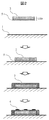
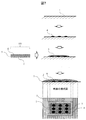
- Fig. 1 shows this formation process and formation state.
- the developer layer 2 is formed on the substrate 1. At the time of formation, it is formed by a method in which a solution in which a developer is dissolved is applied and then dried, or a method in which a porous agent that has absorbed the developer is attached.
- the barrier layer 3 is formed on this.
- a coating method such as roll coating is preferred.
- the developer layer and the barrier layer are basically formed in a layer having a substantially uniform thickness.
- the color former layer 4 is formed on this. This is an information display of only a temperature history in a uniform layer structure. Therefore, it is desirable to form fine dots in order to form a large amount of recording information.
- the barrier layer when the barrier layer has a property of dissolving at 5 ° C., the barrier layer dissolves at 5 ° C. or more, and the developer layer and the color former layer having a fine dot structure come into contact with each other, and the color developing layer develops color.
- Figure 2 shows an example using the film structure.
- a film 100 having a developer layer 2 formed on the front surface and an adhesive layer 5 formed on the back surface is formed in advance.
- the marking of the present invention is completed by pasting this on the substrate 1 and forming the barrier layer 3 and the color former layer 4 thereon. Since the developer 2 can be formed by sticking, there is an advantage that the marking of the present invention can be easily formed.
- a film substrate made of polyethylene, polypropylene, or the like may be present between the developer layer 2 and the adhesive layer 5. In this case, the developer layer 2 is formed on one side of the film substrate, and the adhesive layer 5 is formed on the opposite side.
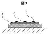
- FIG. 3 is a diagram showing another example of the sectional structure of the created marking.
- the developer layer 2 was covered with the barrier layer 3.
- the color developer layer 4 may come off the barrier layer 3 and adhere to the developer layer 2. There is sex. In that case, there is a risk of color development even if the barrier layer 3 is not dissolved. Therefore, it is desirable that the developer layer 2 is covered with the barrier layer 3, that is, the developer layer 2 is smaller than the barrier layer 3.
- the color former layer 4 may be rubbed with a finger or the like during product transportation and peeled off. In this case, the coloring effect may be lost.
- Fig. 4 is a diagram showing a cross-sectional structure of the marking in consideration of contact of the finger with the marking.
- a cover layer 6 may be provided on the color former layer 4 as shown in FIG.
- the material of the cover layer needs to be transparent or almost transparent in the visible region so that the color of the color developing layer can be visually confirmed.
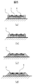
- FIG. 5 is a diagram showing another example of the cross-sectional structure of the marking in consideration of the contact of the finger or the like with the marking.
- a method of raising the end of the developer layer 2 as shown in FIG. This can be created by, for example, coating the end portion a plurality of times when applying the developer layer.
- Such a structure is preferable because the abrasion resistance is improved even when the developer layer 2 is larger than the barrier layer 3.
- the shape to be raised is a structure with slightly reduced corners in that it can disperse energy during rubbing as in (b), A structure in which the corners of the end portions are completely dropped as described above, and a structure in which the cover layer 6 is provided as shown in FIG.
- (d) provided with the cover layer 6 may have a structure most resistant to rubbing.
- it takes the most labor to form there is a possibility that the price of the products that form it is limited to those that are somewhat expensive.
- the raised portion is a part of the developer layer 2, but from the viewpoint of protecting the color developer layer 4, it is not necessary to be a developer, and any raised portion is sufficient. However, in order to simplify the process, it is preferable to use a developer.
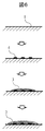
- a method of forming a color former layer, a barrier layer, and a developer layer in this order on the printing substrate After forming the color former layer using an electric control type ink jet printer, etc., and cooling to the storage temperature, a certain amount A barrier layer that dissolves or softens when the temperature is exceeded is provided, and then a developer layer is formed.
- Figure 6 shows a cross-sectional view of the formation process.
- the color former layer 4 is formed on the surface of the printing substrate 1.
- a barrier layer 3 is formed on the color former layer 4 by coating by roll coating or the like.
- the developer layer 2 is formed by applying a solution in which the developer is dissolved.
- Fig. 7 shows a cross-sectional view of another forming process.
- the color former layer 4 and the barrier layer 3 are formed.
- a film 101 having a color developing layer 2 and an adhesive layer 5 formed on the back surface of the cover layer 6 is used. Since the cover layer 6 of the film 101 is the outermost surface, the film 101 is preferable in that it becomes a protective layer for enhancing the abrasion resistance of the marking. In this case, it is desirable that the barrier layer 3 is completely covered with the developer layer 2 and the cover layer 6. Thereby, even if the marking site is rubbed, the film 101 protects the marking, so that it is possible to suppress the problem of color development even if the barrier layer 3 is not dissolved or softened.
- the film base is used as a cover layer 6 for marking protection.
- the barrier layer, developer layer, film, etc. that are superimposed on the color forming layer are materials that absorb little in the visible region so that the color developing layer can be recognized when the color develops. It is necessary to choose. In addition, in the case of a material with low transparency and turbidity, light is scattered and it may not be possible to determine the presence or absence of color development. Therefore, a material with low scattering is also desired.
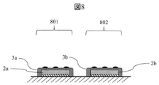
- FIG. 8 shows an example of the cross-sectional structure of the marking according to the present invention.
- the geometric configuration of the marking in FIG. 8 is the same as the example in FIG. The difference is that the melting temperature of the barrier layer 3 is different between the plurality of markings 801 and 802. For example, it is assumed that the barrier layer 3a is dissolved at A ° C. and the other barrier layer 3b is dissolved at B ° C. Also assume that B ° C is higher than A ° C. First, the barrier layer 3a is applied on the developer layer 2a. Next, the barrier layer 3b is applied on another developer layer 2b.
- the marking 801 coated with the barrier layer 3a developed color
- the marking 802 coated with the barrier layer 3b did not develop color. You can see that it was placed.
- two types of barrier layer materials are used for the barrier layer 3, but by using another barrier layer material having a different melting temperature from these, it becomes possible to examine the history of the storage temperature in more detail.
- FIG. 9 shows another example of the cross-sectional structure of the marking according to the present invention.
- the geometric configuration of the marking in FIG. 9 is the same as the example in FIG. The difference is that the melting temperature of the barrier layer 3 differs between the plurality of markings 901 and 902.
- the barrier layer 3a is dissolved at A ° C.
- the other barrier layer 3b is dissolved at B ° C.
- B ° C is higher than A ° C.
- the barrier layer 3a is applied on a certain color former layer 4a.
- the barrier layer 3b is applied on another color former layer 4b.
- the temperature history can be examined in detail as in the example of FIG. 9 as well, the history of storage temperature can be examined more finely.
- Color former layer material The materials shown here are usually colorless or light-colored by visual observation, but correspond to substances that change color by touching an acidic substance or basic substance and visually develop color. However, here, a substance that is almost colorless or pale in the vicinity of neutrality at a pH of about 5 or more and less than pH 8, and that develops a color at a pH of less than about 5 is referred to as a "substance that develops color by touching an acidic material". A substance that develops color when touched by sexual materials.
- the product storage environment should be solid so that it does not flow when the product after marking is tilted and stored at various angles.
- Substances that develop color when in contact with acidic materials include methyl violet carbinol base, malachite green carbinol base, thymol blue, methyl yellow, and methyl orange.
- a basic polymer is mixed in the color former layer when the color former layer comes into contact with an acidic substance.
- the color former layer can be formed in a substantially uniformly dispersed state after mixing with the color former layer material.
- polyethyleneimine, polyallylamine and the like are suitable.
- the material shown here is an acidic substance or a basic substance, and this is also a product storage environment so that it does not flow when storing the product after forming the marking at various angles. Then, a solid thing is desirable. For example, when the product is stored at room temperature, a solid product is desirable at room temperature (approximately 30 ° C. or less). In addition, it is desirable to be amorphous in order to form a substantially uniform layer structure.
- Acidic substances examples include polymers having a carboxyl group or a sulfonic acid group. Specifically, polyacrylic acid, polymethacrylic acid, polystyrene sulfonic acid, copolymer of styrene and polyacrylic acid, copolymer of methyl acrylate and acrylic acid, copolymer of ethyl acrylate and acrylic acid, acrylic Copolymer of propyl acid and acrylic acid, copolymer of butyl acrylate and acrylic acid, copolymer of hexyl acrylate and acrylic acid, copolymer of octyl acrylate and acrylic acid, methyl methacrylate and acrylic acid Copolymer, Copolymer of ethyl methacrylate and acrylic acid, Copolymer of propyl methacrylate and acrylic acid, Copolymer of butyl methacrylate and acrylic acid, Copolymer of hexyl methacrylate and acrylic acid, Me
- aliphatic carboxylic acids that are solid at room temperature, specifically decanoic acid having a melting point of 30 ° C., and dodecanoic acid, tetradecanoic acid, hexadecanoic acid, octadecanoic acid, etc. having a higher carbon number are also low in crystallinity. Is easy to form. Furthermore, it is more preferable to use a mixture of these dicarboxylic acids because the crystallinity is lowered.
- the dicarboxylic acid having two carboxyl groups has a melting point of 189 to 190 ° C. even with the smallest oxalic acid having 2 carbon atoms, and is solid at room temperature.
- a dicarboxylic acid having a large carbon number is preferred because of its high crystallinity.
- Adipic acid and the like are easily crystallized when the number of carbon atoms is short. Therefore, dicarboxylic acids having a large number of carbon atoms, specifically, sebacic acid having 10 carbon atoms, 12 dodecanoic acids, 14 tetradecanoic acids, 16 hexadecanoic acids and the like can be mentioned. Further, as in the case of carboxylic acid, the use of a mixture of these dicarboxylic acids is more preferred because the crystallinity is lowered.
- Basic substance examples include polymers having amino groups such as polyethyleneimine, polyallylamine, chitosan, polylysine, polyarginine, and polyaniline. Also, Aliphatic diamines that are solid at room temperature, specifically diaminohexane, diaminooctane, diaminodecane, diaminododecane, and the like are also suitable because they are easy to form a developer layer because of their low crystallinity.
- Monoamine has a melting point not higher than room temperature unless the carbon number is considerably increased, but is preferred because it is solid at room temperature when it has 14 or more carbon atoms.
- Specific examples include tetradecylamine having 14 carbon atoms and a melting point of 37 ° C., hexadecylamine having 16 carbon atoms, and octadecylamine having 18 carbon atoms.
- the material of the color former layer is weak in color and may have low visibility when it is in contact with an acidic or basic color developer layer.
- phenolphthalein produces a very light pink color when water is not present together, but a good pink color appears when water is slightly present.
- barrier layer material The material shown here is provided between the developer layer and the color former layer, and acts as a barrier so that they do not contact each other until the specified temperature is reached.
- the barrier layer material preferably has a structure having as little acidic groups as carboxyl groups, sulfonic acid groups, and phenolic hydroxyl groups, and basic groups such as amino groups. This is because even if the barrier layer is not softened or dissolved, these acidic groups or basic groups may react with the color former and the color former may be colored.
- candidate materials for the barrier layer include acidic hydrocarbons, long-chain hydrocarbons not containing basic groups, or some branched hydrocarbons.
- an alcohol having a long hydrocarbon chain or a branched hydrocarbon chain, a diol, a ketone, an amide having a long hydrocarbon chain or a branched hydrocarbon chain, an ether, an ester, and the like can be given.
- the barrier layer material is composed of hydrocarbons having 10 to 18 carbon atoms.
- the barrier layer material is composed of a mixture of two or more of hydrocarbons having 10 to 18 carbon atoms.
- decane As hydrocarbons of long or branched hydrocarbon chains or cyclic hydrocarbon chains, decane (-30 ° C), 2-methylnonane (46 ° C), cyclodecane (9 ° C), dodecane (-12 ° C), tetradecane (6 ° C), hexadecane (17 ° C), octadecane (28 ° C) and the like.
- the parentheses are melting points.
- Hydroxyl-terminated alcohols or diols include 1,3-propanediol (-59 ° C), 1,4-butanediol (20 ° C), 1,6-hexanediol (40 ° C), 1,2-octane Diol (37 ° C), 1-octanol (-16 ° C), 1-decanol (6 ° C), 1-dodecanol (24 ° C), 1,2-dodecanediol (58 ° C), 1,12-dodecanediol (82 ° C), 5,6-dodecanediol (47 ° C), 1-tetradecanol (38 ° C), 2-tetradecanol (34 ° C), 7-tetradecanol (42 ° C), 1-hexadecanol ( 50 ° C).
- Materials with a ketone structure include 2-octanone (-16 ° C), 3-octanone (-23 ° C), 2-decanone (3 ° C), 2-dodecanone (-20 ° C), 3-dodecanone (-19 ° C) ), 2-tetradecanone (35 ° C), 3-tetradecanone (34 ° C), 3-hexadecanone (43 ° C), propiophenone (18 ° C), butyrophenone (12 ° C), isobutyrophenone (1 ° C), hexanophenone (26 ° C.), octanophenone (22 ° C.), decanophenone (35 ° C.), dodecanophenone (45 ° C.), tetradecanophenone (53 ° C.), hexadecanophenone (59 ° C.) and the like. The temperature of the melting point is shown in parentheses.
- barrier layer materials depend on the storage upper limit temperature of the product to be marked. For example, in the case of frozen foods made from meat, since it is around -16 ° C, a compound such as 1-octanol or 2-octanone having a melting point of -16 ° C is provided in the barrier layer. If it is stored at a slightly lower temperature for seafood, 3-octanone with a melting point of -23 ° C is a candidate. For carbohydrate-based products, dodecane with a melting point of -12 ° C is a candidate for storage at a slightly higher temperature.
- barrier materials can be used alone, but by mixing a compound having a higher melting point than that, the crystallinity is lowered and becomes amorphous, so the barrier layer becomes dense and the color former. This is preferable because the shielding property between the layer and the developer layer is improved.
- the amorphousness is enhanced by mixing a compound having a similar structure.
- a compound having a similar structure For example, by adding tetradecane having a melting point of 6 ° C or hexadecane having a melting point of 17 ° C to dodecane having a melting point of -12 ° C, the barrier layer becomes amorphous, and between the color former layer and the developer layer. Shielding is improved.
- the temperature at which the barrier layer softens depends on the melting point and the addition rate of the mixed material. For example, when an equal amount of a material a having a high melting point A ° C. and a material b having a melting point B ° C. are mixed in equal amounts, the melting point is approximately between A and B. However, when the difference between the melting points of the two materials is large, specifically, when the temperature is 50 ° C. or higher, the temperature at which the barrier layer softens or dissolves is substantially the same as the melting point of the material with the lower melting point. Further, when materials having low compatibility are used, the temperature at which the barrier layer is softened or dissolved is substantially the same as the melting point of the material having a lower melting point.
- the product to be marked is a pharmaceutical product requiring storage below 10 ° C, tetradecane with a melting point of 6 ° C, or 1-decanol, or 2-dodecane with a melting point of 3.5 ° C, hexadecane with a melting point of 17 ° C, or a melting point of 19
- 3-dodecanone at 20 ° C and 2-dodecanone at 20 ° C to adjust the melting point to approximately 10 ° C.
- the outermost surface is a film
- the physical strength of the marking of the present invention is improved, and the outermost film guards even if it is slightly rubbed.
- the material of the film is preferably a material such as polyethylene or polypropylene because it is inexpensive and can withstand various organic solvents.
- the adhesiveness is difficult because various adhesive materials are repelled.
- it since it is a crystalline polymer, when it is thick, the film becomes whitish, light transmittance is lowered, and it is difficult to determine whether or not the marking is colored. Therefore, a polyethylene terephthalate (PET) film is an example of a resin that easily imparts adhesion and transparency in addition to solvent resistance. Since this resin is amorphous, it has high transparency and high solvent resistance, and is insoluble in general-purpose organic solvents such as acetone and alcohol. Moreover, since the critical surface tension is large compared to hydrocarbon resins such as polyethylene and polypropylene, the adhesiveness is excellent.
- the cover layer 6 shown in FIGS. 4 and 7 is desirably visually transparent or light so that the color of the color former layer can be visually confirmed. Since the human eye is highly sensitive to visible light having a wavelength of 400 to 700 nm, a material having as little absorption as possible in this wavelength region is a candidate for the cover layer material. In order to improve visibility, an amorphous material is preferable to a material having high crystallinity. Specifically, amorphous PET resin, polycarbonate resin, acrylic resin, or the like is preferable to polyethylene or polypropylene, which are crystalline polymers. However, it is possible to use a crystalline resin by improving the light transmittance by forming a thin cover layer.
- the cover layer material is a member that does not dissolve the color former layer, the barrier layer, and the developer layer. Furthermore, when the cover layer material is dissolved in an organic solvent, and then applied on the color former layer, barrier layer, and developer layer, and the cover layer is formed, the solvent in which the cover layer material is dissolved is colored. It is necessary to select one that does not dissolve the agent layer, barrier layer, and developer layer.
- An apparatus for forming a marking requires an apparatus for forming a developer layer, an apparatus for forming a barrier layer, and an apparatus for forming a color former layer. In some cases, an apparatus for forming a cover layer is also required.
- the printed part is not only flat, but in the case of ampoules, it is necessary to print on a cylindrical curved surface.
- this embodiment shows an example in which the principle of an ink jet printer is applied as a configuration capable of printing in various shapes at high speed.
- the temperature inside the apparatus is as high as 40 to 50 ° C. even when the room temperature is about 20 ° C. due to heat generation from a built-in pump, electronic substrate and the like. Therefore, even if the ink tank is taken out of the apparatus, the ink may be 20 ° C. or higher.
- a barrier layer is already formed on the object side, and when printing on the object, it is necessary to control the temperature of the ink so that the barrier layer is not damaged by the heat of the ink.
- the temperature of the ink can be taken into consideration so that the heat of the printed ink does not affect the barrier layer to be formed later. desirable.
- Patent Document 2 shows a configuration in which the temperature of ink is set to a specified temperature (15 to 40 ° C.) in order to maintain print quality.
- the temperature for maintaining the quality of the pharmaceutical is less than 15 ° C., preferably 10 ° C. or less, and the marking needs to be formed below this temperature (ie, the barrier layer needs to be kept below this temperature).
- the cold place is set to 1 ° C to 15 ° C.
- it is ideal if it can be stored at 2-8 ° C.
- the temperature for maintaining the quality of the frozen food in the distribution process is 0 ° C. or lower, preferably minus 20 ° C. or lower, and the marking needs to be formed below this temperature.
- the temperature of a freezing room for home use In the Japanese Industrial Standard (JIS 9607 electric refrigerator and electric freezer), three types of temperatures of minus 6 ° C or less, 12 ° C or less, and 18 ° C or less are defined as the temperature of a freezing room for home use. Therefore, it is necessary to enable cooling at a temperature lower than the specified temperature of normal printing ink in the apparatus of the present embodiment that can form markings for temperature history management instead of normal printing applications.
- the marking forming apparatus of the present embodiment is used in an environment of, for example, 10 ° C. or lower for pharmaceutical products and 0 ° C. or lower for frozen foods.
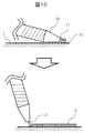
- FIG. 10 is a schematic diagram of a layer forming mechanism of the marking forming apparatus of the present invention.
- the developer 12 is discharged from the opening 11 of the hopper 10 filled with the developer, and then applied onto the substrate 1.
- the width and thickness of the developer layer 2 are controlled by the size of the opening 11.
- the developer band is cut with the squeegee 13 by raising the hopper 10.
- tank of the developer material to be used and general equipment such as a compressor used when the developer material is sent from the tank to the hopper are omitted in this figure.
- the developer is used in a form dissolved or suspended in some organic solvent.
- a heating mechanism capable of heating a portion in contact with the barrier layer material such as a hopper is provided. At the time of application, a heating mechanism is operated to dissolve and apply the barrier layer material.
- Fig. 10 In addition to the equipment shown in Fig. 10, it can also be formed with a bar coater, applicator, etc., but these can be used for small lots, but they are not suitable for mass production. Shape is preferred.
- FIG. 11 is a schematic diagram of a developer layer forming mechanism of the marking forming apparatus of the present invention.
- This device configuration consists of a mechanism that cuts the film on which the developer layer is formed at a certain length, a mechanism that affixes the cut film onto a substrate or barrier layer, and a barrier layer that has a certain thickness is applied and formed. And a mechanism for forming the color former layer on the substrate or the barrier layer in the form of droplets of the color former.
- the film 100 is pulled out from the cylinder 14 around which the film 100 on which the developer layer 2 is formed is wound, and the film 100 is pasted on the film end pasting site 17 in front of the blade 16 of the rotary cutter 15.
- the film 100 used the configuration shown in FIG.
- the rotary cutter is rotated 90 ° counterclockwise, and the film 100 is cut with the blade 18 of the rotary cutter 15.
- the cut film 100 is affixed to the substrate by lowering the rotary cutter 15 to bring the film 100 into contact with the substrate 1 or by lifting the substrate 1 up and bringing the film 100 into contact with the substrate 1.
- the film 100 on the cylinder 14 side is applied to the blade 18 of the rotary cutter 15 by the adhesive layer of the film. In this way, the film 100 can be stuck on the substrate 1 one after another.
- FIG. 12 shows a schematic cross-sectional view of an example of a film formed with the color developing layer of the present invention used in FIG.
- the film 100 is provided with an adhesive layer 20 on the back surface of the film base 19 on which the developer layer 2 is formed, so that it can be attached to a product.
- this film is wound in a roll shape, the adhesive layer 20 and the developer layer 2 have low releasability and may not be easily peeled off.
- a release film 21 is provided on the adhesive layer 20.
- the pressure-sensitive adhesive layer 20 and the developer layer 2 are strongly bonded to each other, and it is possible to prevent a problem that the developer layer 2 is damaged when peeled off.
- the release film 21 is provided, for example, in the example of FIG. 11, a process of peeling the release film 21 may be added before the film 100 is attached to the substrate 1.
- the release film 21 is preferably made of polyethylene or polypropylene having a small critical surface tension, and a thin coating of silicone oil having a polydimethylsiloxane chain as a basic skeleton can further improve the release property. Is preferred.
- the apparatus for forming the color former layer is preferably a solid coating so that the barrier layer can be easily visually observed when it is desired to change the color tone due to the softening or dissolution of the barrier layer.
- an apparatus for forming the developer layer is effective.
- the color tone changes due to temperature rise
- a printing method using a liquid in which a color former is dissolved as an ink is suitable, and one of them is an ink jet printer.
- the ink jet printer used in this case is preferably a charge control type ink jet printer capable of printing on a non-flat product such as a large surface unevenness or a cylindrical shape.
- FIG. 13 shows a schematic diagram of the printing process by the color former layer forming mechanism of the marking forming apparatus of the present invention.
- Ink pressurized by a pump in the apparatus becomes an ink droplet 22 of a desired size by a vibrator inside the apparatus, is ejected from a nozzle 23, is charged by a charging electrode 24, and then deflected. The direction is controlled by the electrode 25 and land on the substrate 26. Ink that is not printed is collected from the gutter 27 and returned to the ink tank (not shown in FIG. 13).
- an arbitrary pattern can be drawn on the printing material 26 with the ink droplets 22.
- the color former layer material is dissolved in some organic solvent and printed in a solution state.
- the viscosity at that time is desirably 5 mPa ⁇ s or less. If the viscosity is higher than this, not only is it difficult to eject, but also the ink breakage becomes unstable, and the size of the ink droplets is not constant, so that the dot size formed on the product substrate varies and the printing becomes difficult to see.
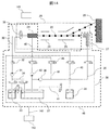
- FIG. 14 is a schematic diagram of the color former layer forming mechanism of the marking forming apparatus of the present invention. An ink flow path and a solvent flow path are shown in the form of an ink jet printer.
- the ink jet printer of the present invention comprises a main body 28 and an ink jet head 29 of the ink jet printer.
- the ink supply path 30 is provided with a supply pump 31 and an adjustment valve 32.
- the main body 28 is provided with a sub container 33 for containing ink.
- Ink supply is usually performed by the user supplying ink to the sub container 33.
- the replenished ink passes through a filter or the like (not shown) to remove impurities, and is accumulated in the main container 37.
- the ink in the main container 37 is supplied to the nozzles 23 through the ink supply path 34 connected to the ink supply path 30. If the remaining amount of ink in the main container is insufficient, the ink in the sub container 33 can be supplied to the nozzles 23.
- an ink collection path 35 is connected to the gutter 27, and the ink that is captured by the gutter 27 is collected by the collection pump 36 in the main container 37.
- the main body 28 is provided with a solvent container 38 for storing the ink solvent.
- a solvent supply path 40 is connected to the ink flow path switching valve 39 provided in the ink supply path 30 in order to supply the solvent in the solvent container 38 to the nozzles 23.
- the solvent in the solvent container 38 is supplied to the nozzle 23 via the ink flow path switching valve 39. Further, the solvent in the solvent container 38 is supplied to the main container 37 through a branch path 41 connected to the solvent supply path 40.
- the supply of the solvent from the solvent container 38 to the main container 37 is a mechanism for replenishing the solvent volatilized by the printing operation.
- the replenishment is automatically performed when the viscosity of the ink in the main container 37 becomes higher than a specified value due to solvent volatilization.
- a viscosity measuring mechanism (not shown in this figure) is provided in the main container 37.
- the sub container 33, the main container 37, and the solvent container 38 are formed of a resin such as polyethylene or polypropylene.
- a resin such as polyethylene or polypropylene.
- a suction pump 42 is provided, and an ink return channel 43 is connected to the nozzle 23.
- the solvent in the solvent container 38 is supplied to the nozzles 23 via the ink flow path switching valve 39, and the nozzles 23 are washed.
- the solvent after washing is returned to the main container 37 by the suction pump.
- a replenishment path 44 is connected between the ink supply path 30 and the ink recovery path 35, and ink in the sub-container 33 is replenished into the main container 37 via the replenishment path 44.
- Each channel is provided with an on-off valve (not shown in this drawing) for opening and closing the channel according to the flow of liquid such as ink and solvent in the channel. Further, the various valves 46 provided in the flow path control the liquid conveyance in the direction indicated by the arrow.
- the color former becomes very small ink droplets 22 and lands on the barrier layer on the printed material 26, if the melting point of the barrier layer is not very low, the possibility of dissolving the barrier layer is small. Further, since the ink droplets themselves are cooled due to the vaporization of the solvent contained, the ink droplets that land on the product are cooler than the temperature of the ink inside the ink jet printer.
- the impacted ink droplets dissolve the barrier layer, and the developer layer and the coloring layer come into contact with each other. There is a possibility that color will develop even though it is stored at the specified temperature. Therefore, it is preferable that the color developing agent solution to be printed is cooled as much as possible inside the ink jet printer, so that the risk of softening or dissolving the barrier layer at the time of marking is reduced.
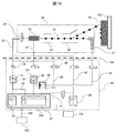
- the ink flow path and the solvent flow path before the nozzle 23, the various valves, the sub container 33, the main container 37, and the solvent container 38 are cooled. These were put together and the cooling part 45 was enclosed with the dotted line. Since the solvent is supplied from the solvent container to the main container 37 and the like, the stability of the ink is enhanced by cooling the solvent at that time. It is desirable that the cooling temperature be not higher than the temperature at which the barrier layer is dissolved or softened.
- the refrigerant is supplied to the cooling part 45 through the refrigerant pipe 142, and the heat is exhausted to the outdoor unit 143 by a known heat exchanger that compresses, liquefies, decompresses and vaporizes the refrigerant.
- a Peltier element or the like may be used.
- kinetic energy is given to the ink droplet 22 by the pressure of the supply pump 31 and the electrostatic force of the charging electrode 24.
- the ink may be ejected from the nozzles by thermal energy generated from the heating element.
- FIG. 15 is a schematic view showing another example of the color former layer forming mechanism of the marking forming apparatus of the present invention. Since the basic configuration is similar to that of FIG. 14, the same components as those of FIG.
- Fig. 15 shows a more efficient cooling method.
- the parts that need to be cooled are tanks that store ink and have a large heat capacity.
- the main container 37 is important because it is directly connected to the nozzle 23.
- the part that becomes the heat source in the apparatus is the pressure pumps 31, 42, 36, etc. installed in each flow path. Since these generate heat, they are preferably insulated or cooled.
- the ink supply path 30 that connects the main container 37 and the nozzles 23 has the greatest need for cooling or heat insulation.
- a mechanism for cooling at least a part of the liquid or the barrier layer is provided to prevent the coloring of the marking during the formation of the marking.
- the sub container 33 and the main container 37 are separated by the heat insulating wall 150 and cooled by the heat exchanger.
- the pressure pumps 31, 42 and 36 are also isolated by the heat insulating wall 151 and cooled by a heat exchanger (not shown).
- the ink supply path 30 has a heat insulating structure with a heat insulating material.
- the housing of the ink jet printer should also have a heat insulating structure. For example, if the operating environment (outside the apparatus) temperature is about 0 ° C. or higher, condensation may occur. If there is a temperature difference between the low-temperature main body containing the ink container and the head, which is the operating environment temperature, a heat insulation wall should be provided at least between the main body and the head to prevent condensation on the head side. That's fine.
- heat insulation refers to preventing heat transfer
- examples of efficient heat insulation include a wall structure composed of fiber-based heat insulating materials such as glass wool, and foam-based heat insulating materials such as urethane foam.
- the temperature to be cooled can be obtained by calculation based on the size of the device, the material of the device, the specific heat of the ink, the size of the ink droplet, the thickness of the barrier layer on the substrate, and the like.
- a trial writing is performed on the barrier layer on the substrate 26, and the temperature control may be performed with a target of the temperature at which the printing has been successfully performed.
- These controls can be executed by inputting a command for controlling the cooling device from the control terminal 152.
- a cooling member 153 that cools the printed material 26 itself is provided. If the cooling member 153 and the cooling mechanism on the ink jet printer side are used in combination, the cooling effect is further enhanced. If the barrier layer is not altered or colored by printing, one of the cooling member 153 and the cooling mechanism on the ink jet printer side may be omitted.
- (3) Device for forming the cover layer The cover layer dissolves resin in some organic solvent, and the solution is poured onto the marking using a dispenser or the like. Thereafter, the cover layer can be formed by drying and volatilizing the organic solvent contained therein. Further, it can be formed by a general method such as photocuring using energy such as light.
- marking can be formed on a non-flat member at high speed.
- Polyacrylic acid is an acidic polymer having a carboxyl group.
- cyclodecane with a melting point of 9 ° C. and tetradecane with a melting point of 6 ° C. are put into a glass container of the same weight, and stirred and mixed with an overhead stirrer to prepare a barrier layer material.
- the melting point of the prepared barrier layer material was examined, it was about 8 ° C.
- This is filled in the apparatus shown in FIG. 10 and applied onto a PET film having a developer layer formed on a pharmaceutical paper package.
- the average thickness of the barrier layer after application is 40 ⁇ m.
- the room temperature during application is controlled to 5 ° C or lower.
- the surface temperature of a pharmaceutical paper package with a PET film with a developer layer attached is also controlled to 5 ° C or less.
- a barrier layer is formed on the developer layer.
- thermochromic marking of the present invention is completed.
- malachite green carbinol base is light brown in the state of 2-butanone solution, but when it comes into contact with an acidic substance, it turns dark green.
- thermochromic confirmation experiment Transfer the paper package of the medicine for which thermochromic marking has been completed to a room temperature of 25 ° C. Then, about 1 minute after the transfer, the number “123456789” appeared in green in the part where the thermochromic marking was formed. I returned to the room at room temperature 5 ° C again, but the numbers did not disappear.
- thermochromic marking portion When the thermochromic marking portion was analyzed, the barrier layer was dissolved, and it was determined that the malachite green carbinol base and polyacrylic acid were in contact with each other, and a green color was developed.
- thermochromic marking was formed on a pharmaceutical paper package by the same process as in Example 1 except for the barrier layer material. When the melting point of the prepared barrier layer material was examined, it was about 7 ° C.
- polyacrylic acid 10 g
- water 190 g
- Polyacrylic acid is dissolved to prepare a 5 wt% aqueous solution.
- This is filled in the apparatus shown in FIG. 10, and applied to a PET film having a thickness of 125 ⁇ m and having an adhesive layer and a release film on the back surface so that the solution thickness is about 40 ⁇ m.
- the developer is dried at 60 ° C. for 8 hours, and a developer layer made of polyacrylic acid having an average thickness of 2 ⁇ m is formed on the PET film.
- the PET film is attached to a frozen food PET film package using the apparatus shown in FIG.
- 1-octanol with a melting point of ⁇ 16 ° C. and 2-dodecanone with a melting point of ⁇ 20 ° C. are put into a glass container of the same weight, and stirred and mixed with an overhead stirrer to prepare a barrier layer material.
- the melting point of the prepared barrier layer material was examined, it was about -19 ° C.
- This is filled in the apparatus shown in FIG. 10 and applied onto a PET film having a developer layer formed on a pharmaceutical paper package.
- the average thickness of the barrier layer after application is 40 ⁇ m.
- the room temperature during application is controlled to -20 ° C or lower.
- the surface temperature of a frozen food PET film package to which a PET film with a developer layer is attached is also controlled to -20 ° C or lower.
- a barrier layer is formed on the developer layer.
- thermochromic marking of the present invention is completed.
- the cooling portion 45 of the ink jet printer is desirably ⁇ 20 ° C. or lower, but the thermochromic marking of the present invention can be formed even at ⁇ 5 to 0 ° C. as in this embodiment. This is because the amount of malachite green carbinol-based 5 wt% 2-butanone solution that lands on the barrier layer during printing is small, and does not have enough heat to dissolve the barrier layer. Moreover, since the heat of vaporization when 2-butanone volatilizes after landing on the barrier layer is taken away from the barrier layer, it is rather cooled slightly. However, when the temperature exceeds 0 ° C., when the barrier layer of this embodiment is used, the barrier layer starts to dissolve slightly. Therefore, under the conditions of this embodiment, the cooling portion of the ink jet printer needs to be 0 ° C. or lower.
- thermochromic confirmation experiment Move the PET film package of frozen food that has completed thermochromic marking into a room at room temperature of 5 ° C. Then, about 1 minute after the transfer, the number “123456789” appeared in green in the part where the thermochromic marking was formed. I returned to the room at room temperature -20 °C again, but the numbers did not disappear.
- thermochromic marking portion When the thermochromic marking portion was analyzed, the barrier layer was dissolved, and it was determined that the malachite green carbinol base and polyacrylic acid were in contact with each other, and a green color was developed.
- thermochromic marking of the present invention is applicable to frozen foods.
- Example 1 Basically the same method as in Example 1. However, polyethyleneimine having an average molecular weight of 70,000 was used as the developer material instead of polyacrylic acid having an average molecular weight of 250,000, and phenolphthalein was used as the color former material instead of malachite green carbinol base. A marking was formed in the same manner as in Example 1 except for the developer and the color former.
- Polyethyleneimine is a basic polymer having an amino group in the molecule. Phenolphthalein develops a pink color upon contact with a basic substance.
- thermochromic marking can be formed even if a basic substance is used instead of an acidic substance as a developer if a color former is taken into consideration.
- thermochromic markings at two locations in the same paper package. One place forms the marking shown in Example 1, and the other place forms the marking shown in Example 3.
- thermochromic markings that can control color development at different temperatures.
- Example 2 Basically the same method as in Example 1. However, as a color former material for forming the color former layer, malachite green carbinol base (10 g) was dissolved in 190 g of 2-butanone instead of 5 wt% 2-butanone solution of malachite green carbinol base. A 5 wt% solution of malachite green carbinol base in which base (10 g) and polyethyleneimine (2 g) were dissolved in a mixture of 100 g of acetone and 88 g of ethanol was used. A thermochromic marking is formed in the same manner as in Example 1 except for the color former material.
- the polyethyleneimine used here is a basic polymer having a number of basic amino groups in the structure.
- the paper package on which the thermochromic marking is formed in Example 1 is referred to as Package 1
- the paper package on which the thermochromic marking is formed in this Example is referred to as Package 2.
- Package 1 The paper package on which the thermochromic marking is formed in Example 1
- Package 2 The paper package on which the thermochromic marking is formed in this Example.
- Package 1 had a green number "123456789".
- package 2 had no green numbers.
- Nitrogen dioxide combines with moisture and becomes nitric acid, so the atmosphere is acidic. Therefore, in package 1, the malachite green carbinol base on the surface of the marking has changed to a green chemical structure, and the green number “123456789” appears.
- package 2 the coexisting basic polyethyleneimine is considered to suppress the reaction of malachite green carbinol base to a green chemical structure even in contact with acidic gas.
- the color forming effect can be obtained even if the film structures of the color former layer and the developer layer are interchanged.
- the color former is nearly 100 times more expensive than the developer. Therefore, the developer has a uniform layer, and the marking is formed with the color former as a dot structure, so that the economical effect of saving the consumption of the color developer is great. If a configuration such as a gutter 27 for collecting unused ink is added as in the ink jet printer described in the embodiment of FIGS. 14 and 15, it is possible to further save the color former.
- the present invention is not limited to the above-described embodiment, and includes various modifications.
- a part of the configuration of one embodiment can be replaced with the configuration of another embodiment, and the configuration of another embodiment can be added to the configuration of one embodiment.
- thermochromic marking that irreversibly develops or changes color when exposed to a certain temperature.
Landscapes
- Coating Apparatus (AREA)
- Chemical & Material Sciences (AREA)
- Chemical Kinetics & Catalysis (AREA)
- General Chemical & Material Sciences (AREA)
- Physics & Mathematics (AREA)
- Optics & Photonics (AREA)
- Ink Jet Recording Methods And Recording Media Thereof (AREA)
- Application Of Or Painting With Fluid Materials (AREA)
- Laminated Bodies (AREA)
- Ink Jet (AREA)
- Measuring Temperature Or Quantity Of Heat (AREA)
Abstract
La présente invention vise : à développer un procédé de marquage thermochromique, avec lequel il devient possible d'imprimer un marquage thermochromique, qui peut développer une couleur pour indiquer le fait qu'un médicament ou un aliment congelé qui doit être stocké à une température inférieure est exposé à une température élevée qui est supérieure à une température prescrite, sur un élément non-plat à une vitesse élevée, et il devient également possible d'empêcher un matériau d'être utilisé pour le marquage dans le développement de la couleur avant l'impression même lorsque le matériau est stocké à température ambiante de façon à rendre la manipulation du matériau facile ; et à fournir un dispositif qui permet le marquage mentionné ci-dessus. L'invention concerne un marquage qui est formé sur un matériau de base, ledit marquage étant caractérisé par le fait qu'il comprend une couche d'agent de fixation de couleur, une couche barrière et une couche d'agent de production de couleur qui sont toutes formées sur le matériau de base, la couche barrière étant non-miscible sur la couche d'agent de fixation de couleur et la couche d'agent de production de couleur, et la couche d'agent de production de couleur produisant une couleur lors du contact de la couche d'agent de fixation de couleur avec la couche d'agent de production de couleur ; et un dispositif pour former le marquage.
Applications Claiming Priority (2)
| Application Number | Priority Date | Filing Date | Title |
|---|---|---|---|
| JP2014128297A JP6284833B2 (ja) | 2014-06-23 | 2014-06-23 | マーキング、マーキング方法、およびインクジェットプリンタ |
| JP2014-128297 | 2014-06-23 |
Publications (1)
| Publication Number | Publication Date |
|---|---|
| WO2015198736A1 true WO2015198736A1 (fr) | 2015-12-30 |
Family
ID=54937834
Family Applications (1)
| Application Number | Title | Priority Date | Filing Date |
|---|---|---|---|
| PCT/JP2015/063832 Ceased WO2015198736A1 (fr) | 2014-06-23 | 2015-05-13 | Marquage, procédé de marquage, et imprimante à jet d'encre |
Country Status (2)
| Country | Link |
|---|---|
| JP (1) | JP6284833B2 (fr) |
| WO (1) | WO2015198736A1 (fr) |
Cited By (1)
| Publication number | Priority date | Publication date | Assignee | Title |
|---|---|---|---|---|
| CN113276581A (zh) * | 2020-02-19 | 2021-08-20 | 海德堡印刷机械股份公司 | 通过传递障碍层来制造高光泽的印刷品的印刷方法 |
Families Citing this family (3)
| Publication number | Priority date | Publication date | Assignee | Title |
|---|---|---|---|---|
| JP6664472B2 (ja) | 2016-05-18 | 2020-03-13 | 株式会社日立製作所 | 印字装置および印字装置の制御方法 |
| JP2019177480A (ja) * | 2016-07-13 | 2019-10-17 | 株式会社日立製作所 | 印字装置、印字装置の制御方法、および、筆記装置 |
| JP7408447B2 (ja) * | 2020-03-18 | 2024-01-05 | 東芝テック株式会社 | インクジェットプリンタ |
Citations (11)
| Publication number | Priority date | Publication date | Assignee | Title |
|---|---|---|---|---|
| JPS61242881A (ja) * | 1985-04-20 | 1986-10-29 | Ricoh Co Ltd | 感熱記録材料 |
| JPS6251479A (ja) * | 1985-08-30 | 1987-03-06 | Ricoh Co Ltd | 感熱記録材料 |
| JPS6463148A (en) * | 1987-09-03 | 1989-03-09 | Ricoh Kk | Ink jet recording method |
| JPH02165953A (ja) * | 1988-12-20 | 1990-06-26 | Seiko Epson Corp | インクジェット記録方法 |
| JPH03197573A (ja) * | 1989-12-26 | 1991-08-28 | Kanzaki Paper Mfg Co Ltd | 感熱発色インキ組成物 |
| JP2005066990A (ja) * | 2003-08-22 | 2005-03-17 | Konica Minolta Medical & Graphic Inc | インクジェットプリンタ |
| JP2006181956A (ja) * | 2004-12-28 | 2006-07-13 | Daio Paper Corp | 感熱記録像の形成方法および感熱記録像形成用インク |
| JP2007106979A (ja) * | 2005-09-13 | 2007-04-26 | Ricoh Co Ltd | インクジェット熱記録用インク組成物 |
| JP2009083348A (ja) * | 2007-10-01 | 2009-04-23 | Seiko Epson Corp | 記録装置 |
| JP2009214477A (ja) * | 2008-03-12 | 2009-09-24 | Seiko Epson Corp | 液体噴射装置 |
| JP2010208196A (ja) * | 2009-03-11 | 2010-09-24 | Canon Inc | インクジェット記録装置 |
-
2014
- 2014-06-23 JP JP2014128297A patent/JP6284833B2/ja not_active Expired - Fee Related
-
2015
- 2015-05-13 WO PCT/JP2015/063832 patent/WO2015198736A1/fr not_active Ceased
Patent Citations (11)
| Publication number | Priority date | Publication date | Assignee | Title |
|---|---|---|---|---|
| JPS61242881A (ja) * | 1985-04-20 | 1986-10-29 | Ricoh Co Ltd | 感熱記録材料 |
| JPS6251479A (ja) * | 1985-08-30 | 1987-03-06 | Ricoh Co Ltd | 感熱記録材料 |
| JPS6463148A (en) * | 1987-09-03 | 1989-03-09 | Ricoh Kk | Ink jet recording method |
| JPH02165953A (ja) * | 1988-12-20 | 1990-06-26 | Seiko Epson Corp | インクジェット記録方法 |
| JPH03197573A (ja) * | 1989-12-26 | 1991-08-28 | Kanzaki Paper Mfg Co Ltd | 感熱発色インキ組成物 |
| JP2005066990A (ja) * | 2003-08-22 | 2005-03-17 | Konica Minolta Medical & Graphic Inc | インクジェットプリンタ |
| JP2006181956A (ja) * | 2004-12-28 | 2006-07-13 | Daio Paper Corp | 感熱記録像の形成方法および感熱記録像形成用インク |
| JP2007106979A (ja) * | 2005-09-13 | 2007-04-26 | Ricoh Co Ltd | インクジェット熱記録用インク組成物 |
| JP2009083348A (ja) * | 2007-10-01 | 2009-04-23 | Seiko Epson Corp | 記録装置 |
| JP2009214477A (ja) * | 2008-03-12 | 2009-09-24 | Seiko Epson Corp | 液体噴射装置 |
| JP2010208196A (ja) * | 2009-03-11 | 2010-09-24 | Canon Inc | インクジェット記録装置 |
Cited By (3)
| Publication number | Priority date | Publication date | Assignee | Title |
|---|---|---|---|---|
| CN113276581A (zh) * | 2020-02-19 | 2021-08-20 | 海德堡印刷机械股份公司 | 通过传递障碍层来制造高光泽的印刷品的印刷方法 |
| CN113276581B (zh) * | 2020-02-19 | 2023-02-24 | 海德堡印刷机械股份公司 | 通过传递障碍层来制造高光泽的印刷品的印刷方法 |
| US11850877B2 (en) | 2020-02-19 | 2023-12-26 | Heidelberger Druckmaschinen Ag | Printing method with transfer of a barrier layer for producing high gloss printed products |
Also Published As
| Publication number | Publication date |
|---|---|
| JP2016007729A (ja) | 2016-01-18 |
| JP6284833B2 (ja) | 2018-02-28 |
Similar Documents
| Publication | Publication Date | Title |
|---|---|---|
| JP6284833B2 (ja) | マーキング、マーキング方法、およびインクジェットプリンタ | |
| CN101218107B (zh) | 具有温度监测功能的标签、设置有标签的商品包装以及将标签施加到商品包装上的方法和设备 | |
| US20120236900A1 (en) | Time Temperature Monitor | |
| EP1951023B1 (fr) | Système de transport ayant une unité d'attache d'identification | |
| US20220112391A1 (en) | Thermal transfer ribbons and direct thermal print media including environmental exposure indicator material | |
| EP3656572B1 (fr) | Procédé d'étiquetage de flacons ou d'ampoules stockés à des températures aussi basses que - 200°c | |
| US20110155043A1 (en) | Time temperature indicator | |
| BRPI0913415B1 (pt) | sistema indicador | |
| JP6625131B2 (ja) | 温度履歴表示体 | |
| CN102132336A (zh) | 用于显示高温暴露经历的标签 | |
| WO2016157977A1 (fr) | Corps d'affichage d'historique de température et son procédé de fabrication | |
| WO2018186094A1 (fr) | Système de marquage et dispositif de marquage | |
| US20200003631A1 (en) | Temperature Detection Device, Temperature Detection Device Issuing Apparatus, and Temperature Detection Method | |
| KR102113112B1 (ko) | 가변 표시 소자 | |
| JP6511408B2 (ja) | 温度履歴表示体、その製造方法、およびその使用方法 | |
| JP2025069233A (ja) | 感温変色性色彩記憶性組成物及びそれを用いた感温変色性色彩記憶性材料 | |
| WO2017086088A1 (fr) | Indicateur d'historique de températures | |
| US12209212B1 (en) | Transparent adhesive label | |
| US8978575B2 (en) | Prints with temperature history tracking capability | |
| WO2017033489A1 (fr) | Objet d'affichage d'un historique de températures | |
| ES2200270T3 (es) | Dispositivo indicador de tiempo/temperatura mejorado y metodo de fabricacion. | |
| JP6615013B2 (ja) | 温度逸脱表示素子 | |
| CN111192515A (zh) | 一种温敏不可逆智能荧光防伪复合涂层材料制备及应用方法 | |
| JP2004061303A (ja) | 温度履歴表示体とその製造方法 | |
| US20250190734A1 (en) | Print activatable environmental sensor providing a delayed threshold temperature response |
Legal Events
| Date | Code | Title | Description |
|---|---|---|---|
| 121 | Ep: the epo has been informed by wipo that ep was designated in this application |
Ref document number: 15811315 Country of ref document: EP Kind code of ref document: A1 |
|
| NENP | Non-entry into the national phase |
Ref country code: DE |
|
| 122 | Ep: pct application non-entry in european phase |
Ref document number: 15811315 Country of ref document: EP Kind code of ref document: A1 |