WO2015199072A1 - Batterie rechargeable au nickel-hydrogène - Google Patents
Batterie rechargeable au nickel-hydrogène Download PDFInfo
- Publication number
- WO2015199072A1 WO2015199072A1 PCT/JP2015/068038 JP2015068038W WO2015199072A1 WO 2015199072 A1 WO2015199072 A1 WO 2015199072A1 JP 2015068038 W JP2015068038 W JP 2015068038W WO 2015199072 A1 WO2015199072 A1 WO 2015199072A1
- Authority
- WO
- WIPO (PCT)
- Prior art keywords
- positive electrode
- storage alloy
- hydrogen storage
- nickel
- secondary battery
- Prior art date
- Legal status (The legal status is an assumption and is not a legal conclusion. Google has not performed a legal analysis and makes no representation as to the accuracy of the status listed.)
- Ceased
Links
Images
Classifications
-
- H—ELECTRICITY
- H01—ELECTRIC ELEMENTS
- H01M—PROCESSES OR MEANS, e.g. BATTERIES, FOR THE DIRECT CONVERSION OF CHEMICAL ENERGY INTO ELECTRICAL ENERGY
- H01M4/00—Electrodes
- H01M4/02—Electrodes composed of, or comprising, active material
- H01M4/24—Electrodes for alkaline accumulators
- H01M4/242—Hydrogen storage electrodes
-
- H—ELECTRICITY
- H01—ELECTRIC ELEMENTS
- H01M—PROCESSES OR MEANS, e.g. BATTERIES, FOR THE DIRECT CONVERSION OF CHEMICAL ENERGY INTO ELECTRICAL ENERGY
- H01M10/00—Secondary cells; Manufacture thereof
- H01M10/24—Alkaline accumulators
- H01M10/30—Nickel accumulators
-
- H—ELECTRICITY
- H01—ELECTRIC ELEMENTS
- H01M—PROCESSES OR MEANS, e.g. BATTERIES, FOR THE DIRECT CONVERSION OF CHEMICAL ENERGY INTO ELECTRICAL ENERGY
- H01M10/00—Secondary cells; Manufacture thereof
- H01M10/24—Alkaline accumulators
- H01M10/26—Selection of materials as electrolytes
-
- H—ELECTRICITY
- H01—ELECTRIC ELEMENTS
- H01M—PROCESSES OR MEANS, e.g. BATTERIES, FOR THE DIRECT CONVERSION OF CHEMICAL ENERGY INTO ELECTRICAL ENERGY
- H01M10/00—Secondary cells; Manufacture thereof
- H01M10/34—Gastight accumulators
- H01M10/345—Gastight metal hydride accumulators
- H01M10/347—Gastight metal hydride accumulators with solid electrolyte
-
- H—ELECTRICITY
- H01—ELECTRIC ELEMENTS
- H01M—PROCESSES OR MEANS, e.g. BATTERIES, FOR THE DIRECT CONVERSION OF CHEMICAL ENERGY INTO ELECTRICAL ENERGY
- H01M4/00—Electrodes
- H01M4/02—Electrodes composed of, or comprising, active material
- H01M4/36—Selection of substances as active materials, active masses, active liquids
- H01M4/38—Selection of substances as active materials, active masses, active liquids of elements or alloys
-
- H—ELECTRICITY
- H01—ELECTRIC ELEMENTS
- H01M—PROCESSES OR MEANS, e.g. BATTERIES, FOR THE DIRECT CONVERSION OF CHEMICAL ENERGY INTO ELECTRICAL ENERGY
- H01M4/00—Electrodes
- H01M4/02—Electrodes composed of, or comprising, active material
- H01M4/36—Selection of substances as active materials, active masses, active liquids
- H01M4/38—Selection of substances as active materials, active masses, active liquids of elements or alloys
- H01M4/383—Hydrogen absorbing alloys
-
- H—ELECTRICITY
- H01—ELECTRIC ELEMENTS
- H01M—PROCESSES OR MEANS, e.g. BATTERIES, FOR THE DIRECT CONVERSION OF CHEMICAL ENERGY INTO ELECTRICAL ENERGY
- H01M4/00—Electrodes
- H01M4/02—Electrodes composed of, or comprising, active material
- H01M4/36—Selection of substances as active materials, active masses, active liquids
- H01M4/38—Selection of substances as active materials, active masses, active liquids of elements or alloys
- H01M4/383—Hydrogen absorbing alloys
- H01M4/385—Hydrogen absorbing alloys of the type LaNi5
-
- H—ELECTRICITY
- H01—ELECTRIC ELEMENTS
- H01M—PROCESSES OR MEANS, e.g. BATTERIES, FOR THE DIRECT CONVERSION OF CHEMICAL ENERGY INTO ELECTRICAL ENERGY
- H01M4/00—Electrodes
- H01M4/02—Electrodes composed of, or comprising, active material
- H01M4/36—Selection of substances as active materials, active masses, active liquids
- H01M4/38—Selection of substances as active materials, active masses, active liquids of elements or alloys
- H01M4/46—Alloys based on magnesium or aluminium
-
- H—ELECTRICITY
- H01—ELECTRIC ELEMENTS
- H01M—PROCESSES OR MEANS, e.g. BATTERIES, FOR THE DIRECT CONVERSION OF CHEMICAL ENERGY INTO ELECTRICAL ENERGY
- H01M4/00—Electrodes
- H01M4/02—Electrodes composed of, or comprising, active material
- H01M4/36—Selection of substances as active materials, active masses, active liquids
- H01M4/48—Selection of substances as active materials, active masses, active liquids of inorganic oxides or hydroxides
- H01M4/52—Selection of substances as active materials, active masses, active liquids of inorganic oxides or hydroxides of nickel, cobalt or iron
-
- H—ELECTRICITY
- H01—ELECTRIC ELEMENTS
- H01M—PROCESSES OR MEANS, e.g. BATTERIES, FOR THE DIRECT CONVERSION OF CHEMICAL ENERGY INTO ELECTRICAL ENERGY
- H01M4/00—Electrodes
- H01M4/02—Electrodes composed of, or comprising, active material
- H01M4/62—Selection of inactive substances as ingredients for active masses, e.g. binders, fillers
-
- Y—GENERAL TAGGING OF NEW TECHNOLOGICAL DEVELOPMENTS; GENERAL TAGGING OF CROSS-SECTIONAL TECHNOLOGIES SPANNING OVER SEVERAL SECTIONS OF THE IPC; TECHNICAL SUBJECTS COVERED BY FORMER USPC CROSS-REFERENCE ART COLLECTIONS [XRACs] AND DIGESTS
- Y02—TECHNOLOGIES OR APPLICATIONS FOR MITIGATION OR ADAPTATION AGAINST CLIMATE CHANGE
- Y02E—REDUCTION OF GREENHOUSE GAS [GHG] EMISSIONS, RELATED TO ENERGY GENERATION, TRANSMISSION OR DISTRIBUTION
- Y02E60/00—Enabling technologies; Technologies with a potential or indirect contribution to GHG emissions mitigation
- Y02E60/10—Energy storage using batteries
Definitions
- the present invention relates to a nickel metal hydride secondary battery.
- Nickel metal hydride secondary batteries containing a hydrogen storage alloy in the negative electrode are portable electronic devices, electric tools, hybrid electric vehicles, etc., because they have higher capacity and better environmental safety than nickel cadmium secondary batteries. It has been used for various types of equipment, and its usage has been expanding.
- a conductive network made of a cobalt compound with enhanced conductivity is formed on the surface of nickel hydroxide particles that are positive electrode active materials.
- the conductivity of the positive electrode active material is improved and the utilization factor of the active material is improved. Therefore, in the nickel metal hydride secondary battery, the capacity can be further increased.
- the nickel metal hydride secondary battery is repeatedly charged and discharged during use.
- the valence of the cobalt compound forming the conductive network slightly decreases inside the nickel metal hydride secondary battery due to the charging and discharging reaction accompanying the charging and discharging.
- the cobalt compound accumulates a decrease in its valence, and the conductivity gradually decreases accordingly.
- the capacity of the battery gradually decreases as the conductive network cannot fully function.
- a phenomenon occurs in which the cobalt compound forming the conductive network is partially reduced and eluted.
- Nickel metal hydride secondary batteries represented by Patent Document 1 have lithium hydroxide or lithium added to the positive electrode. Such lithium hydroxide or lithium stabilizes the cobalt compound that forms the conductive network, suppresses the decrease in the valence of the cobalt compound and the reduction / elution reaction associated with the charge / discharge cycle. Contributes to improved life characteristics.
- the nickel metal hydride secondary battery of Patent Document 1 lithium is added to improve cycle life characteristics as described above. However, if lithium is present in the positive electrode, the alkaline electrolyte is taken into the layer between the nickel hydroxide crystals, thereby reducing the amount of alkaline electrolyte contained in the separator. As described above, when the alkaline electrolyte is biased on the positive electrode and the alkaline electrolyte in the separator is depleted, the value of the internal resistance of the battery is increased and the discharge performance is hindered, so that the high rate discharge characteristics are degraded. That is, the nickel-hydrogen secondary battery represented by Patent Document 1 does not have very high high-rate discharge characteristics.
- the corrosion reaction as described above proceeds, the ability of the hydrogen storage alloy to store and release hydrogen decreases, which also impairs the cycle life characteristics of the battery.
- Patent Document 1 As described above, the conventional nickel-metal hydride secondary battery represented by Patent Document 1 is not sufficiently capable of handling the recent severe use conditions. That is, in a nickel metal hydride secondary battery, the high rate discharge characteristics and the battery life characteristics are not yet sufficiently compatible.
- the present invention has been made based on the above circumstances, and an object of the present invention is to provide a nickel-metal hydride secondary battery capable of achieving both high-rate discharge characteristics and life characteristics.
- an electrode group is housed in a container together with an alkaline electrolyte in a sealed state, and the electrode group is superposed on each other via a separator.
- the nickel metal hydride secondary battery contains Li, and the total amount of Li in the nickel metal hydride secondary battery is obtained by converting Li to LiOH and calculating the mass per 1 Ah capacity of the positive electrode.
- the negative electrode contains rare earth element-Mg—Ni based hydrogen storage alloy particles containing rare earth elements, Mg and Ni, and the hydrogen storage alloy particles are formed on the surface of the negative electrode.
- a nickel metal hydride secondary battery having a rare earth hydroxide that is a hydroxide of the rare earth element and having a specific surface area of 0.1 to 0.5 m 2 / g is provided.
- the hydrogen storage alloy has a general formula: Ln 1-x Mg x (Ni 1-y T y ) z (wherein Ln is La, Ce, Pr, Nd, Pm, Sm, Eu) , Gd, Tb, Dy, Ho, Er, Tm, Yb, Lu, Ca, Sr, Sc, Y, Yb, Ti, Zr, and Hf, and T represents Mn, Co, V Represents at least one element selected from Nb, Ta, Cr, Mo, Fe, Al, Ga, Zn, Sn, In, Cu, Si, P, and B, and the subscripts x, y, and z each represent 0 ⁇ x ⁇ 1, 0 ⁇ y ⁇ 0.5, and 2.5 ⁇ z ⁇ 4.5 are preferably satisfied.
- the hydrogen storage alloy has a composition constituted by excluding Mn and Co.
- the content ratio of La in the rare earth element component of the hydrogen storage alloy is 20% by mass or more.
- the content ratio of Sm in the rare earth element component of the hydrogen storage alloy is 20% by mass or more.
- the positive electrode includes positive electrode active material particles, and the positive electrode active material particles are composed of base particles mainly composed of nickel hydroxide and a Co compound containing Li, and conductive surfaces covering the surfaces of the base particles. It is preferable to have a structure including a layer.
- the positive electrode preferably includes at least one selected from the group consisting of a Y compound, an Nb compound, a Yb compound, and a W compound as an additive.
- the alkaline electrolyte contains LiOH.
- the rare earth hydroxide is a needle-like crystal deposited on the surface of the hydrogen storage alloy particles.
- the nickel metal hydride secondary battery of the present invention has a structure in which the total amount of Li contained in the battery is converted to the amount of LiOH and is 15 to 50 mg / Ah per 1 Ah capacity of the positive electrode, and the hydrogen storage alloy contained in the negative electrode.
- particles have a rare earth hydroxide is a hydroxide of a rare earth element on the surface thereof, and a specific surface area has a configuration and a 0.1 ⁇ 0.5m 2 / g. Li described above contributes to the improvement of the cycle life of the battery because it suppresses the destruction of the conductive network.
- the rare earth hydroxide has corrosion resistance against the alkaline electrolyte.
- the nickel metal hydride secondary battery of this invention can aim at coexistence of a high rate discharge characteristic and a lifetime characteristic.
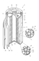
- a nickel-hydrogen secondary battery (hereinafter simply referred to as a battery) 2 according to the present invention will be described with reference to the drawings.
- the battery 2 to which the present invention is applied is not particularly limited.
- a case where the present invention is applied to an AA-sized cylindrical battery 2 shown in FIG. 1 will be described as an example.
- the battery 2 includes an outer can 10 having a bottomed cylindrical shape with an open top.
- the outer can 10 has conductivity, and its bottom wall 35 functions as a negative electrode terminal.
- a disc-shaped cover plate 14 having conductivity and a ring-shaped insulating packing 12 surrounding the cover plate 14 are arranged.
- the insulating packing 12 caulks the opening edge 37 of the outer can 10. It is fixed to the opening edge 37 of the outer can 10 by processing. That is, the lid plate 14 and the insulating packing 12 cooperate with each other to airtightly close the opening of the outer can 10.
- the lid plate 14 has a central through hole 16 in the center, and a rubber valve body 18 for closing the central through hole 16 is disposed on the outer surface of the lid plate 14. Further, a flanged cylindrical positive terminal 20 is fixed on the outer surface of the cover plate 14 so as to cover the valve body 18, and the positive terminal 20 presses the valve body 18 toward the cover plate 14.
- the positive electrode terminal 20 has a gas vent hole (not shown).
- the central through hole 16 is airtightly closed by the valve body 18.
- the valve body 18 is compressed by the internal pressure and opens the central through hole 16.
- the central through hole 16 and the positive electrode terminal 20 are opened from the outer can 10. Gas is released to the outside through the vent holes. That is, the central through hole 16, the valve body 18, and the positive electrode terminal 20 form a safety valve for the battery.
- the outer can 10 accommodates an electrode group 22.
- Each of the electrode groups 22 includes a strip-like positive electrode 24, a negative electrode 26, and a separator 28, which are wound in a spiral shape with the separator 28 sandwiched between the positive electrode 24 and the negative electrode 26. That is, the positive electrode 24 and the negative electrode 26 are overlapped with each other via the separator 28.
- the outermost periphery of the electrode group 22 is formed by a part of the negative electrode 26 (the outermost periphery) and is in contact with the inner peripheral wall of the outer can 10. That is, the negative electrode 26 and the outer can 10 are electrically connected to each other.
- a positive electrode lead 30 is disposed between one end of the electrode group 22 and the cover plate 14. Specifically, the positive electrode lead 30 has one end connected to the positive electrode 24 and the other end connected to the lid plate 14. Therefore, the positive electrode terminal 20 and the positive electrode 24 are electrically connected to each other via the positive electrode lead 30 and the cover plate 14.
- a circular insulating member 32 is disposed between the cover plate 14 and the electrode group 22, and the positive electrode lead 30 extends through a slit 39 provided in the insulating member 32.
- a circular insulating member 34 is also disposed between the electrode group 22 and the bottom of the outer can 10.
- alkaline electrolyte (not shown) is injected into the outer can 10.
- the alkaline electrolyte is impregnated in the electrode group 22 to advance a charge / discharge reaction between the positive electrode 24 and the negative electrode 26.
- the alkaline electrolyte include sodium hydroxide aqueous solution, lithium hydroxide aqueous solution, potassium hydroxide aqueous solution, and an aqueous solution obtained by mixing two or more of these.
- the alkaline electrolyte contains an LiOH.
- the separator 28 functions to prevent a short circuit between the positive electrode 24 and the negative electrode 26 and to hold an alkaline electrolyte.
- a polyamide fiber nonwoven fabric or a polyolefin fiber nonwoven fabric such as polyethylene or polypropylene provided with a hydrophilic functional group can be used.
- the sulfone group is imparted by treating the nonwoven fabric with an acid containing a sulfuric acid group such as sulfuric acid or fuming sulfuric acid.
- a battery using a separator including such a fiber having a sulfone group exhibits excellent self-discharge characteristics.
- the positive electrode 24 is composed of a conductive positive electrode base material having a porous structure and a positive electrode mixture held in the pores of the positive electrode base material.
- a positive electrode substrate for example, a net-like, sponge-like or fibrous metal body plated with nickel, or foamed nickel (nickel foam) can be used.
- the positive electrode mixture includes positive electrode active material particles 36 and a binder 42 as schematically shown in a circle S in FIG.
- the binder 42 serves to bind the positive electrode active material particles 36 to each other and simultaneously bind the positive electrode mixture to the positive electrode base material.
- the binder 42 for example, carboxymethylcellulose, methylcellulose, PTFE (polytetrafluoroethylene) dispersion, HPC (hydroxypropylcellulose) dispersion, and the like can be used.
- the positive electrode active material particles 36 described above have base particles 38 and a conductive layer 40 that covers the surfaces of the base particles 38.
- the base particles 38 are nickel hydroxide particles or higher-order nickel hydroxide particles.
- the average particle diameter of the base particles 38 is preferably set in the range of 8 ⁇ m to 20 ⁇ m. That is, in the non-sintered positive electrode, by increasing the surface area of the positive electrode active material, the electrode reaction area of the positive electrode can be increased and the output of the battery can be increased.
- the base particles 38 are preferably small particles having an average particle diameter of 20 ⁇ m or less. However, if the thickness of the conductive layer 40 deposited on the surface of the base particles is constant, the proportion of the conductive layer 40 increases as the diameter of the base particles 38 is reduced, resulting in a disadvantage that the unit capacity is reduced.
- the particle size is preferably 8 ⁇ m or more. A more preferable range is 10 ⁇ m to 16 ⁇ m.
- cobalt improves the conductivity inside the positive electrode active material particles and contributes to the improvement of the high rate discharge characteristics of the battery, and zinc suppresses the expansion of the positive electrode with the progress of the charge / discharge cycle, and the battery cycle. Contributes to improved life characteristics.
- the content of the element dissolved in the nickel hydroxide particles is 0.5 to 6.0 mass% for cobalt and 1.0 to 7.0 mass% for zinc with respect to nickel hydroxide. It is preferable to do. More preferably, the cobalt content is 0.7 to 2.0 mass% and the zinc content is 2.0 to 5.0 mass%.
- the base particles 38 can be manufactured as follows, for example. First, an aqueous solution of nickel sulfate is prepared. Base particles 38 made of nickel hydroxide are precipitated by gradually adding a sodium hydroxide aqueous solution to the nickel sulfate aqueous solution to cause a reaction. Here, when zinc and cobalt are dissolved in nickel hydroxide particles, nickel sulfate, zinc sulfate and cobalt sulfate are weighed so as to have a predetermined composition, and a mixed aqueous solution thereof is prepared.
- a sodium hydroxide aqueous solution is gradually added to the mixed aqueous solution to cause reaction, thereby precipitating base particles 38 mainly composed of nickel hydroxide and containing zinc and cobalt as a solid solution.
- the conductive layer 40 is made of a cobalt compound containing lithium (hereinafter referred to as a lithium-containing cobalt compound).
- a lithium-containing cobalt compound is a compound in which lithium is incorporated into a crystal of a cobalt compound such as cobalt oxyhydroxide (CoOOH) or cobalt hydroxide (Co (OH) 2 ). Since this lithium-containing cobalt compound has extremely high conductivity, it forms a good conductive network capable of increasing the utilization factor of the active material in the positive electrode.
- the conductive layer 40 is formed by the following procedure. First, base particles 38 are put into an aqueous ammonia solution, and an aqueous cobalt sulfate solution is added to this aqueous solution. Thereby, with the base particles 38 as nuclei, cobalt hydroxide is deposited on the surface of the nuclei, and intermediate particles having a cobalt hydroxide layer are formed. The obtained intermediate particles are convected in air containing oxygen in a high-temperature environment, and are subjected to heat treatment at a predetermined heating temperature and a predetermined heating time while being sprayed with a lithium hydroxide aqueous solution. Here, the heat treatment is preferably held at 80 to 100 ° C. for 30 minutes to 2 hours.
- the cobalt hydroxide on the surface of the intermediate particles becomes a highly conductive cobalt compound (such as cobalt oxyhydroxide) and takes in lithium.
- the positive electrode active material particle 36 covered with the conductive layer 40 made of a cobalt compound containing lithium is obtained.
- the cobalt compound it is preferable to further add sodium to the cobalt compound as the conductive layer 40 because the stability of the conductive layer is increased.
- a heat treatment is performed by spraying a sodium hydroxide aqueous solution together with a lithium hydroxide aqueous solution onto the intermediate particles convected in the air in a high temperature environment. Thereby, the positive electrode active material particles 36 covered with the conductive layer 40 made of a cobalt compound containing lithium and sodium are obtained.
- the positive electrode 24 can be manufactured as follows, for example. First, a positive electrode mixture paste containing the positive electrode active material particles 36 obtained as described above, water, and a binder 42 is prepared. The positive electrode mixture paste is filled in, for example, a sponge-like metal body (nickel foam) and dried. After drying, the nickel foam filled with nickel hydroxide particles and the like is roll-rolled and then cut to produce the positive electrode 24.
- a positive electrode mixture paste containing the positive electrode active material particles 36 obtained as described above, water, and a binder 42 is prepared.
- the positive electrode mixture paste is filled in, for example, a sponge-like metal body (nickel foam) and dried. After drying, the nickel foam filled with nickel hydroxide particles and the like is roll-rolled and then cut to produce the positive electrode 24.
- the positive electrode active material particles 36 composed of the base particles 38 whose surfaces are covered with the conductive layer 40 are in contact with each other.
- a conductive network is formed by the conductive layer 40.
- a Y compound is, for example, yttrium oxide
- the Nb compound is, for example, niobium oxide
- the Yb compound is, for example, ytterbium oxide
- the W compound is, for example, tungsten oxide. preferable.
- This additive is added to the positive electrode mixture, and the content thereof is preferably set in a range of 0.2 to 2 parts by mass with respect to 100 parts by mass of the positive electrode active material particles. This is because when the content of the additive is less than 0.2 parts by mass, the effect of suppressing the elution of cobalt from the conductive layer is small, and when the content exceeds 2 parts by mass, the effect is saturated and the positive electrode active material This is because the amount of is relatively lowered and the capacity is reduced.
- the total amount of Li contained in the battery is specified.
- the present inventor not only in the conductive layer of the positive electrode active material particles, but also in other places in the nickel metal hydride secondary battery, for example, in the positive electrode mixture, in the negative electrode mixture, the separator, the alkaline electrolyte, etc. If Li is present, it is possible to suppress the Li from reaching the conductive layer of the positive electrode active material particles via the alkaline electrolyte, and the dissolution of cobalt from the conductive layer of the positive electrode active material particles to destroy the conductive network. We found out that it was possible to identify the proper amount of Li in the battery. Hereinafter, such Li will be described in detail.
- the upper limit is set to 50 mg / Ah.
- the range of the total amount W of Li is 40 mg / Ah ⁇ W ⁇ 50 mg / Ah.
- a method for causing Li to exist in the form of LiOH in the battery As a method for causing Li to exist in the form of LiOH in the battery, a method of spraying an aqueous solution of LiOH on the positive electrode active material particles, a method of adding LiOH to the alkaline electrolyte, and LiOH in the positive electrode mixture paste , A method of supporting LiOH on the separator, a method of treating the hydrogen storage alloy of the negative electrode with LiOH, and the like, and these methods are preferably employed alone or in combination.
- the method of performing the treatment of spraying an aqueous solution of LiOH on the positive electrode active material particles as in the above-described embodiment is preferable because the treatment for unevenly distributing Li to the positive electrode can be easily performed.
- adopted for alkaline electrolyte it is preferable that the composition of alkaline electrolyte be a composition close
- the negative electrode 26 has a conductive negative electrode substrate (core body) having a strip shape, and a negative electrode mixture is held on the negative electrode substrate.
- the negative electrode substrate is made of a sheet-like metal material in which through holes are distributed. For example, a punched metal sheet or a sintered substrate obtained by molding and sintering metal powder can be used.
- the negative electrode mixture is not only filled in the through holes of the negative electrode substrate, but also held in layers on both surfaces of the negative electrode substrate.
- the negative electrode mixture is schematically shown in a circle R in FIG. 1, and includes hydrogen storage alloy particles 44, a conductive additive 46, and a binder 48.
- the binder 48 serves to bind the hydrogen storage alloy particles 44 and the conductive additive 46 to each other and at the same time bind the negative electrode mixture to the negative electrode substrate.
- the hydrogen storage alloy is an alloy capable of storing and releasing hydrogen which is a negative electrode active material.
- a hydrophilic or hydrophobic polymer or the like can be used, and as the conductive auxiliary agent 46, carbon black or graphite can be used.
- the rare earth-Mg—Ni-based hydrogen storage alloy preferably has an aspect having a composition represented by the following general formula (I).
- Ln 1-x Mg x (Ni 1-y T y ) z (I)
- Ln is La, Ce, Pr, Nd, Pm, Sm, Eu, Gd, Tb, Dy, Ho, Er, Tm, Yb, Lu, Ca, Sr, Sc, Y, Y represents at least one element selected from Yb, Ti, Zr and Hf
- T represents Mn, Co, V, Nb, Ta, Cr, Mo, Fe, Al, Ga, Zn, Sn, In, Cu, Si
- the hydrogen storage alloy according to the present invention is an A formed by laminating AB 2 type subunit and AB 5 type subunit when Ln and Mg in the general formula (I) are used as A component and Ni and T are used as B component. It has a so-called superlattice structure having a 2 B 7 type structure or an A 5 B 19 type structure. Hydrogen hydrogen storage alloy of a rare earth -Mg-Ni system which forms such a superlattice structure, and advantages of occluding and releasing hydrogen, which is a feature of the AB 5 type alloy is stable, which is characteristic of AB 2 type alloy It has the advantage of having a large amount of occlusion. For this reason, since the hydrogen storage alloy which concerns on this invention is excellent in hydrogen storage capacity, it contributes to high capacity
- the present inventor used these hydrogen storage alloys containing Mn and Co as the hydrogen storage alloy of the negative electrode. It has been found that components such as Mn and Co are eluted into the alkaline electrolyte and reach the surface of the positive electrode active material to reduce and elute cobalt oxyhydroxide and the like of the conductive network. Therefore, it is more preferable to employ a rare earth-Mg—Ni-based hydrogen storage alloy having a composition excluding Mn and Co as the hydrogen storage alloy of the present invention in order not to inhibit the conductivity in the battery.
- the hydrogen storage alloy particles 44 used in the present invention have a rare earth hydroxide 50 which is a rare earth element hydroxide on the surface thereof.
- the rare earth hydroxide 50 is formed by performing a so-called alkali treatment in which the hydrogen storage alloy particles 44 are immersed in an alkaline aqueous solution.
- the rare earth hydroxide 50 is precipitated as acicular crystals and forms irregularities on the surfaces of the hydrogen storage alloy particles 44.
- the rare earth hydroxide 50 functions to prevent the hydrogen storage alloy from being corroded by the alkaline electrolyte. That is, the presence of the rare earth hydroxide 50 on the surface of the hydrogen storage alloy makes it possible to reduce the amount of alkaline electrolyte consumed in the corrosion reaction of the hydrogen storage alloy. Thus, if the amount of alkaline electrolyte in the battery does not decrease, even if the alkaline electrolyte is taken into the positive electrode, the alkaline electrolyte is sufficiently retained in the separator, so that the internal resistance value of the battery increases. Can be suppressed. As a result, it contributes to improvement of the high rate discharge characteristics of the battery. Further, since the heat generation of the battery is suppressed by reducing the internal resistance value of the battery, the progress of the corrosion reaction of the hydrogen storage alloy is slowed down, and the consumption of the alkaline electrolyte accompanying the corrosion reaction is further reduced.
- the rare earth hydroxide 50 described above is non-conductive, if the amount of the rare earth hydroxide 50 is excessive on the surface of the hydrogen storage alloy particles 44, the charge / discharge reaction is hindered. On the other hand, if the amount of the rare earth hydroxide 50 is too small, the above-described effect is reduced. For this reason, it is preferable that the amount of the rare earth hydroxide 50 be in an appropriate range.
- the amount of the rare earth hydroxide 50 is proportional to the degree of unevenness on the surface of the hydrogen storage alloy particles 44. Therefore, the degree of the unevenness is obtained as the specific surface area of the hydrogen storage alloy particles 44, and the amount of the rare earth hydroxide 50 on the surface of the hydrogen storage alloy particles 44 is determined from the specific surface area. Control the amount.
- the specific surface area of the hydrogen storage alloy particles 44 is less than 0.1 m 2 / g, the amount of the rare earth hydroxide 50 on the surface of the hydrogen storage alloy particles 44 is small and the above-described effects cannot be obtained sufficiently.
- the specific surface area of the hydrogen storage alloy particles 44 exceeds 0.5 m 2 / g, the amount of the rare earth hydroxide 50 on the surface of the hydrogen storage alloy particles 44 increases, and the conductivity of the negative electrode containing the hydrogen storage alloy 44 is increased. Decreases and the charge / discharge reaction of the battery is inhibited. Therefore, the specific surface area of the hydrogen storage alloy particles 44 is preferably in the range of 0.1 to 0.5 m 2 / g.
- the hydrogen storage alloy particles 44 are obtained as follows, for example. First, metal raw materials are weighed and mixed so as to have a predetermined composition, and this mixture is melted in, for example, an induction melting furnace to form an ingot. The obtained ingot is subjected to heat treatment by heating in an inert gas atmosphere at 900 to 1200 ° C. for 5 to 24 hours. Thereafter, the ingot is pulverized and sieved to obtain an intermediate product of hydrogen storage alloy particles having a desired particle size. Next, the obtained intermediate product is subjected to an alkali treatment in which it is immersed in an aqueous alkali solution at a predetermined temperature for a predetermined time.
- the type and normality of the alkaline aqueous solution to be used are not particularly limited.
- a 5 to 9N potassium hydroxide aqueous solution is preferably used.
- the temperature of the aqueous alkali solution is preferably set to 60 to 100 ° C., and the treatment time is preferably set to 0.5 to 2.0 hours.
- the specific surface area of the hydrogen storage alloy particles subjected to such alkali treatment is measured, it is in the range of 0.1 to 0.5 m 2 / g.
- the hydrogen storage alloy particles 44 in which a suitable amount of acicular crystals of the rare earth hydroxide 50 are deposited on the surface can be obtained.
- the negative electrode 26 can be manufactured as follows, for example. First, a negative electrode mixture paste obtained by kneading a hydrogen storage alloy powder composed of hydrogen storage alloy particles 44 having a rare earth hydroxide 50 on the surface after the alkali treatment as described above, a conductive auxiliary agent 46, a binder 48 and water. To prepare. The obtained negative electrode mixture paste is applied to the negative electrode substrate and dried. After drying, the negative electrode substrate to which the hydrogen storage alloy particles 44 and the like are attached is subjected to roll rolling and cutting, whereby the negative electrode 26 is produced.
- the positive electrode 24 and the negative electrode 26 produced as described above are spirally wound with a separator 28 interposed therebetween. Thereby, the electrode group 22 is formed.
- the electrode group 22 thus obtained is accommodated in the outer can 10. Subsequently, a predetermined amount of alkaline electrolyte is injected into the outer can 10. Thereafter, the outer can 10 containing the electrode group 22 and the alkaline electrolyte is sealed by the cover plate 14 provided with the positive electrode terminal 20, and the battery 2 according to the present invention is obtained.
- the battery 2 of the present invention has a configuration for specifying the total amount of Li contained in the battery 2, and a configuration for depositing the rare earth hydroxide 50 on the surface of the hydrogen storage alloy particles 44 contained in the negative electrode 26. Is characterized by the combination.
- the battery 2 of the present invention can suppress the destruction of the conductive network and extend the cycle life.
- the rare earth hydroxide 50 is deposited on the surface of the hydrogen storage alloy particles 44, and the amount of the precipitation is controlled, thereby suppressing the corrosion reaction of the hydrogen storage alloy and reducing the consumption of the alkaline electrolyte.
- the alkaline electrolyte in the separator can be prevented from being depleted and an increase in the internal resistance value can be suppressed, so that the obtained battery can be discharged with a large current and the high rate discharge characteristics are improved. Therefore, the battery 2 of the present invention can achieve both cycle life characteristics and high rate discharge characteristics.
- Example 1 Manufacture of batteries (1) Preparation of positive electrode Nickel sulfate, zinc sulfate, and cobalt sulfate were weighed so that they were 3% by mass of zinc and 1% by mass of cobalt with respect to nickel. In addition to the aqueous sodium solution, a mixed aqueous solution was prepared. While stirring the obtained mixed aqueous solution, a 10N aqueous sodium hydroxide solution was gradually added to the mixed aqueous solution to cause a reaction. During the reaction, the pH was stabilized at 13 to 14 and nickel hydroxide was mainly used. Thus, base particles 38 in which zinc and cobalt are dissolved are produced.
- the obtained base particles 38 were washed three times with 10 times the amount of pure water, then dehydrated and dried.
- the obtained base particles 38 have a spherical shape with an average particle diameter of 10 ⁇ m.
- the obtained base particles 38 were put into an aqueous ammonia solution, and an aqueous cobalt sulfate solution was added while maintaining the pH during the reaction at 9-10. Thereby, with the base particles 38 as nuclei, cobalt hydroxide was precipitated on the surfaces of the nuclei, and intermediate particles having a cobalt hydroxide layer having a thickness of about 0.1 ⁇ m were obtained. Subsequently, the intermediate particles were convected in a high-temperature air containing oxygen in an environment of 80 ° C., sprayed with a 12N aqueous sodium hydroxide solution and a 4N lithium hydroxide aqueous solution, and subjected to a heat treatment for 45 minutes. .
- cobalt hydroxide on the surface of the intermediate particles becomes highly conductive cobalt oxyhydroxide, and sodium and lithium are incorporated into the cobalt oxyhydroxide layer, and the cobalt compound contains sodium and lithium.
- a conductive layer 40 made of is formed. Thereafter, the particles having the cobalt oxyhydroxide layer were collected by filtration, washed with water, and dried at 60 ° C. In this manner, positive electrode active material particles 36 having conductive layers 40 made of cobalt oxyhydroxide containing sodium and lithium on the surfaces of the base particles 38 were obtained.
- the positive electrode active material paste in the obtained positive electrode has positive electrode active material particles 36 composed of base particles 38 whose surfaces are covered with a conductive layer 40 in contact with each other.
- the conductive layer 40 forms a conductive network.
- the filling amount of the positive electrode 24 is adjusted so that the capacity per one positive electrode is 2500 mAh from the theoretical capacity of nickel hydroxide of 289 mAh / g.
- the composition of (La 0.25 Sm 0.73 Zr 0.02) 0.90 Mg 0.10 Ni An ingot of a hydrogen storage alloy having 3.20 Al 0.20 was obtained. Thereafter, the ingot was mechanically pulverized in an argon gas atmosphere and sieved to select a powder composed of hydrogen storage alloy particles remaining between 400 mesh and 200 mesh.
- the hydrogen storage alloy particles had an average particle size of 30 ⁇ m corresponding to an integrated value of 50% and a maximum particle size of 45 ⁇ m. Met.
- a 7N aqueous potassium hydroxide solution was prepared, and the aqueous potassium hydroxide solution was heated to 80 ° C.
- the particles of the hydrogen storage alloy described above were immersed in this aqueous potassium hydroxide solution and held for 1 hour, whereby the hydrogen storage alloy particles were subjected to an alkali treatment to form a rare earth hydroxide on the particle surface.
- the rare earth hydroxide formed at this time was confirmed to be a rare earth hydroxide by X-ray diffraction measurement (XRD measurement).
- the rare earth hydroxide is considered to be La and Sm hydroxide from the rare earth element components contained in the hydrogen storage alloy used in this example.
- the alkali-treated hydrogen storage alloy particles were washed with water and dried to obtain alkali-treated hydrogen storage alloy particles. It was 0.4 m ⁇ 2 > / g when the specific surface area of this alkali-treated hydrogen storage alloy particle was measured by the nitrogen gas adsorption
- the paste of the negative electrode mixture was applied to both surfaces of an iron perforated plate as a negative electrode substrate so that the thickness was uniform and constant. At this time, the paste of the negative electrode mixture is also filled in the through holes of the perforated plate.
- This perforated plate has a thickness of 60 ⁇ m, and its surface is plated with nickel.
- the perforated plate to which the hydrogen storage alloy powder or the like adhered was further rolled and then cut to prepare an AA size negative electrode 26 containing the hydrogen storage alloy.
- the filling amount of the negative electrode 26 is adjusted so that the capacity per negative electrode is 3500 mAh.
- the capacity of the negative electrode is adjusted by assuming that the capacity of 1 g of the hydrogen storage alloy is 350 mAh and setting the amount of the hydrogen storage alloy to 10.0 g.
- the obtained positive electrode 24 and negative electrode 26 were spirally wound with a separator 28 sandwiched between them, and an electrode group 22 was produced.
- the separator 28 used for production of the electrode group 22 here was made of a nonwoven fabric made of polypropylene fiber, and its thickness was 0.1 mm (weight per unit area: 40 g / m 2 ).
- the electrode group 22 was housed in a bottomed cylindrical outer can 10 and a predetermined amount of a 30% by mass sodium hydroxide aqueous solution containing lithium, potassium, and sodium was injected as an alkaline electrolyte.
- KOH was 5.0N
- NaOH was 3.0N
- LiOH was 0.7N.
- the opening of the outer can 10 was closed with a cover plate 14 or the like, and an AA size nickel-hydrogen secondary battery 2 having a positive electrode capacity of 2500 mAh was assembled. Since this battery is a positive electrode-regulated battery whose negative electrode capacity is larger than the positive electrode capacity, the positive electrode capacity of 2500 mAh was used as the nominal capacity of the battery.
- the amount of LiOH contained in the battery was measured as follows. First, the whole battery was dissolved using concentrated nitric acid to obtain a solution, and then hydrogen peroxide solution was injected into the solution to neutralize the solution. Thereafter, the amount of Li contained in the neutralized solution was measured using an atomic absorption method, and this value was converted to the amount of LiOH.
- Example 2 The particles of the hydrogen storage alloy appropriately modified time of immersion in an aqueous solution of potassium hydroxide, except that the 0.1m 2 /g,0.5m 2 / g specific surface area of the particles of the hydrogen storage alloy, Example 1 A nickel metal hydride secondary battery was obtained in the same manner as the battery.
- Example 5 (Examples 4 to 5) Implementation was performed except that the concentration of the lithium hydroxide aqueous solution sprayed on the intermediate particles used for the positive electrode was appropriately changed, and the mass of LiOH per unit capacity of the positive electrode contained in the battery was 15 mg / Ah and 50 mg / Ah.
- a nickel metal hydride secondary battery was obtained in the same manner as the battery of Example 1.
- Example 6 Except that the composition of the hydrogen storage alloy was (La 0.25 Sm 0.73 Zr 0.02 ) 0.90 Mg 0.10 Ni 3.00 Al 0.20 Mn 0.10 Co 0.10 A nickel metal hydride secondary battery was obtained in the same manner as the battery of Example 1.
- Example 7 The battery of Example 1 was used except that the composition of the hydrogen storage alloy was (La 0.10 Sm 0.88 Zr 0.02 ) 0.90 Mg 0.10 Ni 3.20 Al 0.20. A nickel metal hydride secondary battery was obtained.
- Example 8 The battery of Example 1 was used except that the composition of the hydrogen storage alloy was (La 0.88 Sm 0.10 Zr 0.02 ) 0.90 Mg 0.10 Ni 3.20 Al 0.20. A nickel metal hydride secondary battery was obtained.
- Example 9 When producing the positive electrode, a nickel-hydrogen secondary battery similar to the battery of Example 1 was obtained except that 0.3 parts by mass of niobium oxide powder was further added to the positive electrode mixture paste as an additive.
- Example 10 When producing the positive electrode, a nickel-hydrogen secondary battery similar to the battery of Example 1 was obtained except that 0.3 parts by mass of ytterbium oxide powder was further added as an additive to the positive electrode mixture paste.
- Example 11 When producing the positive electrode, a nickel-hydrogen secondary battery similar to the battery of Example 1 was obtained except that 0.3 parts by mass of tungsten oxide powder was further added as an additive to the positive electrode mixture paste.
- Example 1 When producing the positive electrode, the concentration of the lithium hydroxide aqueous solution sprayed on the intermediate particles was changed as appropriate so that the mass of LiOH per unit capacity of the positive electrode was 12 mg / Ah, and the hydrogen storage alloy particles were hydroxylated.
- a nickel metal hydride secondary battery was obtained in the same manner as the battery of Example 1 except that it was not immersed in an aqueous potassium solution and not subjected to alkali treatment.
- Example 2 A nickel metal hydride secondary battery was obtained in the same manner as the battery of Example 1 except that the hydrogen storage alloy particles were not immersed in an aqueous potassium hydroxide solution and not subjected to alkali treatment.
- Nickel metal hydride secondary battery in the same manner as the battery of Example 1, except that the composition of the hydrogen storage alloy was La 0.70 Ce 0.30 Ni 3.80 Al 0.30 Mn 0.40 Co 0.50 Got.
- the batteries of Examples 1 to 11 and Comparative Examples 1 to 6 were charged for 1 hour at a charging current of 1.0 C under an environment of 25 ° C., and then 4.0 C under an environment of 25 ° C.
- the discharge capacity of the battery was measured when the battery was discharged until the final discharge voltage reached 0.8 V with a discharge current of.
- the discharge capacity at this time is 4.0C discharge capacity.
- discharge capacity ratio The value of the discharge capacity ratio of the battery of Comparative Example 1 was set to 100, and the ratio to the value of the discharge capacity ratio of each battery was determined. The results are also shown in the column of high rate discharge characteristics in Table 1.
- a battery having a higher value of the discharge capacity ratio is capable of discharging at a higher current, indicating that it is excellent in high rate discharge characteristics. That is, the higher the numerical value in the column of high rate discharge characteristics, the better the high rate discharge characteristics.
- the battery of Comparative Example 2 in which Li is contained in the positive electrode has cycle life characteristics.
- the high-rate discharge characteristics are decreased, and it is understood that these two characteristics are not compatible only by increasing the amount of Li. This is because if the positive electrode contains Li, the alkaline electrolyte is taken in between the nickel hydroxide crystals, and the amount of the alkaline electrolyte contained in the separator decreases, thereby increasing the value of the internal resistance of the entire battery. This is probably because of this.
- Example 1 in which Li was contained in the positive electrode and the hydrogen storage alloy particles were subjected to alkali treatment, the cycle life characteristics were further improved, and either the increase of Li to the positive electrode or the alkali treatment of the hydrogen storage alloy was performed.
- the high-rate discharge characteristics which had been reduced by the change, are greatly improved, and an unexpected effect is exhibited. This is because, even when an alkaline electrolyte is taken into the positive electrode, the corrosion resistance of the hydrogen storage alloy is improved and the corrosion reaction between the hydrogen storage alloy and the alkaline electrolyte is suppressed. It is considered that the increase in the internal resistance value of the entire battery was suppressed by being held by the separator.
- Example 1 From the results of Example 1 and Comparative Example 5, it can be seen that the hydrogen storage alloy can not be obtained effect of both cycle life characteristics and high-rate discharge characteristics is AB 5 system containing no Mg.
- the amount of La contained in the hydrogen storage alloy is preferably 20% by mass or more and the amount of Sm is preferably 20% by mass or more. This is considered to be because when the rare earth element reacts with the alkaline electrolyte, a hydroxide of the rare earth element is formed, but the reaction differs little by little depending on the element.
- the present invention achieves high efficiency by controlling the amount of Li in the nickel-hydrogen secondary battery and the specific surface area of the rare earth-Mg—Ni-based hydrogen storage alloy particles within a specific range.
- a nickel metal hydride secondary battery with improved discharge characteristics and cycle life characteristics can be provided, and its industrial value is extremely high.
- the nickel metal hydride secondary battery may be a prismatic battery and has a mechanical structure. Is not exceptionally limited.
- Nickel-hydrogen secondary battery 22 Nickel-hydrogen secondary battery 22 Electrode group 24 Positive electrode 26 Negative electrode 28 Separator 36 Positive electrode active material particle 44 Hydrogen storage alloy particle 50 Rare earth hydroxide
Landscapes
- Chemical & Material Sciences (AREA)
- Chemical Kinetics & Catalysis (AREA)
- Electrochemistry (AREA)
- General Chemical & Material Sciences (AREA)
- Engineering & Computer Science (AREA)
- Manufacturing & Machinery (AREA)
- Inorganic Chemistry (AREA)
- Battery Electrode And Active Subsutance (AREA)
- Secondary Cells (AREA)
Abstract
L'invention concerne une batterie rechargeable au nickel-hydrogène (2) qui comprend un groupe d'électrodes (22) ainsi qu'une solution électrolytique alcaline, ledit groupe d'électrodes (22) étant constitué d'une électrode positive (24) et d'une électrode négative (26), qui sont superposées l'une sur l'autre, un séparateur (28) étant intercalé entre celles-ci. Cette batterie (2) contient Li, et la quantité totale de Li dans la batterie (2) est de 15 à 50 mg/Ah, si elle est déterminée en tant que masse en termes de LiOH pour 1 Ah de la capacité de l'électrode positive. L'électrode négative (26) contient des particules d'un alliage de stockage d'hydrogène de système de terres rares-Mg-Ni qui contient un élément de terres rares, Mg et Ni. Chaque particule d'alliage de stockage d'hydrogène (44) a un hydroxyde de terres rares (50), qui est un hydroxyde de l'élément de terres rares, sur la surface, tout en ayant une surface spécifique de 0,1 à 0,5 m2/g.
Priority Applications (4)
| Application Number | Priority Date | Filing Date | Title |
|---|---|---|---|
| ES15812439T ES2773463T3 (es) | 2014-06-27 | 2015-06-23 | Batería secundaria de níquel-hidrógeno |
| CN201580034656.8A CN106463786B (zh) | 2014-06-27 | 2015-06-23 | 镍氢二次电池 |
| US15/317,106 US10693194B2 (en) | 2014-06-27 | 2015-06-23 | Nickel hydrogen secondary battery |
| EP15812439.6A EP3163668B1 (fr) | 2014-06-27 | 2015-06-23 | Batterie rechargeable au nickel-hydrogène |
Applications Claiming Priority (2)
| Application Number | Priority Date | Filing Date | Title |
|---|---|---|---|
| JP2014132777A JP6422111B2 (ja) | 2014-06-27 | 2014-06-27 | ニッケル水素二次電池 |
| JP2014-132777 | 2014-06-27 |
Publications (1)
| Publication Number | Publication Date |
|---|---|
| WO2015199072A1 true WO2015199072A1 (fr) | 2015-12-30 |
Family
ID=54938154
Family Applications (1)
| Application Number | Title | Priority Date | Filing Date |
|---|---|---|---|
| PCT/JP2015/068038 Ceased WO2015199072A1 (fr) | 2014-06-27 | 2015-06-23 | Batterie rechargeable au nickel-hydrogène |
Country Status (6)
| Country | Link |
|---|---|
| US (1) | US10693194B2 (fr) |
| EP (1) | EP3163668B1 (fr) |
| JP (1) | JP6422111B2 (fr) |
| CN (1) | CN106463786B (fr) |
| ES (1) | ES2773463T3 (fr) |
| WO (1) | WO2015199072A1 (fr) |
Cited By (1)
| Publication number | Priority date | Publication date | Assignee | Title |
|---|---|---|---|---|
| WO2020012809A1 (fr) * | 2018-07-11 | 2020-01-16 | 株式会社豊田自動織機 | Batterie au nickel-hydrure métallique |
Families Citing this family (5)
| Publication number | Priority date | Publication date | Assignee | Title |
|---|---|---|---|---|
| CN107958996B (zh) * | 2017-12-15 | 2020-10-27 | 四川大学 | 铁-储氢复合负电极、镍基蓄电池及其制备方法 |
| JP7129288B2 (ja) * | 2018-09-12 | 2022-09-01 | Fdk株式会社 | アルカリ二次電池用の正極及びこの正極を含むアルカリ二次電池 |
| CN115136351B (zh) * | 2020-02-21 | 2026-02-06 | Fdk株式会社 | 碱性二次电池用的镍电极及包含该镍电极的碱性二次电池 |
| CN111471913B (zh) * | 2020-04-14 | 2021-07-13 | 包头稀土研究院 | Ab3型稀土-钐-镍储氢合金、负极、电池及制备方法 |
| JP7684100B2 (ja) * | 2021-05-28 | 2025-05-27 | Fdk株式会社 | ニッケル水素二次電池 |
Citations (6)
| Publication number | Priority date | Publication date | Assignee | Title |
|---|---|---|---|---|
| JPH04137361A (ja) * | 1990-09-26 | 1992-05-12 | Matsushita Electric Ind Co Ltd | 密閉形ニッケル・水素蓄電池 |
| JP2000021398A (ja) * | 1998-07-01 | 2000-01-21 | Toshiba Battery Co Ltd | アルカリ二次電池 |
| JP2003217590A (ja) * | 2002-01-23 | 2003-07-31 | Yuasa Corp | ニッケル水素蓄電池およびその製造方法 |
| JP2013206866A (ja) * | 2012-03-29 | 2013-10-07 | Fdk Twicell Co Ltd | ニッケル水素二次電池 |
| JP2013251061A (ja) * | 2012-05-30 | 2013-12-12 | Fdk Twicell Co Ltd | アルカリ蓄電池 |
| JP2014089879A (ja) * | 2012-10-30 | 2014-05-15 | Fdk Twicell Co Ltd | ニッケル水素二次電池 |
Family Cites Families (15)
| Publication number | Priority date | Publication date | Assignee | Title |
|---|---|---|---|---|
| JP2978094B2 (ja) * | 1995-08-30 | 1999-11-15 | 古河電気工業株式会社 | 水素吸蔵合金粉末の表面処理方法とそれを適用して得られたアルカリ二次電池 |
| CN1205679C (zh) * | 1995-09-28 | 2005-06-08 | 株式会社汤浅 | 储氢电极、镍电极和碱性蓄电池 |
| JPH09204914A (ja) * | 1996-01-26 | 1997-08-05 | Yuasa Corp | 水素吸蔵電極 |
| KR19980033322A (ko) * | 1996-10-31 | 1998-07-25 | 가나가와지히로 | 수소흡장 합금 함유 조성물 및 그를 사용한 전극 |
| JP2953463B2 (ja) | 1997-09-10 | 1999-09-27 | 松下電器産業株式会社 | アルカリ蓄電池用正極活物質とその製造方法 |
| JP4020769B2 (ja) * | 2002-11-28 | 2007-12-12 | 三洋電機株式会社 | ニッケル水素二次電池 |
| JP4420641B2 (ja) * | 2003-09-18 | 2010-02-24 | 三洋電機株式会社 | アルカリ蓄電池用水素吸蔵合金及びアルカリ蓄電池 |
| US20070269717A1 (en) | 2004-08-26 | 2007-11-22 | Gs Yuasa Corporation | Hydrogen Absorbing Electrode and Nickel Metal-Hydridge Battery |
| CN101027802A (zh) * | 2004-08-26 | 2007-08-29 | 株式会社杰士汤浅 | 储氢电极及镍氢电池 |
| JP5119577B2 (ja) * | 2005-07-04 | 2013-01-16 | 株式会社Gsユアサ | ニッケル水素電池 |
| US8377555B2 (en) * | 2008-02-22 | 2013-02-19 | Toyota Motor Engineering & Manufacturing North America, Inc. | Gas storage materials, including hydrogen storage materials |
| JP4667513B2 (ja) * | 2008-05-30 | 2011-04-13 | パナソニック株式会社 | 水素吸蔵合金粉末とその表面処理方法、アルカリ蓄電池用負極、およびアルカリ蓄電池 |
| JP5733859B2 (ja) * | 2011-07-28 | 2015-06-10 | Fdk株式会社 | ニッケル水素二次電池 |
| CN103259003B (zh) * | 2012-02-20 | 2017-03-01 | 株式会社杰士汤浅国际 | 贮氢合金、电极、镍氢蓄电池及贮氢合金的制造方法 |
| JP5716969B2 (ja) * | 2012-09-27 | 2015-05-13 | 株式会社Gsユアサ | ニッケル水素蓄電池 |
-
2014
- 2014-06-27 JP JP2014132777A patent/JP6422111B2/ja active Active
-
2015
- 2015-06-23 ES ES15812439T patent/ES2773463T3/es active Active
- 2015-06-23 CN CN201580034656.8A patent/CN106463786B/zh active Active
- 2015-06-23 WO PCT/JP2015/068038 patent/WO2015199072A1/fr not_active Ceased
- 2015-06-23 EP EP15812439.6A patent/EP3163668B1/fr active Active
- 2015-06-23 US US15/317,106 patent/US10693194B2/en active Active
Patent Citations (6)
| Publication number | Priority date | Publication date | Assignee | Title |
|---|---|---|---|---|
| JPH04137361A (ja) * | 1990-09-26 | 1992-05-12 | Matsushita Electric Ind Co Ltd | 密閉形ニッケル・水素蓄電池 |
| JP2000021398A (ja) * | 1998-07-01 | 2000-01-21 | Toshiba Battery Co Ltd | アルカリ二次電池 |
| JP2003217590A (ja) * | 2002-01-23 | 2003-07-31 | Yuasa Corp | ニッケル水素蓄電池およびその製造方法 |
| JP2013206866A (ja) * | 2012-03-29 | 2013-10-07 | Fdk Twicell Co Ltd | ニッケル水素二次電池 |
| JP2013251061A (ja) * | 2012-05-30 | 2013-12-12 | Fdk Twicell Co Ltd | アルカリ蓄電池 |
| JP2014089879A (ja) * | 2012-10-30 | 2014-05-15 | Fdk Twicell Co Ltd | ニッケル水素二次電池 |
Non-Patent Citations (1)
| Title |
|---|
| See also references of EP3163668A4 * |
Cited By (1)
| Publication number | Priority date | Publication date | Assignee | Title |
|---|---|---|---|---|
| WO2020012809A1 (fr) * | 2018-07-11 | 2020-01-16 | 株式会社豊田自動織機 | Batterie au nickel-hydrure métallique |
Also Published As
| Publication number | Publication date |
|---|---|
| US10693194B2 (en) | 2020-06-23 |
| CN106463786A (zh) | 2017-02-22 |
| CN106463786B (zh) | 2020-04-21 |
| ES2773463T3 (es) | 2020-07-13 |
| JP6422111B2 (ja) | 2018-11-14 |
| US20170110764A1 (en) | 2017-04-20 |
| JP2016012443A (ja) | 2016-01-21 |
| EP3163668B1 (fr) | 2019-12-18 |
| EP3163668A1 (fr) | 2017-05-03 |
| EP3163668A4 (fr) | 2017-11-22 |
Similar Documents
| Publication | Publication Date | Title |
|---|---|---|
| JP5984287B2 (ja) | アルカリ蓄電池 | |
| JP6132279B2 (ja) | ニッケル水素二次電池 | |
| JP5733859B2 (ja) | ニッケル水素二次電池 | |
| JP6422111B2 (ja) | ニッケル水素二次電池 | |
| JP6112822B2 (ja) | ニッケル水素二次電池 | |
| JP5959003B2 (ja) | ニッケル水素二次電池及びニッケル水素二次電池用の負極 | |
| JP2016149299A (ja) | ニッケル水素二次電池 | |
| JP2007149647A (ja) | ニッケル水素蓄電池 | |
| JP6120362B2 (ja) | ニッケル水素二次電池用の負極及びこの負極を用いたニッケル水素二次電池 | |
| JP6573463B2 (ja) | 水素吸蔵合金粉末及びこの水素吸蔵合金粉末を用いたニッケル水素二次電池 | |
| JP6049048B2 (ja) | ニッケル水素二次電池 | |
| JP6057369B2 (ja) | ニッケル水素二次電池 | |
| JP6153156B2 (ja) | 水素吸蔵合金及びこの水素吸蔵合金を用いたニッケル水素二次電池 | |
| JP6573518B2 (ja) | アルカリ二次電池用の負極及びこの負極を用いたアルカリ二次電池 | |
| JP2017021896A (ja) | 水素吸蔵合金粉末の製造方法及びニッケル水素二次電池 | |
| JP2012074299A (ja) | ニッケル水素二次電池 | |
| WO2017169163A1 (fr) | Électrode négative pour pile alcaline rechargeable, et pile alcaline rechargeable comprenant l'électrode négative | |
| JP7128069B2 (ja) | アルカリ二次電池用の正極及びこの正極を備えたアルカリ二次電池 | |
| JPH11260360A (ja) | アルカリ蓄電池用正極及びアルカリ蓄電池 | |
| JP7125218B2 (ja) | アルカリ二次電池用の負極及びアルカリ二次電池 |
Legal Events
| Date | Code | Title | Description |
|---|---|---|---|
| 121 | Ep: the epo has been informed by wipo that ep was designated in this application |
Ref document number: 15812439 Country of ref document: EP Kind code of ref document: A1 |
|
| WWE | Wipo information: entry into national phase |
Ref document number: 15317106 Country of ref document: US |
|
| REEP | Request for entry into the european phase |
Ref document number: 2015812439 Country of ref document: EP |
|
| WWE | Wipo information: entry into national phase |
Ref document number: 2015812439 Country of ref document: EP |
|
| NENP | Non-entry into the national phase |
Ref country code: DE |