WO2016002008A1 - 空気調和システム - Google Patents
空気調和システム Download PDFInfo
- Publication number
- WO2016002008A1 WO2016002008A1 PCT/JP2014/067559 JP2014067559W WO2016002008A1 WO 2016002008 A1 WO2016002008 A1 WO 2016002008A1 JP 2014067559 W JP2014067559 W JP 2014067559W WO 2016002008 A1 WO2016002008 A1 WO 2016002008A1
- Authority
- WO
- WIPO (PCT)
- Prior art keywords
- outdoor unit
- operating frequency
- air conditioner
- compressor
- unit
- Prior art date
- Legal status (The legal status is an assumption and is not a legal conclusion. Google has not performed a legal analysis and makes no representation as to the accuracy of the status listed.)
- Ceased
Links
Images




Classifications
-
- F—MECHANICAL ENGINEERING; LIGHTING; HEATING; WEAPONS; BLASTING
- F24—HEATING; RANGES; VENTILATING
- F24F—AIR-CONDITIONING; AIR-HUMIDIFICATION; VENTILATION; USE OF AIR CURRENTS FOR SCREENING
- F24F11/00—Control or safety arrangements
- F24F11/89—Arrangement or mounting of control or safety devices
-
- F—MECHANICAL ENGINEERING; LIGHTING; HEATING; WEAPONS; BLASTING
- F25—REFRIGERATION OR COOLING; COMBINED HEATING AND REFRIGERATION SYSTEMS; HEAT PUMP SYSTEMS; MANUFACTURE OR STORAGE OF ICE; LIQUEFACTION SOLIDIFICATION OF GASES
- F25B—REFRIGERATION MACHINES, PLANTS OR SYSTEMS; COMBINED HEATING AND REFRIGERATION SYSTEMS; HEAT PUMP SYSTEMS
- F25B1/00—Compression machines, plants or systems with non-reversible cycle
Definitions
- the present invention relates to an air conditioning system and the like.
- the present invention relates to a system control device.
- an air conditioner having a compressor that can change the capacity by performing inverter control or the like and arbitrarily changing the operating frequency (driving frequency). Then, at a specific operating frequency, the relationship between the operating frequency and the efficiency at which the energy efficiency (hereinafter referred to as efficiency) related to the operation of the air conditioner represented by COP (Coefficient of Performance) etc. is maximized.
- efficiency energy efficiency
- COP Coefficient of Performance
- an operation at a specific operating frequency at which the efficiency in the efficiency curve characteristic has a maximum value is a basic state in the energy saving control time zone. If it is determined that the capacity is insufficient from the deviation between the set temperature of the space (air-conditioned space) to be air-conditioned and the room temperature, control is performed to increase the operating frequency of the air-conditioning apparatus and increase the cooling / heating capacity. By performing such control, a desired energy saving effect can be obtained while maintaining the comfort of the air-conditioned space (see, for example, Patent Document 1).
- the present invention has been made to solve such a conventional problem, and can efficiently perform air conditioning in an air-conditioned space without causing an excessive effect (excess supply of capacity) of the air conditioning apparatus.
- a control device for an air conditioning system is provided.
- the air conditioning system of the present invention includes one or a plurality of air conditioning systems having a refrigerant circuit configured by connecting an outdoor unit having a compressor capable of arbitrarily changing an operating frequency and an indoor unit performing air conditioning of a target space.
- a centralized control device having a control unit.
- the compressor that distributes the air conditioning load and is driven at an operation frequency lower than the maximum efficiency operation frequency can be driven at an operating frequency with the maximum efficiency or an operating frequency close thereto, and the air conditioning system as a whole can be operated efficiently. For this reason, energy saving etc. can be achieved.
- FIG. 1 and the following drawings the same reference numerals denote the same or corresponding parts, and are common to the whole text of the embodiments described below.
- the form of the component represented by the whole specification is an illustration to the last, Comprising: It does not limit to the form described in the specification.
- the combination of the components is not limited to the combination in each embodiment, and the components described in the other embodiments can be applied to another embodiment.
- the subscripts may be omitted.
- FIG. 1 is a diagram showing a configuration of an air conditioning system centering on a centralized control device 100 according to Embodiment 1 of the present invention.
- the number of air conditioner groups is not limited to eight, and can be increased or decreased in accordance with the size of the air-conditioned space. Since this embodiment is related to the control of the air conditioning system, FIG. 1 shows the connection relationship regarding the control (communication) system.
- Each air conditioner group 1 has at least one outdoor unit 10 and one indoor unit 20.
- the air conditioner group 1 is a control unit (control group) performed by the centralized control device 100, and performs air conditioning control for each air conditioner group 1.
- FIG. 2 is a diagram showing details of the configuration of the air-conditioning system according to Embodiment 1 of the present invention.
- each air conditioner group 1 of the present embodiment has one outdoor unit 10 and two indoor units 20.
- One outdoor unit 10 (10a to 10h) and two indoor units 20 (20a-1 to 20h-2) are connected by a refrigerant pipe (not shown) to constitute a refrigerant circuit.
- Air conditioning capacity (heat) is supplied by circulating the refrigerant in the refrigerant circuit, and air conditioning is performed by heating or cooling the air in the air-conditioned space.
- each air conditioner group 1 is composed of one outdoor unit 10 and two indoor units 20, but the number of outdoor units 10 and indoor units 20 is particularly limited. Not what you want. The number of outdoor units 10 and indoor units 20 in each air conditioner group 1 may not be the same.
- the outdoor unit 10 includes devices such as a compressor 12 and an outdoor heat exchanger (not shown), and transports the generated heat to the indoor unit 20 using a refrigerant.
- the outdoor unit control device 11 controls the outdoor unit 10.
- the outdoor unit control device 11 communicates with the central control device 100 and the indoor unit control device 21 included in the indoor unit 20, for example, data on the operating frequency of the compressor 12 and an operation state in a signal sent from the indoor unit 20.
- a signal including the data (control value data) is sent to the centralized control device 100.
- the indoor unit 20 includes devices such as an indoor heat exchanger and a throttle device (expansion valve), and heat-exchanges heat from the outdoor unit 10 with air in the air-conditioned space, and heats and cools the air for air conditioning. I do. Moreover, it has the indoor unit control apparatus 21 which controls the indoor unit 20 based on the instruction
- the temperature difference between the ambient temperature of the indoor unit 20 (the temperature of the area where the air conditioner group 1 air-conditions in the air-conditioned space; hereinafter referred to as room temperature) and the set temperature is controlled. Value.
- the data relating to the operation state in the signal sent from the indoor unit 20 is not limited.
- the central control device 100 of the air conditioning system controls the operation related to the air conditioning of each air conditioner group 1.
- the centralized control device 100 can increase or decrease the operating frequency of the compressor 12 included in the outdoor unit 10 of each air conditioner group 1 and instruct to stop the operation frequency. Thereby, the outdoor unit 10 (air conditioner group 1) can be stopped. Further, based on the operation information data obtained from the indoor unit 20, an instruction to change the set temperature or the like can be given. Moreover, the data in the signal sent regularly, for example from each air conditioner group 1 (outdoor unit 10) are processed, and the data of the operating frequency of the compressor 12 and a control value (the operation state in the indoor unit 20) are obtained. And based on the operating frequency etc.
- FIG. A certain compressor 12 is stopped and the driven compressor 12 is driven at an operating frequency at or near the maximum efficiency so that air conditioning in the air-conditioned space can be performed efficiently without causing excessive effects. To save energy.
- the centralized control device 100 includes a control unit 110 and a storage unit 120.
- the control unit 110 performs control processing based on data included in a signal from the outdoor unit control device 11 included in the outdoor unit 10 of each air conditioner group 1.
- the control unit 110 according to the present embodiment is configured by a microcomputer having a control processing unit such as a CPU (Central Processing Unit).
- the storage unit 120 stores the data on the operating frequency of the compressor 12 and the data related to the operation state included in the signal from the outdoor unit control device 11.
- efficiency curve characteristics indicating the relationship between the operating frequency and efficiency of the compressor 12 are previously stored as data.
- data of efficiency curve characteristics of each type is included.
- the control unit 110 implements control by executing processing based on program data.
- FIG. 3 is a diagram showing a flowchart relating to the control of the air-conditioned space performed by the centralized control device 100 according to the first embodiment of the present invention.
- the control unit 110 of the centralized control device 100 acquires data on the operating frequency and control value data of the compressor 12 included in the signal transmitted from each outdoor unit 10. (S2). Then, the obtained operating frequency data and control value data of each compressor 12 are stored in the storage unit 120 (S3).
- control part 110 determines whether the outdoor unit 10 (air conditioner group 1) is stopped based on the data memorize
- the contents of the outdoor unit stop determination process will be described later.
- the signal of a stop command is sent to the outdoor unit 10 which concerns on a stop, and stop control is performed (S6).
- control unit 110 when the control unit 110 performs stop control and a certain time elapses (S7), even if the operating frequency of the compressor 12 in each outdoor unit 10 changes based on the control value data, for example, in the conditioned space. It is determined whether or not air conditioning stability is maintained (S8). If it is determined that it is not maintained, the stop control is canceled, the operation of the outdoor unit 10 is restarted, and the operating frequency of the compressor 12 of each outdoor unit 10 is returned to before the stop control (S9).
- the control unit 110 performs the above process once, and even if the operating frequency of the compressor 12 cannot be brought close to the operating frequency at which maximum efficiency is achieved, the control unit 110 repeatedly performs the process to maintain air conditioning stability. Meanwhile, the compressor 12 being driven is controlled so as to approach the operating frequency at which the maximum efficiency is achieved.
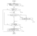
- FIG. 4 is a flowchart showing the compressor stop determination process according to the first embodiment of the present invention.
- the control unit 110 of the centralized control device 100 performs a compressor stop determination process for determining whether or not to stop the compressor 12.
- a detailed procedure of the compressor stop determination process will be described.
- the control unit 110 reads out the operation frequency data of the compressor 12 and the control value data of the indoor unit 20 included in the outdoor unit 10 in each air conditioner group 1 from the storage unit 120 (S11). Then, it is determined whether to stop the outdoor unit 10 (compressor 12) based on the read data and the data of the efficiency curve characteristic stored in the storage unit 120 (S12). If it is determined not to stop, the process ends.
- the air conditioner group 1a to the air conditioner group 1h perform the air conditioning of the assigned area, and perform the air conditioning of one air-conditioned space as a whole system. Therefore, the control unit 110 calculates the average capacity value (%) of the entire system.
- control unit 110 calculates an execution capacity value for each outdoor unit 10 (air conditioner group 1) based on the following equation (1).
- Effective capacity value rated capacity value of outdoor unit 10 x capacity saving rate (1)
- Average capacity value (total effective capacity value / total rated capacity value of each outdoor unit 10) ⁇ 100 ... (2)
- the controller 110 determines that the calculated average capacity value is higher than 40%, for example, it determines that the outdoor unit 10 (compressor 12) is not stopped. On the other hand, for example, if it is determined that it is 40% or less, it is determined that the efficiency of the entire system is low, and one of the outdoor units is determined to be stopped in order to increase the efficiency.
- the threshold value of the average ability value is set to 40%, but the present invention is not limited to this, and an arbitrary value can be set.
- the stop exclusion condition may be that the temperature difference indicated by the control value is greater than 3 ° C. In a state where the temperature difference between the set temperature and room temperature is large, it is necessary to continue air conditioning, and the outdoor unit 10 cannot be stopped. Further, for example, the occurrence of an abnormality in the outdoor unit 10 or the indoor unit 20 can be set as a stop exclusion condition. For the outdoor unit 10 (air conditioner group 1) determined to satisfy the condition, a process of removing it from the candidate for stop control is performed (S14).
- the outdoor is stopped from the outdoor units 10 (air conditioner group 1) that are candidates for stop control.
- the machine 10 is determined (S16).
- the control unit 110 determines that the outdoor unit 10 having the compressor 12 driven at the lowest operating frequency among the stop control target candidates is to be stopped.
- FIG. 5 is a diagram showing the relationship between the operating frequency and efficiency of the compressor 12 during the cooling operation according to Embodiment 1 of the present invention. During cooling operation, the efficiency increases slowly from a low operating frequency and slowly decreases even at an operating frequency higher than the maximum efficiency.
- FIG. 6 is a diagram showing the relationship between the operating frequency and efficiency of the compressor 12 during the heating operation according to Embodiment 1 of the present invention. During cooling operation, the maximum efficiency is obtained at an operating frequency lower than that during cooling operation.
- FIG. 7 is a diagram showing the relationship between the operating frequency and efficiency of the compressor 12 included in the outdoor unit 10 before the outdoor unit stop determination process according to Embodiment 1 of the present invention.
- the relationship with the efficiency in 1c (outdoor unit 10c) will be described.
- the operating frequency of the compressor 12 which each has in order of the outdoor unit 10a, the outdoor unit 10b, and the outdoor unit 10c becomes high.
- the operating frequency of the compressor 12 included in the outdoor unit 10a, the outdoor unit 10b, and the outdoor unit 10c is lower than the operating frequency at which the maximum efficiency is achieved.
- the operating frequency of the compressor 12a which the outdoor unit 10a has is the lowest, the outdoor unit 10a is stopped.
- FIG. 8 is a diagram showing the relationship between the operating frequency and efficiency of the compressor 12 when the compressor 12 included in one outdoor unit 10 according to Embodiment 1 of the present invention is stopped.
- the outdoor unit 10a receives the stop command signal
- the outdoor unit 10a stops the compressor 12.
- the operating frequency of the compressor 12 of the outdoor unit 10a is zero.
- the air-conditioning load which the outdoor unit 10a covered before the stop is distributed to the outdoor units 10b and 10c, and the air conditioner group 1b and the air conditioner group 1c perform the air conditioning of the air-conditioned space.
- the operating frequency of the compressor 12 in the outdoor unit 10b and the outdoor unit 10c shifts to a higher one.
- the operating frequency of the compressor 12 is lower than the operating frequency at which the maximum efficiency is achieved. Therefore, the outdoor unit 10b and 10c can be operated at a high operating frequency by shifting to a higher operating frequency.
- the central control device 100 determines the outdoor unit 10 to be stopped based on the operating state of each air conditioner group 1.
- the compressor 12 that is driven at an operating frequency lower than the maximum-efficiency operating frequency by distributing the load can be driven at an operating frequency close to the maximum-efficiency operating frequency, so that the entire air conditioning system is efficient. You can drive.
- FIG. 9 is a diagram showing a flowchart relating to the compressor stop determination process according to the second embodiment of the present invention.
- the same step numbers as those in FIG. 4 are the same as those described in the first embodiment.
- the outdoor unit 10 to be stopped may be biased depending on the state of heat load and the characteristics of the air-conditioned space. For this reason, a difference may arise in the operation time of each air conditioner group 1.
- the control unit 110 reads data from the storage unit 120 (S11), and determines that the outdoor unit 10 (compressor 12) is stopped (S12). The process of determining whether the accumulated operation time is less than the reference operation time is performed (S13A). Then, when it is determined that the accumulated operation time is less than the reference operation time, a process of removing from the operation stop target candidates is performed (S13). If it is determined that the accumulated operation time is not less than (or more than) the reference operation time, processing is performed to determine whether the operation state of the air conditioner group 1 satisfies the stop exclusion condition (S14). As a result, the air conditioner group 1 with a short accumulated operation time is excluded from the candidates for operation stop.
- the control unit 110 determines whether the integrated operation time of the air conditioner group 1 is equal to or longer than the reference operation time, and the air with a short integrated operation time. Since the conditioner group 1 is removed from the operation stop target, it is possible to prevent the outdoor operation unit 10 of the specific air conditioner group 1 from repeatedly stopping and the occurrence of bias in the accumulated operation time. For this reason, the operating time of each air conditioner group 1 can be leveled, and the air conditioning system reliability can be improved. Moreover, the lifetime of the outdoor unit 10 can be extended.
- Embodiment 3 FIG.
- the outdoor unit 10 having the compressor 12 having the lowest operating frequency among the stop control target candidates is stopped.
- the present invention is not limited to this.
- the outdoor unit 10 having the longest accumulated operation time among the stop control target candidates may be stopped.
- Air conditioner group 10,10a-10h outdoor unit 11,11a-11h outdoor unit control unit 12,12a-12h compressor, 20,20a-1-20h-2 indoor unit 21, 21a-1 to 21h-2, indoor unit control device, 100 central control device, 110 control unit, 120 storage unit.
Landscapes
- Engineering & Computer Science (AREA)
- Mechanical Engineering (AREA)
- General Engineering & Computer Science (AREA)
- Chemical & Material Sciences (AREA)
- Combustion & Propulsion (AREA)
- Physics & Mathematics (AREA)
- Thermal Sciences (AREA)
- Air Conditioning Control Device (AREA)
Abstract
本発明の空気調和システムは、動作周波数を任意に変化可能な圧縮機(12)を有する室外機(10)と対象空間の空気調和を行う室内機(20)とを配管接続して構成した冷媒回路を有する1又は複数の空気調和機グループ(1)と、各空気調和機グループ(1)における室外機(10)が有する圧縮機(12)の動作周波数をデータとして記憶する記憶部(120)及び各空気調和機グループ(1)の室外機(10)が有する圧縮機(12)の動作周波数とエネルギー効率との関係と記憶部(120)が記憶するデータとに基づいて、運転する空気調和機グループ(1)の室外機(10)が有する圧縮機(12)が、最大効率となる動作周波数に近づくように、停止する室外機(10)を決定する室外機停止判定処理を行う制御部(110)を有する集中制御機器(100)とを備えるものである。 上記構成により、集中制御機器の制御部が、停止する室外機を決定するようにしたので、空調負荷を分散させて、最大効率の動作周波数よりも低い動作周波数で駆動している圧縮機を、最大効率の動作周波数又はそれに近い動作周波数で駆動させることができ、空気調和システム全体として効率のよい運転を行うことができる。
Description
本発明は、空気調和システム等に関するものである。特にシステムの制御装置等に係るものである。
例えば、インバータ制御等を行い、動作周波数(駆動周波数)を任意に変化させることにより容量を変化させることができる圧縮機を有する空気調和装置がある。そして、特定の動作周波数で、COP(成績係数:Coefficient Of Performance)等で表される空気調和装置の運転に係るエネルギー効率(以下、効率という)が最大値となる動作周波数と効率との関係を示す効率曲線特性と、動作周波数の増大とともに空調能力が増加する関係を示す能力曲線とを有し、これらの特性に基づく制御を行う空気調和システムがある。
このような空気調和システムにおいて、省エネルギー制御時間帯において、効率曲線特性における効率が最大値を示す特定の動作周波数での運転を基本的状態とするものがある。そして、空気調和を行う対象となる空間(空調空間)の設定温度と室温の偏差から能力不足であるものと判断すると、空気調和装置の動作周波数を増加させて冷暖房能力を高める制御を行う。このような制御を行うことで、空調空間の快適性を維持しながら、所望の省エネルギー効果を得ることができるようにしている(例えば、特許文献1参照)。
しかしながら、特許文献1に記載のような従来の空気調和システムにおいて、例えば、春季、秋季のように、空気調和装置の能力が不足しない期間において、基本的状態である効率最大条件下での運転を行うと能力過剰となる可能性がある。このため、空気調和の効き過ぎが起こる可能性が高くなる。また、全体的に空気調和システムの能力が不足する空調空間を前提とした制御を行っているため、空気調和装置の能力が十分に高い、夏季又は冬季でも比較的空調負荷が低い空間等の場合においては、条件を満たした制御を行うことができないことがある。
本発明はこのような従来の問題点を解決するためになされたものであり、空気調和装置の効き過ぎ(能力の過剰供給)を発生させずに効率よく空調空間の空気調和を行うことができる空気調和システムの制御装置等を提供する。
本発明の空気調和システムは、動作周波数を任意に変化可能な圧縮機を有する室外機と対象空間の空気調和を行う室内機とを配管接続して構成した冷媒回路を有する1又は複数の空気調和機グループと、各空気調和機グループにおける室外機が有する圧縮機の動作周波数をデータとして記憶する記憶部及び各空気調和機グループの室外機が有する圧縮機の動作周波数とエネルギー効率との関係と記憶部が記憶するデータとに基づいて、運転する空気調和機グループの室外機が有する圧縮機が、最大効率となる動作周波数に近づくように、停止する室外機を決定する室外機停止判定処理を行う制御部を有する集中制御機器とを備えるものである。
本発明によれば、集中制御機器の制御部が、停止する室外機を決定するようにしたので、空調負荷を分散させて、最大効率の動作周波数よりも低い動作周波数で駆動している圧縮機を、最大効率の動作周波数又はそれに近い動作周波数で駆動させることができ、空気調和システム全体として効率のよい運転を行うことができる。このため、省エネルギー等をはかることができる。
以下、発明の実施の形態に係る空気調和システムについて図面等を参照しながら説明する。ここで、図1を含め、以下の図面において、同一の符号を付したものは、同一又はこれに相当するものであり、以下に記載する実施の形態の全文において共通することとする。そして、明細書全文に表わされている構成要素の形態は、あくまでも例示であって、明細書に記載された形態に限定するものではない。特に構成要素の組み合わせは、各実施の形態における組み合わせのみに限定するものではなく、他の実施の形態に記載した構成要素を別の実施の形態に適用することができる。さらに、添字で区別等している複数の同種の機器等について、特に区別したり、特定したりする必要がない場合には、添字を省略して記載する場合がある。
実施の形態1.
図1は本発明の実施の形態1に係る集中制御機器100を中心とする空気調和システムの構成を示す図である。本実施の形態では、空気調和機グループ1a~空気調和機グループ1hの8つの空気調和機グループが1つの空調空間の空気調和を行うものとする。ここで、空気調和機グループ数は8つに限定するものではなく、空調空間の大きさ等に合わせ、増減させることは可能である。本実施の形態は、空気調和システムの制御にかかるものであるため、図1では、制御(通信)系統に関する接続関係を示している。
図1は本発明の実施の形態1に係る集中制御機器100を中心とする空気調和システムの構成を示す図である。本実施の形態では、空気調和機グループ1a~空気調和機グループ1hの8つの空気調和機グループが1つの空調空間の空気調和を行うものとする。ここで、空気調和機グループ数は8つに限定するものではなく、空調空間の大きさ等に合わせ、増減させることは可能である。本実施の形態は、空気調和システムの制御にかかるものであるため、図1では、制御(通信)系統に関する接続関係を示している。
まず、空気調和機グループ1a~空気調和機グループ1hについて説明する。各空気調和機グループ1は1台の室外機10と1台の室内機20とを少なくとも有する構成である。本実施の形態では、空気調和機グループ1は集中制御機器100が行う制御単位(制御グループ)となり、空気調和機グループ1毎に空気調和制御を行う。
図2は本発明の実施の形態1に係る空気調和システムの構成の詳細を示す図である。図2に示すように、本実施の形態の各空気調和機グループ1は、1台の室外機10と2台の室内機20とを有している。1台の室外機10(10a~10h)と2台の室内機20(20a-1~20h-2)とを冷媒配管(図示せず)により接続し、冷媒回路を構成する。冷媒回路において冷媒を循環することで空調能力(熱)を供給し、空調空間の空気を加熱又は冷却して空気調和を行う。ここで、図2においては、1台の室外機10と2台の室内機20とで各空気調和機グループ1を構成しているが、室外機10及び室内機20の数については、特に限定するものではない。また、各空気調和機グループ1における室外機10及び室内機20の数は同じでなくてもよい。
室外機10は、圧縮機12、室外熱交換器(図示せず)等の機器を有し、生成した熱を冷媒により室内機20に搬送して供給する。室外機制御装置11は、室外機10を制御する。また、室外機制御装置11は、集中制御機器100、室内機20が有する室内機制御装置21との通信により、例えば圧縮機12の動作周波数のデータ、室内機20から送られる信号中の運転状態に係るデータ(制御値のデータ)を含む信号を集中制御機器100に送る。
室内機20は、室内熱交換器、絞り装置(膨張弁)等の機器を有し、室外機10からの熱を空調空間の空気と熱交換して、空気を加熱、冷却等して空気調和を行う。また、室外機制御装置11との通信により、集中制御機器100からの指示に基づき室内機20を制御する室内機制御装置21を有している。室内機制御装置21は、さらに前述したように、室外機制御装置11を介して、制御値のデータを含む信号を集中制御機器100に送る。ここで、本実施の形態では、例えば、室内機20の周囲の温度(空調空間において空気調和機グループ1が空気調和する領域の温度。以下、室温とする)と設定温度との温度差を制御値とする。ただし、室内機20から送られる信号中の運転状態に係るデータを限定するものではない。
空気調和システムの集中制御機器100は、各空気調和機グループ1の空気調和に係る運転を制御する。本実施の形態の集中制御機器100は、各空気調和機グループ1の室外機10が有する圧縮機12の動作周波数を増減、停止を指示することができる。これにより、室外機10(空気調和機グループ1)を停止させることができる。また、室内機20から得られる運転情報のデータに基づいて、設定温度等を変更する指示を行うことができる。また、各空気調和機グループ1(室外機10)から例えば定期的に送られる信号中のデータを処理し、圧縮機12の動作周波数、制御値(室内機20における運転状態)のデータを得る。そして、室外機10が有する圧縮機12の動作周波数等に基づいて、停止指令を送信する空気調和機グループ1を決定し、室外機10に対して停止の指示を行う。ある圧縮機12を停止して、駆動している圧縮機12を最大効率となる動作周波数又はそれに近い動作周波数で駆動することで、効き過ぎを発生させずに効率よく空調空間の空気調和を行い、省エネルギーをはかる。
本実施の形態の集中制御機器100は、制御部110、記憶部120を有している。制御部110は、各空気調和機グループ1の室外機10が有する室外機制御装置11からの信号に含まれるデータに基づいて制御処理を行う。本実施の形態の制御部110は、例えばCPU(Central Processing Unit)等の制御演算処理装置を有するマイクロコンピュータ等で構成されている。
記憶部120は、室外機制御装置11からの信号に含まれる圧縮機12の動作周波数のデータ、運転状態に係るデータ等を記憶する。特に、圧縮機12の動作周波数と効率との関係を示す効率曲線特性をデータとしてあらかじめ有している。例えば、空気調和システム内に異なる種類の圧縮機12を有している場合には、各種類の効率曲線特性のデータを有している。そして、制御部110が行う制御等に係る処理手順をプログラムとしたデータを有している。制御部110は、プログラムのデータに基づく処理を実行して制御を実現する。
図3は本発明の実施の形態1に係る集中制御機器100が行う空調空間の制御に係るフローチャートを示す図である。集中制御機器100の制御部110は、空気調和システムの制御を開始すると(S1)、各室外機10から送られた信号に含まれる圧縮機12の動作周波数のデータ及び制御値のデータを取得する(S2)。そして、取得した各圧縮機12の動作周波数のデータ及び制御値のデータを記憶部120に記憶する(S3)。
そして、制御部110は、記憶部120に記憶したデータに基づいて、室外機10(空気調和機グループ1)を停止するかどうかを判定し、停止する室外機10を決定する室外機停止判定処理を行う(S4)。室外機停止判定処理の内容については後述する。そして、停止する室外機10がある場合は(S5)、停止に係る室外機10に停止指令の信号を送り、停止制御を行う(S6)。
また、例えば制御部110は、停止制御を行って一定時間が経過すると(S7)、例えば制御値のデータに基づいて、各室外機10における圧縮機12の動作周波数が変化しても空調空間における空気調和の安定が維持されているかどうかを判断する(S8)。維持されていないと判断すると、停止制御を解除し、室外機10の運転を再開して、各室外機10の圧縮機12の動作周波数を停止制御前に戻す(S9)。制御部110は、以上の処理を1回行って、最大効率となる動作周波数に圧縮機12の動作周波数を近づけることができなくても、繰り返し処理を行うことで、空気調和の安定を維持しつつ、駆動中の圧縮機12が最大効率となる動作周波数に近づけていくように制御する。
図4は本発明の実施の形態1に係る圧縮機停止判定処理に係るフローチャートを示す図である。図3で説明した制御において、集中制御機器100の制御部110は、圧縮機12を停止するかどうかを判定等する圧縮機停止判定処理を行った。ここでは、圧縮機停止判定処理の詳細な手順について説明する。
制御部110は、判定処理をスタートすると、各空気調和機グループ1における室外機10が有する圧縮機12の動作周波数及び室内機20の制御値のデータを記憶部120から読み出す(S11)。そして、読み出したデータ及び記憶部120が記憶する効率曲線特性のデータに基づいて、室外機10(圧縮機12)を停止するかどうかを判定する(S12)。停止しないと判断すると処理を終了する。
室外機10を停止するかどうかを判定する手順については、特に限定するものではないが、本実施の形態では、例えば、任意に設定した平均能力値(%)に基づいて判断するものとする。
例えば、本実施の形態の空気調和システムでは、空気調和機グループ1a~空気調和機グループ1hが、担当領域の空気調和を行い、システム全体として1つの空調空間の空気調和を行っている。そこで、制御部110は、システム全体の平均能力値(%)を算出する。
平均能力値を算出するために、制御部110は、次式(1)に基づいて、室外機10(空気調和機グループ1)毎に実行能力値を算出する。
[数1]
実効能力値=室外機10の定格能力値×能力セーブ率 …(1)
実効能力値=室外機10の定格能力値×能力セーブ率 …(1)
そして、次式(2)に基づいて、平均能力値を算出する。
[数2]
平均能力値=(実効能力値の合計/各室外機10の定格能力値の合計)×100
…(2)
平均能力値=(実効能力値の合計/各室外機10の定格能力値の合計)×100
…(2)
制御部110は、算出した平均能力値について、例えば40%より高いと判断すると、室外機10(圧縮機12)を停止しないと判定する。一方、例えば40%以下であると判断すると、システム全体として効率が低いとし、効率を高めるために、いずれかの室外機を停止すると判定する。ここで、本実施の形態では、平均能力値のしきい値を40%としたが、これに限定するものではなく、任意の値を設定することができる。
室外機10を停止するものと判定すると、読み出したデータに基づいて、各空気調和機グループ1において、室内機20等の運転状態が、あらかじめ設けられた停止除外条件を満たしているかどうかを判断する(S13)。ここで、例えば、制御値が示す温度差が3℃よりも大きいことを停止除外条件とすることができる。設定温度と室温との温度差が大きい状態では空気調和を続ける必要があり、室外機10を停止することができない。また、例えば室外機10又は室内機20に異常が発生していることを停止除外条件とすることができる。条件を満たすと判断した室外機10(空気調和機グループ1)については、停止制御対象候補から外す処理を行う(S14)。
すべての空気調和機グループ1に対して停止除外条件を満たしているかどうかの判断を終えると(S15)、停止制御対象候補となった室外機10(空気調和機グループ1)の中から停止する室外機10を決定する(S16)。ここで、本実施の形態では、制御部110は、停止制御対象候補のうち、最も低い動作周波数で駆動している圧縮機12を有する室外機10を停止するものと決定する。ここでは、急な変化を避けるために1台の室外機10を停止するものとするが、特に限定するものではない。例えば、複数台決定して停止させるようにしてもよい。
図5は本発明の実施の形態1に係る冷房運転時における圧縮機12の動作周波数と効率との関係を示す図である。冷房運転時においては、効率は動作周波数が低いところからゆっくりと上昇していき、最大効率よりも高い動作周波数においてもゆっくりと下降していくのが特徴である。
図6は本発明の実施の形態1に係る暖房運転時における圧縮機12の動作周波数と効率との関係を示す図である。冷房運転時においては、冷房運転時よりも低い動作周波数において最大効率となる。
図7は本発明の実施の形態1に係る室外機停止判定処理前の室外機10が有する圧縮機12の動作周波数と効率との関係を示す図である。ここでは、室外機10a、室外機10b及び室外機10cが有する圧縮機12の動作周波数と、空気調和機グループ1a(室外機10a)、空気調和機グループ1b(室外機10b)及び空気調和機グループ1c(室外機10c)における効率との関係について説明する。図7では、室外機10a、室外機10b、室外機10cの順に、それぞれが有する圧縮機12の動作周波数が高くなっている。ただ、空調負荷が小さいので、室外機10a、室外機10b及び室外機10cが有する圧縮機12の動作周波数は、いずれも最大効率となる動作周波数よりも低い。このうち、室外機10aが有する圧縮機12aの動作周波数が最も低いため、室外機10aを停止させる。
図8は本発明の実施の形態1に係る1台の室外機10が有する圧縮機12が停止したときの圧縮機12の動作周波数と効率との関係を示す図である。室外機10aは停止指令の信号を受信すると圧縮機12を停止する。このため、室外機10aの圧縮機12の動作周波数は0となる。そして、停止前に室外機10aが賄っていた空調負荷を室外機10b及び10cに分散させ、空気調和機グループ1bと空気調和機グループ1cとで空調空間の空気調和を行うことになる。このため、室外機10b及び室外機10cにおける圧縮機12の動作周波数が高い方へシフトする。室外機10b及び10cは圧縮機12の動作周波数は、最大効率となる動作周波数よりも低かったため、動作周波数が高い方へシフトすることにより、効率が高い動作周波数で運転することができる。
以上のように、実施の形態1の空気調和システムによれば、集中制御機器100が、各空気調和機グループ1の運転状態に基づいて、停止する室外機10を決定するようにしたので、空調負荷を分散させて、最大効率の動作周波数よりも低い動作周波数で駆動している圧縮機12を、最大効率の動作周波数に近い動作周波数で駆動させることができ、空気調和システム全体として効率のよい運転を行うことができる。
実施の形態2.
図9は本発明の実施の形態2に係る圧縮機停止判定処理に係るフローチャートを示す図である。図9において、図4と同じステップ番号については、実施の形態1で説明したことと同じである。
図9は本発明の実施の形態2に係る圧縮機停止判定処理に係るフローチャートを示す図である。図9において、図4と同じステップ番号については、実施の形態1で説明したことと同じである。
実施の形態1においては特に示さなかったが、例えば、圧縮機停止判定処理を行うって行くと、熱負荷の状況、空調空間の特性により、停止する室外機10が偏る可能性がある。このため、各空気調和機グループ1の運転時間に差が生じていく可能性がある。
図9に示すように、本実施の形態において、制御部110は、記憶部120からデータを読み出し(S11)、室外機10(圧縮機12)を停止すると判定すると(S12)空気調和機グループ1の積算運転時間が基準運転時間未満であるかどうかを判断する処理を行う(S13A)。そして、積算運転時間が基準運転時間未満であると判断すると、運転停止対象候補から外す処理を行う(S13)。積算運転時間が基準運転時間未満でない(以上である)と判断すると、空気調和機グループ1の運転状態が、停止除外条件を満たしているかどうかを判断する処理を行う(S14)。これにより、積算運転時間が少ない空気調和機グループ1を運転停止対象候補から外すようにする。
以上のように、実施の形態2の空気調和システムによれば、制御部110が、空気調和機グループ1の積算運転時間が基準運転時間以上であるかどうかを判断し、積算運転時間の短い空気調和機グループ1を運転停止対象から外すようにしたので、特定の空気調和機グループ1の室外機10が停止を繰り返す等して、積算運転時間に偏りが発生することを防ぐことができる。このため、各空気調和機グループ1の運転時間を平準化することができ、空気調和システム信頼性を高めることができる。また、室外機10の寿命を延ばすことができる。
実施の形態3.
上述の実施の形態1では、停止制御対象候補のうち、最も低い動作周波数の圧縮機12を有する室外機10を停止させるようにしたが、これに限定するものではない。例えば、停止制御対象候補のうち、積算運転時間が最も多い室外機10を停止させるようにしてもよい。
上述の実施の形態1では、停止制御対象候補のうち、最も低い動作周波数の圧縮機12を有する室外機10を停止させるようにしたが、これに限定するものではない。例えば、停止制御対象候補のうち、積算運転時間が最も多い室外機10を停止させるようにしてもよい。
1,1a~1h 空気調和機グループ、10,10a~10h 室外機、11,11a~11h 室外機制御装置、12,12a~12h 圧縮機、20,20a-1~20h-2 室内機、21,21a-1~21h-2 室内機制御装置、100 集中制御機器、110 制御部、120 記憶部。
Claims (3)
- 動作周波数を任意に変化可能な圧縮機を有する室外機と対象空間の空気調和を行う室内機とを配管接続して構成した冷媒回路を有する1又は複数の空気調和機グループと、
各空気調和機グループにおける前記室外機が有する圧縮機の動作周波数をデータとして記憶する記憶部及び
各空気調和機グループの室外機が有する圧縮機の動作周波数とエネルギー効率との関係と前記記憶部が記憶するデータとに基づいて、運転する空気調和機グループの室外機が有する前記圧縮機が、最大効率となる動作周波数に近づくように、停止させる室外機を決定する室外機停止判定処理を行う制御部を有する集中制御機器と
を備える空気調和システム。 - 前記制御部は、前記各空気調和機グループの運転状態に係る条件に基づいて、前記室外機停止処理の対象となる前記空気調和機グループを決定する処理を行う請求項1に記載の空気調和システム。
- 前記制御部は、積算運転時間が基準運転時間未満の前記空気調和機グループを室外機停止処理の対象となる前記空気調和機グループから除外する処理を行う請求項1又は2に記載の空気調和システム。
Priority Applications (1)
| Application Number | Priority Date | Filing Date | Title |
|---|---|---|---|
| PCT/JP2014/067559 WO2016002008A1 (ja) | 2014-07-01 | 2014-07-01 | 空気調和システム |
Applications Claiming Priority (1)
| Application Number | Priority Date | Filing Date | Title |
|---|---|---|---|
| PCT/JP2014/067559 WO2016002008A1 (ja) | 2014-07-01 | 2014-07-01 | 空気調和システム |
Publications (1)
| Publication Number | Publication Date |
|---|---|
| WO2016002008A1 true WO2016002008A1 (ja) | 2016-01-07 |
Family
ID=55018608
Family Applications (1)
| Application Number | Title | Priority Date | Filing Date |
|---|---|---|---|
| PCT/JP2014/067559 Ceased WO2016002008A1 (ja) | 2014-07-01 | 2014-07-01 | 空気調和システム |
Country Status (1)
| Country | Link |
|---|---|
| WO (1) | WO2016002008A1 (ja) |
Cited By (2)
| Publication number | Priority date | Publication date | Assignee | Title |
|---|---|---|---|---|
| CN113266923A (zh) * | 2021-05-26 | 2021-08-17 | 广东申菱商用空调设备有限公司 | 一种压缩机的控制方法及控制装置 |
| CN121067514A (zh) * | 2025-11-06 | 2025-12-05 | 广东华天成新能源科技股份有限公司 | 温度控制设备的压缩机运行控制方法及装置 |
Citations (4)
| Publication number | Priority date | Publication date | Assignee | Title |
|---|---|---|---|---|
| JP2003042505A (ja) * | 2001-07-30 | 2003-02-13 | Mitsubishi Heavy Ind Ltd | 空調装置およびその運転制御方法 |
| JP2008057818A (ja) * | 2006-08-30 | 2008-03-13 | Ntt Facilities Inc | 空調システムの運転制御方法 |
| JP2011089683A (ja) * | 2009-10-21 | 2011-05-06 | Mitsubishi Electric Corp | 空気調和機の制御装置、冷凍装置の制御装置 |
| WO2014091541A1 (ja) * | 2012-12-10 | 2014-06-19 | 三菱電機株式会社 | 空気調和システム |
-
2014
- 2014-07-01 WO PCT/JP2014/067559 patent/WO2016002008A1/ja not_active Ceased
Patent Citations (4)
| Publication number | Priority date | Publication date | Assignee | Title |
|---|---|---|---|---|
| JP2003042505A (ja) * | 2001-07-30 | 2003-02-13 | Mitsubishi Heavy Ind Ltd | 空調装置およびその運転制御方法 |
| JP2008057818A (ja) * | 2006-08-30 | 2008-03-13 | Ntt Facilities Inc | 空調システムの運転制御方法 |
| JP2011089683A (ja) * | 2009-10-21 | 2011-05-06 | Mitsubishi Electric Corp | 空気調和機の制御装置、冷凍装置の制御装置 |
| WO2014091541A1 (ja) * | 2012-12-10 | 2014-06-19 | 三菱電機株式会社 | 空気調和システム |
Cited By (3)
| Publication number | Priority date | Publication date | Assignee | Title |
|---|---|---|---|---|
| CN113266923A (zh) * | 2021-05-26 | 2021-08-17 | 广东申菱商用空调设备有限公司 | 一种压缩机的控制方法及控制装置 |
| CN113266923B (zh) * | 2021-05-26 | 2022-10-14 | 广东申菱商用空调设备有限公司 | 一种压缩机的控制方法及控制装置 |
| CN121067514A (zh) * | 2025-11-06 | 2025-12-05 | 广东华天成新能源科技股份有限公司 | 温度控制设备的压缩机运行控制方法及装置 |
Similar Documents
| Publication | Publication Date | Title |
|---|---|---|
| CN108375170B (zh) | 一种电子膨胀阀的控制方法、装置及空调器 | |
| US10247460B2 (en) | Accommodating CSSH for tandem compressor transitions | |
| CN207422557U (zh) | 空调系统 | |
| CN105318459A (zh) | 空气调节装置 | |
| JP4905939B2 (ja) | 空調システムの運転制御方法 | |
| JP6523921B2 (ja) | 建築物の空調方法 | |
| US12000605B2 (en) | Method for controlling balanced frosting of outdoor units in multi-split air-conditioning system | |
| JP6184592B2 (ja) | 空気調和機及び空気調和システム | |
| WO2016002008A1 (ja) | 空気調和システム | |
| US10655879B2 (en) | Air-conditioning system, air-conditioning control method, and non-transitory computer readable medium storing program | |
| JP6538420B2 (ja) | 空調システム | |
| JP6594665B2 (ja) | 空調システム | |
| JP6618388B2 (ja) | 空調システム | |
| JP5900463B2 (ja) | 空気調和システム | |
| JP6453715B2 (ja) | 空調システム及び空調システム用プログラム | |
| JP6430758B2 (ja) | 冷却システム | |
| JP6189578B2 (ja) | 空調機の運転制御方法 | |
| JP2020073837A (ja) | 空調システム | |
| JP5871040B2 (ja) | 空気調和システム | |
| JP6382706B2 (ja) | 情報処理システム | |
| JP2597011B2 (ja) | 空気調和機 | |
| JP2016044833A (ja) | 熱媒体循環システム | |
| WO2024062536A1 (ja) | 熱源システム、空調システム、制御方法および制御プログラム | |
| WO2024062531A1 (ja) | 熱源システム、空調システム、制御方法およびプログラム | |
| JP2016044832A (ja) | 熱媒体循環システム |
Legal Events
| Date | Code | Title | Description |
|---|---|---|---|
| 121 | Ep: the epo has been informed by wipo that ep was designated in this application |
Ref document number: 14896484 Country of ref document: EP Kind code of ref document: A1 |
|
| NENP | Non-entry into the national phase |
Ref country code: DE |
|
| 122 | Ep: pct application non-entry in european phase |
Ref document number: 14896484 Country of ref document: EP Kind code of ref document: A1 |
|
| NENP | Non-entry into the national phase |
Ref country code: JP |