WO2016002009A1 - Climatiseur - Google Patents
Climatiseur Download PDFInfo
- Publication number
- WO2016002009A1 WO2016002009A1 PCT/JP2014/067561 JP2014067561W WO2016002009A1 WO 2016002009 A1 WO2016002009 A1 WO 2016002009A1 JP 2014067561 W JP2014067561 W JP 2014067561W WO 2016002009 A1 WO2016002009 A1 WO 2016002009A1
- Authority
- WO
- WIPO (PCT)
- Prior art keywords
- heat exchanger
- outside air
- flow rate
- heat source
- source side
- Prior art date
- Legal status (The legal status is an assumption and is not a legal conclusion. Google has not performed a legal analysis and makes no representation as to the accuracy of the status listed.)
- Ceased
Links
Images



Classifications
-
- F—MECHANICAL ENGINEERING; LIGHTING; HEATING; WEAPONS; BLASTING
- F24—HEATING; RANGES; VENTILATING
- F24F—AIR-CONDITIONING; AIR-HUMIDIFICATION; VENTILATION; USE OF AIR CURRENTS FOR SCREENING
- F24F11/00—Control or safety arrangements
- F24F11/70—Control systems characterised by their outputs; Constructional details thereof
- F24F11/80—Control systems characterised by their outputs; Constructional details thereof for controlling the temperature of the supplied air
- F24F11/83—Control systems characterised by their outputs; Constructional details thereof for controlling the temperature of the supplied air by controlling the supply of heat-exchange fluids to heat-exchangers
- F24F11/84—Control systems characterised by their outputs; Constructional details thereof for controlling the temperature of the supplied air by controlling the supply of heat-exchange fluids to heat-exchangers using valves
-
- F—MECHANICAL ENGINEERING; LIGHTING; HEATING; WEAPONS; BLASTING
- F24—HEATING; RANGES; VENTILATING
- F24F—AIR-CONDITIONING; AIR-HUMIDIFICATION; VENTILATION; USE OF AIR CURRENTS FOR SCREENING
- F24F1/00—Room units for air-conditioning, e.g. separate or self-contained units or units receiving primary air from a central station
- F24F1/06—Separate outdoor units, e.g. outdoor unit to be linked to a separate room comprising a compressor and a heat exchanger
- F24F1/36—Drip trays for outdoor units
-
- F—MECHANICAL ENGINEERING; LIGHTING; HEATING; WEAPONS; BLASTING
- F24—HEATING; RANGES; VENTILATING
- F24F—AIR-CONDITIONING; AIR-HUMIDIFICATION; VENTILATION; USE OF AIR CURRENTS FOR SCREENING
- F24F11/00—Control or safety arrangements
- F24F11/70—Control systems characterised by their outputs; Constructional details thereof
- F24F11/80—Control systems characterised by their outputs; Constructional details thereof for controlling the temperature of the supplied air
- F24F11/83—Control systems characterised by their outputs; Constructional details thereof for controlling the temperature of the supplied air by controlling the supply of heat-exchange fluids to heat-exchangers
-
- F—MECHANICAL ENGINEERING; LIGHTING; HEATING; WEAPONS; BLASTING
- F24—HEATING; RANGES; VENTILATING
- F24F—AIR-CONDITIONING; AIR-HUMIDIFICATION; VENTILATION; USE OF AIR CURRENTS FOR SCREENING
- F24F11/00—Control or safety arrangements
- F24F11/89—Arrangement or mounting of control or safety devices
-
- F—MECHANICAL ENGINEERING; LIGHTING; HEATING; WEAPONS; BLASTING
- F25—REFRIGERATION OR COOLING; COMBINED HEATING AND REFRIGERATION SYSTEMS; HEAT PUMP SYSTEMS; MANUFACTURE OR STORAGE OF ICE; LIQUEFACTION SOLIDIFICATION OF GASES
- F25B—REFRIGERATION MACHINES, PLANTS OR SYSTEMS; COMBINED HEATING AND REFRIGERATION SYSTEMS; HEAT PUMP SYSTEMS
- F25B13/00—Compression machines, plants or systems, with reversible cycle
-
- F—MECHANICAL ENGINEERING; LIGHTING; HEATING; WEAPONS; BLASTING
- F25—REFRIGERATION OR COOLING; COMBINED HEATING AND REFRIGERATION SYSTEMS; HEAT PUMP SYSTEMS; MANUFACTURE OR STORAGE OF ICE; LIQUEFACTION SOLIDIFICATION OF GASES
- F25B—REFRIGERATION MACHINES, PLANTS OR SYSTEMS; COMBINED HEATING AND REFRIGERATION SYSTEMS; HEAT PUMP SYSTEMS
- F25B47/00—Arrangements for preventing or removing deposits or corrosion, not provided for in another subclass
- F25B47/02—Defrosting cycles
-
- F—MECHANICAL ENGINEERING; LIGHTING; HEATING; WEAPONS; BLASTING
- F25—REFRIGERATION OR COOLING; COMBINED HEATING AND REFRIGERATION SYSTEMS; HEAT PUMP SYSTEMS; MANUFACTURE OR STORAGE OF ICE; LIQUEFACTION SOLIDIFICATION OF GASES
- F25B—REFRIGERATION MACHINES, PLANTS OR SYSTEMS; COMBINED HEATING AND REFRIGERATION SYSTEMS; HEAT PUMP SYSTEMS
- F25B49/00—Arrangement or mounting of control or safety devices
- F25B49/02—Arrangement or mounting of control or safety devices for compression type machines, plants or systems
-
- F—MECHANICAL ENGINEERING; LIGHTING; HEATING; WEAPONS; BLASTING
- F24—HEATING; RANGES; VENTILATING
- F24F—AIR-CONDITIONING; AIR-HUMIDIFICATION; VENTILATION; USE OF AIR CURRENTS FOR SCREENING
- F24F2110/00—Control inputs relating to air properties
- F24F2110/10—Temperature
- F24F2110/12—Temperature of the outside air
-
- F—MECHANICAL ENGINEERING; LIGHTING; HEATING; WEAPONS; BLASTING
- F25—REFRIGERATION OR COOLING; COMBINED HEATING AND REFRIGERATION SYSTEMS; HEAT PUMP SYSTEMS; MANUFACTURE OR STORAGE OF ICE; LIQUEFACTION SOLIDIFICATION OF GASES
- F25B—REFRIGERATION MACHINES, PLANTS OR SYSTEMS; COMBINED HEATING AND REFRIGERATION SYSTEMS; HEAT PUMP SYSTEMS
- F25B2313/00—Compression machines, plants or systems with reversible cycle not otherwise provided for
- F25B2313/021—Indoor unit or outdoor unit with auxiliary heat exchanger not forming part of the indoor or outdoor unit
- F25B2313/0214—Indoor unit or outdoor unit with auxiliary heat exchanger not forming part of the indoor or outdoor unit the auxiliary heat exchanger being used parallel to the indoor unit during heating operation
-
- F—MECHANICAL ENGINEERING; LIGHTING; HEATING; WEAPONS; BLASTING
- F25—REFRIGERATION OR COOLING; COMBINED HEATING AND REFRIGERATION SYSTEMS; HEAT PUMP SYSTEMS; MANUFACTURE OR STORAGE OF ICE; LIQUEFACTION SOLIDIFICATION OF GASES
- F25B—REFRIGERATION MACHINES, PLANTS OR SYSTEMS; COMBINED HEATING AND REFRIGERATION SYSTEMS; HEAT PUMP SYSTEMS
- F25B2500/00—Problems to be solved
- F25B2500/31—Low ambient temperatures
-
- F—MECHANICAL ENGINEERING; LIGHTING; HEATING; WEAPONS; BLASTING
- F25—REFRIGERATION OR COOLING; COMBINED HEATING AND REFRIGERATION SYSTEMS; HEAT PUMP SYSTEMS; MANUFACTURE OR STORAGE OF ICE; LIQUEFACTION SOLIDIFICATION OF GASES
- F25B—REFRIGERATION MACHINES, PLANTS OR SYSTEMS; COMBINED HEATING AND REFRIGERATION SYSTEMS; HEAT PUMP SYSTEMS
- F25B2600/00—Control issues
- F25B2600/25—Control of valves
- F25B2600/2515—Flow valves
-
- F—MECHANICAL ENGINEERING; LIGHTING; HEATING; WEAPONS; BLASTING
- F25—REFRIGERATION OR COOLING; COMBINED HEATING AND REFRIGERATION SYSTEMS; HEAT PUMP SYSTEMS; MANUFACTURE OR STORAGE OF ICE; LIQUEFACTION SOLIDIFICATION OF GASES
- F25B—REFRIGERATION MACHINES, PLANTS OR SYSTEMS; COMBINED HEATING AND REFRIGERATION SYSTEMS; HEAT PUMP SYSTEMS
- F25B2700/00—Sensing or detecting of parameters; Sensors therefor
- F25B2700/02—Humidity
-
- F—MECHANICAL ENGINEERING; LIGHTING; HEATING; WEAPONS; BLASTING
- F25—REFRIGERATION OR COOLING; COMBINED HEATING AND REFRIGERATION SYSTEMS; HEAT PUMP SYSTEMS; MANUFACTURE OR STORAGE OF ICE; LIQUEFACTION SOLIDIFICATION OF GASES
- F25B—REFRIGERATION MACHINES, PLANTS OR SYSTEMS; COMBINED HEATING AND REFRIGERATION SYSTEMS; HEAT PUMP SYSTEMS
- F25B2700/00—Sensing or detecting of parameters; Sensors therefor
- F25B2700/21—Temperatures
- F25B2700/2106—Temperatures of fresh outdoor air
-
- F—MECHANICAL ENGINEERING; LIGHTING; HEATING; WEAPONS; BLASTING
- F25—REFRIGERATION OR COOLING; COMBINED HEATING AND REFRIGERATION SYSTEMS; HEAT PUMP SYSTEMS; MANUFACTURE OR STORAGE OF ICE; LIQUEFACTION SOLIDIFICATION OF GASES
- F25B—REFRIGERATION MACHINES, PLANTS OR SYSTEMS; COMBINED HEATING AND REFRIGERATION SYSTEMS; HEAT PUMP SYSTEMS
- F25B47/00—Arrangements for preventing or removing deposits or corrosion, not provided for in another subclass
- F25B47/02—Defrosting cycles
- F25B47/022—Defrosting cycles hot gas defrosting
Definitions
- the present invention relates to an air conditioner.
- an air conditioner including an outdoor unit provided outside a building, an indoor unit provided inside the building, and a refrigerant circuit that connects the outdoor unit and the indoor unit (for example, Patent Document 1). ⁇ 3).
- Japanese Patent Laying-Open No. 2005-337658 for example, FIG. 1
- Japanese Patent Laying-Open No. 2005-337657 for example, FIG. 1
- Japanese Patent Laying-Open No. 2005-337661 for example, FIG. 1
- examples of the air conditioner include a multi air conditioner for buildings.
- the building multi-air conditioner is provided inside the outdoor unit and includes a compressor serving as a heat source.
- the building multi-air conditioner includes a heat source side heat exchanger provided inside the outdoor unit and a use side heat exchanger provided inside the indoor unit.
- a drain hole is provided on the bottom surface of the casing constituting the outdoor unit of the building multi-air conditioner. The drain hole is an opening for draining drain that flows down due to condensation on the heat source side heat exchanger to the outside of the outdoor unit.
- the building multi-air conditioner is configured to be able to operate in a heating operation mode for heating a room and a cooling operation mode for cooling the room.
- the refrigerant circulating in the refrigerant circuit absorbs heat by exchanging heat with the outside air supplied to the heat source side heat exchanger, and exchanges heat with the air supplied to the use side heat exchanger to dissipate heat.
- the air sent to the air-conditioned space is heated.
- the refrigerant circulating in the refrigerant circuit exchanges heat with the air supplied to the use side heat exchanger and absorbs heat, thereby cooling the air sent to the air-conditioning target space and heat source side heat exchange. Dissipates heat by exchanging heat with the outside air supplied to the vessel.
- the drain freezes in the drain hole, the drain hole becomes clogged and the drain cannot be drained, and ice may grow on the bottom surface of the casing of the outdoor unit. If ice grows on the bottom surface of the casing of the outdoor unit, there may be a problem that the operation performance of the air conditioner is deteriorated, the refrigerant pipe is broken, and the gas leaks. For this reason, it can be considered that the drain is frozen in the drain hole by attaching an electric heater to the bottom surface of the casing of the outdoor unit.
- the present invention has been made against the background of the above-described problems, and aims to obtain an air conditioner that reduces power consumption and does not impair heating performance without impairing drainage of the drain than before. To do.
- the air conditioner according to the present invention includes at least a main circuit configured by sequentially pipe-connecting a compressor, a use side heat exchanger, an expansion device, and a heat source side heat exchanger, and an outlet side of the compressor and Branches from the main circuit at a branch portion located on the inlet side of the use side heat exchanger, and merges with the main circuit at a junction portion located on the outlet side of the expansion device and on the inlet side of the heat source side heat exchanger.
- a bypass circuit configured as described above, a flow rate adjusting device that is provided on the bypass circuit and adjusts the amount of refrigerant flowing on the bypass circuit, a housing in which the heat source side heat exchanger is mounted, and the bypass A heat exchanger for base provided on the circuit and on the bottom surface of the housing, and a control means for controlling the opening degree of the flow rate adjusting device, and an opening is provided on the bottom surface of the housing.
- the base heat exchanger provided on the bypass circuit to which the high-temperature refrigerant discharged from the compressor is supplied heats the periphery of the drain hole. For this reason, possibility that drain will freeze in a drain hole can be reduced, and the drainage nature of drain will not be impaired rather than before. Moreover, since the circumference
- FIG. 1 It is a figure which shows the structural example of the refrigerant circuit of the air conditioning apparatus 100 which concerns on Embodiment 1 of this invention. It is a figure which shows the example of the shape of the housing
- FIG. 1 It is a side view which shows the example of installation of the heat exchanger 43 for bases of the air conditioning apparatus 100 which concerns on Embodiment 1 of this invention. It is a figure which shows the structural example of the refrigerant circuit at the time of the air_conditioning
- Embodiment 1 FIG.
- the air conditioning apparatus 100 of the present invention will be described in detail with reference to the drawings.
- the size relationship of each component may be different from the actual one.
- the same reference numerals denote the same or corresponding parts, and this is common throughout the entire specification.
- the forms of the constituent elements shown in the entire specification are merely examples, and are not limited to these descriptions.
- FIG. 1 is a schematic diagram showing an installation example of the air-conditioning apparatus 100 according to the present embodiment. Based on FIG. 1, the installation example of the air conditioning apparatus 100 is demonstrated.
- the air conditioner 100 has a refrigeration cycle for circulating a refrigerant, and each indoor unit 20 can freely select a cooling mode or a heating mode as an operation mode. In the following description of FIG. 1, description will be made assuming that the flow path switching device 3 is switched to the heating side.
- the air conditioner 100 includes an outdoor unit 10, an indoor unit 20, an outside air temperature detecting means (not shown), and an outside air humidity detecting means (not shown).
- the outdoor unit 10 and the indoor unit 20 are connected by a refrigerant pipe 4.
- the outside air temperature detecting means is a temperature detecting means for detecting the temperature outside the outdoor unit 10.
- the outside air humidity detecting means is a humidity detecting means for detecting the humidity outside the outdoor unit 10.
- the outdoor unit 10 includes a compressor 1, a check valve 2, a flow path switching device 3, a heat source side heat exchanger 5, and an accumulator 6.
- the outer shell of the outdoor unit 10 is composed of a housing 10a (FIG. 2). The shape and the like of the housing 10a will be described later.
- the indoor unit 20 includes a use-side heat exchanger 11, a use-side air blowing unit (not shown), the expansion device 12, and a control unit 91.
- the accumulator 6 is not an essential component of the air conditioner 100.
- the compressor 1 is a variable capacity compressor that compresses sucked refrigerant and discharges it as a high-temperature and high-pressure refrigerant.
- the compressor 1 sucks and compresses the refrigerant flowing out from the accumulator 6 to bring it into a high temperature and high pressure state.
- the compressor 1 is composed of, for example, an inverter compressor capable of capacity control.
- the check valve 2 is a valve that prevents the reverse flow of the refrigerant discharged from the compressor 1.
- the flow path switching device 3 is capable of switching the flow direction of the refrigerant discharged from the compressor 1 in accordance with, for example, execution of a heating operation mode or a cooling operation mode.
- a heating operation mode or a cooling operation mode.
- FIG. 1 the state where the flow path switching device 3 is switched so as to perform the heating operation will be described as an example.
- the use side heat exchanger 11 is a heat exchanger that functions as an evaporator during cooling operation and functions as a condenser during heating operation.
- the use side blowing means is a blowing means that supplies indoor air to the use side heat exchanger 11 to form an air flow.
- the use side heat exchanger 11 performs heat exchange between air supplied from a blowing means such as a use side blowing means (not shown) and the refrigerant.
- the expansion device 12 is decompression means provided on the outlet side of the use side heat exchanger 11.
- the heat source side heat exchanger 5 is a heat exchanger that functions as an evaporator during heating operation and functions as a condenser during cooling operation.
- the heat source side blowing unit is a blowing unit that supplies outside air to the heat source side heat exchanger 5 to form an air flow.
- the heat source side heat exchanger 5 performs heat exchange between the air supplied from the air blowing means such as the heat source side air blowing means (not shown) and the refrigerant.
- the accumulator 6 stores surplus refrigerant due to a difference between the heating operation mode and the cooling operation mode, or surplus refrigerant generated due to transient operation changes or load conditions, and is provided on the suction side of the compressor 1. ing.
- the “transitional change in operation” is, for example, a change in the number of operating indoor units 20.
- the accumulator 6 separates the refrigerant flowing into itself into a liquid phase containing a large amount of high boiling point refrigerant and a gas phase containing a large amount of low boiling point refrigerant. Thereby, in the accumulator 6, the liquid phase refrigerant
- the compressor 1, the check valve 2, the flow path switching device 3, the use side heat exchanger 11, the expansion device 12, the heat source side heat exchanger 5, and the accumulator 6 are sequentially connected by piping.
- the main circuit 31 is configured.
- a branch portion 51 is located on the outlet side of the compressor 1 on the main circuit 31 and on the inlet side of the use side heat exchanger 11 (the check valve 2 and the flow path switching device 3).
- the junction 52 is located on the main circuit 31 on the outlet side of the expansion device 12 and on the inlet side of the heat source side heat exchanger 5.
- a bypass circuit 41 is provided so as to connect the main circuit 31 in the branch portion 51 and the main circuit 31 in the junction portion 52.
- the bypass circuit 41 branches from the main circuit 31 at the branching portion 51 located on the outlet side of the compressor 1 and on the inlet side of the use side heat exchanger 11, and on the outlet side of the expansion device 12 and on the heat source side heat exchanger 5.
- the merging portion 52 located on the inlet side of the main circuit 31 is configured to merge.
- the bypass circuit 41 is provided with a flow rate adjusting device 42, a base heat exchanger 43, and an opening / closing device 44 in order from the branching portion 51 side to the merging portion 52 side.
- the flow rate adjusting device 42 is a device for adjusting the amount of refrigerant that has flowed into the bypass circuit 41 from the branch portion 51.
- the opening degree of the flow rate adjusting device 42 is configured to be adjustable in a plurality of stages, for example.
- the base heat exchanger 43 is a heat exchanger provided on the downstream side of the flow rate adjusting device 42.
- the base heat exchanger 43 is a heat exchanger that functions as a condenser during heating operation, and radiates heat by exchanging heat with outside air.
- the base heat exchanger 43 will be described in detail with reference to FIG.
- the opening / closing device 44 functions as a check valve that suppresses the refrigerant flowing out of the heat source side heat exchanger 5 from flowing into the bypass circuit 41 during the cooling operation.
- the control means 91 controls the opening degree of the flow rate adjusting device 42 based on the detection result of at least one of the outside air temperature detecting means and the outside air humidity detecting means, and is provided inside the indoor unit 20, for example. Specifically, for example, the control means 91 adjusts the opening degree of the flow rate adjusting device 42 based on the outside air temperature sensor. More specifically, for example, the control unit 91 decreases the opening degree of the flow rate adjusting device 42 as the detected temperature of the outside air temperature sensor is higher. That is, the control means 91 increases the opening degree of the flow rate adjusting device 42 as the detected temperature of the outside air temperature sensor is lower.
- control unit 91 controls the use side blowing unit so that the use side blowing unit rotates, and the heat source side blowing unit so that the heat source side blowing unit rotates. To control. Further, the control means 91 controls the flow path switching device 3 based on instructions for heating operation and cooling operation.
- control means 91 is configured by, for example, hardware such as a circuit device that realizes this function, or software executed on an arithmetic device such as a microcomputer or a CPU.
- the control means 91 controls various elements of the air conditioning apparatus 100 based on operation signals from operation means such as a remote controller.
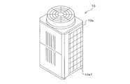
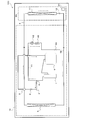
- FIG. 2 is a diagram showing an example of the shape of the casing 10a of the air-conditioning apparatus 100 according to Embodiment 1 of the present invention.
- the outdoor unit 10 has a housing 10a.
- the housing 10a is configured to have a top-blowing structure that exhausts air that has undergone heat exchange in the heat source side heat exchanger 5 from above.
- the housing 10a has, for example, a hexahedron (cuboid) shape.
- a lower portion of the housing 10a is configured by a bottom surface 10a1.
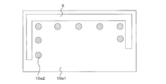
- FIG. 3 is a diagram illustrating an example of the shape of the bottom surface 10a1 of the air-conditioning apparatus 100 according to Embodiment 1 of the present invention.
- the bottom surface 10a1 is, for example, a rectangular member in plan view, and has, for example, an inclined shape.
- the heat source side heat exchanger 5 is provided on the bottom surface 10a1.
- the heat source side heat exchanger 5 has, for example, a shape along the outer periphery of the bottom surface 10a1.
- the heat source side heat exchanger 5 has, for example, a U shape.
- the bottom surface 10a1 is provided with, for example, a plurality of drain holes 10a2.
- the bottom surface 10a1 may be formed of a horizontal member that is not inclined.
- the drain hole 10a2 is an opening for discharging the drain that has been condensed in the heat source side heat exchanger 5 and has flowed down the heat source side heat exchanger 5 to the outside of the outdoor unit 10, for example, a plurality of drain holes.
- the drain hole 10a2 is provided on the bottom surface 10a1 that is inclined downward from the bottom surface 10a1 located below the heat source side heat exchanger 5 of the heat source side heat exchanger 5.
- the drain hole 10a2 is provided on the downstream side in the flow direction in which the drain flowing down the heat source side heat exchanger 5 flows through the bottom surface 10a1.
- the drain hole 10 a 2 is “a direction in which the drain flowing down the heat source side heat exchanger 5 flows through the bottom surface 10 a 1” is a direction away from the outer periphery of the bottom surface 10 a 1 than the inner surface of the heat source side heat exchanger 5.
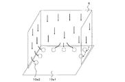
- FIG. 4 is a perspective view showing the heat source side heat exchanger 5 and the bottom surface 10a1 of the air-conditioning apparatus 100 according to Embodiment 1 of the present invention.
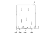
- FIG. 5 is a side view showing the heat source side heat exchanger 5 and the bottom surface 10a1 of the air-conditioning apparatus 100 according to Embodiment 1 of the present invention.
- FIGS. 4 and 5 show the direction in which drain flows when condensation occurs in the heat source side heat exchanger 5 functioning as an evaporator during heating operation and in winter, for example, below freezing.
- the arrows in FIGS. 4 and 5 indicate the flow direction of the drain.
- the drain generated in the heat source side heat exchanger 5 flows down along the heat source side heat exchanger 5 and reaches the bottom surface 10a1.
- the drain that has reached the bottom surface 10a1 is discharged to the outside of the outdoor unit 10 through the drain hole 10a2.
- FIG. 6 is a side view showing an installation example of the base heat exchanger 43 of the air-conditioning apparatus 100 according to Embodiment 1 of the present invention.
- the base heat exchanger 43 is provided so as to be inward of the center of the drain hole 10a2 in consideration of the flow of the drain, for example.
- the base heat exchanger 43 is located on the downstream side of the air flow with respect to the opening edge of the drain hole 10a2 located at the shortest distance from the heat source side heat exchanger 5.
- the base heat exchanger 43 By providing the base heat exchanger 43 in this way, the flow of the drain compared to the case where it is provided upstream of the opening edge of the drain hole 10a2 located at the shortest distance from the heat source side heat exchanger 5 is provided. This prevents the drainage performance in the drain hole 10a2 from deteriorating or the possibility that the drain freezes on the bottom surface 10a1.
- FIG. 7 is a diagram illustrating a configuration example of the refrigerant circuit in the cooling operation mode of the air-conditioning apparatus 100 according to Embodiment 1 of the present invention.
- FIG. 8 is a diagram illustrating a configuration example of the refrigerant circuit in the heating operation mode of the air-conditioning apparatus 100 according to Embodiment 1 of the present invention.
- each operation mode executed by the air conditioning apparatus 100 will be described with reference to FIGS. 7 and 8.
- the air conditioner 100 can perform the same operation in all the indoor units 20 based on instructions from the indoor units 20.
- FIG. 7 is a diagram illustrating a configuration example of the refrigerant circuit in the cooling operation mode of the air-conditioning apparatus 100 according to Embodiment 1 of the present invention.
- the flow direction of the refrigerant is indicated by arrows.
- the control means 91 switches the flow path switching device 3 to the cooling side.
- the low-temperature and low-pressure refrigerant flowing on the suction side of the compressor 1 flows into the compressor 1 and is compressed by the compressor 1.
- the refrigerant compressed by the compressor 1 becomes a high-temperature and high-pressure gas refrigerant and is discharged from the compressor 1.
- the high-temperature and high-pressure gas refrigerant discharged from the compressor 1 flows into the heat source side heat exchanger 5 through the check valve 2 and the flow path switching device 3.
- the flow rate adjusting device 42 and the opening / closing device 44 are closed. For this reason, the refrigerant discharged from the compressor 1 does not flow into the bypass circuit 41, and heat exchange is not performed in the base heat exchanger 43.
- the refrigerant that has flowed into the heat source side heat exchanger 5 becomes high-pressure liquid refrigerant while radiating heat to the outside air, and flows out of the heat source side heat exchanger 5.
- the high-pressure refrigerant that has flowed out of the heat source side heat exchanger 5 is decompressed by the expansion device 12 and becomes a low-temperature and low-pressure two-phase refrigerant.
- the low-temperature and low-pressure two-phase refrigerant flows into the use side heat exchanger 11, cools the room by absorbing heat from the room air, and flows out of the use side heat exchanger 11.
- the refrigerant that has flowed out from the use side heat exchanger 11 flows into the outdoor unit 10 again through the refrigerant pipe 4.
- the refrigerant flowing into the outdoor unit 10 passes through the flow path switching device 3 and the accumulator 6 in this order, and is sucked into the compressor 1 again.
- FIG. 8 is a diagram illustrating a configuration example of the refrigerant circuit in the heating operation mode of the air-conditioning apparatus 100 according to Embodiment 1 of the present invention.
- the flow direction of the refrigerant is indicated by arrows.
- the control means 91 switches the flow path switching device 3 to the heating side.
- the low-temperature and low-pressure refrigerant flowing on the suction side of the compressor 1 flows into the compressor 1 and is compressed by the compressor 1.
- the refrigerant compressed by the compressor 1 becomes a high-temperature and high-pressure gas refrigerant and is discharged from the compressor 1.
- a part of the high-temperature and high-pressure gas refrigerant discharged from the compressor 1 flows into the use side heat exchanger 11 through the check valve 2 and the flow path switching device 3.
- the flow rate adjusting device 42 and the opening / closing device 44 are open. For this reason, a part of the refrigerant discharged from the compressor 1 flows into the bypass circuit 41 and flows into the base heat exchanger 43.
- the refrigerant that has flowed into the use-side heat exchanger 11 becomes high-pressure liquid refrigerant while radiating heat to the room air, and flows out from the use-side heat exchanger 11.
- the high-pressure refrigerant flowing out from the use-side heat exchanger 11 is decompressed by the expansion device 12 and becomes a low-temperature and low-pressure two-phase refrigerant.
- the low-temperature and low-pressure two-phase refrigerant flows into the heat source-side heat exchanger 5 and absorbs heat from the outdoor air to become a low-temperature and low-pressure gas refrigerant and flows out of the heat source-side heat exchanger 5.
- the low-temperature and low-pressure gas refrigerant that has flowed out of the heat source side heat exchanger 5 passes through the flow path switching device 3 and the accumulator 6 in this order, and is sucked into the compressor 1 again.
- the refrigerant that did not flow toward the check valve 2 flows through the bypass circuit 41.
- the refrigerant flowing through the bypass circuit 41 passes through the flow rate adjusting device 42, the base heat exchanger 43, and the opening / closing device 44 in this order, and merges with the refrigerant flowing through the main circuit 31 at the junction 52.
- the high-temperature and high-pressure gas refrigerant flowing into the base heat exchanger 43 dissipates heat to the bottom surface 10a1 of the outdoor unit 10, and melts the ice near the drain hole 10a2.
- the bottom surface 10a1 is preferably made of a material that easily conducts heat, such as metal.
- the refrigerant condensed by radiating heat passes through the opening / closing device 44 and merges with the refrigerant flowing out of the use side heat exchanger 11.
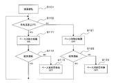
- FIG. 9 shows a control flowchart of the base heat exchanger 43 of the air-conditioning apparatus 100 according to Embodiment 1 of the present invention.
- steps S101 to S123 will be described with reference to FIG.
- step S101 the control means 91 controls various elements so as to perform the heating operation.
- the control unit 91 performs control to switch the flow path switching device 3 and the like to the heating side, and proceeds to step S102.
- step S102 the control means 91 determines whether or not the outside air temperature is 0 ° C. or less. In step S102, when it is determined that the outside air temperature is 0 ° C. or lower (YES in step S102), the control unit 91 proceeds to step S111. On the other hand, when it is determined in step S102 that the outside air temperature is higher than 0 ° C. (NO in step S102), the control unit 91 proceeds to step S121.
- step S111 the control means 91 performs control to turn on the base heat exchanger 43, and the process proceeds to step S112.
- step S112 the control means 91 returns to step S102, when it determines with heating operation being performed.
- step S112 when it is determined that the heating operation is not performed, the control unit 91 proceeds to step S113.
- step S113 the control means 91 performs control to turn off the base heat exchanger 43.
- step S121 the control means 91 performs control to turn off the base heat exchanger 43, and the process proceeds to step S122.
- step S122 the control means 91 returns to step S102, when it determines with performing the heating operation.
- step S122 when the control means 91 determines that the heating operation is not performed, the control means 91 proceeds to step S123.
- step S123 the control means 91 performs control to turn off the base heat exchanger 43.
- control to turn on the base heat exchanger 43 refers to, for example, control of the flow rate adjusting device 42 in which the control means 91 opens at least a part of the flow rate adjusting device 42.
- control to turn off the base heat exchanger 43 refers to, for example, control of the flow rate adjusting device 42 in which the control means 91 closes the flow rate adjusting device 42.
- the air-conditioning apparatus 100 is provided on the bypass circuit 41, and adjusts the amount of refrigerant flowing on the bypass circuit 41, and the heat source side heat exchanger 5.
- a base heat exchanger 43 provided on the bypass circuit 41 and on the bottom surface 10a1 of the housing 10a, and a control means 91 for controlling the opening degree of the flow rate adjusting device 42
- a drain hole 10a2 is provided in the bottom surface 10a1 of the housing 10a.
- the drainage of the drain is not impaired as compared with the conventional case. Moreover, since the circumference
- the present invention is not limited to this. That is, a means for detecting a physical quantity other than the outside air temperature may be provided, and the opening degree of the flow rate adjusting device 42 may be controlled based on the detection result.
- the base heat exchanger 43 may be turned off when the outside air humidity is a predetermined value or less, and the base heat exchanger 43 may be turned on when the outside air humidity exceeds a predetermined value.
- the opening degree of the flow rate adjusting device 42 may be controlled based on the detection results of the outside air temperature detecting means and the outside air humidity detecting means.
- the opening degree of the flow rate adjusting device 42 may be controlled so that the opening degree of the flow rate adjusting device 42 becomes larger as the detected temperature of the outside air temperature detecting means is lower. Further, the opening degree of the flow rate adjusting device 42 may be controlled so that the opening degree of the flow rate adjusting device 42 becomes larger as the detected humidity of the outside air humidity detecting means is higher.
- step S101 a reverse defrosting operation may be performed and the process may proceed to step S102.
- the control means 91 performs the cooling operation by switching the flow path switching device 3 to the cooling side.
- the high-temperature and high-pressure refrigerant discharged from the compressor 1 is guided to the heat source side heat exchanger 5 to melt the frost attached to the heat source side heat exchanger 5.
- the flow-path switching apparatus 3 is switched to the heating side, heating operation is performed, and it transfers to step S102.
Landscapes
- Engineering & Computer Science (AREA)
- Mechanical Engineering (AREA)
- General Engineering & Computer Science (AREA)
- Chemical & Material Sciences (AREA)
- Combustion & Propulsion (AREA)
- Physics & Mathematics (AREA)
- Thermal Sciences (AREA)
- Air Conditioning Control Device (AREA)
- Other Air-Conditioning Systems (AREA)
Abstract
Priority Applications (3)
| Application Number | Priority Date | Filing Date | Title |
|---|---|---|---|
| GB1622015.4A GB2542971B (en) | 2014-07-01 | 2014-07-01 | Air-conditioning apparatus |
| PCT/JP2014/067561 WO2016002009A1 (fr) | 2014-07-01 | 2014-07-01 | Climatiseur |
| JP2016530730A JP6272481B2 (ja) | 2014-07-01 | 2014-07-01 | 空気調和装置 |
Applications Claiming Priority (1)
| Application Number | Priority Date | Filing Date | Title |
|---|---|---|---|
| PCT/JP2014/067561 WO2016002009A1 (fr) | 2014-07-01 | 2014-07-01 | Climatiseur |
Publications (1)
| Publication Number | Publication Date |
|---|---|
| WO2016002009A1 true WO2016002009A1 (fr) | 2016-01-07 |
Family
ID=55018609
Family Applications (1)
| Application Number | Title | Priority Date | Filing Date |
|---|---|---|---|
| PCT/JP2014/067561 Ceased WO2016002009A1 (fr) | 2014-07-01 | 2014-07-01 | Climatiseur |
Country Status (3)
| Country | Link |
|---|---|
| JP (1) | JP6272481B2 (fr) |
| GB (1) | GB2542971B (fr) |
| WO (1) | WO2016002009A1 (fr) |
Cited By (3)
| Publication number | Priority date | Publication date | Assignee | Title |
|---|---|---|---|---|
| JP6387197B1 (ja) * | 2017-04-28 | 2018-09-05 | 日立ジョンソンコントロールズ空調株式会社 | 空気調和機 |
| JP2018189256A (ja) * | 2017-04-28 | 2018-11-29 | 日立ジョンソンコントロールズ空調株式会社 | 空気調和機 |
| JPWO2024154278A1 (fr) * | 2023-01-19 | 2024-07-25 |
Citations (7)
| Publication number | Priority date | Publication date | Assignee | Title |
|---|---|---|---|---|
| JPS6329167A (ja) * | 1986-07-21 | 1988-02-06 | 三菱重工業株式会社 | ヒ−トポンプ式空気調和機 |
| JPS63178762U (fr) * | 1987-05-12 | 1988-11-18 | ||
| JP2004218861A (ja) * | 2003-01-09 | 2004-08-05 | Denso Corp | ヒートポンプ式給湯器におけるドレンパン凍結防止構造 |
| JP2006038447A (ja) * | 2004-06-24 | 2006-02-09 | Samsung Electronics Co Ltd | 冷凍サイクル装置及びその運転方法 |
| JP2010048526A (ja) * | 2008-08-25 | 2010-03-04 | Sharp Corp | 空気調和機 |
| WO2013051177A1 (fr) * | 2011-10-03 | 2013-04-11 | 三菱電機株式会社 | Machine extérieure, et unité de climatiseur et d'alimentation en eau chaude comprenant ladite machine extérieure |
| JP2013221657A (ja) * | 2012-04-16 | 2013-10-28 | Panasonic Corp | 熱交換形換気装置 |
Family Cites Families (1)
| Publication number | Priority date | Publication date | Assignee | Title |
|---|---|---|---|---|
| JPH07120117A (ja) * | 1993-10-21 | 1995-05-12 | Kubota Corp | ヒートポンプの除霜装置 |
-
2014
- 2014-07-01 JP JP2016530730A patent/JP6272481B2/ja not_active Expired - Fee Related
- 2014-07-01 WO PCT/JP2014/067561 patent/WO2016002009A1/fr not_active Ceased
- 2014-07-01 GB GB1622015.4A patent/GB2542971B/en not_active Expired - Fee Related
Patent Citations (7)
| Publication number | Priority date | Publication date | Assignee | Title |
|---|---|---|---|---|
| JPS6329167A (ja) * | 1986-07-21 | 1988-02-06 | 三菱重工業株式会社 | ヒ−トポンプ式空気調和機 |
| JPS63178762U (fr) * | 1987-05-12 | 1988-11-18 | ||
| JP2004218861A (ja) * | 2003-01-09 | 2004-08-05 | Denso Corp | ヒートポンプ式給湯器におけるドレンパン凍結防止構造 |
| JP2006038447A (ja) * | 2004-06-24 | 2006-02-09 | Samsung Electronics Co Ltd | 冷凍サイクル装置及びその運転方法 |
| JP2010048526A (ja) * | 2008-08-25 | 2010-03-04 | Sharp Corp | 空気調和機 |
| WO2013051177A1 (fr) * | 2011-10-03 | 2013-04-11 | 三菱電機株式会社 | Machine extérieure, et unité de climatiseur et d'alimentation en eau chaude comprenant ladite machine extérieure |
| JP2013221657A (ja) * | 2012-04-16 | 2013-10-28 | Panasonic Corp | 熱交換形換気装置 |
Cited By (6)
| Publication number | Priority date | Publication date | Assignee | Title |
|---|---|---|---|---|
| JP6387197B1 (ja) * | 2017-04-28 | 2018-09-05 | 日立ジョンソンコントロールズ空調株式会社 | 空気調和機 |
| WO2018198390A1 (fr) * | 2017-04-28 | 2018-11-01 | 日立ジョンソンコントロールズ空調株式会社 | Climatiseur |
| JP2018189256A (ja) * | 2017-04-28 | 2018-11-29 | 日立ジョンソンコントロールズ空調株式会社 | 空気調和機 |
| TWI696791B (zh) * | 2017-04-28 | 2020-06-21 | 日商日立江森自控空調有限公司 | 空調機 |
| JPWO2024154278A1 (fr) * | 2023-01-19 | 2024-07-25 | ||
| WO2024154278A1 (fr) * | 2023-01-19 | 2024-07-25 | 三菱電機株式会社 | Unité extérieure de climatiseur |
Also Published As
| Publication number | Publication date |
|---|---|
| GB2542971A (en) | 2017-04-05 |
| JP6272481B2 (ja) | 2018-01-31 |
| GB201622015D0 (en) | 2017-02-08 |
| GB2542971B (en) | 2020-04-01 |
| JPWO2016002009A1 (ja) | 2017-04-27 |
Similar Documents
| Publication | Publication Date | Title |
|---|---|---|
| US9506674B2 (en) | Air conditioner including a bypass pipeline for a defrosting operation | |
| JP6381812B2 (ja) | 空気調和装置 | |
| JP6667719B2 (ja) | 空気調和機 | |
| JP2017142039A (ja) | 空気調和装置 | |
| JP6138711B2 (ja) | 空気調和装置 | |
| JP6033297B2 (ja) | 空気調和装置 | |
| CN105579794A (zh) | 空调装置 | |
| JP2017142038A (ja) | 冷凍サイクル装置 | |
| JP7183381B2 (ja) | 冷凍サイクル装置 | |
| JP4760974B2 (ja) | 冷凍装置 | |
| JP2019184207A (ja) | 空気調和装置 | |
| EP3690356A1 (fr) | Dispositif à cycle frigorifique | |
| US20210063064A1 (en) | Refrigeration device | |
| CN108779938A (zh) | 空调热水供应系统 | |
| WO2012032681A1 (fr) | Climatiseur | |
| KR102500807B1 (ko) | 공기 조화기 및 그 제어방법 | |
| CN108375145A (zh) | 一种热泵系统及其除霜控制方法 | |
| KR100821728B1 (ko) | 공기 조화 시스템 | |
| JP6272481B2 (ja) | 空気調和装置 | |
| JP2013108729A (ja) | 空気調和装置 | |
| JP5170299B1 (ja) | 空気調和装置 | |
| KR101873419B1 (ko) | 공기조화기의 냉동사이클 장치 | |
| JP7512650B2 (ja) | 空気調和機 | |
| WO2016166873A1 (fr) | Système à pompe à chaleur | |
| JP4622901B2 (ja) | 空気調和装置 |
Legal Events
| Date | Code | Title | Description |
|---|---|---|---|
| 121 | Ep: the epo has been informed by wipo that ep was designated in this application |
Ref document number: 14896659 Country of ref document: EP Kind code of ref document: A1 |
|
| ENP | Entry into the national phase |
Ref document number: 2016530730 Country of ref document: JP Kind code of ref document: A |
|
| ENP | Entry into the national phase |
Ref document number: 201622015 Country of ref document: GB Kind code of ref document: A Free format text: PCT FILING DATE = 20140701 |
|
| NENP | Non-entry into the national phase |
Ref country code: DE |
|
| 122 | Ep: pct application non-entry in european phase |
Ref document number: 14896659 Country of ref document: EP Kind code of ref document: A1 |