WO2016002116A1 - Mécanisme de point de contact et contacteur électromagnétique l'utilisant - Google Patents
Mécanisme de point de contact et contacteur électromagnétique l'utilisant Download PDFInfo
- Publication number
- WO2016002116A1 WO2016002116A1 PCT/JP2015/002054 JP2015002054W WO2016002116A1 WO 2016002116 A1 WO2016002116 A1 WO 2016002116A1 JP 2015002054 W JP2015002054 W JP 2015002054W WO 2016002116 A1 WO2016002116 A1 WO 2016002116A1
- Authority
- WO
- WIPO (PCT)
- Prior art keywords
- contact
- fixed
- movable
- pair
- arc
- Prior art date
- Legal status (The legal status is an assumption and is not a legal conclusion. Google has not performed a legal analysis and makes no representation as to the accuracy of the status listed.)
- Ceased
Links
Images




Classifications
-
- H—ELECTRICITY
- H01—ELECTRIC ELEMENTS
- H01H—ELECTRIC SWITCHES; RELAYS; SELECTORS; EMERGENCY PROTECTIVE DEVICES
- H01H50/00—Details of electromagnetic relays
- H01H50/16—Magnetic circuit arrangements
- H01H50/36—Stationary parts of magnetic circuit, e.g. yoke
- H01H50/38—Part of main magnetic circuit shaped to suppress arcing between the contacts of the relay
-
- H—ELECTRICITY
- H01—ELECTRIC ELEMENTS
- H01H—ELECTRIC SWITCHES; RELAYS; SELECTORS; EMERGENCY PROTECTIVE DEVICES
- H01H50/00—Details of electromagnetic relays
- H01H50/54—Contact arrangements
Definitions
- the present invention relates to a contact mechanism for opening and closing a current path and an electromagnetic contactor using the contact mechanism.
- the contact mechanism of Patent Document 1 includes a pair of fixed contacts arranged at a predetermined interval, a movable contact arranged so as to be able to contact with and separate from the pair of fixed contacts, and the pair of contacts. And a contact storage case formed of an insulating material that stores the stationary contact and the movable contact. Then, a pair of arc-extinguishing inner permanent magnets, which are magnetized with the same polarity on the opposing magnetic pole surfaces, are arranged close to the movable contact on the opposed inner peripheral surface along the movable contact in the contact housing case.
- the polarity is the same as that of the arc extinguishing inner permanent magnet and the coercive force is larger than that of the arc extinguishing inner permanent magnet.
- a pair of arc extinguishing outer permanent magnets are arranged.
- this contact mechanism when an arc is generated between the pair of fixed contacts and the movable contact when the movable contact is in contact with the pair of fixed contacts, the arc is generated between the pair of fixed contacts and the movable contact.
- the magnetic fluxes from the north pole to the south pole of each pair of the arc extinguishing inner permanent magnet and the arc extinguishing outer permanent magnet that are opposed to each other generate an arc between the pair of fixed and movable contacts.
- the position is traversed in the longitudinal direction of the movable contact, a Lorentz force is applied to the arc, and the arc is stretched in a direction perpendicular to the longitudinal direction of the movable contact to extinguish the arc.
- the apparatus of patent document 1 is extending the arc only with the magnetic flux generated by a permanent magnet (between the arc extinguishing inner permanent magnet and the arc extinguishing outer permanent magnet). Therefore, when interrupting a large current of several K amperes, the force for stretching the generated arc is insufficient, and the arc extinguishing direction may change to reduce the arc extinguishing performance. Accordingly, the present invention provides a contact mechanism that can generate a force that sufficiently stretches an arc to improve arc extinguishing performance even when a large current of several kiloamperes is interrupted, and an electromagnetic contactor using the contact mechanism The purpose is to provide.
- a contact mechanism includes a pair of fixed contacts having fixed contacts and a pair of movable contacts that can contact and separate from the fixed contacts of the pair of fixed contacts.
- a movable contact provided on both ends in the longitudinal direction, a contact storage case formed of an insulating material storing the pair of fixed contacts and the movable contact, and arc extinguishing fixed to the contact storage case And a permanent magnet.
- the arc current generated between the fixed contact and the movable contact and the magnetic flux of the arc extinguishing permanent magnet generate a Lorentz force in the arc, and the pair of fixed contacts
- the magnetic flux generated by the current flowing through the arc extinguishing permanent magnet matches the magnetic flux of the arc extinguishing permanent magnet.
- the electromagnetic contactor which concerns on 1 aspect of this invention WHEREIN: The said movable contact is connected with the movable iron core of the electromagnet for operation, and the said stationary contact is connected to the external connection terminal.
- the Lorentz force is generated in the arc by the arc current generated between the fixed contact and the movable contact and the magnetic flux of the arc extinguishing permanent magnet.
- the pair of fixed contacts are configured such that the magnetic flux generated by the current flowing through them matches the magnetic flux of the arc extinguishing permanent magnet, a large current is generated between the fixed contact and the movable contact.
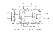
- FIG. 7 is a view taken along line VII-VII in FIG. 6.
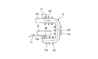
- FIG. 8 is a view taken along the line VIII-VIII in FIG. 6.
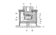
- the electromagnetic contactor 1 according to the first embodiment of the present invention shown in FIG. 1 includes a contact mechanism 2 and an electromagnet unit 20 that drives the contact mechanism 2.
- the contact mechanism 2 is housed in a contact housing case 4.
- the contact housing case 4 is made of a metal rectangular tube 5 and an insulating material such as ceramic or synthetic resin material that closes the upper end of the rectangular tube 5. And an insulating substrate 6 formed.
- the contact mechanism 2 includes a pair of fixed contacts 13 and 14 (hereinafter referred to as a first fixed contact 13 and a second fixed contact) fixed to the insulating substrate 6 via the conductor portions 11 and 12, and these The first and second fixed contacts 13a and 14a provided on the first and second fixed contacts 13 and 14 are provided with a movable contact 15 in which the first and second movable contacts 15a and 15b are opposed to each other.
- the first fixed contact 13 is equipped with a synthetic resin insulating cover 16 that restricts the occurrence of arc
- the second fixed contact 14 is also fitted with a synthetic resin insulating cover 17 that restricts the occurrence of arc.
- the movable contact 15 is supported by a connecting shaft 23 fixed to the movable plunger 22 of the electromagnet unit 20, and a through hole 24 through which the connecting shaft 23 is inserted is formed at the center of the movable contact 15.
- a flange portion 25 that protrudes outward is formed at the central portion of the connecting shaft 23 in the longitudinal direction.
- the contact spring 26 applies a predetermined urging force to the movable contact 15 by fixing the upper end of the contact spring 26 with a C ring 27 fixed to the upper end of the connecting shaft 23.
- an insulating cylinder portion 18 formed in a bottomed rectangular tube shape is disposed on the inner peripheral surface of the rectangular tube body 5 of the contact storage case 4.
- the insulating cylinder portion 18 is formed by molding an insulating synthetic resin, for example, and has an insulating function of blocking the influence of the arc on the metal square cylinder body 5.
- the electromagnet unit 20 has a U-shaped magnetic yoke 28 that is flat when viewed from the side.
- a fixed plunger 29 is disposed at the center of the bottom plate of the magnetic yoke 28, and a spool 30 is disposed outside the fixed plunger 29.
- the spool 30 includes a central cylindrical portion 31 through which the fixed plunger 29 is inserted, a lower flange portion 32 projecting radially outward from the lower end portion of the central cylindrical portion 31, and a slightly lower side than the upper end of the central cylindrical portion 31.
- the upper flange portion 33 projects outward in the radial direction.
- An exciting coil 34 is wound around a storage space formed by the central cylindrical portion 31, the lower flange portion 32, and the upper flange portion 33.
- the upper magnetic yoke 21 fixed to the upper end serving as the open end of the magnetic yoke 28 is formed with a through hole 21 a facing the central cylindrical portion 31 of the spool 30 in the central portion.
- An upper portion of the fixed plunger 29 inserted into the central cylindrical portion 31 of the spool 30 is covered with a cap 35 formed in a bottomed cylindrical shape, and is formed by extending radially outward at an open end of the cap 35.
- the flange portion 35 a is sealed and joined to the lower surface of the upper magnetic yoke 21. As a result, a sealed container is formed in which the cap 35 communicates with the upper magnetic yoke 21 through the through hole 21a.
- a movable plunger 22 having a return spring 36 disposed at the bottom is inserted into the cap 35 so as to be slidable up and down.
- the movable plunger 22 is formed with a peripheral flange portion 22 a that protrudes radially outward at an upper end portion that protrudes upward from the upper magnetic yoke 21.
- an annular driving permanent magnet 37 is fixed on the upper surface of the upper magnetic yoke 21 so as to surround the peripheral flange portion 22 a of the movable plunger 22.
- the driving permanent magnet 37 is magnetized in the vertical direction, that is, in the thickness direction so that, for example, the upper end side is an N pole and the lower end side is an S pole.
- An auxiliary yoke 39 having a through hole 38 having the same outer shape as the driving permanent magnet 37 and an inner diameter smaller than the outer diameter of the peripheral flange portion 22a of the movable plunger 22 is fixed to the upper end surface of the driving permanent magnet 37.
- the peripheral flange portion 22 a of the movable plunger 22 is in contact with the lower surface of the auxiliary yoke 39.
- a gas such as hydrogen gas, nitrogen gas, a mixed gas of hydrogen and nitrogen, air, or SF 6 is sealed in the sealed contact housing case 4.
- the movable contact 15 that constitutes the contact mechanism 2 is a conductive plate that is long in the left-right direction in FIG. 1 and made of copper, aluminum, or the like, and has a connecting shaft 23 connected to the center in the longitudinal direction.
- a first movable contact 15a and a second movable contact 15b are formed on the lower surfaces at both ends in the direction.
- the first fixed contact 13 and the second fixed contact 14 constituting the contact mechanism 2 are C-shaped conductive plates made of copper, aluminum, or the like, and are movable contacts.
- the elements 15 are spaced apart from each other in the longitudinal direction, and are fixed to the insulating substrate 6 via the conductor portions 11 and 12.
- the first fixed contact 13 is disposed on the first movable contact 15a side of the movable contact 15 in a direction orthogonal to the longitudinal direction, and faces the first movable contact 15a of the movable contact 15 from below.
- the first conductive plate portion 13b provided with the first fixed contact 13a on the upper surface, and the second conductive member bent from the end of the first conductive plate portion 13b away from the movable contact 15 and extending upward.
- a plate portion 13c and a third conductive plate portion 13d that is bent from the upper end of the second conductive plate portion 13c and extends above the movable contact 15 are provided.
- the second fixed contact 14 is disposed perpendicular to the longitudinal direction on the second movable contact 15 b side of the movable contact 15 and parallel to the first fixed contact 13. 2 is opposed to the movable contact 15b from the lower side and is bent from the end of the first conductive plate 14b provided with the second fixed contact 14a on the upper surface and the first conductive plate 14b away from the movable contact 15 And a third conductive plate portion 14d that is bent from the upper end of the second conductive plate portion 14c and extends above the movable contact 15. .
- the movable contact 15 is in a released state, and the movable contacts 15a, 15a located on both ends in the longitudinal direction and the fixed contacts 13a, 14a of the fixed contacts 13, 14 are spaced apart from each other with a predetermined interval. It becomes. Further, the movable contact 15 is set so that the movable contacts 15 a and 15 b are in contact with the fixed contacts 13 a and 14 a of the fixed contacts 13 and 14 with a predetermined contact pressure by the contact spring 26 at the closing position. .
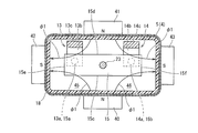
- first to fourth arc extinguishing permanent magnets 40 to 43 are arranged on the outer periphery of the rectangular tube 5.
- the first arc extinguishing permanent magnet 40 is fixed to the outer peripheral surface of the rectangular tube 5 facing the one side surface 15c in the width direction of the movable contact 15, and the second arc extinguishing permanent magnet 41 is
- the movable contact 15 is fixed to the outer peripheral surface of the rectangular tube 5 facing the other side surface 15d in the width direction.
- the first and second arc extinguishing side permanent magnets 41 and 42 are magnetized so that the magnetic pole surfaces in contact with the rectangular tube 5 in the thickness direction are N poles.
- the third arc extinguishing permanent magnet 42 is fixed to the outer peripheral surface of the rectangular tube 5 facing one side surface 15e in the longitudinal direction of the movable contact 15, and the fourth arc extinguishing permanent magnet 43. Is fixed to the outer peripheral surface of the rectangular tube 5 facing the other side surface 15f in the longitudinal direction of the movable contact 15.
- the third and fourth arc extinguishing side permanent magnets 42 and 43 are magnetized so that the magnetic pole surface in contact with the rectangular tube 5 in the thickness direction becomes the S pole.
- the first to fourth arc extinguishing permanent magnets 40 to 44 are fixed to the outer peripheral surface of the rectangular tube body 5 constituting the contact housing case 4.
- the magnetic flux ⁇ 1 flowing through the first fixed contact 13 passes through the vicinity of the opposed portion of the first fixed contact 13a of the first fixed contact 13 and the first movable contact 15a of the movable contact 15, and increases in magnetic flux density toward the left side in the left-right direction. Cross at.
- the magnetic flux ⁇ 1 flowing through the S pole of the fourth arc extinguishing permanent magnet 43 passes near a portion where the second fixed contact 14a of the second fixed contact 14 and the second movable contact 15b of the movable contact 15 are opposed to each other. Crossing with a large magnetic flux density toward the right side in the horizontal direction.
- the pair of fixed contacts 13, 14 arranged in the contact housing case 4 are arranged on both ends in the longitudinal direction of the movable contact 15 and on the other side surface 15 d side in the width direction.
- the arc extinguishing space 45 is disposed on one side 15c side in the width direction of the movable contact 15 opposite to the pair of fixed contacts 13 and 14, and extends in a direction orthogonal to the direction. 46 is formed.
- the insulating case of the present invention corresponds to the insulating covers 16 and 17 and the insulating cylindrical portion 18, and the fixed contact of the present invention corresponds to the first fixed contact 13a and the second fixed contact 14a, and the pair of movable members of the present invention.
- the contact corresponds to the first movable contact 15a and the second movable contact 15b
- the arc extinguishing permanent magnet of the present invention corresponds to the first to fourth arc extinguishing permanent magnets 40 to 43, and the movable iron core of the present invention.
- the electromagnet for operation of the present invention corresponds to the electromagnet unit 20.
- the attractive force generated by the magnetic force of the driving permanent magnet 37 acts on the auxiliary yoke 39, and the peripheral flange portion 22a of the movable plunger 22 is attracted. For this reason, the upper surface of the peripheral flange portion 22 a of the movable plunger 22 is in contact with the lower surface of the auxiliary yoke 39.
- the first movable contact 15 a and the second movable contact 15 b of the movable contact 15 of the contact mechanism 2 connected to the movable plunger 22 via the connecting shaft 23 are the first fixed contact of the first fixed contact 13. 13a is spaced apart from the second fixed contact 14a of the second fixed contact 14 upward by a predetermined distance. For this reason, the current path between the first fixed contact 13 and the second fixed contact 14 is in a cut-off state, and the contact mechanism 2 is in an open state.
- the exciting coil 34 of the electromagnet unit 20 is energized from this released state, an exciting force is generated in the electromagnet unit 20, and the movable plunger 22 is resisted against the urging force of the return spring 36 and the attracting force of the driving permanent magnet 37. Press down.
- the lowering of the movable plunger 22 stops when the lower surface of the peripheral flange portion 22 a hits the upper surface of the upper magnetic yoke 21.
- the movable contact 15 connected to the movable plunger 22 via the connecting shaft 23 is also lowered, and the first movable contact 15a of the movable contact 15 of the contact mechanism 2 is lowered.
- the second movable contact 15 b comes into contact with the first fixed contact 13 a of the first fixed contact 13 and the second fixed contact 14 a of the second fixed contact 14 with the contact pressure of the contact spring 26. For this reason, a large current from the power supply source is brought into a closed state in which it is supplied to the load device through the first fixed contact 13, the movable contact 15 and the second fixed contact 14.
- the first movable contact 15 a and the second movable contact 15 b of the movable contact 15 are connected to the first fixed contact 13 a and the second fixed contact 13 of the first fixed contact 13.
- the contact 14 is in contact with the second fixed contact 14a.
- a first arc 50 is generated between the first movable contact 15a of the movable contact 15 and the first fixed contact 13a of the first fixed contact 13 as shown in FIG.
- a second arc 51 is generated between the second movable contact 15 b of the movable contact 15 and the second fixed contact 14 a of the second fixed contact 14, and the current conduction state is continued by these arcs 50, 51.
- the current direction of the first arc 50 is a direction from the first fixed contact 13a to the first movable contact 15a
- the current direction of the second arc 51 is from the second movable contact 15b to the second fixed contact 14a. It is the direction to go.
- the magnetic flux ⁇ 1 flowing out from the N pole of the magnet 41 and flowing to the S pole of the third arc extinguishing permanent magnet 42 passes near the first arc 50 and is on one side surface 15e in the longitudinal direction of the movable contact 15. Occurs outward.
- a magnetic flux ⁇ 1 flowing through the S pole of the fourth arc extinguishing permanent magnet 43 is generated toward the outside of the other side surface 15f in the longitudinal direction of the movable contact 15 through the vicinity of the second arc 51.
- the first fixed contact 13 is arranged in the order of the conductor portion 11 to the third conductive plate portion 13 d, the second conductive plate portion 13 c, and the first conductive plate portion 13 b.
- Current flows, and a magnetic flux ⁇ 2 due to the current is generated around each third conductive plate portion 13d, second conductive plate portion 13c, and first conductive plate portion 13b.
- a current flows through the second fixed contact 14 in the order of the first conductive plate portion 14b, the second conductive plate portion 14c, and the third conductive plate portion 13d.
- Magnetic flux ⁇ 2 due to current is generated around the portion 14b, the second conductive plate portion 14c, and the third conductive plate portion 13d.
- the first fixed contact 13a of the first fixed contact 13 and the first movable contact 15a of the movable contact 15a of the movable contact 15 As shown in FIG. 7, the first fixed contact 13a side to the first movable contact 15a side One arc 50 flows, and a magnetic flux ⁇ 1 generated by the first arc extinguishing permanent magnet 40, the second arc extinguishing permanent magnet 41, and the third arc extinguishing permanent magnet 42 is one of the longitudinal directions of the movable contact 15.
- the magnetic flux ⁇ 2 is generated by the current that flows toward the outside of the side surface 15e and flows through the first fixed contact 13.
- the second arc 51 flows through the first arc extinguishing permanent magnet 40, the second arc extinguishing permanent magnet 41, and the fourth arc extinguishing permanent magnet 43 so that the magnetic flux ⁇ 1 is generated in the longitudinal direction of the movable contact 15. Is generated toward the outside of the other side surface 15f, and a magnetic flux ⁇ 2 is generated by the current flowing through the second fixed contact 14.
- the direction in which the current of the first arc 50 flows and the direction of the current flowing in the second conductive plate portion 13 c of the first fixed contact 13 are reversed. Due to this, the electromagnetic repulsive force works and the first arc 50 is stretched toward the arc extinguishing space 45. Furthermore, as shown in FIG. 8, the direction of the current flowing through the second arc 51 and the direction of the current flowing through the second conductive plate portion 14c of the second fixed contact 14 are reversed, and the currents in the opposite directions are reversed. Due to this, the electromagnetic repulsive force works, and the second arc 51 is stretched toward the arc extinguishing space 46.
- the first arc 50 can be reliably extinguished.
- a large current of several K amperes flows between the second fixed contact 14a and the second movable contact 15b, the first arc extinguishing permanent magnet 40, the second arc extinguishing permanent magnet 41, and the second The magnetic flux ⁇ 1 generated by the four-arc extinguishing permanent magnet 43, the magnetic flux ⁇ 2 generated by the current flowing through the second fixed contact 14, and the second generated between the second fixed contact 14a and the second movable contact 15b.
- the direction in which the current of the first arc 50 flows and the direction of the current flowing in the second conductive plate portion 13c of the first fixed contact 13 are reversed, and the action of the electromagnetic repulsive force due to the reverse direction of these currents. Since the first arc 50 is further extended toward the arc extinguishing space 45, the arc extinguishing of the first arc 50 can be promoted. Similarly, the direction in which the current of the second arc 51 flows and the direction of the current flowing in the second conductive plate portion 14c of the second stationary contact 14 are reversed, and the action of electromagnetic repulsive force due to the reverse direction of these currents. Since the second arc 51 is further stretched toward the arc extinguishing space 46, the arc extinguishing of the second arc 51 can be promoted.
- the first fixed contact 13 (and the second fixed contact 14) constituting the contact mechanism 2 is formed of a C-shaped conductive plate in a side view.
- the first movable contact 15a (and the second movable contact 15b side) of the movable contact 15 and the first movable contact 15a (and the second movable contact 15b) from the lower side are not limited thereto.
- the first conductive plate portion provided with the first fixed contact (and the second fixed contact) on the upper surface and the first conductive plate portion remote from the movable contact 15 are bent and extended upward. It may be a conductive plate having an L shape in a side view and formed of a second conductive plate portion.
- the first to fourth arc extinguishing permanent magnets 40 to 43 are fixed to the outer peripheral surface of the rectangular cylinder 5 constituting the contact housing case 4, but the present invention is not limited to this. Instead, it forms a magnetic flux that passes near the opposed portion of the first fixed contact 13a of the first fixed contact 13 and the first movable contact 15a of the movable contact 15 toward the left in the left-right direction, and the second Any other shape can be used as long as it forms a magnetic flux that passes near the opposing portion of the second fixed contact 14a of the fixed contact 14 and the second movable contact 15b of the movable contact 15 and moves to the right in the left-right direction.
- the permanent magnet may be arranged.
- the contact mechanism according to the present invention and the electromagnetic contactor using the contact mechanism generate a force that sufficiently stretches the arc even when a large current of several kiloamperes is interrupted, and have the arc extinguishing performance. Useful to improve.
- Electromagnetic contactor 2 ... Contact mechanism, 4 ... Contact storage case, 5 ... Square cylinder body, 6 ... Insulating substrate, 7 ... Flange part, 9,10 ... Through-hole, 11, 12 ... Conductor part, 13th 1 fixed contact, 13a ... 1st fixed contact, 13b ... 1st conductive plate part, 13c ... 2nd conductive plate part, 13d ... 3rd conductive plate part, 14 ... 2nd fixed contact, 14a ... 2nd fixed contact , 14b ... 1st conductive plate part, 14c ... 2nd conductive plate part, 14d ... 3rd conductive plate part, 15 ... movable contact, 15a ...
Landscapes
- Physics & Mathematics (AREA)
- Electromagnetism (AREA)
- Electromagnets (AREA)
- Arc-Extinguishing Devices That Are Switches (AREA)
Abstract
La présente invention concerne un mécanisme de point de contact qui comprend : une paire de pièces de contact (13, 14) fixes, chacune ayant un point de contact (13a, 14a) fixe ; une pièce de contact (15) mobile pourvue d'une paire de points de contact (15a, 15b) mobiles au niveau de deux côtés d'extrémité dans le sens de sa longueur, ladite paire de points de contact mobiles étant capable d'établir un contact avec les points de contact (13a, 14a) fixes de la paire de pièces de contact fixes et de s'en séparer ; un boîtier (16, 17, 18) formé à partir d'un matériau isolant et logeant la paire de pièces de contact fixes et la pièce de contact mobile ; et des aimants permanents à extinction d'arc (40 à 43) fixés au boîtier (16, 17, 18). Les courants provenant des arcs (50, 51), qui se produisent entre les points de contact fixes et les points de contact mobiles et le flux magnétique provenant des aimants permanents à extinction d'arc (40 à 43) provoquent la génération de forces de Lorentz (F1, F2) par les arcs (50, 51), tandis que la paire de pièces de contact (13, 14) fixes est telle que les flux magnétiques produits par le courant s'écoulant en son sein correspondent aux flux magnétiques des aimants permanents à extinction d'arc (40 à 43).
Applications Claiming Priority (2)
| Application Number | Priority Date | Filing Date | Title |
|---|---|---|---|
| JP2014134332A JP6359896B2 (ja) | 2014-06-30 | 2014-06-30 | 接点機構及びこれを使用した電磁接触器 |
| JP2014-134332 | 2014-06-30 |
Publications (1)
| Publication Number | Publication Date |
|---|---|
| WO2016002116A1 true WO2016002116A1 (fr) | 2016-01-07 |
Family
ID=55018700
Family Applications (1)
| Application Number | Title | Priority Date | Filing Date |
|---|---|---|---|
| PCT/JP2015/002054 Ceased WO2016002116A1 (fr) | 2014-06-30 | 2015-04-13 | Mécanisme de point de contact et contacteur électromagnétique l'utilisant |
Country Status (2)
| Country | Link |
|---|---|
| JP (1) | JP6359896B2 (fr) |
| WO (1) | WO2016002116A1 (fr) |
Cited By (10)
| Publication number | Priority date | Publication date | Assignee | Title |
|---|---|---|---|---|
| CN105719911A (zh) * | 2016-04-29 | 2016-06-29 | 浙江英洛华新能源科技有限公司 | 高压直流继电器挡弧结构 |
| CN106710968A (zh) * | 2016-12-20 | 2017-05-24 | 北京双杰电气股份有限公司 | 一种直流接触器 |
| CN106783411A (zh) * | 2016-12-20 | 2017-05-31 | 北京双杰电气股份有限公司 | 一种直流接触器 |
| WO2017185525A1 (fr) * | 2016-04-29 | 2017-11-02 | 浙江英洛华新能源科技有限公司 | Dispositif d'isolation d'arc opposé de relais à courant continu haute tension |
| CN112470243A (zh) * | 2018-08-10 | 2021-03-09 | 欧姆龙株式会社 | 继电器 |
| CN113168999A (zh) * | 2018-12-28 | 2021-07-23 | 欧姆龙株式会社 | 电磁继电器 |
| CN113168997A (zh) * | 2018-12-28 | 2021-07-23 | 欧姆龙株式会社 | 电磁继电器 |
| CN114342033A (zh) * | 2019-08-28 | 2022-04-12 | Ls电气株式会社 | 电弧路径形成部及包括其的直流继电器 |
| KR20230072419A (ko) * | 2021-11-17 | 2023-05-24 | 샤먼 홍파 일렉트릭 파워 컨트롤즈 컴퍼니 리미티드 | 절연 능력을 향상할 수 있는 고압 직류 릴레이 |
| EP4148760A4 (fr) * | 2020-05-06 | 2024-06-05 | LS Electric Co., Ltd. | Unité de formation de trajet d'arc et relais à courant continu la comprenant |
Families Citing this family (4)
| Publication number | Priority date | Publication date | Assignee | Title |
|---|---|---|---|---|
| JP6907801B2 (ja) * | 2017-08-10 | 2021-07-21 | オムロン株式会社 | 電磁継電器 |
| JP7135567B2 (ja) | 2018-08-10 | 2022-09-13 | オムロン株式会社 | リレー |
| JP7056549B2 (ja) * | 2018-12-28 | 2022-04-19 | オムロン株式会社 | 電磁継電器 |
| KR102795563B1 (ko) | 2019-06-18 | 2025-04-15 | 엘에스일렉트릭(주) | 직류 릴레이 |
Citations (2)
| Publication number | Priority date | Publication date | Assignee | Title |
|---|---|---|---|---|
| JPS6072626U (ja) * | 1983-10-25 | 1985-05-22 | オリンパス光学工業株式会社 | カメラの携帯保持具 |
| JP2001118450A (ja) * | 1999-10-14 | 2001-04-27 | Matsushita Electric Works Ltd | 接点装置 |
Family Cites Families (1)
| Publication number | Priority date | Publication date | Assignee | Title |
|---|---|---|---|---|
| JPS60186648U (ja) * | 1984-05-18 | 1985-12-11 | 富士電機株式会社 | 電磁接触器 |
-
2014
- 2014-06-30 JP JP2014134332A patent/JP6359896B2/ja not_active Expired - Fee Related
-
2015
- 2015-04-13 WO PCT/JP2015/002054 patent/WO2016002116A1/fr not_active Ceased
Patent Citations (2)
| Publication number | Priority date | Publication date | Assignee | Title |
|---|---|---|---|---|
| JPS6072626U (ja) * | 1983-10-25 | 1985-05-22 | オリンパス光学工業株式会社 | カメラの携帯保持具 |
| JP2001118450A (ja) * | 1999-10-14 | 2001-04-27 | Matsushita Electric Works Ltd | 接点装置 |
Cited By (19)
| Publication number | Priority date | Publication date | Assignee | Title |
|---|---|---|---|---|
| CN105719911A (zh) * | 2016-04-29 | 2016-06-29 | 浙江英洛华新能源科技有限公司 | 高压直流继电器挡弧结构 |
| WO2017185525A1 (fr) * | 2016-04-29 | 2017-11-02 | 浙江英洛华新能源科技有限公司 | Dispositif d'isolation d'arc opposé de relais à courant continu haute tension |
| US10453628B2 (en) | 2016-04-29 | 2019-10-22 | Zhejiang Innuovo New Energy Technology Co., Ltd. | Opposite arc isolation device of high voltage direct current relay |
| CN106710968A (zh) * | 2016-12-20 | 2017-05-24 | 北京双杰电气股份有限公司 | 一种直流接触器 |
| CN106783411A (zh) * | 2016-12-20 | 2017-05-31 | 北京双杰电气股份有限公司 | 一种直流接触器 |
| CN106710968B (zh) * | 2016-12-20 | 2020-08-04 | 北京双杰电气股份有限公司 | 一种直流接触器 |
| CN106783411B (zh) * | 2016-12-20 | 2020-08-04 | 北京双杰电气股份有限公司 | 一种直流接触器 |
| CN112470243A (zh) * | 2018-08-10 | 2021-03-09 | 欧姆龙株式会社 | 继电器 |
| CN113168999A (zh) * | 2018-12-28 | 2021-07-23 | 欧姆龙株式会社 | 电磁继电器 |
| CN113168997A (zh) * | 2018-12-28 | 2021-07-23 | 欧姆龙株式会社 | 电磁继电器 |
| CN114342033A (zh) * | 2019-08-28 | 2022-04-12 | Ls电气株式会社 | 电弧路径形成部及包括其的直流继电器 |
| US12062509B2 (en) | 2019-08-28 | 2024-08-13 | Ls Electric Co., Ltd. | ARC path forming unit and direct current relay including same |
| EP4148760A4 (fr) * | 2020-05-06 | 2024-06-05 | LS Electric Co., Ltd. | Unité de formation de trajet d'arc et relais à courant continu la comprenant |
| KR20230072419A (ko) * | 2021-11-17 | 2023-05-24 | 샤먼 홍파 일렉트릭 파워 컨트롤즈 컴퍼니 리미티드 | 절연 능력을 향상할 수 있는 고압 직류 릴레이 |
| EP4184544A1 (fr) * | 2021-11-17 | 2023-05-24 | Xiamen Hongfa Electric Power Controls Co., Ltd. | Relais à courant continu haute tension capable d'améliorer la capacité d'isolation |
| JP2023074501A (ja) * | 2021-11-17 | 2023-05-29 | シァメン ホンファ エレクトリック パワー コントロールズ カンパニー リミテッド | 絶縁能力を向上することができる高電圧直流リレー |
| JP7482975B2 (ja) | 2021-11-17 | 2024-05-14 | シァメン ホンファ エレクトリック パワー コントロールズ カンパニー リミテッド | 絶縁能力を向上することができる高電圧直流リレー |
| US12183534B2 (en) * | 2021-11-17 | 2024-12-31 | Xiamen Hongfa Electric Power Controls Co., Ltd. | High-voltage direct current relay capable of improving insulation capability |
| KR102772527B1 (ko) * | 2021-11-17 | 2025-02-26 | 샤먼 홍파 일렉트릭 파워 컨트롤즈 컴퍼니 리미티드 | 절연 능력을 향상할 수 있는 고압 직류 릴레이 |
Also Published As
| Publication number | Publication date |
|---|---|
| JP2016012504A (ja) | 2016-01-21 |
| JP6359896B2 (ja) | 2018-07-18 |
Similar Documents
| Publication | Publication Date | Title |
|---|---|---|
| JP6359896B2 (ja) | 接点機構及びこれを使用した電磁接触器 | |
| JP6375745B2 (ja) | 接点機構及びこれを使用した電磁接触器 | |
| JP6081787B2 (ja) | 接点装置及びこれを使用した電磁開閉器 | |
| JP5856426B2 (ja) | 接点装置及びこれを使用した電磁接触器 | |
| JP5307779B2 (ja) | 電磁開閉器 | |
| CN103155083B (zh) | 接触装置和使用接触装置的电磁开关 | |
| JP6455171B2 (ja) | 電磁接触器 | |
| CN102804315B (zh) | 接触装置和使用接触装置的电磁开关 | |
| JP5806562B2 (ja) | 電磁接触器 | |
| JP5986419B2 (ja) | 接点装置及びこれを使用した電磁開閉器 | |
| JP5918424B2 (ja) | 電磁接触器 | |
| JP2016012505A (ja) | 接点機構及びこれを使用した電磁接触器 | |
| JP7077890B2 (ja) | 接点機構及びこれを使用した電磁接触器 | |
| JP5990090B2 (ja) | 電磁開閉器 | |
| WO2012157215A1 (fr) | Mécanisme de contact et contacteur électromagnétique l'utilisant | |
| WO2012157172A1 (fr) | Contacteur électromagnétique | |
| JP2013098051A (ja) | 電磁接触器 | |
| JP2013246873A (ja) | 接点装置 | |
| JP2020031037A (ja) | リレー | |
| JP6291871B2 (ja) | 接点装置及びこれを使用した電磁接触器 | |
| JPWO2019103063A1 (ja) | 接点モジュール、接点装置、電磁継電器モジュール、及び電気機器 | |
| JP2021093277A (ja) | 電磁接触器 | |
| JP2021118111A (ja) | 電磁接触器 | |
| JP7255440B2 (ja) | 接点機構及びこれを使用した電磁接触器 | |
| JP7259611B2 (ja) | 接点機構及びこれを使用した電磁接触器 |
Legal Events
| Date | Code | Title | Description |
|---|---|---|---|
| 121 | Ep: the epo has been informed by wipo that ep was designated in this application |
Ref document number: 15814938 Country of ref document: EP Kind code of ref document: A1 |
|
| NENP | Non-entry into the national phase |
Ref country code: DE |
|
| 122 | Ep: pct application non-entry in european phase |
Ref document number: 15814938 Country of ref document: EP Kind code of ref document: A1 |