WO2016002236A1 - 構造物の屋内監視システム及び方法 - Google Patents
構造物の屋内監視システム及び方法 Download PDFInfo
- Publication number
- WO2016002236A1 WO2016002236A1 PCT/JP2015/051360 JP2015051360W WO2016002236A1 WO 2016002236 A1 WO2016002236 A1 WO 2016002236A1 JP 2015051360 W JP2015051360 W JP 2015051360W WO 2016002236 A1 WO2016002236 A1 WO 2016002236A1
- Authority
- WO
- WIPO (PCT)
- Prior art keywords
- distance
- unit
- position information
- unmanned floating
- floating machine
- Prior art date
- Legal status (The legal status is an assumption and is not a legal conclusion. Google has not performed a legal analysis and makes no representation as to the accuracy of the status listed.)
- Ceased
Links
Images


Classifications
-
- G—PHYSICS
- G05—CONTROLLING; REGULATING
- G05D—SYSTEMS FOR CONTROLLING OR REGULATING NON-ELECTRIC VARIABLES
- G05D1/00—Control of position, course, altitude or attitude of land, water, air or space vehicles, e.g. using automatic pilots
- G05D1/0011—Control of position, course, altitude or attitude of land, water, air or space vehicles, e.g. using automatic pilots associated with a remote control arrangement
- G05D1/0038—Control of position, course, altitude or attitude of land, water, air or space vehicles, e.g. using automatic pilots associated with a remote control arrangement by providing the operator with simple or augmented images from one or more cameras located onboard the vehicle, e.g. tele-operation
-
- G—PHYSICS
- G01—MEASURING; TESTING
- G01B—MEASURING LENGTH, THICKNESS OR SIMILAR LINEAR DIMENSIONS; MEASURING ANGLES; MEASURING AREAS; MEASURING IRREGULARITIES OF SURFACES OR CONTOURS
- G01B21/00—Measuring arrangements or details thereof, where the measuring technique is not covered by the other groups of this subclass, unspecified or not relevant
-
- G—PHYSICS
- G01—MEASURING; TESTING
- G01C—MEASURING DISTANCES, LEVELS OR BEARINGS; SURVEYING; NAVIGATION; GYROSCOPIC INSTRUMENTS; PHOTOGRAMMETRY OR VIDEOGRAMMETRY
- G01C15/00—Surveying instruments or accessories not provided for in groups G01C1/00 - G01C13/00
-
- G—PHYSICS
- G01—MEASURING; TESTING
- G01C—MEASURING DISTANCES, LEVELS OR BEARINGS; SURVEYING; NAVIGATION; GYROSCOPIC INSTRUMENTS; PHOTOGRAMMETRY OR VIDEOGRAMMETRY
- G01C21/00—Navigation; Navigational instruments not provided for in groups G01C1/00 - G01C19/00
- G01C21/20—Instruments for performing navigational calculations
- G01C21/206—Instruments for performing navigational calculations specially adapted for indoor navigation
-
- G—PHYSICS
- G01—MEASURING; TESTING
- G01C—MEASURING DISTANCES, LEVELS OR BEARINGS; SURVEYING; NAVIGATION; GYROSCOPIC INSTRUMENTS; PHOTOGRAMMETRY OR VIDEOGRAMMETRY
- G01C23/00—Combined instruments indicating more than one navigational value, e.g. for aircraft; Combined measuring devices for measuring two or more variables of movement, e.g. distance, speed or acceleration
-
- G—PHYSICS
- G01—MEASURING; TESTING
- G01C—MEASURING DISTANCES, LEVELS OR BEARINGS; SURVEYING; NAVIGATION; GYROSCOPIC INSTRUMENTS; PHOTOGRAMMETRY OR VIDEOGRAMMETRY
- G01C3/00—Measuring distances in line of sight; Optical rangefinders
- G01C3/02—Details
- G01C3/06—Use of electric means to obtain final indication
- G01C3/08—Use of electric radiation detectors
-
- G—PHYSICS
- G01—MEASURING; TESTING
- G01N—INVESTIGATING OR ANALYSING MATERIALS BY DETERMINING THEIR CHEMICAL OR PHYSICAL PROPERTIES
- G01N21/00—Investigating or analysing materials by the use of optical means, i.e. using sub-millimetre waves, infrared, visible or ultraviolet light
- G01N21/84—Systems specially adapted for particular applications
-
- G—PHYSICS
- G05—CONTROLLING; REGULATING
- G05D—SYSTEMS FOR CONTROLLING OR REGULATING NON-ELECTRIC VARIABLES
- G05D1/00—Control of position, course, altitude or attitude of land, water, air or space vehicles, e.g. using automatic pilots
- G05D1/0094—Control of position, course, altitude or attitude of land, water, air or space vehicles, e.g. using automatic pilots involving pointing a payload, e.g. camera, weapon, sensor, towards a fixed or moving target
-
- B—PERFORMING OPERATIONS; TRANSPORTING
- B64—AIRCRAFT; AVIATION; COSMONAUTICS
- B64U—UNMANNED AERIAL VEHICLES [UAV]; EQUIPMENT THEREFOR
- B64U10/00—Type of UAV
- B64U10/10—Rotorcrafts
- B64U10/13—Flying platforms
- B64U10/14—Flying platforms with four distinct rotor axes, e.g. quadcopters
-
- B—PERFORMING OPERATIONS; TRANSPORTING
- B64—AIRCRAFT; AVIATION; COSMONAUTICS
- B64U—UNMANNED AERIAL VEHICLES [UAV]; EQUIPMENT THEREFOR
- B64U2101/00—UAVs specially adapted for particular uses or applications
- B64U2101/30—UAVs specially adapted for particular uses or applications for imaging, photography or videography
-
- B—PERFORMING OPERATIONS; TRANSPORTING
- B64—AIRCRAFT; AVIATION; COSMONAUTICS
- B64U—UNMANNED AERIAL VEHICLES [UAV]; EQUIPMENT THEREFOR
- B64U2101/00—UAVs specially adapted for particular uses or applications
- B64U2101/70—UAVs specially adapted for particular uses or applications for use inside enclosed spaces, e.g. in buildings or in vehicles
-
- B—PERFORMING OPERATIONS; TRANSPORTING
- B64—AIRCRAFT; AVIATION; COSMONAUTICS
- B64U—UNMANNED AERIAL VEHICLES [UAV]; EQUIPMENT THEREFOR
- B64U2201/00—UAVs characterised by their flight controls
- B64U2201/20—Remote controls
Definitions
- the present invention relates to an indoor monitoring system and method for a structure.
- boiler furnaces used in thermal power plants need to be opened at the time of production and periodically after the start of operation, and an operator needs to enter the inside for maintenance inspection.
- this maintenance inspection it is necessary to clarify the inspection location, but the boiler furnace has a large capacity and it is difficult to accurately grasp the inspection location visually. Therefore, conventionally, the worker's whereabouts or maintenance inspection position has been grasped by measuring and marking the height position and the left and right position of the inspection location with a tape measure or the like. Requires a lot of labor, cost, and inspection period.
- Patent Document 1 a technique for cleaning the inside of a structure such as a chimney with an unmanned inspection device.
- Patent Document 1 a technique for cleaning the inside of a structure such as a chimney with an unmanned inspection device.
- this proposal also requires a frame for installing the wire, and labor, cost, and inspection period are required for the preparation.
- Patent Document 2 For outdoor structures, it has been proposed to apply unmanned inspection technology that does not require scaffolding using a drone and GPS (Global Positioning System) (Patent Document 2).
- Patent Document 3 a system capable of indoor flight without using GPS has also been proposed.
- Patent Document 3 has a problem that a feature point (or pattern) is required on the ground instead of using GPS, and the place where the feature point (or pattern) can be installed is limited. Moreover, since structures such as boiler furnaces and chimneys are closed spaces in the dark, there is a problem that feature points cannot be confirmed.
- the present invention enables an uninhabited inspection in which internal position information is ensured, for example, an indoor monitoring system for a structure that can reduce labor, cost, and inspection period due to the absence of scaffolding construction, and It is an object to provide a method.
- the first invention of the present invention for solving the above-described problems is an unmanned floating machine equipped with a floating means for floating the inside of a structure by remote operation, and the unmanned floating machine mounted on the unmanned floating machine.
- a distance measuring unit that measures the distance between the machine and the inner wall surface of the structure, and an inertial measurement unit that is mounted on the unmanned floating machine, grasps a body posture of the unmanned floating machine, and is mounted on the unmanned floating machine, The current position of the unmanned floating machine according to the imaging unit for imaging the structure on the wall surface side of the structure, the operation unit for remotely operating the unmanned floating machine, the information of the distance measuring unit, and the information of the inertial measuring unit
- a flight position information acquisition unit that acquires information, a monitor unit that displays image information from the imaging unit, and position information from the flight position information acquisition unit, and in the flight position information acquisition unit,
- the unmanned floating by the distance measurement unit Obtained by the horizontal distance measurement step of measuring horizontal distance information between the inner wall surface of the structure and the posture angle
- An indoor monitoring system for a structure is characterized in that a distance acquisition step and a horizontal current position information acquisition step of acquiring horizontal current position information from known cross-sectional shape information of the structure are executed.
- the distance measurement unit measures distance information in the height direction of either the top or bottom of the unmanned floating aircraft and the structure.
- a distance measurement step a posture angle acquisition step for acquiring the posture angle of the unmanned floating machine, and a height for correcting the distance information in the height direction using the posture angle acquired in the posture angle acquisition step.
- An indoor monitoring of a structure comprising: performing a vertical distance correction step, and a height direction current position information acquisition step of acquiring current position information in a height direction from known vertical cross-sectional shape information of the structure In the system.
- a third invention is an indoor monitoring system for a structure according to the first invention, wherein a plurality of measurements are performed in the horizontal distance measurement step, and an average distance is used as the horizontal distance information.
- a fourth invention is the indoor monitoring system for a structure according to the second invention, wherein a plurality of measurements in the height direction distance measurement step are performed, and the averaged distance is used as distance information in the height direction. It is in.
- a fifth invention is the first or second invention, wherein the flight position information acquisition unit is mounted on an unmanned floating aircraft, the acquired current position information is transmitted to the ground side by the transmission unit, and is displayed on the monitor unit. It is in the indoor monitoring system of the structure characterized by.
- the flight position information acquisition unit is mounted on a controller terminal on the ground unit side, and the information on the distance measurement unit and the information on the inertia measurement unit are transmitted by the transmission unit to the ground unit.
- the current position information is displayed on the monitor unit after being transmitted to the side and processed in the flight position information acquisition unit.
- a seventh invention is an indoor surveillance system for a structure according to the first or second invention, wherein the imaging unit is one or both of a still image capturing unit and a moving image capturing unit.
- An eighth invention is an indoor surveillance system for a structure according to the first or second invention, wherein a guard portion is provided around the unmanned floating machine.
- the 9th invention uses the unmanned floating machine provided with the floating means which floats the inside of a structure in the air by remote control, and is mounted in the unmanned floating machine,
- the unmanned floating machine and the inner wall surface of the structure A distance measuring step for measuring a distance; an inertial measuring step mounted on the unmanned floating machine; for grasping a body posture of the unmanned floating machine; and a structure on the wall surface side of the structure mounted on the unmanned floating machine.
- a monitor display step for displaying image information from the imaging step and position information from the flight position information acquisition step, and in the flight position information acquisition step, the unmanned floater When A horizontal distance measurement step for measuring horizontal distance information with the inner wall surface of the structure, a posture angle acquisition step for acquiring a posture angle of the unmanned floating machine by the inertia measurement step, and a posture angle acquired by the posture angle acquisition step.
- a horizontal distance acquisition process that acquires the distance between at least two points on the front, rear, left, and right sides of the unmanned floating aircraft based on the yaw angle acquired in the inertial measurement process and a horizontal distance correction process that corrects the horizontal distance information using
- an indoor monitoring method for a structure which includes performing a process and a horizontal current position information acquisition step of acquiring horizontal current position information from known cross-sectional shape information of the structure.
- a height direction that measures distance information in a height direction of either the top or bottom of the unmanned floating aircraft and the structure by the distance measurement step A distance measurement step and a posture angle acquisition step for acquiring the posture angle of the unmanned floating machine by the inertia measurement step, and a height for correcting the distance information in the height direction using the posture angle acquired in the posture angle acquisition step.
- An indoor monitoring of a structure comprising: performing a vertical distance correction step, and a height direction current position information acquisition step of acquiring current position information in a height direction from known vertical cross-sectional shape information of the structure Is in the way.
- An eleventh aspect of the invention is an indoor monitoring method for a structure according to the ninth aspect of the invention, wherein a plurality of points are measured in the horizontal distance measuring step, and an average distance is used as the horizontal distance information.
- a twelfth aspect of the invention is the indoor monitoring method for a structure according to the tenth aspect of the invention, wherein a plurality of measurements in the height direction distance measurement step are performed, and the averaged distance is used as distance information in the height direction. It is in.
- a thirteenth invention is characterized in that, in the ninth or tenth invention, the flight position information acquisition step is processed on the unmanned floating aircraft side, and the acquired current position information is transmitted to the ground part side and displayed on a monitor. There is an indoor monitoring method for structures.
- the flight position information acquisition step is processed on the ground side, the distance measurement step information and the inertial measurement step information are transmitted to the ground side, An indoor monitoring method for a structure, which is processed in a flight position information acquisition step and displays current position information on a monitor.
- a fifteenth aspect of the invention is an indoor monitoring method for a structure according to the ninth or tenth aspect of the invention, wherein the imaging step is one or both of a still image imaging step and a moving image imaging step.
- the present invention for example, it is possible to perform an unmanned inspection in which position information inside a structure such as a boiler furnace or a chimney is ensured, for example, a significant reduction in labor, cost, and inspection period by eliminating the need for scaffolding. Can be achieved.
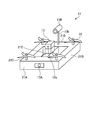
- FIG. 1 is a schematic diagram of an unmanned floating machine according to a first embodiment.
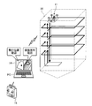
- FIG. 2 is a schematic diagram illustrating a state in which the boiler furnace according to the first embodiment is inspected.
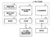
- FIG. 3 is a block configuration diagram of the indoor monitoring system for a structure according to the first embodiment.
- FIG. 4 is a block diagram of an indoor monitoring system for another structure according to the first embodiment.
- FIG. 5 is a diagram illustrating an example of a scan range when a laser scanner is used as the distance measurement unit according to the first embodiment.
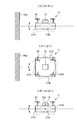
- FIG. 6 is a diagram illustrating three modes of posture positions of the unmanned floating machine according to the first embodiment.
- FIG. 7 is a horizontal position monitoring flowchart according to the first embodiment.
- FIG. 8 is a position monitoring flowchart in the height direction according to the first embodiment.
- FIG. 9 is a diagram illustrating an example of acquisition of the current position in the horizontal direction according to the first embodiment.
- FIG. 1 is a schematic diagram of an indoor monitoring system for a structure according to the first embodiment.
- FIG. 2 is a schematic diagram illustrating a state in which the boiler furnace according to the first embodiment is inspected.
- FIG. 3 is a block configuration diagram of the indoor monitoring system for a structure according to the first embodiment.
- the indoor monitoring system for a structure according to the present embodiment is a floating means that floats and moves the inside of a closed structure 50 such as a boiler furnace by remote control.
- the unmanned floating machine 11 provided with the propeller 22 and a distance measuring unit (for example, a laser scanner, an ultrasonic sensor, etc.) mounted on the unmanned floating machine 11 and measuring the distance between the unmanned floating machine 11 and the inner wall surface of the structure 50.
- a distance measuring unit for example, a laser scanner, an ultrasonic sensor, etc.
- IMU Inertial Measurement Unit
- IMU Inertial Measurement Unit
- Information (signals) and inertial measurement of an image pickup unit (still image pickup unit 13A, moving image pickup unit 13B) 13 an operation unit 15 for remotely operating the unmanned floating machine 11, and a distance measurement unit 12
- the flight position information acquisition unit 16 that acquires the current position information of the unmanned floater 11, the image information from the imaging unit 13, and the position information from the flight position information acquisition unit 16 are displayed.
- a monitor unit 14 is a laser beam emission part.
- a distance measurement step in which the distance measurement unit 12 measures horizontal distance information (r (t), ⁇ s ) between the unmanned floating aircraft 11 and the inner wall surface of the structure 50.
- the attitude angle acquisition step step S-2) of acquiring the attitude angle of the unmanned floating machine 11 by the inertial measurement unit, and the horizontal distance information using the attitude angle acquired in step 2
- the distance correction step step 3: S-3 for correcting (r (t), ⁇ s ) and the yaw angle acquired by the inertial measurement unit, at least two points (front and rear) (L f (t)) and left (L L (t)), front (L f (t)) and right (L R (t)), rear (L B (t)) and left (L L (t) ))
- a distance acquisition step step 4: S-4) for acquiring the distance between the rear (L B (t)) and the right (L R (t)), and the structure 50 is known
- a simple structure 50 such as a boiler furnace or a chimney is targeted. Since it is inside the structure 50, a distance measurement unit (for example, a laser scanner, an ultrasonic sensor, etc.) 12 that does not use GPS and an inertial measurement unit (Inertial Measurement Unit) that is a group of sensors used for controlling the attitude of the unmanned floating machine 11
- a distance measurement unit for example, a laser scanner, an ultrasonic sensor, etc.
- IMU inertial Measurement Unit
- the flight position and video of the unmanned floater 11 are displayed on the monitor unit 14 of the personal computer PC of the ground station installed outside the closed structure (boiler furnace) 50.
- the unmanned floating machine 11 is operated by the operation unit 15 while checking the damaged part), and the inner wall inspection of the closed space of the boiler furnace 50 is performed.
- the unmanned floating machine 11 is introduced from the entrance of the boiler furnace 50 shown in FIG. 2, and then the inside of the boiler furnace 50 is raised by a predetermined distance, and the operation part 15 on the ground side is operated along the inner surface of the four-direction wall. And turn. Then, it is raised again by a predetermined distance, and is similarly turned along the inner surface of the wall in the four directions. This operation is repeated until the top of the boiler furnace 50 is inspected and then lowered to finish the inspection.
- the degree of damage such as cracks in the piping on the inner surface is performed by the imaging unit.
- the monitor unit 14 can check the flight position and the damaged part, so that the position information inside can be checked by unmanned inspection. Is possible.
- the unmanned floating machine 11 is protected by a body guard part 21 (front guard part 21A, left guard part 21B, right guard part 21C, rear guard part 21D).
- Propeller 22 which is a floating means provided on the upper surface of the four corners of guard unit 21, distance measuring unit 12 mounted at the center of airframe body 21E, and still image capturing unit installed at a part of front guard unit 21A 13 ⁇ / b> A and a moving image capturing unit 13 ⁇ / b> B installed on the rear guard unit 21 ⁇ / b> D via the support unit 13 b. Since the distance measuring unit 12 scans a predetermined angle ( ⁇ 135 ° in this embodiment), it can be turned by a turning means (not shown).
- the imaging unit 13 for confirming the internal information may be either the still image capturing unit 13A or the moving image capturing unit 13B.
- FIG. 5 shows an example of the scanning range of the laser scanner.
- a scanner type range sensor “UTM-30LX (trade name)” manufactured by Hokuyo Electric Co., Ltd. was used.
- this scanner type range sensor is a two-dimensional scanning type optical distance sensor that measures the distance to a detection object while scanning with laser light, and the scan angle is ⁇ around 0 °. 135 °.
- a distance (r) is an actually measured distance from the laser scanner of the distance measuring unit 12 to the inner wall 50a, and ⁇ is an angle of the measured scan step.
- the scanning measurement step (s) in this apparatus is in increments of 0.25 °.
- FIG. 6 is a diagram illustrating three modes of posture positions of the unmanned floating machine according to the first embodiment.
- An inertial measurement unit is a device that detects three-axis angles (or angular velocities) and accelerations that control motion.
- the upper stage in FIG. 6 is a state of vertical rotation of the unmanned floating machine 11, and a turn (pitch (upward pitch)) that raises or lowers the front guard part 21 ⁇ / b> A (nose side) facing the inner wall 50 a side. ⁇ )).
- the middle stage shows the left-right rotation of the unmanned floating machine 11. The nose is shifted left and right, and the left guard part 21 ⁇ / b> B and the right guard part 21 ⁇ / b> C are swung left and right (yaw ( ⁇ )).
- the lower stage shows a state of rotation around the axis in the traveling direction of the unmanned floating machine 11, and is a turn (roll ( ⁇ )) that tilts the machine body to the left and right.
- the left and right sides of the aircraft are based on the direction of travel.
- the flight position information acquisition unit 16 calculates the true distance based on the actual distance information of the distance measurement unit 12 and the attitude angle information of the inertia measurement unit (IMU). This is because the unmanned floating aircraft 11 does not always fly according to the XY coordinates, and thus correction is necessary.
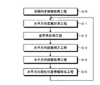
- FIG. 7 is a horizontal position monitoring flowchart according to the first embodiment.
- the measurement in the horizontal direction is performed by the first step (S-1) to the fifth step (S-5).
- an initial orientation information acquisition step (S-0) for acquiring initial orientation information when the unmanned floating machine 11 is installed in the bottom of the structure 50 is provided prior to this measurement.
- this step may be omitted.
- the first step is a horizontal distance measuring step (S-1) in which the distance measuring unit 12 measures horizontal distance information (r (t), ⁇ S ) between the unmanned floating machine 11 and the inner wall 50a of the structure 50. ).
- the second step is an attitude angle acquisition step (S-2) in which the inertial measurement unit (IMU) acquires the attitude angle of the unmanned floating machine 11.
- IMU inertial measurement unit
- the third step is a horizontal distance correction step (S-3) for correcting the horizontal distance information (r (t), ⁇ S ) using the posture angle acquired in the second step (S-2). .
- the fourth step is based on the yaw angle ( ⁇ ) acquired by the inertial measurement unit (IMU), and at least two points (front (L F (t )) And left (L L (t)), front (L F (t)) and right (L R (t)), rear (L B (t)) and left (L L (t)), rear ( This is a horizontal distance acquisition step (S-4) for acquiring the distance between L B (t)) and right (L R (t)).
- ⁇ yaw angle
- the fifth step is a horizontal direction current position information acquisition step (S-5) in which the current position information in the horizontal direction is acquired from the known cross-sectional shape information of the structure 50.
- the true distance information in the horizontal direction in consideration of the attitude angle at the time of measurement of the unmanned floating machine 11 can be acquired.
- the measurement distance is corrected with the acquired posture angle in the third step (S-3) as follows.
- the laser measurement point obtained by (r (t), ⁇ S ) is converted into (x R , y R ) coordinates. This coordinate transformation is obtained from the following equation (1).
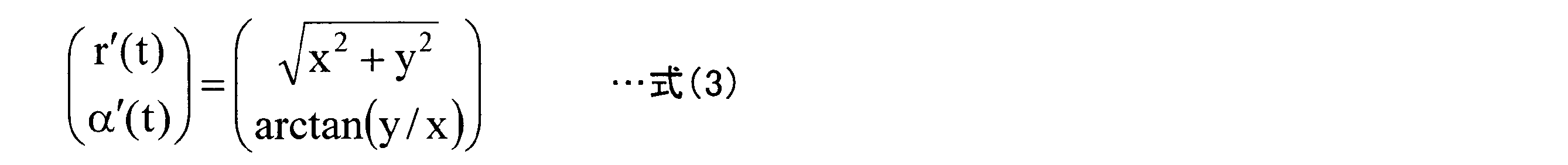
- Equation (2) The value obtained from Equation (2) is converted into the (r, ⁇ ) coordinate system of laser measurement. This coordinate transformation is obtained from the following equation (3).
- the front-rear and left-right distances of the unmanned floating machine 11 are acquired based on the yaw angle ⁇ (t) acquired by the inertial measurement unit (IMU).
- the scan angle is out of the predetermined scan range, the distance from the wall side is not adopted.
- the data of the scan angle where the scan angle ⁇ 1 ⁇ (t) is the front distance L F (t) ⁇
- the current position (x (t), y ( t)) is obtained.
- the true current position can be acquired, and the imaging information and the position information captured at the current position can be confirmed on the monitor unit 14.
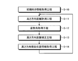
- FIG. 8 is a position monitoring flowchart in the height direction according to the first embodiment.
- the initial orientation information acquisition step (S-10) for acquiring the initial orientation information uses the information in the initial orientation information acquisition step (S-0) for acquiring the initial orientation information in the horizontal direction.
- the measurement in the height direction is performed by the following eleventh step (S-11) to fourteenth step (S-14).
- the eleventh step is a height direction distance measuring step in which the distance measuring unit 12 measures distance information (L D (t), ⁇ s ) on the lower side in the height direction of the unmanned floating machine 11 and the structure 50. (S-11).
- the measurement with the laser beam in the height direction is performed by a reflection optical system such as a mirror (not shown).
- the distance information (L U (t), ⁇ s ) on the upper side may be measured by reflecting the distance upward.
- the twelfth step is a posture angle acquisition step (S-12) in which the inertial measurement unit (IMU) acquires the posture angle of the unmanned floating machine 11.
- IMU inertial measurement unit
- the distance information (L D (t)) in the height direction is corrected using the posture angles ( ⁇ (t), ⁇ (t)) acquired in the twelfth step (S-12). This is a height direction distance correction step (S-13).
- the 14th step is a height direction current position information acquisition step (S-14) for acquiring the current position information in the height direction from the known longitudinal section shape information of the structure 50.
- the corrected measurement point (z ′ (t)) is obtained from the following equation (4).
- the horizontal direction and the height direction can be converted from the actual measurement distance to the true distance, and the position information can be acquired with certainty.
- FIG. 3 is a block diagram of the indoor monitoring system for structures according to the first embodiment.
- FIG. 4 is a block diagram of an indoor monitoring system for another structure according to the first embodiment.
- the position information processing is executed on the unmanned floating machine 11 side.
- the flight position information acquisition unit 16 is mounted at a predetermined location (not shown) on the unmanned floating aircraft 11 side, where the true current position information is acquired, and the acquired true current position information is displayed.
- the data is transmitted to the ground side by the transmission unit 13 a and displayed on the monitor unit 14.
- the unmanned floating machine 11 is operated by receiving a signal from the operation unit 15 by the receiving unit 15 a and issuing a flight command to the floating unit driving unit 19.
- the imaging information of the imaging unit 13 (still image imaging unit 13A, moving image imaging unit 13B) 13 is simultaneously transmitted on the ground side via the transmission unit 13a and displayed on the monitor unit 14. Yes.
- the position information processing is performed on the controller terminal side of the personal computer PC on the ground.
- the flight position information acquisition unit 16 is mounted on a controller terminal of a PC on the ground side (base station), and information (signal) of the distance measurement unit 12 and information (signal) of the inertia measurement unit (IMU) Is transmitted to the ground portion side by the transmitter 13a. And it is processed in the flight position information acquisition part 16 based on the received information, true current position information is acquired, and this acquired current position information is displayed on the monitor part 14.
- the imaging information captured by the imaging unit 13 is transmitted by the transmission unit 13a.
- the imaging information is temporarily transmitted to the unmanned floating machine 11 side. May be stored in the memory unit of the imaging unit, and information may be sent to the ground station after the observation is finished so that the imaging information matches the position information.
- the position information inside the structure 50 such as the boiler furnace and the chimney can be surely checked by an unmanned person, for example, labor due to the fact that no scaffolding is required, Cost and inspection period can be greatly reduced.
- the measurement by the distance measuring unit 12 is set as one point of information, but the present invention is not limited to this, and the accuracy of position measurement may be improved based on the measurement information of a plurality of points. Good.
- a plurality of points are extracted with the scan angle in the distance measuring unit 12 as the center, and the average is used as each distance. If more than half of the plurality of points become abnormal in distance measurement or become unmeasurable, they are not used for position monitoring. As a result, the influence of the distance acquisition error can be reduced.
- Unmanned floating machine 12
- Distance measuring unit laser scanner
- Imaging unit still image imaging unit 13A, moving image imaging unit 13B
- DESCRIPTION OF SYMBOLS 14
- Operation part 16
- Flight position information acquisition part 21
Landscapes
- Engineering & Computer Science (AREA)
- Radar, Positioning & Navigation (AREA)
- Remote Sensing (AREA)
- Physics & Mathematics (AREA)
- General Physics & Mathematics (AREA)
- Aviation & Aerospace Engineering (AREA)
- Automation & Control Theory (AREA)
- Chemical & Material Sciences (AREA)
- Health & Medical Sciences (AREA)
- Life Sciences & Earth Sciences (AREA)
- Analytical Chemistry (AREA)
- Biochemistry (AREA)
- General Health & Medical Sciences (AREA)
- Immunology (AREA)
- Pathology (AREA)
- Electromagnetism (AREA)
- Control Of Position, Course, Altitude, Or Attitude Of Moving Bodies (AREA)
- Studio Devices (AREA)
- Closed-Circuit Television Systems (AREA)
- Length Measuring Devices By Optical Means (AREA)
Abstract
例えばボイラ火炉等の構造物の内部を、遠隔操作により空中浮揚及び移動させる浮遊手段である例えばプロペラ(22)を備えた無人浮遊機(11)と、無人浮遊機(11)に搭載され、該無人浮遊機(11)と構造物の内壁面との距離を計測する距離計測部(12)と、この無人浮遊機(11)に搭載され、その機体姿勢を把握する慣性計測部(IMU)と、無人浮遊機(11)に搭載され、構造物の壁面側の構造体(例えば配管等)を撮像する撮像部(13)と、無人浮遊機(11)を遠隔操作する操作部と、距離計測部(12)の情報と慣性計測部の情報とにより、無人浮遊機(11)の現在位置情報を取得する飛行位置情報取得部と、撮像部(13)からの画像情報と、飛行位置情報取得部からの位置情報とを表示するモニタ部と、を備える。
Description
本発明は、構造物の屋内監視システム及び方法に関するものである。
例えば火力発電所で用いられるボイラ火炉は、製作時及び運転開始後定期的に開放し、内部に作業者が入り保守検査を行う必要がある。この保守検査時には、検査箇所を明確にする必要があるが、ボイラ火炉は容量が大きく目視で検査箇所を正確に把握することは困難である。そこで、従来では、検査箇所の高さ位置及び左右位置を巻尺等により測定マーキングすることで作業者の居場所あるいは保守検査位置を把握していたが、この方法では、作業員の足場架設やゴンドラ設置が必要となり、多大な労力、コスト及び点検期間が必要となっている。
そこで、従来では、煙突等の構造物の内部を、無人点検装置により清掃する技術が提案されている(特許文献1)。しかしながら、この提案もワイヤを設置するための架台が必要となり、その準備に労力、コスト及び点検期間が必要となっている。
また、屋外の構造物においては、無人機とGPS(Global Positioning System)とを使用した足場架設が不要の無人点検技術の適用が提案されている(特許文献2)。
しかしながら、ボイラ内部や煙突など構造物の屋内の点検では、衛星からの電波が届かないので、GPSによる飛行位置把握ができず、安定した操縦ができないため、既存の無人機による点検技術を適用することができない、という問題がある。
これに対して、GPSを使用しない屋内の飛行ができるシステムも提案されている(特許文献3)。
しかしながら、特許文献3の提案においては、GPSを用いる代わりに、地上に特徴点(又は模様)が必要であり、その特徴点(又は模様)は設置可能場所が限定される、という問題がある。また、ボイラ火炉や煙突等の構造物は内部が暗所の閉鎖空間であるので、特徴点の確認ができない、という問題がある。
よって、ボイラ火炉や煙突等の閉鎖された屋内構造物において、内部の位置情報を確実とした無人による点検が可能となり、例えば足場や架設が不要となることによる労力、コスト及び点検期間の削減ができる構造物の屋内監視システムの出現が切望されている。
本発明は、前記問題に鑑み、内部の位置情報を確実とした無人による点検が可能となり、例えば足場架設が不要となることによる労力、コスト及び点検期間の削減ができる構造物の屋内監視システム及び方法を提供することを課題とする。
上述した課題を解決するための本発明の第1の発明は、構造物の内部を、遠隔操作により空中浮揚させる浮遊手段を備えた無人浮遊機と、前記無人浮遊機に搭載され、該無人浮遊機と前記構造物の内壁面との距離を計測する距離計測部と、前記無人浮遊機に搭載され、該無人浮遊機の機体姿勢を把握する慣性計測部と、前記無人浮遊機に搭載され、前記構造物の壁面側の構造体を撮像する撮像部と、前記無人浮遊機を遠隔操作する操作部と、前記距離計測部の情報と慣性計測部の情報とにより、前記無人浮遊機の現在位置情報を取得する飛行位置情報取得部と、前記撮像部からの画像情報と、前記飛行位置情報取得部からの位置情報とを表示するモニタ部と、を備え、前記飛行位置情報取得部において、前記距離計測部により、該無人浮遊機と構造物の内壁面との水平距離情報を計測する水平方向距離計測工程と、前記慣性計測部により、無人浮遊機の姿勢角を取得する姿勢角取得工程と、前記姿勢角取得工程で取得した姿勢角を用いて前記水平距離情報を補正する水平方向距離補正工程と、前記慣性計測部で取得したヨー角を基準に、前記無人浮遊機の前後左右の少なくとも2点の距離を取得する水平方向距離取得工程と、前記構造物の既知の横断面形状情報から水平方向の現在位置情報を取得する水平方向現在位置情報取得工程とを実行することを特徴とする構造物の屋内監視システムにある。
第2の発明は、第1の発明において、前記飛行位置情報取得部において、前記距離計測部により、該無人浮遊機と構造物の上下いずれかの高さ方向の距離情報を計測する高さ方向距離計測工程と、前記慣性計測部により、無人浮遊機の姿勢角を取得する姿勢角取得工程と、前記姿勢角取得工程で取得した姿勢角を用いて前記高さ方向の距離情報を補正する高さ方向距離補正工程と、前記構造物の既知の縦断面形状情報から高さ方向の現在位置情報を取得する高さ方向現在位置情報取得工程とを実行することを特徴とする構造物の屋内監視システムにある。
第3の発明は、第1の発明において、前記水平方向距離計測工程での計測を複数点行い、平均した距離を前記水平距離情報として用いることを特徴とする構造物の屋内監視システムにある。
第4の発明は、第2の発明において、前記高さ方向距離計測工程での計測を複数点行い、平均した距離を高さ方向の距離情報として用いることを特徴とする構造物の屋内監視システムにある。
第5の発明は、第1又は2の発明において、前記飛行位置情報取得部が無人浮遊機に搭載され、取得した現在位置情報を送信部により地上部側に送信し、モニタ部で表示することを特徴とする構造物の屋内監視システムにある。
第6の発明は、第1又は2の発明において、前記飛行位置情報取得部が地上部側のコントローラ端末に搭載され、前記距離計測部の情報と慣性計測部の情報とを送信部により地上部側に送信し、前記飛行位置情報取得部において処理され、現在位置情報をモニタ部で表示することを特徴とする構造物の屋内監視システムにある。
第7の発明は、第1又は2の発明において、前記撮像部が静止画撮像部又は動画撮像部のいずれか一方又は両方であることを特徴とする構造物の屋内監視システムにある。
第8の発明は、第1又は2の発明において、前記無人浮遊機の周囲にガード部を有することを特徴とする構造物の屋内監視システムにある。
第9の発明は、構造物の内部を、遠隔操作により空中浮揚させる浮遊手段を備えた無人浮遊機を用い、前記無人浮遊機に搭載され、該無人浮遊機と前記構造物の内壁面との距離を計測する距離計測工程と、前記無人浮遊機に搭載され、該無人浮遊機の機体姿勢を把握する慣性計測工程と、前記無人浮遊機に搭載され、前記構造物の壁面側の構造体を撮像する撮像工程と、前記無人浮遊機を遠隔操作する操作工程と、前記距離計測工程の情報と慣性計測工程の情報とにより、前記無人浮遊機の現在位置情報を取得する飛行位置情報取得工程と、前記撮像工程からの画像情報と、前記飛行位置情報取得工程からの位置情報とを表示するモニタ表示工程と、を備え、前記飛行位置情報取得工程において、前記距離計測工程により、該無人浮遊機と構造物の内壁面との水平距離情報を計測する水平方向距離計測工程と、前記慣性計測工程により、無人浮遊機の姿勢角を取得する姿勢角取得工程と、前記姿勢角取得工程で取得した姿勢角を用いて前記水平距離情報を補正する水平方向距離補正工程と、前記慣性計測工程で取得したヨー角を基準に、前記無人浮遊機の前後左右の少なくとも2点の距離を取得する水平方向距離取得工程と、前記構造物の既知の横断面形状情報から水平方向の現在位置情報を取得する水平方向現在位置情報取得工程とを実行することを特徴とする構造物の屋内監視方法にある。
第10の発明は、第9の発明において、前記飛行位置情報取得工程において、前記距離計測工程により、該無人浮遊機と構造物の上下いずれかの高さ方向の距離情報を計測する高さ方向距離計測工程と、前記慣性計測工程により、無人浮遊機の姿勢角を取得する姿勢角取得工程と、前記姿勢角取得工程で取得した姿勢角を用いて前記高さ方向の距離情報を補正する高さ方向距離補正工程と、前記構造物の既知の縦断面形状情報から高さ方向の現在位置情報を取得する高さ方向現在位置情報取得工程とを実行することを特徴とする構造物の屋内監視方法にある。
第11の発明は、第9の発明において、前記水平方向距離計測工程での計測を複数点行い、平均した距離を前記水平距離情報として用いることを特徴とする構造物の屋内監視方法にある。
第12の発明は、第10の発明において、前記高さ方向距離計測工程での計測を複数点行い、平均した距離を高さ方向の距離情報として用いることを特徴とする構造物の屋内監視方法にある。
第13の発明は、第9又は10の発明において、前記飛行位置情報取得工程が無人浮遊機側で処理され、取得した現在位置情報を地上部側に送信し、モニタ表示することを特徴とする構造物の屋内監視方法にある。
第14の発明は、第9又は10の発明において、前記飛行位置情報取得工程が地上部側で処理され、前記距離計測工程の情報と慣性計測工程の情報とを地上部側に送信し、前記飛行位置情報取得工程において処理され、現在位置情報をモニタ表示することを特徴とする構造物の屋内監視方法にある。
第15の発明は、第9又は10の発明において、前記撮像工程が静止画撮像工程又は動画撮像工程のいずれか一方又は両方であることを特徴とする構造物の屋内監視方法にある。
本発明によれば、例えばボイラ火炉や煙突等の構造物の内部の位置情報を確実とした無人による点検が可能となり、例えば足場架設が不要となることによる労力、コスト及び点検期間の大幅な削減を図ることができる。
以下に添付図面を参照して、本発明の好適な実施例を詳細に説明する。なお、この実施例により本発明が限定されるものではなく、また、実施例が複数ある場合には、各実施例を組み合わせて構成するものも含むものである。
図1は、実施例1に係る構造物の屋内監視システムの概略図である。図2は、実施例1に係るボイラ火炉の点検を行う様子を示す概略図である。図3は、実施例1に係る構造物の屋内監視システムのブロック構成図である。図1乃至図3に示すように、本実施例に係る構造物の屋内監視システムは、例えばボイラ火炉等の閉鎖された構造物50の内部を、遠隔操作により空中浮揚及び移動させる浮遊手段である例えばプロペラ22を備えた無人浮遊機11と、無人浮遊機11に搭載され、該無人浮遊機11と構造物50の内壁面との距離を計測する距離計測部(例えばレーザスキャナ、超音波センサ等)12と、この無人浮遊機11に搭載され、その機体姿勢を把握する慣性計測部(Inertial Measurement Unit:IMU)と、無人浮遊機11に搭載され、構造物50の壁面側の構造体(例えば配管、継手等)を撮像する撮像部(静止画撮像部13A、動画撮像部13B)13と、無人浮遊機11を遠隔操作する操作部15と、距離計測部12の情報(信号)と慣性計測部の情報(信号)とにより、無人浮遊機11の現在位置情報を取得する飛行位置情報取得部16と、撮像部13からの画像情報と、飛行位置情報取得部16からの位置情報とを表示するモニタ部14と、を備えている。なお、12aはレーザ光出射部である。
そして、飛行位置情報取得部16において、距離計測部12により、該無人浮遊機11と構造物50の内壁面との水平距離情報(r(t)、αs)を計測する距離計測工程(工程1:S-1)と、慣性計測部により、無人浮遊機11の姿勢角を取得する姿勢角取得工程(工程2:S-2)と、工程2で取得した姿勢角を用いて水平距離情報(r(t)、αs)を補正する距離補正工程(工程3:S-3)と、慣性計測部で取得したヨー角を基準に、無人浮遊機11の前後左右の少なくとも2点(前(Lf(t))と左(LL(t))、前(Lf(t))と右(LR(t))、後(LB(t))と左(LL(t))、後(LB(t))と右(LR(t))のいずれか2点)の距離を取得する距離取得工程(工程4:S-4)と、構造物50の既知の横断面形状情報から水平方向の現在位置情報を取得する水平方向現在位置情報取得工程(工程5:S-5)とを実行するようにしている。
本実施例では、例えばボイラ火炉、煙突等の単純形状(断面形状が矩形、円形)の構造物50を対象としている。構造物50の内部であるので、GPSを使用しない距離計測部(例えばレーザスキャナ、超音波センサ等)12と、無人浮遊機11の機体姿勢制御に使用するセンサ群である慣性計測部(Inertial Measurement Unit:IMU)を用いて、無人浮遊機11の飛行位置(現在飛行位置情報)をモニタリングするシステムを提供する。
本実施例では、図2に示すように、閉鎖された構造物(ボイラ火炉)50の外部に設置する地上ステーションのパーソナルコンピュータPCのモニタ部14にて、無人浮遊機11の飛行位置や映像(損傷個所)を確認しながら、操作部15にて、無人浮遊機11を操作し、ボイラ火炉50の閉鎖空間の内壁検査を行うようにしている。
検査は、図2に示すボイラ火炉50の入口から無人浮遊機11を導入し、その後ボイラ火炉50内を所定距離上昇させ、地上側の操作部15の操作により、4方向の壁の内面に沿って旋回させる。その後、再び所定距離上昇させ、同様に4方向の壁の内面に沿って旋回させる。この操作を繰り返して、ボイラ火炉50の頂上まで検査した後、降下させて、検査を終了する。
検査は、内面の配管の亀裂等の損傷の程度を撮像部により行っている。この検査の際、閉鎖された屋内構造物において、本実施例によれば、モニタ部14において、飛行位置及び損傷個所の確認を行うことができるので、内部の位置情報を確実とした無人による点検が可能となる。
検査は、内面の配管の亀裂等の損傷の程度を撮像部により行っている。この検査の際、閉鎖された屋内構造物において、本実施例によれば、モニタ部14において、飛行位置及び損傷個所の確認を行うことができるので、内部の位置情報を確実とした無人による点検が可能となる。
無人浮遊機11は、図1に示すように、機体ガード部21(前方側ガード部21A、左側ガード部21B、右側ガード部21C、後方側ガード部21D)により周囲が防護されており、この機体ガード部21の四隅の上面に設けた浮遊手段であるプロペラ22と、機体本体21Eの中心部に搭載された距離計測部12と、前方側ガード部21Aの一部に設置された静止画撮像部13Aと、後方側ガード部21Dに支持部13bを介して設置された動画撮像部13Bと、を備えている。なお、距離計測部12は、所定角(本実施例では±135°)スキャンするので、図示しない旋回手段により旋回可能としている。
ここで、内部情報を確認する撮像部13としては、静止画撮像部13A又は動画撮像部13Bのいずれか一方であってもよい。
以下、本実施例においては、距離計測部12として、レーザスキャナを使用した場合の位置モニタリングの手順について、説明する。
<水平方向のモニタリング>
(1)水平方向のモニタリングを実施するには、先ず距離計測部12で距離(r(t)、αs)を取得する。
ここで、図5にレーザスキャナのスキャンの範囲の一例を示す。本実施例では、北陽電機社製のスキャナ式レンジセンサ「UTM-30LX(商品名)」を用いて行った。
(1)水平方向のモニタリングを実施するには、先ず距離計測部12で距離(r(t)、αs)を取得する。
ここで、図5にレーザスキャナのスキャンの範囲の一例を示す。本実施例では、北陽電機社製のスキャナ式レンジセンサ「UTM-30LX(商品名)」を用いて行った。
図5に示すように、このスキャナ式レンジセンサは、レーザ光でスキャンニングしながら検出物までの距離を測定する二次元走査型の光距離センサであり、スキャン角度が、0°を中心として±135°である。
図5において、距離(r)は、距離計測部12のレーザスキャナから内壁50aまでの計測時点での実測距離であり、αはその計測したスキャンステップの角度である。本装置でのスキャンの計測ステップ(s)は0.25°刻みとなっている。
図5において、距離(r)は、距離計測部12のレーザスキャナから内壁50aまでの計測時点での実測距離であり、αはその計測したスキャンステップの角度である。本装置でのスキャンの計測ステップ(s)は0.25°刻みとなっている。
(2)次に、慣性計測部(IMU)において、無人浮遊機11の姿勢角ピッチ角(θ(t))、ヨー角(ψ(t))、ロール角(φ(t))を取得する。
図6は、実施例1に係る無人浮遊機の姿勢位置の3態様を示す図である。
慣性計測部(IMU)は、運動を司る3軸の角度(または角速度)と加速度を検出する装置である。
慣性計測部(IMU)は、運動を司る3軸の角度(または角速度)と加速度を検出する装置である。
ここで、図6中、上段は、無人浮遊機11の上下回転の様子であり、内壁50a側に向いている前方側ガード部21A(機首側)を上げたり、下げたりする旋回(ピッチ(θ))である。図6中、中段は、無人浮遊機11の機体の左右回転の様子であり、機首の向きを左右にずらし、左側ガード部21Bと右側ガード部21Cとが左右にふれる旋回(ヨー(ψ))である。図6中、下段は、無人浮遊機11の進行方向の軸まわりの回転の様子であり、機体を左右に傾ける旋回(ロール(φ))である。なお、機体の左右は進行方向を基準としている。
次に、位置モニタリング計測工程について、図3を参照して説明する。
飛行位置情報取得部16では、距離計測部12の実距離情報と、慣性計測部(IMU)の姿勢角情報とに基づき、真の距離を求めるものである。これは、無人浮遊機11は常にXY座標通りに飛行できるとは限らないので、補正をする必要があるからである。
飛行位置情報取得部16では、距離計測部12の実距離情報と、慣性計測部(IMU)の姿勢角情報とに基づき、真の距離を求めるものである。これは、無人浮遊機11は常にXY座標通りに飛行できるとは限らないので、補正をする必要があるからである。
図7は、実施例1に係る水平方向の位置モニタリングフロー図である。
水平方向の計測は第1工程(S-1)~第5工程(S-5)により行われる。
なお、本実施例では、この計測に先立って、構造物50の内部に無人浮遊機11を底部に設置した際の初期向き情報を取得する初期向き情報取得工程(S-0)を設けているが、この工程は、省略するようにしてもよい。
水平方向の計測は第1工程(S-1)~第5工程(S-5)により行われる。
なお、本実施例では、この計測に先立って、構造物50の内部に無人浮遊機11を底部に設置した際の初期向き情報を取得する初期向き情報取得工程(S-0)を設けているが、この工程は、省略するようにしてもよい。
1)第1工程は、距離計測部12により、無人浮遊機11と構造物50の内壁50aとの水平距離情報(r(t)、αS)を計測する水平方向距離計測工程(S-1)である。
2)第2工程は、慣性計測部(IMU)により、無人浮遊機11の姿勢角を取得する姿勢角取得工程(S-2)である。
3)第3工程は、第2工程(S-2)で取得した姿勢角を用いて水平距離情報(r(t)、αS)を補正する水平方向距離補正工程(S-3)である。
4)第4工程は、図9に示すように、慣性計測部(IMU)で取得したヨー角(ψ)を基準に、無人浮遊機11の前後左右の少なくとも2点(前(LF(t))と左(LL(t))、前(LF(t))と右(LR(t))、後(LB(t))と左(LL(t))、後(LB(t))と右(LR(t))のいずれか2点)の距離を取得する水平方向距離取得工程(S-4)である。
5)第5工程は、構造物50の既知の横断面形状情報から水平方向の現在位置情報を取得する水平方向現在位置情報取得工程(S-5)である。
この第1工程(S-1)~第5工程(S-5)を実行することで、無人浮遊機11の計測時の姿勢角を考慮した水平方向の真の距離情報を取得することができる。
ここで、第3工程(S-3)における取得した姿勢角で計測距離を補正するのは以下のように行う。
(r(t)、αS)で得られるレーザ計測点を(xR,yR)座標に変換する。この座標変換は、下記式(1)から求められる。
(r(t)、αS)で得られるレーザ計測点を(xR,yR)座標に変換する。この座標変換は、下記式(1)から求められる。

補正後の計測点(x’(t)、y’(t))の、回転座標系の変換は、下記式(2)から求められる。

式(2)から求めた値を、レーザ計測の(r、α)座標系に変換する。この座標変換は、下記式(3)から求められる。
次に、第4工程(S-4)において、慣性計測部(IMU)で取得したヨー角ψ(t)を基準に、無人浮遊機11の前後左右の距離を取得する。ただし、スキャン角が所定のスキャン範囲を外れた場合は、壁側からの距離としては、採用しない。
・スキャン角α1=ψ(t)となるスキャン角のデータを正面距離LF(t)
・スキャン角α2=ψ(t)-90°となるスキャン角を左側距離LL(t)
・スキャン角α3=ψ(t)+90°となるスキャン角を右側距離LR(t)
・スキャン角α4=ψ(t)+180°となるスキャン角を後方距離LB(t)
・スキャン角α1=ψ(t)となるスキャン角のデータを正面距離LF(t)
・スキャン角α2=ψ(t)-90°となるスキャン角を左側距離LL(t)
・スキャン角α3=ψ(t)+90°となるスキャン角を右側距離LR(t)
・スキャン角α4=ψ(t)+180°となるスキャン角を後方距離LB(t)
最後の第5工程(S-5)において、計測可能な距離(最低2つ:前後左右の各々の少なくとも2点)を使って、既知の横断面形状から現在位置(x(t),y(t))を取得する。
これにより真の現在位置を取得することができ、この現在の位置において撮影した撮像情報と、位置情報とをモニタ部14で確認することができる。
この位置情報の計測を無人浮遊機11が移動する毎に計測することで、連続した位置情報の把握が確実に行うことができる。
<高さ方向のモニタリング>
図8は、実施例1に係る高さ方向の位置モニタリングフロー図である。
初期向き情報を取得する初期向き情報取得工程(S-10)は、水平方向での初期向き情報を取得する初期向き情報取得工程(S-0)での情報を用いる。
高さ方向の計測は、以下の第11工程(S-11)~第14工程(S-14)により行われる。
図8は、実施例1に係る高さ方向の位置モニタリングフロー図である。
初期向き情報を取得する初期向き情報取得工程(S-10)は、水平方向での初期向き情報を取得する初期向き情報取得工程(S-0)での情報を用いる。
高さ方向の計測は、以下の第11工程(S-11)~第14工程(S-14)により行われる。
6)第11工程は、距離計測部12により、無人浮遊機11と構造物50の高さ方向の下方側の距離情報(LD(t)、αs)を計測する高さ方向距離計測工程(S-11)である。
ここで、高さ方向のレーザ光による計測は、図示しないミラー等の反射光学系により行う。レーザ光の照射距離が上昇するにつれて届かない場合には、上方側に反射させて上方側の距離情報(LU(t)、αs)を計測するようにしてもよい。
ここで、高さ方向のレーザ光による計測は、図示しないミラー等の反射光学系により行う。レーザ光の照射距離が上昇するにつれて届かない場合には、上方側に反射させて上方側の距離情報(LU(t)、αs)を計測するようにしてもよい。
7)第12工程は、慣性計測部(IMU)により、無人浮遊機11の姿勢角を取得する姿勢角取得工程(S-12)である。
8)第13工程は、第12工程(S-12)で取得した姿勢角(φ(t),θ(t))を用いて高さ方向の距離情報(LD(t))を補正する高さ方向距離補正工程(S-13)である。
9)第14工程は、構造物50の既知の縦断面形状情報から高さ方向の現在位置情報を取得する高さ方向現在位置情報取得工程(S-14)である。
第13工程(S-13)の補正は、補正後の計測点(z’ (t))を、下記式(4)から求める。
以上より、水平方向と高さ方向とが実計測距離から真の距離に変換することができ、位置情報を確実に取得することができる。
この結果、GPSが使用できない構造物50の屋内での無人機による計測位置を確実に把握する点検が可能となる。この結果、従来のような構造物50の内部に足場や架設の設置が不要となり、内部検査のための労力、コストおよび点検期間の大幅な削減が可能となる。
図3は、実施例1に係る構造物の屋内監視システムのブロック構成図である。図4は、実施例1に係る他の構造物の屋内監視システムのブロック構成図である。
図3に示すように、本実施例では、位置情報処理を無人浮遊機11側で実行する場合である。
本実施例では、飛行位置情報取得部16が無人浮遊機11側の所定箇所(図示せず)に搭載され、ここで、真の現在位置情報を取得し、この取得した真の現在位置情報を送信部13aにより地上部側に送信し、モニタ部14で表示するようにしている。
なお、無人浮遊機11の操作は、操作部15からの信号を受信部15aで受け、浮遊機駆動部19に飛行の指令を出している。
本実施例では、飛行位置情報取得部16が無人浮遊機11側の所定箇所(図示せず)に搭載され、ここで、真の現在位置情報を取得し、この取得した真の現在位置情報を送信部13aにより地上部側に送信し、モニタ部14で表示するようにしている。
なお、無人浮遊機11の操作は、操作部15からの信号を受信部15aで受け、浮遊機駆動部19に飛行の指令を出している。
また、本実施例では、撮像部13(静止画撮像部13A、動画撮像部13B)13の撮像情報を、同時に送信部13aを介して地上側の送信し、モニタ部14で表示するようにしている。
これに対して、図4に示す他の実施例では、位置情報処理を地上部のパーソナルコンピュータPCのコントローラ端末側にある場合である。
本実施例では、飛行位置情報取得部16が地上部側(基地局)のPCのコントローラ端末に搭載され、距離計測部12の情報(信号)と慣性計測部(IMU)の情報(信号)とを送信部13aにより地上部側に送信する。そして、受信した情報を基に飛行位置情報取得部16において処理され、真の現在位置情報を取得し、この取得した現在位置情報をモニタ部14で表示するようにしている。
本実施例では、飛行位置情報取得部16が地上部側(基地局)のPCのコントローラ端末に搭載され、距離計測部12の情報(信号)と慣性計測部(IMU)の情報(信号)とを送信部13aにより地上部側に送信する。そして、受信した情報を基に飛行位置情報取得部16において処理され、真の現在位置情報を取得し、この取得した現在位置情報をモニタ部14で表示するようにしている。
本実施例では、撮像部13で撮像した撮像情報を送信部13aで送るようにしているが、本発明では、これに限定されるものではなく、例えば撮像情報を一時的に無人浮遊機11側の撮像部のメモリ部に格納しておき、観察終了後に、地上ステーション側に情報を送って、撮像情報と位置情報とを合致させるようにしてもよい。
以上説明したように、本実施例によれば、例えばボイラ火炉や煙突等の構造物50の内部の位置情報を確実とした無人による点検が可能となり、例えば足場架設が不要となることによる労力、コスト及び点検期間の大幅な削減を図ることができる。
実施例1においては、距離計測部12での計測を一点の情報としているが、本発明はこれに限定されず、複数点の計測情報を基にして位置計測の精度を向上させるようにしてもよい。
すなわち、水平方向及び高さ方向の距離計算において、距離計測部12でのスキャン角を中心として複数点を抽出し、平均したものをそれぞれの距離とする。そして、この複数点のうち、半数以上が距離計測異常又は計測不能となった場合は、位置モニタリングに使用しないようにする。
この結果、距離取得誤差の影響を低減することができる。
この結果、距離取得誤差の影響を低減することができる。
11 無人浮遊機
12 距離計測部(レーザスキャナ)
13 撮像部(静止画撮像部13A、動画撮像部13B)
14 モニタ部
15 操作部
16 飛行位置情報取得部
21 機体ガード部
22 プロペラ
50 構造物
12 距離計測部(レーザスキャナ)
13 撮像部(静止画撮像部13A、動画撮像部13B)
14 モニタ部
15 操作部
16 飛行位置情報取得部
21 機体ガード部
22 プロペラ
50 構造物
Claims (15)
- 構造物の内部を、遠隔操作により空中浮揚させる浮遊手段を備えた無人浮遊機と、
前記無人浮遊機に搭載され、該無人浮遊機と前記構造物の内壁面との距離を計測する距離計測部と、
前記無人浮遊機に搭載され、該無人浮遊機の機体姿勢を把握する慣性計測部と、
前記無人浮遊機に搭載され、前記構造物の壁面側の構造体を撮像する撮像部と、
前記無人浮遊機を遠隔操作する操作部と、
前記距離計測部の情報と慣性計測部の情報とにより、前記無人浮遊機の現在位置情報を取得する飛行位置情報取得部と、
前記撮像部からの画像情報と、前記飛行位置情報取得部からの位置情報とを表示するモニタ部と、を備え、
前記飛行位置情報取得部において、
前記距離計測部により、該無人浮遊機と構造物の内壁面との水平距離情報を計測する水平方向距離計測工程と、
前記慣性計測部により、無人浮遊機の姿勢角を取得する姿勢角取得工程と、
前記姿勢角取得工程で取得した姿勢角を用いて前記水平距離情報を補正する水平方向距離補正工程と、
前記慣性計測部で取得したヨー角を基準に、前記無人浮遊機の前後左右の少なくとも2点の距離を取得する水平方向距離取得工程と、
前記構造物の既知の横断面形状情報から水平方向の現在位置情報を取得する水平方向現在位置情報取得工程とを実行することを特徴とする構造物の屋内監視システム。 - 請求項1において、
前記飛行位置情報取得部において、
前記距離計測部により、該無人浮遊機と構造物の上下いずれかの高さ方向の距離情報を計測する高さ方向距離計測工程と、
前記慣性計測部により、無人浮遊機の姿勢角を取得する姿勢角取得工程と、
前記姿勢角取得工程で取得した姿勢角を用いて前記高さ方向の距離情報を補正する高さ方向距離補正工程と、
前記構造物の既知の縦断面形状情報から高さ方向の現在位置情報を取得する高さ方向現在位置情報取得工程とを実行することを特徴とする構造物の屋内監視システム。 - 請求項1において、
前記水平方向距離計測工程での計測を複数点行い、平均した距離を前記水平距離情報として用いることを特徴とする構造物の屋内監視システム。 - 請求項2において、
前記高さ方向距離計測工程での計測を複数点行い、平均した距離を高さ方向の距離情報として用いることを特徴とする構造物の屋内監視システム。 - 請求項1又は2において、
前記飛行位置情報取得部が無人浮遊機に搭載され、取得した現在位置情報を送信部により地上部側に送信し、モニタ部で表示することを特徴とする構造物の屋内監視システム。 - 請求項1又は2において、
前記飛行位置情報取得部が地上部側のコントローラ端末に搭載され、
前記距離計測部の情報と慣性計測部の情報とを送信部により地上部側に送信し、前記飛行位置情報取得部において処理され、現在位置情報をモニタ部で表示することを特徴とする構造物の屋内監視システム。 - 請求項1又は2において、
前記撮像部が静止画撮像部又は動画撮像部のいずれか一方又は両方であることを特徴とする構造物の屋内監視システム。 - 請求項1又は2において、
前記無人浮遊機の周囲にガード部を有することを特徴とする構造物の屋内監視システム。 - 構造物の内部を、遠隔操作により空中浮揚させる浮遊手段を備えた無人浮遊機を用い、
前記無人浮遊機に搭載され、該無人浮遊機と前記構造物の内壁面との距離を計測する距離計測工程と、
前記無人浮遊機に搭載され、該無人浮遊機の機体姿勢を把握する慣性計測工程と、
前記無人浮遊機に搭載され、前記構造物の壁面側の構造体を撮像する撮像工程と、
前記無人浮遊機を遠隔操作する操作工程と、
前記距離計測工程の情報と慣性計測工程の情報とにより、前記無人浮遊機の現在位置情報を取得する飛行位置情報取得工程と、
前記撮像工程からの画像情報と、前記飛行位置情報取得工程からの位置情報とを表示するモニタ表示工程と、を備え、
前記飛行位置情報取得工程において、
前記距離計測工程により、該無人浮遊機と構造物の内壁面との水平距離情報を計測する水平方向距離計測工程と、
前記慣性計測工程により、無人浮遊機の姿勢角を取得する姿勢角取得工程と、
前記姿勢角取得工程で取得した姿勢角を用いて前記水平距離情報を補正する水平方向距離補正工程と、
前記慣性計測工程で取得したヨー角を基準に、前記無人浮遊機の前後左右の少なくとも2点の距離を取得する水平方向距離取得工程と、
前記構造物の既知の横断面形状情報から水平方向の現在位置情報を取得する水平方向現在位置情報取得工程とを実行することを特徴とする構造物の屋内監視方法。 - 請求項9において、
前記飛行位置情報取得工程において、
前記距離計測工程により、該無人浮遊機と構造物の上下いずれかの高さ方向の距離情報を計測する高さ方向距離計測工程と、
前記慣性計測工程により、無人浮遊機の姿勢角を取得する姿勢角取得工程と、
前記姿勢角取得工程で取得した姿勢角を用いて前記高さ方向の距離情報を補正する高さ方向距離補正工程と、
前記構造物の既知の縦断面形状情報から高さ方向の現在位置情報を取得する高さ方向現在位置情報取得工程とを実行することを特徴とする構造物の屋内監視方法。 - 請求項9において、
前記水平方向距離計測工程での計測を複数点行い、平均した距離を前記水平距離情報として用いることを特徴とする構造物の屋内監視方法。 - 請求項10において、
前記高さ方向距離計測工程での計測を複数点行い、平均した距離を高さ方向の距離情報として用いることを特徴とする構造物の屋内監視方法。 - 請求項9又は10において、
前記飛行位置情報取得工程が無人浮遊機側で処理され、取得した現在位置情報を地上部側に送信し、モニタ表示することを特徴とする構造物の屋内監視方法。 - 請求項9又は10において、
前記飛行位置情報取得工程が地上部側で処理され、
前記距離計測工程の情報と慣性計測工程の情報とを地上部側に送信し、前記飛行位置情報取得工程において処理され、現在位置情報をモニタ表示することを特徴とする構造物の屋内監視方法。 - 請求項9又は10において、
前記撮像工程が静止画撮像工程又は動画撮像工程のいずれか一方又は両方であることを特徴とする構造物の屋内監視方法。
Priority Applications (3)
| Application Number | Priority Date | Filing Date | Title |
|---|---|---|---|
| CN201580034665.7A CN106662880B (zh) | 2014-07-02 | 2015-01-20 | 构造物的屋内监视系统以及方法 |
| US15/322,230 US10359778B2 (en) | 2014-07-02 | 2015-01-20 | Indoor monitoring system and method for structure |
| EP15814504.5A EP3147743B1 (en) | 2014-07-02 | 2015-01-20 | Indoor monitoring system and method for structure |
Applications Claiming Priority (2)
| Application Number | Priority Date | Filing Date | Title |
|---|---|---|---|
| JP2014-136868 | 2014-07-02 | ||
| JP2014136868A JP6486024B2 (ja) | 2014-07-02 | 2014-07-02 | 構造物の屋内監視システム及び方法 |
Publications (1)
| Publication Number | Publication Date |
|---|---|
| WO2016002236A1 true WO2016002236A1 (ja) | 2016-01-07 |
Family
ID=55018806
Family Applications (1)
| Application Number | Title | Priority Date | Filing Date |
|---|---|---|---|
| PCT/JP2015/051360 Ceased WO2016002236A1 (ja) | 2014-07-02 | 2015-01-20 | 構造物の屋内監視システム及び方法 |
Country Status (6)
| Country | Link |
|---|---|
| US (1) | US10359778B2 (ja) |
| EP (1) | EP3147743B1 (ja) |
| JP (1) | JP6486024B2 (ja) |
| CN (1) | CN106662880B (ja) |
| TW (1) | TWI578132B (ja) |
| WO (1) | WO2016002236A1 (ja) |
Cited By (3)
| Publication number | Priority date | Publication date | Assignee | Title |
|---|---|---|---|---|
| WO2018158927A1 (ja) * | 2017-03-02 | 2018-09-07 | エスゼット ディージェイアイ テクノロジー カンパニー リミテッド | 3次元形状推定方法、飛行体、モバイルプラットフォーム、プログラム及び記録媒体 |
| US20220097845A1 (en) * | 2019-02-27 | 2022-03-31 | Mitsubishi Power, Ltd. | Unmanned aerial vehicle and inspection method |
| JP2022156984A (ja) * | 2021-03-31 | 2022-10-14 | 関西電力株式会社 | データ取得装置および該方法 |
Families Citing this family (30)
| Publication number | Priority date | Publication date | Assignee | Title |
|---|---|---|---|---|
| WO2017138049A1 (ja) * | 2016-02-10 | 2017-08-17 | パナソニックIpマネジメント株式会社 | 飛行体及びその制御システム |
| WO2017169516A1 (ja) * | 2016-03-28 | 2017-10-05 | 日本電気株式会社 | 無人飛行装置制御システム、無人飛行装置制御方法および検査装置 |
| JP6710114B2 (ja) * | 2016-06-21 | 2020-06-17 | 株式会社日立製作所 | 管路施設点検飛行体と、それを用いた管路施設点検システム |
| JP6697821B2 (ja) * | 2016-07-21 | 2020-05-27 | 三菱重工機械システム株式会社 | 画像処理装置および画像処理方法 |
| JP6746137B2 (ja) * | 2016-11-02 | 2020-08-26 | 株式会社プロドローン | 無人航空機 |
| CN106500611A (zh) * | 2016-11-25 | 2017-03-15 | 重庆科技学院 | 测距仪辅助装置 |
| JP2018116443A (ja) * | 2017-01-18 | 2018-07-26 | 住友重機械工業株式会社 | 検査システム |
| JP6868303B2 (ja) * | 2017-03-12 | 2021-05-12 | 株式会社ナイルワークス | 圃場の水深測定用ドローン |
| JP6822267B2 (ja) * | 2017-03-28 | 2021-01-27 | 富士通株式会社 | 飛翔機及び飛翔機の使用方法 |
| JP6729879B2 (ja) * | 2017-04-06 | 2020-07-29 | 株式会社自律制御システム研究所 | 無人航空機、及びこれを用いる方法 |
| TWI662505B (zh) * | 2017-07-28 | 2019-06-11 | 中華大學 | 菌類生長影像監控系統 |
| CN109561275A (zh) * | 2017-09-27 | 2019-04-02 | 湖南航天远望科技有限公司 | 一种基于圆周扫描的区域监控方法及区域监控系统 |
| WO2019064456A1 (ja) * | 2017-09-28 | 2019-04-04 | 株式会社オプティム | メンテナンス用機器制御システム、メンテナンス用機器制御方法およびプログラム |
| JP7063578B2 (ja) * | 2017-11-09 | 2022-05-09 | 株式会社Soken | 飛行装置 |
| JP6475377B1 (ja) * | 2018-03-14 | 2019-02-27 | 株式会社サンメイ | 煙突の内部を検査する検査システム、および煙突の内部を検査する方法 |
| JP7033969B2 (ja) * | 2018-03-19 | 2022-03-11 | 三菱重工業株式会社 | 無人飛行体 |
| CN109031312B (zh) * | 2018-04-26 | 2023-08-22 | 中国计量大学 | 适用于烟囱内部作业的飞行平台定位装置和定位方法 |
| JP6505927B1 (ja) * | 2018-07-24 | 2019-04-24 | ミスギ工業株式会社 | 無人小型飛行体を用いた点検方法及びこれに用いる無人小型飛行体 |
| JP2020094780A (ja) * | 2018-12-14 | 2020-06-18 | 三菱重工機械システム株式会社 | 煙突筒身内面点検システム |
| SG11202100153SA (en) * | 2018-12-27 | 2021-02-25 | Performance Rotors Pte Ltd | Drone for surface defects inspection |
| JP6733925B2 (ja) * | 2019-03-27 | 2020-08-05 | ミスギ工業株式会社 | 無人小型飛行体を用いた点検方法及びこれに用いる無人小型飛行体 |
| JP6737521B2 (ja) * | 2019-08-27 | 2020-08-12 | 株式会社センシンロボティクス | 高さ位置取得システム及び撮像システム、高さ位置取得方法、撮像方法 |
| JP6604681B1 (ja) | 2019-09-11 | 2019-11-13 | 株式会社Liberaware | 寸法表示システムおよび寸法表示方法 |
| JP6715542B1 (ja) * | 2019-10-28 | 2020-07-01 | 株式会社センシンロボティクス | 飛行体、点検方法及び点検システム |
| JP6777804B1 (ja) * | 2019-11-22 | 2020-10-28 | 三菱パワー株式会社 | ボイラ内部検査方法 |
| JP2021066420A (ja) * | 2020-06-02 | 2021-04-30 | 株式会社センシンロボティクス | 飛行体、点検方法及び点検システム |
| JP7612149B2 (ja) * | 2020-12-24 | 2025-01-14 | 株式会社Liberaware | 製鉄用加熱炉の検査方法 |
| CN112729312A (zh) * | 2020-12-25 | 2021-04-30 | 云南电网有限责任公司昆明供电局 | 一种变电站高压室无人机巡视方法 |
| CN113483616B (zh) * | 2021-07-06 | 2023-03-14 | 重庆市地质矿产勘查开发局208水文地质工程地质队(重庆市地质灾害防治工程勘查设计院) | 用于地表裂缝的便携式快速装拆精准监测仪 |
| JP7594753B2 (ja) * | 2023-05-17 | 2024-12-05 | 国立大学法人徳島大学 | 円筒構造体の点検システム |
Citations (8)
| Publication number | Priority date | Publication date | Assignee | Title |
|---|---|---|---|---|
| JP2007213190A (ja) * | 2006-02-08 | 2007-08-23 | Advanced Telecommunication Research Institute International | コミュニケーションロボット改良システム |
| JP2009136987A (ja) * | 2007-12-10 | 2009-06-25 | Toyota Motor Corp | 移動ロボット、及び床面形状データの補正方法 |
| JP2009294713A (ja) * | 2008-06-02 | 2009-12-17 | Sanyo Electric Co Ltd | 点検システム、制御装置、点検方法及び制御プログラム |
| JP2010079869A (ja) * | 2008-08-25 | 2010-04-08 | Murata Machinery Ltd | 自律移動装置 |
| JP2012509812A (ja) * | 2008-11-27 | 2012-04-26 | パロット | 無人機を操縦する装置 |
| JP2012228944A (ja) * | 2011-04-26 | 2012-11-22 | Chiba Inst Of Technology | マルチロータヘリコプタの横風安定化装置及びこれを備えたマルチロータヘリコプタ |
| JP2013531573A (ja) * | 2010-05-26 | 2013-08-08 | エアロヴァイロンメント インコーポレイテッド | 再構成可能なバッテリ式の無人機システム |
| JP2014119828A (ja) * | 2012-12-13 | 2014-06-30 | Secom Co Ltd | 自律飛行ロボット |
Family Cites Families (19)
| Publication number | Priority date | Publication date | Assignee | Title |
|---|---|---|---|---|
| JP3153832B2 (ja) | 1992-08-26 | 2001-04-09 | 三菱重工業株式会社 | 煙突の清掃装置 |
| JP2001209426A (ja) * | 2000-01-26 | 2001-08-03 | Nippon Telegr & Teleph Corp <Ntt> | 移動体制御装置 |
| JP2004211995A (ja) * | 2003-01-07 | 2004-07-29 | Mitsubishi Heavy Ind Ltd | 密閉空間内検査システム |
| CA2484422A1 (en) | 2004-10-08 | 2006-04-08 | Furgro Airborne Surveys | Unmanned airborne vehicle for geophysical surveying |
| EP1901153A1 (en) | 2006-09-12 | 2008-03-19 | OFFIS e.V. | Control system for unmanned 4-rotor-helicopter |
| JP2009093308A (ja) * | 2007-10-05 | 2009-04-30 | Hitachi Industrial Equipment Systems Co Ltd | ロボットシステム |
| JP5105596B2 (ja) * | 2007-10-30 | 2012-12-26 | 株式会社Ihi | 自律走行移動体の走行経路決定用地図作成装置及び走行経路決定用地図作成方法 |
| JP5349804B2 (ja) * | 2008-01-10 | 2013-11-20 | 株式会社日立産機システム | 移動ロボットシステム及びその制御方法 |
| US8060270B2 (en) | 2008-02-29 | 2011-11-15 | The Boeing Company | System and method for inspection of structures and objects by swarm of remote unmanned vehicles |
| US20140061376A1 (en) | 2010-05-26 | 2014-03-06 | Aerovironment Inc | Reconfigurable battery-operated vehicle system |
| CN102435188B (zh) * | 2011-09-15 | 2013-10-02 | 南京航空航天大学 | 一种用于室内环境的单目视觉/惯性全自主导航方法 |
| CN202600150U (zh) | 2012-05-17 | 2012-12-12 | 北京必威易激光科技有限公司 | 智能化低空遥感测绘系统 |
| CN103455036B (zh) | 2012-06-05 | 2018-04-27 | 国家电网公司 | 一种场景空中巡视方法和飞行器 |
| CN103144770B (zh) * | 2013-03-19 | 2015-10-28 | 南京航空航天大学 | 一种全自主控制入室环境避障导航微型飞行器 |
| CN103365295B (zh) | 2013-06-29 | 2015-09-30 | 天津大学 | 基于dsp的四旋翼无人飞行器自主悬停控制系统及方法 |
| CN203342367U (zh) | 2013-07-01 | 2013-12-18 | 昊翔电能运动科技(昆山)有限公司 | 多轴飞行器 |
| CN103365298B (zh) * | 2013-07-05 | 2017-06-20 | 深圳市大疆创新科技有限公司 | 无人飞行器的飞行辅助系统和方法 |
| CN103697889B (zh) | 2013-12-29 | 2016-05-25 | 北京航空航天大学 | 一种基于多模型分布式滤波的无人机自主导航与定位方法 |
| WO2015107623A1 (ja) * | 2014-01-15 | 2015-07-23 | パイオニア株式会社 | 管理システム及び位置特定方法 |
-
2014
- 2014-07-02 JP JP2014136868A patent/JP6486024B2/ja active Active
-
2015
- 2015-01-20 EP EP15814504.5A patent/EP3147743B1/en active Active
- 2015-01-20 CN CN201580034665.7A patent/CN106662880B/zh active Active
- 2015-01-20 US US15/322,230 patent/US10359778B2/en active Active
- 2015-01-20 WO PCT/JP2015/051360 patent/WO2016002236A1/ja not_active Ceased
- 2015-01-27 TW TW104102689A patent/TWI578132B/zh active
Patent Citations (8)
| Publication number | Priority date | Publication date | Assignee | Title |
|---|---|---|---|---|
| JP2007213190A (ja) * | 2006-02-08 | 2007-08-23 | Advanced Telecommunication Research Institute International | コミュニケーションロボット改良システム |
| JP2009136987A (ja) * | 2007-12-10 | 2009-06-25 | Toyota Motor Corp | 移動ロボット、及び床面形状データの補正方法 |
| JP2009294713A (ja) * | 2008-06-02 | 2009-12-17 | Sanyo Electric Co Ltd | 点検システム、制御装置、点検方法及び制御プログラム |
| JP2010079869A (ja) * | 2008-08-25 | 2010-04-08 | Murata Machinery Ltd | 自律移動装置 |
| JP2012509812A (ja) * | 2008-11-27 | 2012-04-26 | パロット | 無人機を操縦する装置 |
| JP2013531573A (ja) * | 2010-05-26 | 2013-08-08 | エアロヴァイロンメント インコーポレイテッド | 再構成可能なバッテリ式の無人機システム |
| JP2012228944A (ja) * | 2011-04-26 | 2012-11-22 | Chiba Inst Of Technology | マルチロータヘリコプタの横風安定化装置及びこれを備えたマルチロータヘリコプタ |
| JP2014119828A (ja) * | 2012-12-13 | 2014-06-30 | Secom Co Ltd | 自律飛行ロボット |
Non-Patent Citations (3)
| Title |
|---|
| DILL, E.; ET AL.: "Seamless indoor-outdoor navigation for unmanned multi-sensor aerial platforms", POSITION, LOCATION AND NAVIGATION SYMPOSIUM - PLANS 2014, 5 May 2015 (2015-05-05), pages 1174 - 1182, XP032616416 * |
| See also references of EP3147743A4 * |
| SEUNGHO JEONG; ET AL.: "Vision-based localization of a quad-rotor system", UBIQUITOUS ROBOTS AND AMBIENT INTELLIGENCE (URAI), 2012 9TH INTERNATIONAL CONFERENCE ON, 26 November 2012 (2012-11-26), pages 636 - 638, XP032331135 * |
Cited By (4)
| Publication number | Priority date | Publication date | Assignee | Title |
|---|---|---|---|---|
| WO2018158927A1 (ja) * | 2017-03-02 | 2018-09-07 | エスゼット ディージェイアイ テクノロジー カンパニー リミテッド | 3次元形状推定方法、飛行体、モバイルプラットフォーム、プログラム及び記録媒体 |
| US20220097845A1 (en) * | 2019-02-27 | 2022-03-31 | Mitsubishi Power, Ltd. | Unmanned aerial vehicle and inspection method |
| JP2022156984A (ja) * | 2021-03-31 | 2022-10-14 | 関西電力株式会社 | データ取得装置および該方法 |
| JP7602952B2 (ja) | 2021-03-31 | 2024-12-19 | 関西電力株式会社 | データ取得装置および該方法 |
Also Published As
| Publication number | Publication date |
|---|---|
| CN106662880B (zh) | 2019-08-06 |
| CN106662880A (zh) | 2017-05-10 |
| JP6486024B2 (ja) | 2019-03-20 |
| TW201602748A (zh) | 2016-01-16 |
| US20170139410A1 (en) | 2017-05-18 |
| TWI578132B (zh) | 2017-04-11 |
| EP3147743B1 (en) | 2019-04-03 |
| EP3147743A4 (en) | 2017-05-31 |
| US10359778B2 (en) | 2019-07-23 |
| EP3147743A1 (en) | 2017-03-29 |
| JP2016015628A (ja) | 2016-01-28 |
Similar Documents
| Publication | Publication Date | Title |
|---|---|---|
| JP6486024B2 (ja) | 構造物の屋内監視システム及び方法 | |
| JP7260269B2 (ja) | 航空非破壊検査用の測位システム | |
| CN108303426B (zh) | 一种电缆隧道缺陷无损快速检测装置及其检测方法 | |
| US20190113937A1 (en) | Measuring device, control device for unmanned aerial vehicle and computer program product for controlling unmanned aerial vehicle | |
| JP2019078746A (ja) | ケーブル懸架式プラットフォームを用いた構造体を測定及び検査するための方法 | |
| JP2016111414A (ja) | 飛行体の位置検出システム及び飛行体 | |
| JP6039050B1 (ja) | 無人機を用いた構造物等の検査方法 | |
| WO2017065102A1 (ja) | 飛行型検査装置および検査方法 | |
| CN112327898B (zh) | 无人机的井道巡检导航方法、装置和无人机 | |
| JP2017059955A (ja) | 撮像システム及びコンピュータプログラム | |
| JP2017201757A (ja) | 画像取得システム、画像取得方法、画像処理方法 | |
| JP6499542B2 (ja) | 構造物の点検方法 | |
| JP7026272B1 (ja) | 飛行体ユニットおよび点検システム | |
| US20230103063A1 (en) | Hammering test system | |
| KR102504743B1 (ko) | 시설물의 모델링을 기반으로 하는 점검 드론의 위치 보정장치 및 보정방법 | |
| JP2023070120A (ja) | 自律飛行制御方法、自律飛行制御装置および自律飛行制御システム | |
| KR102572904B1 (ko) | 무인 항공기 및 검사 방법 | |
| US20250150559A1 (en) | Moving wind turbine blade inspection | |
| JP7314466B2 (ja) | 無人航空機、画像撮像システム、及びプログラム | |
| JP6715542B1 (ja) | 飛行体、点検方法及び点検システム | |
| KR101956472B1 (ko) | 구조물 검사 장치 및 밸러스트 탱크 검사 시스템 | |
| JP2021170283A (ja) | 建築物検査装置 | |
| JP7165800B2 (ja) | 撮影画像補正方法 | |
| KR101990202B1 (ko) | 구조물 검사 장치 및 밸러스트 탱크 검사 시스템 |
Legal Events
| Date | Code | Title | Description |
|---|---|---|---|
| 121 | Ep: the epo has been informed by wipo that ep was designated in this application |
Ref document number: 15814504 Country of ref document: EP Kind code of ref document: A1 |
|
| REEP | Request for entry into the european phase |
Ref document number: 2015814504 Country of ref document: EP |
|
| WWE | Wipo information: entry into national phase |
Ref document number: 2015814504 Country of ref document: EP |
|
| WWE | Wipo information: entry into national phase |
Ref document number: 15322230 Country of ref document: US |
|
| NENP | Non-entry into the national phase |
Ref country code: DE |