WO2016002262A1 - Capteur piézoélectrique et élément piézoélectrique - Google Patents
Capteur piézoélectrique et élément piézoélectrique Download PDFInfo
- Publication number
- WO2016002262A1 WO2016002262A1 PCT/JP2015/057866 JP2015057866W WO2016002262A1 WO 2016002262 A1 WO2016002262 A1 WO 2016002262A1 JP 2015057866 W JP2015057866 W JP 2015057866W WO 2016002262 A1 WO2016002262 A1 WO 2016002262A1
- Authority
- WO
- WIPO (PCT)
- Prior art keywords
- piezoelectric
- detection electrode
- electrode
- terminal electrode
- piezoelectric element
- Prior art date
- Legal status (The legal status is an assumption and is not a legal conclusion. Google has not performed a legal analysis and makes no representation as to the accuracy of the status listed.)
- Ceased
Links
Images


Classifications
-
- B—PERFORMING OPERATIONS; TRANSPORTING
- B60—VEHICLES IN GENERAL
- B60C—VEHICLE TYRES; TYRE INFLATION; TYRE CHANGING; CONNECTING VALVES TO INFLATABLE ELASTIC BODIES IN GENERAL; DEVICES OR ARRANGEMENTS RELATED TO TYRES
- B60C23/00—Devices for measuring, signalling, controlling, or distributing tyre pressure or temperature, specially adapted for mounting on vehicles; Arrangement of tyre inflating devices on vehicles, e.g. of pumps or of tanks; Tyre cooling arrangements
- B60C23/06—Signalling devices actuated by deformation of the tyre, e.g. tyre mounted deformation sensors or indirect determination of tyre deformation based on wheel speed, wheel-centre to ground distance or inclination of wheel axle
- B60C23/064—Signalling devices actuated by deformation of the tyre, e.g. tyre mounted deformation sensors or indirect determination of tyre deformation based on wheel speed, wheel-centre to ground distance or inclination of wheel axle comprising tyre mounted deformation sensors, e.g. to determine road contact area
-
- G—PHYSICS
- G01—MEASURING; TESTING
- G01L—MEASURING FORCE, STRESS, TORQUE, WORK, MECHANICAL POWER, MECHANICAL EFFICIENCY, OR FLUID PRESSURE
- G01L17/00—Devices or apparatus for measuring tyre pressure or the pressure in other inflated bodies
-
- G—PHYSICS
- G01—MEASURING; TESTING
- G01L—MEASURING FORCE, STRESS, TORQUE, WORK, MECHANICAL POWER, MECHANICAL EFFICIENCY, OR FLUID PRESSURE
- G01L9/00—Measuring steady of quasi-steady pressure of fluid or fluent solid material by electric or magnetic pressure-sensitive elements; Transmitting or indicating the displacement of mechanical pressure-sensitive elements, used to measure the steady or quasi-steady pressure of a fluid or fluent solid material, by electric or magnetic means
- G01L9/0041—Transmitting or indicating the displacement of flexible diaphragms
- G01L9/0076—Transmitting or indicating the displacement of flexible diaphragms using photoelectric means
-
- G—PHYSICS
- G01—MEASURING; TESTING
- G01L—MEASURING FORCE, STRESS, TORQUE, WORK, MECHANICAL POWER, MECHANICAL EFFICIENCY, OR FLUID PRESSURE
- G01L9/00—Measuring steady of quasi-steady pressure of fluid or fluent solid material by electric or magnetic pressure-sensitive elements; Transmitting or indicating the displacement of mechanical pressure-sensitive elements, used to measure the steady or quasi-steady pressure of a fluid or fluent solid material, by electric or magnetic means
- G01L9/08—Measuring steady of quasi-steady pressure of fluid or fluent solid material by electric or magnetic pressure-sensitive elements; Transmitting or indicating the displacement of mechanical pressure-sensitive elements, used to measure the steady or quasi-steady pressure of a fluid or fluent solid material, by electric or magnetic means by making use of piezoelectric devices, i.e. electric circuits therefor
-
- H—ELECTRICITY
- H10—SEMICONDUCTOR DEVICES; ELECTRIC SOLID-STATE DEVICES NOT OTHERWISE PROVIDED FOR
- H10N—ELECTRIC SOLID-STATE DEVICES NOT OTHERWISE PROVIDED FOR
- H10N30/00—Piezoelectric or electrostrictive devices
- H10N30/30—Piezoelectric or electrostrictive devices with mechanical input and electrical output, e.g. functioning as generators or sensors
- H10N30/302—Sensors
-
- H—ELECTRICITY
- H10—SEMICONDUCTOR DEVICES; ELECTRIC SOLID-STATE DEVICES NOT OTHERWISE PROVIDED FOR
- H10N—ELECTRIC SOLID-STATE DEVICES NOT OTHERWISE PROVIDED FOR
- H10N30/00—Piezoelectric or electrostrictive devices
- H10N30/80—Constructional details
- H10N30/87—Electrodes or interconnections, e.g. leads or terminals
- H10N30/871—Single-layered electrodes of multilayer piezoelectric or electrostrictive devices, e.g. internal electrodes
-
- B—PERFORMING OPERATIONS; TRANSPORTING
- B60—VEHICLES IN GENERAL
- B60C—VEHICLE TYRES; TYRE INFLATION; TYRE CHANGING; CONNECTING VALVES TO INFLATABLE ELASTIC BODIES IN GENERAL; DEVICES OR ARRANGEMENTS RELATED TO TYRES
- B60C19/00—Tyre parts or constructions not otherwise provided for
- B60C2019/004—Tyre sensors other than for detecting tyre pressure
Definitions
- the present invention relates to a piezoelectric sensor and a piezoelectric element.
- a piezoelectric sensor for detecting deflection for example, a piezoelectric sensor described in Japanese Patent Application Laid-Open No. 2007-163230 (Patent Document 1) is known.
- a thin film piezoelectric material such as aluminum nitride is formed on one main surface of a film-like flat plate made of a polymer material such as polyimide having flexibility, and the piezoelectric material is formed. It is comprised by providing an electrode layer in both the main surfaces of a flat plate.
- This piezoelectric sensor is extremely thin and flexible, and is used in close contact with a curved surface such as the inner surface of a tire. As a result, it is possible to detect deformation of the tire due to variations in tire air pressure.
- the piezoelectric sensor described in the publication has a thin-film piezoelectric body, and is used by being directly attached to a tire with an adhesive. Therefore, it was easy to detect various signals such as external impact and vibration directly transmitted from the tire, in addition to the signal due to the deformation of the tire due to the fluctuation of the air pressure. Therefore, in order to accurately detect only deformation due to air pressure fluctuation, a complicated signal processing circuit is required.
- peripheral circuit devices such as a signal processing circuit attached around the piezoelectric sensor are connected by a large number of lead wires. It was. As a result, the number of wires inside the tire is large, and the wires are long and complicated, making it difficult to mount and use other electronic components (such as ICs).
- a film-like piezoelectric sensor can have a very thin structure
- the area of the piezoelectric sensor itself has to be increased and the size thereof must be increased. For this reason, when a sharp object such as a nail is pierced into the tire, there is a high possibility that the piezoelectric sensor itself or the peripheral circuit device will be damaged, and when it is damaged, the deformation of the tire cannot be detected.
- the piezoelectric sensor of the present invention includes a substrate and a piezoelectric element, the substrate has a mounting electrode formed on one main surface, and the piezoelectric element includes a laminate and a laminate.
- the laminated body includes a piezoelectric body, and a first detection electrode and a second detection electrode provided so as to sandwich the piezoelectric body.
- an exterior body laminated on at least one outer side wherein the first detection electrode is connected to the first terminal electrode, the second detection electrode is connected to the second terminal electrode, and the first terminal electrode and the first The two-terminal electrodes were respectively bonded to the mounting electrodes with a bonding agent so that the piezoelectric element was mounted on the substrate.
- the first detection electrode is pulled out from one end face of the laminate and two side faces in contact with the end face and connected to the first terminal electrode.
- the second detection electrode is connected to the other end face of the laminate and It is preferable to draw out from two side surfaces in contact with the end surface and connect to the second terminal electrode. In this case, the connection between the detection electrode and the terminal electrode is ensured.
- a gap is formed between the substrate and the piezoelectric element.
- the gap suppresses the piezoelectric sensor from detecting noise such as external impact or vibration transmitted directly from the tire or the like, it is possible to detect the deflection of the substrate with high sensitivity.
- the gap may be filled with rubber or resin. In this case, the bonding strength between the substrate and the piezoelectric element is improved.
- the present invention is also directed to piezoelectric elements.
- the piezoelectric element includes a multilayer body, and a first terminal electrode and a second terminal electrode provided on different end surfaces of the multilayer body, and the multilayer body sandwiches the piezoelectric body and the piezoelectric body.
- a piezoelectric sensor that has high sensitivity, is difficult to detect noise such as vibration, can be easily downsized, and can easily integrate peripheral circuits by modularization.
- FIG. 1 is a side view showing a piezoelectric sensor according to Embodiment 1.
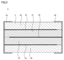
- FIG. 3 is a cross-sectional view of a main part of a piezoelectric element of the piezoelectric sensor according to Embodiment 1.
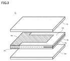
- FIG. 1 is an exploded perspective view of a main part of a piezoelectric sensor according to a first embodiment. It is explanatory drawing which shows the case where the piezoelectric sensor concerning Embodiment 1 is installed in the tire. It is explanatory drawing which showed typically the deformation
- FIG. 1 is a side view showing a piezoelectric sensor according to Embodiment 1.
- FIG. 3 is a cross-sectional view of a main part of a piezoelectric element of the piezoelectric sensor according to Embodiment 1.
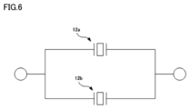
- FIG. 3 is an equivalent circuit diagram of the piezoelectric sensor according to the first embodiment.
- 6 is a side view of a piezoelectric sensor according to a second embodiment.
- FIG. It is explanatory drawing which showed typically the deformation
- FIG. 1 shows a piezoelectric sensor 100 according to the first embodiment.
- the piezoelectric sensor 100 includes a substrate 10 and a piezoelectric element 11 mounted on the substrate 10.
- the piezoelectric element 11 has a rectangular parallelepiped shape, and includes a stacked body 17, and first terminal electrodes 15 a and second terminal electrodes 15 b provided on both end faces of the stacked body 17.
- the first terminal electrode 15a and the second terminal electrode 15b are mounted on the substrate 10 by solders 19a and 19b, which are bonding materials, respectively.
- a gap 13 corresponding to the mounting height is formed.
- the laminated body 17 of the piezoelectric elements 11 includes, in order from the top, an exterior body 14a, a first detection electrode 16a, a piezoelectric body 12a, a second detection electrode 16b, a piezoelectric body 12b, and a first detection body.
- the electrode 16c and the outer package 14b are laminated and integrated.
- the piezoelectric body 12b on which the first detection electrode 16c is formed and the exterior body 14b are bonded and integrated with an adhesive (not shown).
- the piezoelectric bodies 12a and 12b are made of, for example, a ceramic material having piezoelectricity. Moreover, the exterior bodies 14a and 14b are formed of an insulating material such as a ceramic material such as magnesium titanate or a resin material such as glass epoxy. Each of the piezoelectric bodies 12a and 12b and the exterior bodies 14a and 14b has a rectangular flat plate shape. The piezoelectric bodies 12a and 12b are each subjected to polarization treatment.
- a structure in which the upper and lower main surfaces of the piezoelectric bodies 12a and 12b are held by the exterior bodies 14a and 14b is adopted.
- the displacement of the piezoelectric bodies 12a and 12b in the thickness direction is suppressed, even when an impact with acceleration is applied, detection of acceleration can be suppressed and deflection can be detected more accurately.
- the other main surface may be partially held, and the holding of the other main surface may be omitted.
- outer casings 14a and 14b having higher Young's modulus than piezoelectric bodies 12a and 12b.
- the first detection electrodes 16a and 16c are drawn out from one end face of the multilayer body 17 and two side faces following the both sides.
- the second detection electrode 16b is drawn to the outside from the other end face of the multilayer body 17 and two side faces that follow both sides thereof.
- the first detection electrodes 16 a and 16 c and the second detection electrode 16 b are each drawn out from the three surfaces of the stacked body 17 in a T shape.
- the electrical connection reliability is high.
- the second detection electrode 16b and the second terminal electrode 15b are connected not only at the end face but also at a part of the side face, the electrical connection reliability is high.
- the layered body 17 has a structure other than the connection portion with the first terminal electrode 15a and the second terminal electrode 15b. Not exposed to the outer surface. Therefore, it is not easily affected by the external environment such as moisture.
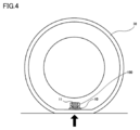
- FIG. 4 shows a state where the piezoelectric sensor 100 attached to the tire 38 on the substrate 10 side detects the deformation of the tire.
- the piezoelectric sensor 100 mainly detects the deflection of the substrate caused by the deformation of the tire 38 due to air pressure fluctuation or the deformation of the tire in the road surface state.
- the tire 38 when the tire 38 is grounded to the ground, the tire 38 is deformed, so that the substrate 10 bends vertically upward from the ground, and the deflection causes the piezoelectric element 11 to vertically upward from the ground. Bend.
- the amount of deflection of the substrate 10 and the piezoelectric element 11 depends on the amount of deformation of the tire 38.
- the tire 38 rotates in accordance with the progress of the mounted automobile or the like, and the portion where the piezoelectric sensor 100 is mounted is periodically grounded. Therefore, the piezoelectric sensor 100 can detect periodic tire deformation.
- the piezoelectric element 11 is mounted on the substrate 10 at two locations, a first terminal electrode 15a and a second terminal electrode 15b.
- the size of the substrate 10 is larger than the size of the piezoelectric element 11. Therefore, in the piezoelectric sensor 100, the deflection of the substrate 10 is amplified and the piezoelectric element 11 is bent. Then, the magnitude of the deflection of the piezoelectric element 11 is detected as an electrical signal from the first detection electrodes 16a and 16b and the second detection electrode 16b.
- the piezoelectric sensor 100 has high sensitivity because the deflection of the substrate 10 is amplified and the piezoelectric element 11 bends, and the deflection of the piezoelectric element 11 is detected as an electric signal.
- the piezoelectric sensor 100 has a gap 13 between the substrate 10 and the piezoelectric element 11.
- the gap 13 functions to prevent the piezoelectric sensor 100 from detecting noise such as external impact or vibration transmitted directly from the tire 38.
- the piezoelectric sensor 100 can detect only deflection with high sensitivity without detecting noise such as external impact and vibration.
- the piezoelectric sensor 100 Since the piezoelectric sensor 100 has high sensitivity, it can be formed in a small size. In addition, by mounting other electronic components on the substrate 10, it is easy to integrate peripheral circuits into a module.
- FIG. 5A shows a state in which no deflection is applied to the piezoelectric sensor 100.
- the piezoelectric sensor as in this embodiment is often used in an environment where severe temperature changes occur. For this reason, a phenomenon in which charges are generated by heat, that is, pyroelectricity, may occur, and the charges generated by the pyroelectricity may be mixed with the charges generated by the deflection. Therefore, it is preferable to reduce the influence of pyroelectricity.
- the terminal electrodes 15a and 15b and the detection electrodes 16a, 16b and 16c are provided, and detection is performed in two layers. 6 is configured so as not to be affected by pyroelectricity. In other words, this circuit cancels out the electric charge caused by pyroelectricity by connecting the two layers of detection parts in parallel. Therefore, it is possible to detect only the electric charge due to the deflection.
- the deformation as shown in FIG. 5B occurs in the piezoelectric sensor 100 when the deflection is acting.
- a tensile stress Pt is generated in the piezoelectric bodies 12a and 12b.
- the side on which the detection electrode 16a is provided and the side on which the detection electrode 16b is provided are positive (+) and negative (based on the relationship between the polarization direction and the tensile stress Pt ( -) Is generated.
- the side on which the detection electrode 16b is provided and the side on which the detection electrode 16c is provided are positive and negative based on the relationship between the polarization direction and the tensile stress Pt. Charge is generated.
- the piezoelectric sensor 100 according to the first embodiment having the above structure can be manufactured, for example, according to the following procedure.
- the detection electrodes 16a and 16b are formed on the piezoelectric body 12a such as ceramic, and the detection electrode 16c is formed on the piezoelectric body 12b such as ceramic by screen printing.
- a polarization process is performed in which the polarization direction becomes a desired direction.
- an adhesive such as an epoxy resin is applied to both main surfaces of the integrally fired piezoelectric bodies 12a and 12b, and the exterior body 14a, the piezoelectric bodies 12a and 12b, and the exterior body 14b are laminated and integrally joined. . Thereby, the laminated body 17 is produced.
- terminal electrodes 15a and 15b are formed by forming a thin film such as Ag on the both end faces of the laminated body 17 by sputtering or the like, and performing metal plating on the thin film. Thereby, the piezoelectric element 11 is obtained.
- the piezoelectric element 100 is completed by mounting the piezoelectric element 11 on the substrate 10 with solder.
- the first detection electrode and the second detection electrode are T-shaped, but it is not always necessary to make such a configuration.
- other shapes such as an I-shape are used. Can do.
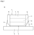
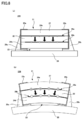
- FIG. 7 shows a piezoelectric sensor 200 according to the second embodiment.
- the piezoelectric sensor 200 includes a piezoelectric element 21 including a single piezoelectric body 22 instead of the piezoelectric element 11 of the first embodiment.
- the piezoelectric element 21 includes a multilayer body 27, and a first terminal electrode 25a and a second terminal electrode 25b.
- the laminated body 27 includes an exterior body 24a, a first detection electrode 26a, a piezoelectric body 22, a second detection electrode 26b, and an exterior body 24b stacked in order from the top. It consists of the structure made.
- the first terminal electrode 25a and the second terminal electrode 25b are mounted on the substrate 20 by solders 29a and 29b, which are bonding materials, respectively.
- a gap 23 corresponding to the mounting height is formed.
- the outer body 24a, the piezoelectric body 22 in which the first detection electrode 26a is formed on one main surface and the second detection electrode 26b is formed on the other main surface, and the outer body 24b are bonded and integrated by an adhesive (not shown).
- the piezoelectric sensor 200 composed of the above has fewer piezoelectric bodies and detection electrodes, so that the piezoelectric sensor 200 can be easily produced at low cost.
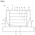
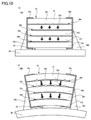
- FIG. 9 shows a piezoelectric sensor 300 according to the third embodiment.
- the piezoelectric sensor 300 includes a piezoelectric element 31 including three piezoelectric bodies 32a, 32b, and 32c instead of the piezoelectric element 11 of the first embodiment.
- the piezoelectric element 31 includes a stacked body 37, a first terminal electrode 35a, and a second terminal electrode 35b.
- the laminated body 37 includes, in order from the top, an exterior body 34a, a first detection electrode 36a, a piezoelectric body 32a, a second detection electrode 36b, a piezoelectric body 32b, and a first detection electrode.
- 36c, the piezoelectric body 32c, the second detection electrode 36d, and the exterior body 34b are stacked and integrated.
- the first terminal electrode 35a and the second terminal electrode 35b are mounted on the substrate 30 by solders 39a and 39b, which are bonding materials, respectively.
- a gap 33 corresponding to the height of the mounting is formed.
- the piezoelectric body 32b in which the first detection electrode 36c is formed, the piezoelectric body 32c in which the first detection electrode 36d is formed on one main surface, and the exterior body 34b are formed by an adhesive (not shown). Bonded and integrated.
- the piezoelectric bodies 32a, 32b, and 32c are each subjected to polarization treatment.
- the piezoelectric body 32b sandwiched between the piezoelectric bodies 32a and 32c does not function as a piezoelectric body, the piezoelectric body 32b can be an unpolarized piezoelectric body or an insulator.
- the piezoelectric sensor 300 can cancel the electric charge by pyroelectricity similarly to the piezoelectric sensor 100 according to the first embodiment.
- the piezoelectric element 31 is taller than the piezoelectric sensor 100 according to the first embodiment by the amount of the piezoelectric body 32b. For this reason, when the substrate 30 bends to the same extent as the substrate 10 of the first embodiment, the deflection of the piezoelectric body 32a becomes larger than that of the piezoelectric body 12a. Thereby, the sensitivity which detects a deflection
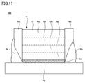
- FIG. 11 shows a piezoelectric sensor 400 according to the fourth embodiment.
- the gap 43 of the piezoelectric sensor 100 according to the first embodiment is filled with a resin 43.
- a resin 43 a silicone-based resin, rubber, or the like can be used.
- the bonding strength between the substrate 40 and the piezoelectric element 41 is improved as compared with the piezoelectric sensors 100, 200, and 300 according to the first to third embodiments.
- the piezoelectric sensor includes a substrate and a piezoelectric element.
- the substrate has a pair of mounting electrodes formed on one main surface.
- the piezoelectric element includes a laminate, and a first terminal electrode and a second terminal electrode provided on different end surfaces of the laminate.
- the laminated body includes a piezoelectric body, a first detection electrode and a second detection electrode provided so as to sandwich the piezoelectric body, and an outer side of at least one of the first detection electrode and the second detection electrode. And an insulating exterior body laminated on the substrate.
- the first detection electrode is connected to the first terminal electrode, and the second detection electrode is connected to the second terminal electrode.
- the first terminal electrode is bonded to one of the pair of mounting electrodes by a bonding material, and the second terminal electrode is bonded to the other of the pair of mounting electrodes by a bonding material. Thereby, the piezoelectric element is mounted on the substrate.
- the first detection electrode may be connected to the first terminal electrode by being pulled out from one end surface of the laminate and two side surfaces in contact with the end surface.
- the second detection electrode may be connected to the second terminal electrode by being drawn out from the other end face of the laminate and two side faces in contact with the end face.
- a gap may be formed between the substrate and the piezoelectric element.
- rubber or resin may be filled between the substrate and the piezoelectric element.
- the piezoelectric element includes a laminate, and a first terminal electrode and a second terminal electrode provided on different end surfaces of the laminate.
- the laminated body includes a piezoelectric body, a first detection electrode and a second detection electrode provided so as to sandwich the piezoelectric body, and an outer side of at least one of the first detection electrode and the second detection electrode. And an insulating exterior body laminated on the substrate.
- the first detection electrode is connected to the first terminal electrode
- the second detection electrode is connected to the second terminal electrode.
- Piezoelectric sensor 10 20, 30, 40 Substrate, 11, 21, 31, 41 Piezoelectric element, 12a, 12b, 22, 32a, 32b, 32c, 42a, 42b Piezoelectric body, 14a, 14b 24a, 24b, 34a, 34b, 44a, 44b exterior body, 15a, 15b, 25a, 25b, 35a, 35b, 45a, 45b terminal electrode, 16a, 16b, 16c, 26a, 26b, 36a, 36b, 36c, 36d 46a, 46b, 46c, electrode for detection, 17, 27, 37, 47 laminate, 38 tire, 19a, 19b, 29a, 29b, 39a, 39b, 49a, 49b solder, 13, 23, 33 gap, 43 resin.
Landscapes
- Physics & Mathematics (AREA)
- General Physics & Mathematics (AREA)
- Engineering & Computer Science (AREA)
- Mechanical Engineering (AREA)
- Measuring Fluid Pressure (AREA)
- Force Measurement Appropriate To Specific Purposes (AREA)
Abstract
L'invention concerne un capteur piézoélectrique (100) pourvu d'un substrat (10) et d'un élément piézoélectrique (11). Le substrat (10) est pourvu d'au moins une paire d'électrodes de montage sur une surface principale de celui-ci. L'élément piézoélectrique (11) est pourvu d'un stratifié (17), d'une première électrode de borne (15a) et d'une seconde électrode de borne (15b). La première électrode de borne (15a) et la seconde électrode de borne (15b) sont liées respectivement aux électrodes de montage au moyen de matériaux de liaison (19a, 19b).
Priority Applications (3)
| Application Number | Priority Date | Filing Date | Title |
|---|---|---|---|
| JP2016531136A JP6252678B2 (ja) | 2014-07-04 | 2015-03-17 | 圧電センサおよび圧電素子 |
| CN201580033288.5A CN106461486B (zh) | 2014-07-04 | 2015-03-17 | 压电传感器及压电元件 |
| US15/386,148 US10232674B2 (en) | 2014-07-04 | 2016-12-21 | Piezoelectric sensor and piezoelectric element |
Applications Claiming Priority (2)
| Application Number | Priority Date | Filing Date | Title |
|---|---|---|---|
| JP2014-138751 | 2014-07-04 | ||
| JP2014138751 | 2014-07-04 |
Related Child Applications (1)
| Application Number | Title | Priority Date | Filing Date |
|---|---|---|---|
| US15/386,148 Continuation US10232674B2 (en) | 2014-07-04 | 2016-12-21 | Piezoelectric sensor and piezoelectric element |
Publications (1)
| Publication Number | Publication Date |
|---|---|
| WO2016002262A1 true WO2016002262A1 (fr) | 2016-01-07 |
Family
ID=55018823
Family Applications (1)
| Application Number | Title | Priority Date | Filing Date |
|---|---|---|---|
| PCT/JP2015/057866 Ceased WO2016002262A1 (fr) | 2014-07-04 | 2015-03-17 | Capteur piézoélectrique et élément piézoélectrique |
Country Status (4)
| Country | Link |
|---|---|
| US (1) | US10232674B2 (fr) |
| JP (1) | JP6252678B2 (fr) |
| CN (1) | CN106461486B (fr) |
| WO (1) | WO2016002262A1 (fr) |
Cited By (2)
| Publication number | Priority date | Publication date | Assignee | Title |
|---|---|---|---|---|
| CN107026230A (zh) * | 2016-01-29 | 2017-08-08 | Tdk株式会社 | 压电致动器 |
| JP2022159314A (ja) * | 2018-12-17 | 2022-10-17 | アルプスアルパイン株式会社 | タイヤセンサモジュールおよびタイヤセンサ装置 |
Families Citing this family (8)
| Publication number | Priority date | Publication date | Assignee | Title |
|---|---|---|---|---|
| CN106461486B (zh) * | 2014-07-04 | 2019-06-28 | 株式会社村田制作所 | 压电传感器及压电元件 |
| JP2018173343A (ja) * | 2017-03-31 | 2018-11-08 | セイコーエプソン株式会社 | 力検出装置およびロボット |
| CN112236657A (zh) * | 2018-07-06 | 2021-01-15 | 欧姆龙株式会社 | 应变传感器和拉伸特性测定方法 |
| WO2020131539A1 (fr) * | 2018-12-21 | 2020-06-25 | Bridgestone Americas Tire Operations, Llc | Système de détection de déviation de pneu |
| CN109696458B (zh) * | 2019-02-19 | 2024-04-26 | 泰安博联物联网科技有限公司 | 基于利用压电检测法的正负x面检测装置及检测方法 |
| AU2021224844A1 (en) * | 2020-02-21 | 2022-10-20 | Nitto Bend Technologies, Inc. | Tire and tire sensor |
| CN112124013A (zh) * | 2020-08-25 | 2020-12-25 | 江苏理工学院 | 一种基于压电发电材料的智能轮胎测试系统及测试方法 |
| US12459311B2 (en) * | 2021-10-30 | 2025-11-04 | Tdk Corporation | Devices and methods for overloading protection of piezoelectric material mounted on wheels |
Citations (4)
| Publication number | Priority date | Publication date | Assignee | Title |
|---|---|---|---|---|
| JP2000114912A (ja) * | 1998-09-30 | 2000-04-21 | Murata Mfg Co Ltd | 圧電部品 |
| JP2007315958A (ja) * | 2006-05-26 | 2007-12-06 | Tdk Corp | 加速度センサおよび加速度センサの製造方法 |
| JP2011525046A (ja) * | 2008-06-19 | 2011-09-08 | エプコス アクチエンゲゼルシャフト | 圧電素子、及び電気的接続の形成方法 |
| JP2013101020A (ja) * | 2011-11-08 | 2013-05-23 | Seiko Epson Corp | センサー素子、力検出装置およびロボット |
Family Cites Families (16)
| Publication number | Priority date | Publication date | Assignee | Title |
|---|---|---|---|---|
| JPH0663725B2 (ja) | 1985-12-27 | 1994-08-22 | ダイキン工業株式会社 | 圧電センサ |
| US5786655A (en) * | 1994-05-26 | 1998-07-28 | Canon Kabushiki Kaisha | Strain element and vibration device |
| DE10026005B4 (de) * | 2000-05-25 | 2004-07-08 | Robert Bosch Gmbh | Piezoaktor |
| US6664716B2 (en) * | 2000-06-07 | 2003-12-16 | Purdue Research Foundation | Piezoelectric transducer |
| US6800986B2 (en) * | 2002-01-23 | 2004-10-05 | Tdk Corporation | Piezoelectric sensor |
| JP2004128386A (ja) * | 2002-10-07 | 2004-04-22 | Nec Tokin Corp | 積層型圧電セラミックス素子 |
| JP4427665B2 (ja) | 2004-07-28 | 2010-03-10 | 国立大学法人広島大学 | 曲げ変形センサおよび変形測定装置 |
| JP2006048302A (ja) | 2004-08-03 | 2006-02-16 | Sony Corp | 圧電複合装置、その製造方法、その取扱方法、その制御方法、入出力装置及び電子機器 |
| JP2007010377A (ja) * | 2005-06-28 | 2007-01-18 | Kyocera Corp | 加速度センサ |
| JP5168681B2 (ja) | 2005-12-12 | 2013-03-21 | 独立行政法人産業技術総合研究所 | タイヤ空気圧センサおよびタイヤ空気圧監視装置 |
| JP6016228B2 (ja) * | 2012-07-03 | 2016-10-26 | ソニーセミコンダクタソリューションズ株式会社 | センサデバイス |
| JP2014052263A (ja) * | 2012-09-06 | 2014-03-20 | Nippon Dempa Kogyo Co Ltd | 外力検出装置及び外力検出センサー |
| CN105247331A (zh) * | 2013-05-01 | 2016-01-13 | 索尼公司 | 传感器装置和电子设备 |
| CN106461486B (zh) * | 2014-07-04 | 2019-06-28 | 株式会社村田制作所 | 压电传感器及压电元件 |
| CN107208999B (zh) * | 2015-02-18 | 2019-07-23 | 株式会社村田制作所 | 压电传感器 |
| JP2018129629A (ja) * | 2017-02-07 | 2018-08-16 | セイコーエプソン株式会社 | 圧電センサー及び圧電デバイス |
-
2015
- 2015-03-17 CN CN201580033288.5A patent/CN106461486B/zh not_active Expired - Fee Related
- 2015-03-17 WO PCT/JP2015/057866 patent/WO2016002262A1/fr not_active Ceased
- 2015-03-17 JP JP2016531136A patent/JP6252678B2/ja not_active Expired - Fee Related
-
2016
- 2016-12-21 US US15/386,148 patent/US10232674B2/en active Active
Patent Citations (4)
| Publication number | Priority date | Publication date | Assignee | Title |
|---|---|---|---|---|
| JP2000114912A (ja) * | 1998-09-30 | 2000-04-21 | Murata Mfg Co Ltd | 圧電部品 |
| JP2007315958A (ja) * | 2006-05-26 | 2007-12-06 | Tdk Corp | 加速度センサおよび加速度センサの製造方法 |
| JP2011525046A (ja) * | 2008-06-19 | 2011-09-08 | エプコス アクチエンゲゼルシャフト | 圧電素子、及び電気的接続の形成方法 |
| JP2013101020A (ja) * | 2011-11-08 | 2013-05-23 | Seiko Epson Corp | センサー素子、力検出装置およびロボット |
Cited By (7)
| Publication number | Priority date | Publication date | Assignee | Title |
|---|---|---|---|---|
| CN107026230A (zh) * | 2016-01-29 | 2017-08-08 | Tdk株式会社 | 压电致动器 |
| CN107026230B (zh) * | 2016-01-29 | 2019-09-10 | Tdk株式会社 | 压电致动器 |
| US10439126B2 (en) | 2016-01-29 | 2019-10-08 | Tdk Corporation | Piezoelectric actuator |
| JP2022159314A (ja) * | 2018-12-17 | 2022-10-17 | アルプスアルパイン株式会社 | タイヤセンサモジュールおよびタイヤセンサ装置 |
| CN116182695A (zh) * | 2018-12-17 | 2023-05-30 | 阿尔卑斯阿尔派株式会社 | 轮胎传感器模块以及轮胎传感器装置 |
| JP7366203B2 (ja) | 2018-12-17 | 2023-10-20 | アルプスアルパイン株式会社 | タイヤセンサモジュールおよびタイヤセンサ装置 |
| US12207558B2 (en) | 2018-12-17 | 2025-01-21 | Alps Alpine Co., Ltd. | Composite piezoelectric element, tire-condition measuring apparatus, tire sensor module, tire sensor, and piezoelectric sensor |
Also Published As
| Publication number | Publication date |
|---|---|
| CN106461486A (zh) | 2017-02-22 |
| CN106461486B (zh) | 2019-06-28 |
| JPWO2016002262A1 (ja) | 2017-04-27 |
| US20170190227A1 (en) | 2017-07-06 |
| US10232674B2 (en) | 2019-03-19 |
| JP6252678B2 (ja) | 2017-12-27 |
Similar Documents
| Publication | Publication Date | Title |
|---|---|---|
| JP6252678B2 (ja) | 圧電センサおよび圧電素子 | |
| US10429255B2 (en) | Piezoelectric sensor and detecting device | |
| CN108291796B (zh) | 压电挠曲传感器以及检测装置 | |
| CN101501505B (zh) | 复合传感器 | |
| JP5950053B2 (ja) | 押圧検出センサ | |
| US11906373B2 (en) | Pressure sensor and electronic equipment | |
| JP6004123B2 (ja) | 圧電センサの製造方法 | |
| CN108291795A (zh) | 压电挠曲传感器 | |
| JP6079931B2 (ja) | 押圧センサ | |
| JP2014013207A (ja) | 複合センサ | |
| US10502542B2 (en) | Piezoelectric element and piezoelectric sensor | |
| JPWO2008093680A1 (ja) | 加速度センサ | |
| JP6052434B2 (ja) | 圧電センサの製造方法 | |
| JP5049253B2 (ja) | 半導体素子 | |
| US9404938B2 (en) | Acceleration sensor | |
| JP2007183147A (ja) | 振動素子およびこの振動素子を用いた角速度センサ | |
| JP2014021065A (ja) | 物理量センサ | |
| JP2014157063A (ja) | 複合センサ素子 | |
| JP2014153188A (ja) | 焦電センサ | |
| JP2015021922A (ja) | 力学量センサ | |
| JP2015034720A (ja) | 振動片、電子機器、移動体、振動片の製造方法 | |
| JP2010085295A (ja) | Memsセンサ |
Legal Events
| Date | Code | Title | Description |
|---|---|---|---|
| 121 | Ep: the epo has been informed by wipo that ep was designated in this application |
Ref document number: 15815502 Country of ref document: EP Kind code of ref document: A1 |
|
| ENP | Entry into the national phase |
Ref document number: 2016531136 Country of ref document: JP Kind code of ref document: A |
|
| NENP | Non-entry into the national phase |
Ref country code: DE |
|
| 122 | Ep: pct application non-entry in european phase |
Ref document number: 15815502 Country of ref document: EP Kind code of ref document: A1 |