WO2016002467A1 - Dispositif de mesure de concentration de gaz - Google Patents
Dispositif de mesure de concentration de gaz Download PDFInfo
- Publication number
- WO2016002467A1 WO2016002467A1 PCT/JP2015/066873 JP2015066873W WO2016002467A1 WO 2016002467 A1 WO2016002467 A1 WO 2016002467A1 JP 2015066873 W JP2015066873 W JP 2015066873W WO 2016002467 A1 WO2016002467 A1 WO 2016002467A1
- Authority
- WO
- WIPO (PCT)
- Prior art keywords
- waveguide
- gas concentration
- concentration measuring
- infrared rays
- measuring device
- Prior art date
- Legal status (The legal status is an assumption and is not a legal conclusion. Google has not performed a legal analysis and makes no representation as to the accuracy of the status listed.)
- Ceased
Links
Images


Classifications
-
- G—PHYSICS
- G01—MEASURING; TESTING
- G01N—INVESTIGATING OR ANALYSING MATERIALS BY DETERMINING THEIR CHEMICAL OR PHYSICAL PROPERTIES
- G01N21/00—Investigating or analysing materials by the use of optical means, i.e. using sub-millimetre waves, infrared, visible or ultraviolet light
- G01N21/17—Systems in which incident light is modified in accordance with the properties of the material investigated
- G01N21/59—Transmissivity
- G01N21/61—Non-dispersive gas analysers
-
- G—PHYSICS
- G01—MEASURING; TESTING
- G01N—INVESTIGATING OR ANALYSING MATERIALS BY DETERMINING THEIR CHEMICAL OR PHYSICAL PROPERTIES
- G01N21/00—Investigating or analysing materials by the use of optical means, i.e. using sub-millimetre waves, infrared, visible or ultraviolet light
- G01N21/17—Systems in which incident light is modified in accordance with the properties of the material investigated
- G01N21/25—Colour; Spectral properties, i.e. comparison of effect of material on the light at two or more different wavelengths or wavelength bands
- G01N21/31—Investigating relative effect of material at wavelengths characteristic of specific elements or molecules, e.g. atomic absorption spectrometry
- G01N21/35—Investigating relative effect of material at wavelengths characteristic of specific elements or molecules, e.g. atomic absorption spectrometry using infrared light
- G01N21/3504—Investigating relative effect of material at wavelengths characteristic of specific elements or molecules, e.g. atomic absorption spectrometry using infrared light for analysing gases, e.g. multi-gas analysis
-
- G—PHYSICS
- G01—MEASURING; TESTING
- G01N—INVESTIGATING OR ANALYSING MATERIALS BY DETERMINING THEIR CHEMICAL OR PHYSICAL PROPERTIES
- G01N33/00—Investigating or analysing materials by specific methods not covered by groups G01N1/00 - G01N31/00
- G01N33/0004—Gaseous mixtures, e.g. polluted air
- G01N33/0009—General constructional details of gas analysers, e.g. portable test equipment
- G01N33/0027—General constructional details of gas analysers, e.g. portable test equipment concerning the detector
- G01N33/0036—General constructional details of gas analysers, e.g. portable test equipment concerning the detector specially adapted to detect a particular component
- G01N33/004—CO or CO2
-
- G—PHYSICS
- G01—MEASURING; TESTING
- G01N—INVESTIGATING OR ANALYSING MATERIALS BY DETERMINING THEIR CHEMICAL OR PHYSICAL PROPERTIES
- G01N2201/00—Features of devices classified in G01N21/00
- G01N2201/06—Illumination; Optics
- G01N2201/068—Optics, miscellaneous
-
- G—PHYSICS
- G01—MEASURING; TESTING
- G01N—INVESTIGATING OR ANALYSING MATERIALS BY DETERMINING THEIR CHEMICAL OR PHYSICAL PROPERTIES
- G01N2201/00—Features of devices classified in G01N21/00
- G01N2201/08—Optical fibres; light guides
Definitions
- the present invention relates to an infrared absorption type gas concentration measuring device.
- an infrared absorption type gas concentration measuring device analyzes a sample gas by utilizing that the sample gas absorbs infrared light in a specific wavelength region.
- Patent Document 1 As a document disclosing such an infrared absorption type gas concentration measuring apparatus, for example, International Publication No. 01/275596 (Patent Document 1) is cited.
- a band provided on the surface of the detector by applying an antireflection film to the inner wall of an analysis chamber (sample cell) that defines the flow path of the sample gas. Infrared rays are prevented from entering the pass filter at an angle larger than a predetermined angle.
- the antireflection film disclosed in Patent Document 1 is required to be a material having a reflectance close to zero. For this reason, the material of the antireflection film is also limited to a specific material. If an inexpensive material whose reflectance is not close to zero is used, infrared rays are reflected by the antireflection film, and the infrared rays are incident on the bandpass filter at an angle larger than a predetermined angle. In this case, the measurement accuracy decreases due to the shift of the transmission band of the bandpass filter.
- the gas concentration measuring apparatus has a novel configuration that replaces the antireflection film using a specific material, and that infrared rays are incident on the bandpass filter at an angle larger than a predetermined angle. It must be able to be suppressed.
- the present invention has been made in view of the above problems, and an object of the present invention is to provide a gas concentration measuring apparatus capable of improving measurement accuracy.
- a gas concentration measuring device includes a light source that emits infrared light, a detector that detects the infrared light from the light source through a bandpass filter, a waveguide portion having a cylindrical inner peripheral surface shape, An inlet portion formed on one side of the waveguide portion for introducing the infrared light from the light source, and the infrared light formed on the other side of the waveguide portion and passed through the waveguide portion directed toward the detector And a waveguide forming member including an outlet portion to be led out.
- a tapered region having a cross-sectional area that decreases from the inlet portion toward the outlet portion is provided on a part or all of the inner peripheral surface of the waveguide portion, and the waveguide forming member extends from the inlet portion.
- the tapered region provided on the inner peripheral surface of the waveguide section has a truncated cone shape whose peripheral length decreases from the inlet section toward the outlet section. It is preferable that the part is included.
- the opening area of the inlet portion is preferably larger than the opening area of the outlet portion.
- the tapered region provided on the inner peripheral surface of the waveguide section has a first curve whose peripheral length becomes shorter from the inlet section toward the outlet section. It is preferable that the shape part is included.
- the length of the first curved portion is not less than half the length of the waveguide in the axial direction of the waveguide.
- the inner circumferential surface of the waveguide portion is provided with a second curved shape portion having a circumferential length that decreases from the outlet portion toward the inlet portion. Preferably it is.
- the waveguide forming member is preferably made of a resin material.
- FIG. 1 is a schematic cross-sectional view of a gas concentration measurement device according to Embodiment 1.
- FIG. 6 is a schematic cross-sectional view of a gas concentration measurement device according to Embodiment 2.
- FIG. 6 is a schematic cross-sectional view of a gas concentration measuring apparatus according to Embodiment 3.
- FIG. 6 is a schematic cross-sectional view of a gas concentration measuring apparatus according to Embodiment 4.
- FIG. 6 is a schematic cross-sectional view of a gas concentration measurement device according to a fifth embodiment.
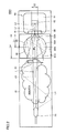
- FIG. 1 is a schematic cross-sectional view of a gas concentration measuring apparatus according to the present embodiment. With reference to FIG. 1, the gas concentration measuring apparatus according to the present embodiment will be described.
- a gas concentration measuring apparatus 100 includes a sample cell 10, a light source 20, a bandpass filter 41, a detector 60, and a waveguide forming member 90.
- the gas concentration measuring apparatus 100 measures the gas concentration according to the absorbance of the sample gas flowing between the light source 20 that emits infrared light and the detector 60 having the light receiving unit 62 that receives infrared light.
- the sample cell 10 has a sample gas circulation space inside and is provided so that the sample gas can be circulated.
- a sample gas introduction hole (not shown) is connected to one end side (light source 20 side) of the sample cell 10
- a sample gas outlet hole (not shown) is connected to the other end side (detector 60 side) of the sample cell 10.
- the sample gas led out to the sample cell 10 through the sample gas introduction hole is discharged from the sample gas lead-out hole.
- the sample cell 10 accommodates the light source 20, the waveguide forming member 90, the band pass filter 41, and the detector 60 therein.
- the light source 20, the waveguide forming member 90, the band pass filter 41, and the detector 60 are arranged in this order from one end side (left side in the figure) of the sample cell 10, for example.
- the light source 20 emits infrared rays.
- a filament lamp or an LED lamp that emits broadband infrared light including desired infrared light can be employed. Part of the infrared light emitted from the light source 20 is absorbed based on the infrared absorption wavelength characteristics of the sample gas.
- the sample gas is, for example, carbon dioxide, and its absorption band is about 4.3 ⁇ m.
- the waveguide forming member 90 includes a waveguide portion 93 having a cylindrical inner peripheral surface shape, an inlet portion 91 that is formed on one side of the waveguide portion 93 and introduces infrared rays from the light source 20, and the waveguide portion 93. It includes an exit portion 92 that is formed on the other side and guides infrared rays that have passed through the waveguide portion 93 toward the detector 60 side.
- the waveguide forming member 90 guides infrared rays partially absorbed by the sample gas toward the detector 60.
- the inner peripheral surface of the waveguide portion 93 is provided with a tapered region whose cross-sectional area decreases from the inlet portion 91 toward the outlet portion 92.
- the tapered region includes a frustum shape whose peripheral length becomes shorter from the inlet portion 91 toward the outlet portion 92.
- the frustum shape means a frustum shape and a polygonal frustum shape.
- a resin material such as ABS resin (acrylonitrile butadiene styrene copolymer synthetic resin) or PC resin (polycarbonate resin) can be employed.
- ABS resin acrylonitrile butadiene styrene copolymer synthetic resin
- PC resin polycarbonate resin
- the band pass filter 41 is provided on one end side of the detector 60 located on the waveguide forming member 90 side.
- the bandpass filter 41 is fixed in a state of being fitted in a recess 64 provided on the surface of the detector 60 facing the waveguide forming member 90.
- the band-pass filter 41 is configured to transmit infrared rays in the absorption band of the sample gas to be detected. Thereby, only infrared rays having a desired wavelength band reach the detector 60.
- an infrared detector such as a thermopile or a bolometer can be employed.
- the detector 60 includes a main body portion 61, a light receiving portion 62, and a concave portion 64.
- a light receiving unit 62 is embedded in the main body 61.
- the light receiving unit 62 receives infrared rays derived from the exit portion 92 of the waveguide forming member 90 via the bandpass filter 41.
- the detector 60 is electrically connected to a signal processing circuit board (not shown). Based on the infrared light received by the light receiving unit 62, the detector 60 outputs an output signal to the signal processing circuit board.
- the signal processing circuit board calculates the concentration of the sample gas based on the output signal.
- the transmission band of the bandpass filter 41 shifts to the short wavelength side as the incident angle increases. As the transmission band is changed in this way, the measurement accuracy is lowered. Therefore, it is preferable that the incident angle of the infrared ray incident on the bandpass filter 41 is small in the measurement.
- the waveguide forming member 90 is for suppressing the influence on the measurement accuracy given by infrared rays having a large incident angle incident on the bandpass filter 41 located at the transmission position.
- An infrared ray (for example, arrow L in FIG. 1) that travels straight in a range that is a logical sum of a region surrounded by the outermost line of infrared L1 and a region surrounded by the outermost line of infrared L2 is a bandpass filter. It passes through 41 and reaches the light receiving unit 62.
- the infrared ray L1 is light having a frustum shape that goes straight to the detector 60 side along the peripheral surface of the waveguide section 93.
- the infrared ray L2 is formed, for example, when light that travels straight from the lower end of the entrance portion 91 of the waveguide forming member 90 toward the upper end of the light receiving portion 62 is rotated once along the opening shape of the entrance portion 91. It is light including two truncated cone shapes.
- the infrared rays L4 and L5 enter the waveguide portion 93 from the entrance portion 91 at a relatively large angle with respect to the axial direction of the waveguide portion 93. Infrared rays L4 and L5 travel toward the detector 60 while being reflected by the inner peripheral surface of the waveguide section 93 a plurality of times.
- the infrared rays L4 and L5 may be incident on the bandpass filter 41 with a large incident angle.
- the waveguide forming member 90 is formed of a resin member having a reflectance of 20% or less, the infrared rays L4 and L5 are repeatedly reflected in the waveguide portion 93. Thus, absorption is attenuated. For example, when a member having a reflectivity of 10% is used, the infrared ray is reflected five times, thereby having the same attenuation effect as that when the member is reflected once by a member having a reflectivity of 0.001%.
- the opening area S1 of the inlet 91 of the waveguide forming member 90 is larger than the opening area S2 of the outlet 92 and providing a tapered region in the waveguide 93, the number of reflections of the infrared rays L4 and L5 is increased. be able to.
- the waveguide forming member 90 multiplies the infrared rays that have entered the waveguide portion 93 from the entrance portion 91 into the tapered region, thereby converting the energy of the infrared rays incident on the bandpass filter 41 in an oblique direction. Attenuate. Thereby, the measurement accuracy of the gas concentration measuring apparatus can be improved.
- the provision of the waveguide forming member 90 can attenuate infrared energy incident in an oblique direction.
- the measurement accuracy of the apparatus 100 can be improved.
- the sample gas is carbon dioxide, but is not limited thereto.
- a gas such as carbon monoxide, CH 4 or NOx may be used.
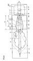
- FIG. 2 is a schematic cross-sectional view of the gas concentration measuring apparatus according to the present embodiment. With reference to FIG. 2, a gas concentration measuring apparatus 100A according to the present embodiment will be described.
- the gas concentration measuring device 100A according to the present embodiment has a waveguide portion 93A having a shape of the waveguide forming member 90A when compared with the gas concentration measuring device 100 according to the first embodiment. Is different. Other configurations are almost the same.
- the opening area S1 of the inlet portion 91A is larger than the opening area S2 of the outlet portion 92A.
- the internal shape of the waveguide section 93A includes a part of a spherical shape. A portion of the inner peripheral surface of the waveguide portion 93A that constitutes a part of the spherical surface is provided between the inlet portion 91A and the outlet portion 92A.
- the portion constituting a part of the spherical surface has a first spherical surface portion 95 directed toward the outlet portion 92A and a second spherical surface portion 96 directed toward the inlet portion 91A with the central portion M of the sphere as a boundary.
- the portion from the first spherical surface portion 95 to the outlet portion 92A corresponds to a tapered region whose sectional area decreases from the inlet portion 91A side to the outlet portion 92A side, and from the inlet portion 91A side to the outlet portion 92A side. It corresponds to the first curved shape portion whose circumference becomes shorter as it goes.
- the second spherical surface portion 96 corresponds to a second curved shape portion whose circumferential length becomes shorter from the outlet portion 92A side toward the inlet portion 91A side.
- the range of the logical sum of the region surrounded mainly by the outermost line of the infrared ray L1 and the region surrounded by the outermost line of the infrared ray L2 is within the range.
- Infrared rays traveling in a straight line reach the light receiving unit 62.
- the infrared ray L1 is light having a frustum shape that goes straight to the detector 60 side along the peripheral surfaces of the inlet portion 91A and the outlet portion 92A.
- Infrared ray L2 is the same light as in the first embodiment.
- Infrared rays L4 and L5 that have entered the waveguide portion 93A from the entrance portion 91A at a relatively large angle with respect to the axial direction of the waveguide portion 93A are transmitted a plurality of times at the first spherical portion 95 and the second spherical portion 96. It is reflected and emitted from the entrance 91A.
- the infrared rays L4 and L5 emitted from the entrance 91A are not incident on the bandpass filter 41.
- the length Lb of the portion from the first spherical portion 95 to the exit portion 92A in the axial direction of the waveguide portion 93A is the length of the waveguide forming member 90. It is preferably at least half of La.
- the present embodiment it is possible to attenuate the infrared energy incident in the oblique direction with respect to the bandpass filter 41, and to emit a part of the infrared light incident in the oblique direction from the inlet portion 91A. be able to. Thereby, the measurement accuracy of the gas concentration measuring apparatus 100A can be further improved.
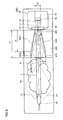
- FIG. 3 is a schematic cross-sectional view of the gas concentration measuring apparatus according to the present embodiment. With reference to FIG. 3, the gas concentration measuring apparatus 100B according to the present embodiment will be described.
- the gas concentration measuring device 100B according to the present embodiment has a waveguide portion 93B of the waveguide forming member 90B having a shape that is different from that of the gas concentration measuring device 100 according to the first embodiment. Is different. Other configurations are almost the same.
- the opening area S1 of the inlet portion 91B is larger than the opening area S2 of the outlet portion 92B.
- the internal shape of the waveguide portion 93B includes a first curved shape portion 93B1 and a second curved shape portion 93B2.
- the waveguide portion 93B includes a maximum circumferential length portion 94B. The maximum circumferential length portion 94B is provided between the inlet portion 91B and the outlet portion 92B.
- the first curved shape portion 93B1 is an internal shape of the waveguide portion 93B from the maximum peripheral length portion 94B to the outlet portion 92B.
- the first curved shape portion 93B1 is provided so that the circumferential length becomes shorter from the inlet portion 91B side toward the outlet portion 92B.
- the second curved shape portion 93B2 is an internal shape of the waveguide portion 93B from the maximum circumferential length portion 94B to the inlet portion 91B.
- the second curved shape portion 93B2 is provided so that the circumferential length becomes shorter from the outlet portion 92B side toward the inlet portion 91B.
- the infrared ray that travels straight in the range that is the logical sum of the region surrounded by the outermost line of the infrared ray L1 and the region surrounded by the outermost line of the infrared ray L2 reaches the light receiving unit 62.
- the infrared ray L1 is light having a frustum shape that goes straight to the detector 60 side along the periphery of the inlet portion 91B and the outlet portion 92B.
- Infrared ray L2 is the same light as in the first embodiment.
- the length Lb of the first curved portion 93B1 in the axial direction of the waveguide forming member 90B is preferably at least half the length La of the waveguide forming member 90B in the axial direction.
- FIG. 4 is a schematic cross-sectional view of the gas concentration measuring apparatus according to the present embodiment. With reference to FIG. 4, a gas concentration measuring apparatus 100C according to the present embodiment will be described.
- the gas concentration measuring apparatus 100C according to the present embodiment has a waveguide portion 93C having a shape of the waveguide forming member 90C when compared with the gas concentration measuring apparatus 100 according to the first embodiment. Is different. Other configurations are almost the same.
- the opening area S1 of the inlet portion 91C is larger than the opening area S2 of the outlet portion 92C.
- the internal shape of the waveguide 93C includes a first frustum-shaped portion 93C1 and a second frustum-shaped portion 93C2.
- the waveguide portion 93C includes a maximum circumferential length portion 94C. The maximum circumferential length portion 94C is provided between the inlet portion 91C and the outlet portion 92C.
- the first frustum-shaped portion 93C1 is the internal shape of the waveguide portion 93C from the maximum circumferential length portion 94C to the outlet portion 92C.
- the first frustum-shaped portion 93C1 is provided so that the circumferential length decreases from the inlet portion 91C side toward the outlet portion 92C.
- the second frustum-shaped portion 93C2 is the internal shape of the waveguide portion 93C from the maximum circumferential length portion 94C to the inlet portion 91C.
- the second frustum-shaped portion 93C2 is provided such that the circumferential length decreases from the outlet portion 92C side toward the inlet portion 91C.
- the infrared ray that travels straight in the range that is the logical sum of the region surrounded by the outermost line of the infrared ray L1 and the region surrounded by the outermost line of the infrared ray L2 reaches the light receiving unit 62.
- the infrared ray L1 is light having a frustum shape that goes straight to the detector 60 side along the periphery of the inlet portion 91C and the outlet portion 92C.
- Infrared ray L2 is the same light as in the first embodiment.
- the length Lb of the first frustum-shaped portion 93C1 in the axial direction of the waveguide forming member 90C is preferably not less than half the length La of the waveguide forming member 90C in the axial direction.
- the gas concentration measuring apparatus 100C it is possible to reliably attenuate the energy of infrared rays incident on the band-pass filter 41 in an oblique direction. As a result, the measurement accuracy of the gas concentration measuring device can be improved.
- FIG. 5 is a schematic cross-sectional view of the gas concentration measuring apparatus according to the present embodiment. With reference to FIG. 5, a gas concentration measurement apparatus 100D according to the present embodiment will be described.
- the gas concentration measuring apparatus 100D according to the present embodiment has a waveguide portion 93D of the waveguide forming member 90D having a shape that is different from that of the gas concentration measuring apparatus 100C according to the fourth embodiment. Is different.
- the opening area S1 of the inlet portion 91D is larger than the opening area S2 of the outlet portion 92D.
- the internal shape of the waveguide portion 93D includes a frustum-shaped portion 93D1 and a columnar shape portion 93D2.
- the frustum-shaped portion 93D1 has substantially the same shape as the first frustum-shaped portion 93C1 according to the fourth embodiment.
- the length relationship between the frustum-shaped portion 93D1 and the waveguide forming member 90D is the same as the relationship between the first frustum-shaped portion 93C1 and the waveguide forming member 90C according to the fourth embodiment.
- the columnar shape portion 93D2 is provided so that the circumferential length is constant from the inlet portion 91D to the end of the frustum-shaped portion 93D1 located on the upstream side.
- the circumferential length of the columnar portion 93D2 is provided to be the maximum.
- the infrared rays L4 and L5 entering from the entrance portion 91D with a relatively large angle with respect to the axial direction of the waveguide portion 93D are transmitted through the frustum-shaped portion 93D1 and the columnar shape portion. It can be reflected multiple times within 93D2.
- the energy of infrared rays incident on the bandpass filter 41 in an oblique direction can be surely attenuated.
- the measurement accuracy of the gas concentration measuring device can be improved.
- the case where the columnar shape portion is provided on the inlet portion 91D side and the frustum-shaped portion is provided on the outlet portion 92D side has been described as an example.
- the body-shaped part may be provided on the outlet part 92D side, and the frustum-shaped part may be provided on the inlet part 91D side.
- the peripheral length of the columnar shape portion is provided to be minimized.
- the portion connecting the inlet 91A and the end of the second spherical portion 96 on the upstream side (first connecting portion), and the end of the first spherical portion 95 on the downstream side Although the case where the portion (second connecting portion) that connects the outlet portion 92A is provided so as to have a shorter circumference as it goes from the inlet portion 91A side to the outlet portion 92A side has been described, it is limited to this. Instead, at least one of the first connection portion and the second connection portion may be provided in a columnar shape having a constant circumference.
- the present invention is not limited to this, and instead of the second curved shape portion 93B2.
- the columnar shape portion may be provided so that the peripheral length is constant from the inlet portion 91B to the maximum peripheral length portion 94B.
Landscapes
- Chemical & Material Sciences (AREA)
- Physics & Mathematics (AREA)
- Health & Medical Sciences (AREA)
- Life Sciences & Earth Sciences (AREA)
- Immunology (AREA)
- Biochemistry (AREA)
- General Health & Medical Sciences (AREA)
- General Physics & Mathematics (AREA)
- Analytical Chemistry (AREA)
- Pathology (AREA)
- Engineering & Computer Science (AREA)
- Spectroscopy & Molecular Physics (AREA)
- Combustion & Propulsion (AREA)
- Food Science & Technology (AREA)
- Medicinal Chemistry (AREA)
- Investigating Or Analysing Materials By Optical Means (AREA)
Abstract
Priority Applications (3)
| Application Number | Priority Date | Filing Date | Title |
|---|---|---|---|
| JP2016531226A JP6245366B2 (ja) | 2014-07-03 | 2015-06-11 | ガス濃度測定装置 |
| EP15815028.4A EP3165905B1 (fr) | 2014-07-03 | 2015-06-11 | Dispositif de mesure de concentration de gaz |
| US15/384,362 US10254222B2 (en) | 2014-07-03 | 2016-12-20 | Gas concentration measurement device |
Applications Claiming Priority (2)
| Application Number | Priority Date | Filing Date | Title |
|---|---|---|---|
| JP2014-137787 | 2014-07-03 | ||
| JP2014137787 | 2014-07-03 |
Related Child Applications (1)
| Application Number | Title | Priority Date | Filing Date |
|---|---|---|---|
| US15/384,362 Continuation US10254222B2 (en) | 2014-07-03 | 2016-12-20 | Gas concentration measurement device |
Publications (1)
| Publication Number | Publication Date |
|---|---|
| WO2016002467A1 true WO2016002467A1 (fr) | 2016-01-07 |
Family
ID=55019016
Family Applications (1)
| Application Number | Title | Priority Date | Filing Date |
|---|---|---|---|
| PCT/JP2015/066873 Ceased WO2016002467A1 (fr) | 2014-07-03 | 2015-06-11 | Dispositif de mesure de concentration de gaz |
Country Status (4)
| Country | Link |
|---|---|
| US (1) | US10254222B2 (fr) |
| EP (1) | EP3165905B1 (fr) |
| JP (1) | JP6245366B2 (fr) |
| WO (1) | WO2016002467A1 (fr) |
Cited By (1)
| Publication number | Priority date | Publication date | Assignee | Title |
|---|---|---|---|---|
| US10161859B2 (en) | 2016-10-27 | 2018-12-25 | Honeywell International Inc. | Planar reflective ring |
Families Citing this family (1)
| Publication number | Priority date | Publication date | Assignee | Title |
|---|---|---|---|---|
| JP6556338B2 (ja) * | 2016-04-15 | 2019-08-07 | Phcホールディングス株式会社 | ガスセンサ及び恒温装置 |
Citations (3)
| Publication number | Priority date | Publication date | Assignee | Title |
|---|---|---|---|---|
| JP2004117259A (ja) * | 2002-09-27 | 2004-04-15 | Horiba Ltd | 車載型hc測定装置 |
| JP2007501404A (ja) * | 2003-05-13 | 2007-01-25 | ハイマン・センサー・ゲゼルシャフト・ミット・ベシュレンクテル・ハフツング | 最適化された表面を活用する赤外線センサー |
| JP2012202918A (ja) * | 2011-03-28 | 2012-10-22 | Horiba Stec Co Ltd | 分光光学計及びその校正方法 |
Family Cites Families (20)
| Publication number | Priority date | Publication date | Assignee | Title |
|---|---|---|---|---|
| US4011451A (en) * | 1975-07-03 | 1977-03-08 | Waters Associates, Incorporated | Novel photometric system |
| IE44010B1 (en) * | 1976-02-25 | 1981-07-29 | Rossiter V | Method and apparatus for examining the infrared spectrum of small quantities of materials in the vapour phase |
| US4084909A (en) * | 1976-07-19 | 1978-04-18 | International Business Machines Corporation | Drum monochromator |
| US4736103A (en) * | 1986-03-07 | 1988-04-05 | Westinghouse Electric Corp. | Spectrometer test gas chamber |
| JPH07236040A (ja) * | 1994-02-22 | 1995-09-05 | Nippon Avionics Co Ltd | カラー用ラインセンサカメラ |
| JPH10309281A (ja) * | 1997-05-13 | 1998-11-24 | Olympus Optical Co Ltd | 蛍光診断装置 |
| JP2004239611A (ja) | 1999-10-12 | 2004-08-26 | Nok Corp | Coセンサ |
| SE520664C2 (sv) * | 2000-04-27 | 2003-08-05 | Senseair Ab | Koldioxidanpassad gascell |
| JP3771849B2 (ja) * | 2001-09-27 | 2006-04-26 | 株式会社堀場製作所 | 赤外線ガス分析方法および装置 |
| JP2003215037A (ja) * | 2002-01-25 | 2003-07-30 | Horiba Ltd | Ndir法によるhc分析方法および装置 |
| US6865472B2 (en) | 2002-09-27 | 2005-03-08 | Horiba Ltd. | Vehicle-installed exhaust gas analyzing apparatus |
| JP4663258B2 (ja) * | 2003-06-17 | 2011-04-06 | オリンパス株式会社 | 内視鏡装置 |
| JP3991029B2 (ja) * | 2003-12-19 | 2007-10-17 | 株式会社日立ハイテクノロジーズ | 核酸分析装置 |
| KR100791961B1 (ko) * | 2004-12-24 | 2008-01-04 | 코리아디지탈 주식회사 | 비분산형 적외선 가스 측정장치의 도파로 구조 |
| JP2010223610A (ja) * | 2009-03-19 | 2010-10-07 | Toyota Central R&D Labs Inc | 自己形成光導波路型センサ |
| EP2444791B1 (fr) * | 2010-10-25 | 2020-04-15 | General Electric Company | Analyseur de gaz mesurant au moins deux composants d'un gaz |
| JP5870270B2 (ja) * | 2011-10-24 | 2016-02-24 | パナソニックIpマネジメント株式会社 | 検出器 |
| JP2013120153A (ja) * | 2011-12-08 | 2013-06-17 | Panasonic Corp | 気体成分検出装置 |
| JP6333257B2 (ja) * | 2012-08-30 | 2018-05-30 | アイティーアイ・スコットランド ‐ スコティッシュ・エンタープライズIti Scotland ‐ Scottish Enterprise | 長波長赤外線の検出および長波長赤外光源を用いた画像処理 |
| CN104797926B (zh) * | 2012-11-30 | 2017-12-26 | 松下知识产权经营株式会社 | 光学传感器设备以及在光学传感器设备中使用的光学元件的生产方法 |
-
2015
- 2015-06-11 WO PCT/JP2015/066873 patent/WO2016002467A1/fr not_active Ceased
- 2015-06-11 EP EP15815028.4A patent/EP3165905B1/fr active Active
- 2015-06-11 JP JP2016531226A patent/JP6245366B2/ja active Active
-
2016
- 2016-12-20 US US15/384,362 patent/US10254222B2/en active Active
Patent Citations (3)
| Publication number | Priority date | Publication date | Assignee | Title |
|---|---|---|---|---|
| JP2004117259A (ja) * | 2002-09-27 | 2004-04-15 | Horiba Ltd | 車載型hc測定装置 |
| JP2007501404A (ja) * | 2003-05-13 | 2007-01-25 | ハイマン・センサー・ゲゼルシャフト・ミット・ベシュレンクテル・ハフツング | 最適化された表面を活用する赤外線センサー |
| JP2012202918A (ja) * | 2011-03-28 | 2012-10-22 | Horiba Stec Co Ltd | 分光光学計及びその校正方法 |
Cited By (1)
| Publication number | Priority date | Publication date | Assignee | Title |
|---|---|---|---|---|
| US10161859B2 (en) | 2016-10-27 | 2018-12-25 | Honeywell International Inc. | Planar reflective ring |
Also Published As
| Publication number | Publication date |
|---|---|
| JPWO2016002467A1 (ja) | 2017-04-27 |
| US10254222B2 (en) | 2019-04-09 |
| EP3165905A4 (fr) | 2018-02-21 |
| JP6245366B2 (ja) | 2017-12-13 |
| EP3165905B1 (fr) | 2019-10-02 |
| US20170102328A1 (en) | 2017-04-13 |
| EP3165905A1 (fr) | 2017-05-10 |
Similar Documents
| Publication | Publication Date | Title |
|---|---|---|
| TWI513974B (zh) | 檢測器 | |
| CN110383043B (zh) | 光学气体传感器 | |
| JP2009541755A (ja) | 分光検出器、および液体中で血液や生体マーカー物質を判定する方法 | |
| US11747201B2 (en) | Infrared spectrophotometer | |
| CN105181602A (zh) | 一种基于光学积分球的光谱测量装置 | |
| EP2601512B1 (fr) | Dispositif optique annulaire | |
| US9915604B2 (en) | Gas concentration measurement device | |
| JP6245366B2 (ja) | ガス濃度測定装置 | |
| KR20180103760A (ko) | 침착물 센서를 구비한 광 센서 | |
| JP2015031682A (ja) | 蛍光検出器 | |
| JP2018084523A (ja) | ガス濃度測定装置 | |
| JP7291109B2 (ja) | 紙ウェブの測定装置及び方法 | |
| CN109754565B (zh) | 一种光电感烟烟雾探测暗室 | |
| KR102381817B1 (ko) | 복수의 타원 반사체를 포함하는 광 도파관 | |
| JPS59173734A (ja) | 赤外線ガス分析計 | |
| CN221750411U (zh) | 光检测装置及黄疸检测仪 | |
| CN109682772B (zh) | 非分光红外气体传感器 | |
| CN115015150A (zh) | 一种多通道冗余型高精度可燃气体浓度传感器 | |
| JP2010276427A (ja) | ガスセンサ | |
| JPS6011145A (ja) | 異物測定装置 | |
| CN108732120A (zh) | 用于红外探测器的信号增强的设备和方法 |
Legal Events
| Date | Code | Title | Description |
|---|---|---|---|
| 121 | Ep: the epo has been informed by wipo that ep was designated in this application |
Ref document number: 15815028 Country of ref document: EP Kind code of ref document: A1 |
|
| REEP | Request for entry into the european phase |
Ref document number: 2015815028 Country of ref document: EP |
|
| WWE | Wipo information: entry into national phase |
Ref document number: 2015815028 Country of ref document: EP |
|
| ENP | Entry into the national phase |
Ref document number: 2016531226 Country of ref document: JP Kind code of ref document: A |
|
| NENP | Non-entry into the national phase |
Ref country code: DE |