WO2016002736A1 - Dispositif de connexion transversale optique - Google Patents
Dispositif de connexion transversale optique Download PDFInfo
- Publication number
- WO2016002736A1 WO2016002736A1 PCT/JP2015/068741 JP2015068741W WO2016002736A1 WO 2016002736 A1 WO2016002736 A1 WO 2016002736A1 JP 2015068741 W JP2015068741 W JP 2015068741W WO 2016002736 A1 WO2016002736 A1 WO 2016002736A1
- Authority
- WO
- WIPO (PCT)
- Prior art keywords
- optical cross
- connect
- optical
- internal connection
- cross
- Prior art date
- Legal status (The legal status is an assumption and is not a legal conclusion. Google has not performed a legal analysis and makes no representation as to the accuracy of the status listed.)
- Ceased
Links
Images


Classifications
-
- H—ELECTRICITY
- H04—ELECTRIC COMMUNICATION TECHNIQUE
- H04J—MULTIPLEX COMMUNICATION
- H04J14/00—Optical multiplex systems
-
- H—ELECTRICITY
- H04—ELECTRIC COMMUNICATION TECHNIQUE
- H04B—TRANSMISSION
- H04B10/00—Transmission systems employing electromagnetic waves other than radio-waves, e.g. infrared, visible or ultraviolet light, or employing corpuscular radiation, e.g. quantum communication
- H04B10/27—Arrangements for networking
-
- H—ELECTRICITY
- H04—ELECTRIC COMMUNICATION TECHNIQUE
- H04J—MULTIPLEX COMMUNICATION
- H04J14/00—Optical multiplex systems
- H04J14/02—Wavelength-division multiplex systems
- H04J14/03—WDM arrangements
- H04J14/0307—Multiplexers; Demultiplexers
-
- H—ELECTRICITY
- H04—ELECTRIC COMMUNICATION TECHNIQUE
- H04Q—SELECTING
- H04Q3/00—Selecting arrangements
- H04Q3/42—Circuit arrangements for indirect selecting controlled by common circuits, e.g. register controller, marker
- H04Q3/52—Circuit arrangements for indirect selecting controlled by common circuits, e.g. register controller, marker using static devices in switching stages, e.g. electronic switching arrangements
Definitions
- the present invention relates to an optical cross-connect device provided in an optical network and capable of outputting input wavelength division multiplexed light from a desired output port in wavelength group units or wavelength units.
- WDM Wavelength Division Multiplexing
- the number of optical input fibers for example, m includes the number of optical fibers from a plurality of adjacent optical nodes
- the number of optical output fibers, for example, n indicates the number of optical fibers to a plurality of adjacent optical nodes. included.
- the optical cross-connect equipment that constitutes each optical node routes wavelength division multiplexed optical signals transmitted via optical fibers in units of wavelengths or in units of wavelength groups as optical signals. As a result, transmission with large capacity and low power consumption is realized. For example, this is the optical cross-connect device described in Patent Document 1.
- a wavelength selective switch (WSS) is used for its configuration, but the scale is limited to about 1 ⁇ 20 at the maximum, and a large optical cross-connect device is used. It was difficult to configure a connect device. That is, when the wavelength selective switch (WSS) used in the optical cross-connect device functions as a duplexer, for example, in a configuration using a MEMS mirror, the wavelength selective switch (WSS) starts from one of the end faces of a plurality of optical fibers.
- a diffraction grating that splits the output light a condenser lens that condenses the light split by the diffraction grating onto the same number of MEMS mirrors as the demultiplexing number, and the light that is selectively reflected by the MEMS mirror. Since a configuration is adopted in which a wavelength is selected from wavelength division multiplexed light by a three-dimensional spatial optical system in which the light is incident on one of end faces of a plurality of optical fibers through a condenser lens and a diffraction grating. Increasing the number of output ports is not only expensive, requiring high-precision processing, but also increases optical loss. The maximum number of cables is limited to about 20 if the price is not taken into consideration, and it is practically difficult to realize a large-scale optical cross-connect device.
- optical cross-connect device when the number of optical fibers connected to the optical cross-connect device (optical node) increases with the spread of distribution services such as high-definition video, the cost and Technically difficult to implement and could not be handled easily.
- the present invention has been made against the background of the above circumstances, and the object of the present invention is to have a path switching function in an optical node in an optical network and to have a significantly small hardware scale and an optical loss. It is to provide an optical cross-connect device with a small amount.
- the gist of the present invention is that (a) an optical network in which optical nodes are connected to each other via a plurality of inter-node optical fibers is arranged at the optical node. (B) an inter-node connection input port and an inter-node connection output port connected to the plurality of inter-node connection optical fibers, an internal connection input port, and an internal connection, respectively.
- optical cross-connect unit includes a plurality of inputs corresponding to the number of the inter-node connection input ports and the number of the internal connection input ports, and the inter-node connection output. In that it is arranged out of a single wavelength selective switch having a plurality output corresponding to the number of over bets and the internal connection output port.
- the thus configured optical cross-connect device of the present invention includes an inter-node connection input port and an inter-node connection output port respectively connected to a plurality of inter-node connection optical fibers, an internal connection input port, and A plurality of optical cross-connect units (subsystems) each having an internal connection output port are provided, and any of the plurality of optical cross-connect units has an internal connection output port of a predetermined optical cross-connect unit.
- optical cross-connect units subsystems
- any of the plurality of optical cross-connect units has an internal connection output port of a predetermined optical cross-connect unit.
- the plurality of optical cross-connect units include a plurality of inputs corresponding to the number of the inter-node connection input ports and the number of the internal connection input ports, an inter-node connection output port, and the internal connection output ports.
- Each unit is composed of a single wavelength selective switch with multiple outputs corresponding to the number, so the optical cross-connect part is greatly reduced in size and the optical coupler used in the conventional optical cross-connect is not required Therefore, the optical loss is preferably reduced.
- the single wavelength selective switch includes a plurality of light beams corresponding to the plurality of inputs and the plurality of outputs and arranged in such a manner that end faces are arranged in series.
- a fiber array having fibers, and wavelength-division multiplexed light input from any one of the plurality of optical fibers corresponding to the plurality of inputs for example, a reflective diffraction grating, a mirror,
- a spectral element such as a prism and any one of the plurality of optical fibers corresponding to the plurality of outputs by receiving a wavelength dispersed by the spectral element and controlling a reflection direction of the wavelength.
- a demultiplexer that is provided for each optical input fiber and demultiplexes wavelength division multiplexed light for each wavelength, and an optical path demultiplexed by the demultiplexer.
- 1 ⁇ n optical switches with several wavelengths that perform path switching for each wavelength each optical output fiber is provided with a wavelength that is switched by the 1 ⁇ n optical switch, and is combined and output to the optical output fiber.
- the number of elements is small and the scale is relatively small, and an optical coupler is used as the provisional demultiplexer or optical multiplexer. Therefore, the optical loss is greatly reduced.
- the single wavelength selective switch includes a plurality of optical fibers of one row or a plurality of rows corresponding to the plurality of inputs and the plurality of outputs, the end faces being arranged in series.
- a wavelength-division-multiplexed light input from any one of the plurality of optical fibers corresponding to the plurality of inputs, for example, a reflection type diffraction grating, a mirror, or
- a spectral element such as a prism and the wavelength dispersed by the spectral element and controlling the diffraction direction of the wavelength, to one of the plurality of optical fibers corresponding to the plurality of outputs
- a liquid crystal element LCOS Liquid Crystal on Silicon
- a demultiplexer that is provided for each optical input fiber and demultiplexes wavelength division multiplexed light for each wavelength, and an optical path demultiplexed by the demultiplexer.
- 1 ⁇ n optical switches with several wavelengths that perform path switching for each wavelength each optical output fiber is provided with a wavelength that is switched by the 1 ⁇ n optical switch, and is combined and output to the optical output fiber.
- the number of elements is small and the scale is relatively small, and an optical coupler is used as the provisional demultiplexer or optical multiplexer. Therefore, the optical loss is greatly reduced.
- an internal connection output port of a predetermined optical cross-connect unit is directly connected to an internal connection input port of another optical cross-connect unit.
- the internal connection output port of the other optical cross-connect unit is directly connected to the internal connection input port of the predetermined optical cross-connect unit.
- the optical cross-connect unit can be routed by detouring between the optical cross-connect units, so that the optical cross-connect unit or the optical cross-connect unit has the same capacity as the conventional optical cross-connect device with the same number of input / output fibers.
- the scale of hardware such as wavelength selective switches can be greatly reduced.
- an internal connection output port of a predetermined optical cross-connect unit is directly connected to an internal connection input port of another optical cross-connect unit. And indirectly connected to the internal connection input port of the other optical cross-connect unit via the other optical cross-connect unit, and the internal connection input port and the internal connection output port They are connected in a state of being connected in a ring via an internal connection optical fiber that connects them.
- the optical cross-connect device is composed of three or more optical cross-connect units (subsystems) and can be routed by detouring between the optical cross-connect units. Compared to the optical cross-connect device, the capacity of the hardware such as the optical cross-connect unit or the wavelength selective switch can be greatly reduced while having the same path capacity.
- an internal connection output port of a predetermined optical cross-connect unit is directly connected to an internal connection input port of another optical cross-connect unit.
- the output port for internal connection of the other optical cross-connect unit is directly connected to the input port for internal connection of the predetermined optical cross-connect unit, and the predetermined optical cross-connect unit and / or other light
- At least one of the cross-connect units includes an additional internal connection input port and an internal connection output port.
- the optical cross-connect part or wavelength selection has the same capacity as the conventional optical cross-connect equipment with the same number of input / output fibers.
- the scale of hardware such as switches can be greatly reduced.
- it is connected to the optical node by connecting the internal connection output port and internal connection input port of the expansion optical cross-connect part to the new expansion internal connection input port and internal connection output port, respectively.
- new optical cross-connect units can be easily and inexpensively added.
- an internal connection output port of a predetermined optical cross-connect unit among the plurality of optical cross-connect units is directly connected to an internal connection input port of another optical cross-connect unit, and It is indirectly connected to an internal connection input port of another optical cross-connect unit via the other optical cross-connect unit, and at least one of the plurality of optical cross-connect units is another An internal connection input port and an internal connection output port that are not connected to the optical cross-connect section and connect between the internal connection input port and the internal connection output port They are connected in a chain through a fiber.
- the optical cross-connect device is composed of three or more optical cross-connect units (subsystems) and can be routed by detouring between the optical cross-connect units.
- the scale of hardware such as an optical cross-connect unit or a wavelength selective switch can be greatly reduced while having the same path capacity.
- the optical fiber connected to the optical node by connecting the internal connection output port and internal connection input port of the expansion optical cross-connect part to the internal connection input port and internal connection output port for expansion.
- a new optical cross-connect unit can be added at low cost and easily in accordance with the increase in
- the number of the plurality of optical cross-connect units arranged in the optical cross-connect device is matched with the number of other nodes adjacent to the optical node in which the optical cross-connect device is arranged. You can also.
- the wavelength division multiplexed light includes wavelength channels having different signal bit rates, or includes wavelength channels having wavelengths having different wavelength intervals. In this way, the versatility of the optical cross-connect device is enhanced.
- FIG. 2 is a diagram illustrating a main part of a configuration example including a plurality of optical cross-connect units in which optical cross-connect devices corresponding to optical nodes are circularly connected in the optical network of FIG. 1. It is the schematic which shows that the optical cross-connect part which comprises the optical cross-connect apparatus of FIG. 2 is comprised from a single MxN wavelength selective switch. It is a figure explaining the structural example of the wavelength group selection switch used for the optical cross-connect apparatus of FIG. It is a figure explaining the other structural example of the wavelength group selection switch used for the optical cross-connect apparatus of FIG.
- the optical cross-connect device corresponding to the optical node in the optical network of FIG. 1 includes an extension internal connection input port and an internal connection output port in which a predetermined optical cross-connect unit is not connected to another optical cross-connect unit. It is a figure explaining the principal part of the structural example with which the some optical cross-connect part provided is connected in series. It is a figure explaining the principal part of the structural example in which the optical cross-connect apparatus of FIG. 8 consists of two optical cross-connect parts.
- FIG. 1 exemplifies a part of an optical network NW including a plurality of optical nodes ND0 to NDd and optical fibers connecting them.
- d is a positive integer indicating the number of optical nodes adjacent to the optical node ND0, and is 4 in this embodiment. Note that the number of fibers between adjacent nodes need not be constant. Since the optical nodes ND0 to ND4 are configured in the same manner, the optical node ND0 will be described below as a representative.
- the optical cross-connect device OXC arranged in the optical node ND0 includes the number of optical input fibers connected from other optical nodes ND0 to ND4 adjacent to the optical node ND0 or other optical nodes.
- the optical cross-connect device OXC includes the number of optical input fibers connected from other optical nodes ND0 to ND4 adjacent to the optical node ND0 or other optical nodes.
- four optical cross-connect parts (subsystem parts) OXC1 to OXC4 necessary for accommodating the number of optical fibers to be connected to are provided.
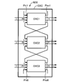
- FIG. 2 shows input / output connections of the optical cross-connect device OXC and internal connections between the optical cross-connect units OXC1 to OXC4 in the optical cross-connect device OXC.
- a total of M optical input fibers Fi1 to Fim, Fim + 1 to Fi2m, Fi2m + 1 to Fi3m from the optical nodes ND1 to NDd adjacent to the optical node ND0, Fi3m + 1 to Fi4m are connected.
- Fo3n and Fo3n + 1 to Fo4n are connected.
- Wavelength division multiplexed light is transmitted from the optical input fibers Fi1 to Fim, Fim + 1 to Fi2m, Fi2m + 1 to Fi3m, and Fi3m + 1 to Fi4m, respectively, and input to the optical cross-connect device OXC.
- the total number of the optical input fibers Fi1 to Fi4m is M
- the total number of the optical output fibers Fo1 to Fo4n is N.
- These optical input fibers Fi1 to Fi4m and the optical output fibers Fo1 to Fo4n are light for inter-node connection. It functions as a fiber.
- N M is often the case.
- the optical cross-connect device OXC performs path switching for each wavelength group or wavelength included in the wavelength division multiplexed light, and optical output fibers Fo1 to Fon, Fon + 1 to Fo2n, Fo2n + 1 to Fo3n. , Fo3n + 1 to Fo4n.
- a single wavelength division multiplexing is performed by combining a plurality of wavelength lights respectively corresponding to a plurality of wavelength channels (wave channels or light paths) arranged at a predetermined communication wavelength band, for example, 100 GHz.
- Wavelength Division Multiplexing light is configured, and the wavelength division multiplexed light is transmitted in parallel for each optical fiber.
- the wavelength division multiplexed light may be configured to include wavelength channels having different signal bit rates, or may be configured to include wavelength channels having wavelengths having different wavelength intervals.
- the four optical cross-connect units OXC1 to OXC4 are. Note that the number of optical cross-connect units need not match the number of adjacent optical nodes, and can be set independently of the number of adjacent nodes.
- These optical cross-connect units OXC1 to OXC4 are connected to the optical input fibers Fi1 to Fim, Fim + 1 to Fi2m, Fi2m + 1 to Fi3m, and Fi3m + 1 to Fi4m for external connection.
- Pi1 to Pim Connected to Pi1 to Pim, Pim + 1 to Pi2m, Pi2m + 1 to Pi3m, Pi3m + 1 to Pi4m and optical output fibers Fo1 to Fon, Fon + 1 to Fo2n, Fo2n + 1 to Fo3n, Fo3n + 1 to Fo4n, respectively
- the inter-node connection output ports Po1 to Pon, Pon + 1 to Po2n, Po2n + 1 to Po3n, and Po3n + 1 to Po4n are provided.
- optical cross-connect units OXC1 to OXC4 are for internal connection input ports Pni1 to Pni2, Pni3 to Pni4, Pni5 to Pni6, Pni7 to Pni8, and internal connection output ports Pno1 to Pno2, Pno3 to Pno4. , Pno5 to Pno6, and Pno7 to Pno8, respectively.
- the optical input fibers Fi1 to Fim from the optical node ND1 may be connected to the internode connection input ports Pi1 to Pim of the optical cross-connect unit OXC1, but a total of M from the optical nodes ND1 to ND4 Any m of these may be connected.
- optical output fibers Fo1 to Fon to the optical node ND1 may be connected to the internode connection output ports Po1 to Pon of the optical cross-connect unit OXC1, but the total N from the optical nodes ND1 to ND4 Any n of the books need only be connected.
- an internal connection output port of a predetermined optical cross-connect unit is an input port for internal connection of another optical cross-connect unit.
- an internal connection output port of a predetermined optical cross-connect unit is directly connected to an internal connection input port of another optical cross-connect unit, and further inside of another optical cross-connect unit The connection input port and the other optical cross-connect unit are indirectly connected.
- the internal connection input ports Pni1 and Pni2 of the optical cross-connect unit OXC1 are the internal connection output ports Pno8 of the other optical cross-connect units OXC4 and the internal connection output of the optical cross-connect unit OXC2. It is directly connected to the port Pno3 via the internal connection optical fibers Fn8 and Fn3, and further to the internal connection input ports Pni5 and Pni6 of the other optical cross-connect unit OXC3 and other optical cross-connect units OXC2 and internal connection It is indirectly connected through the optical fiber Fn4 and through the optical cross-connect unit OXC4 and the internal connection optical fiber Fn7.
- the optical cross-connect device OXC when the optical cross-connect device OXC includes three or more optical cross-connect units by the above connection method, they are interconnected so as to form a ring shape.
- the four optical cross-connect units OXC1 to OXC4 of this embodiment are interconnected in a ring shape.
- the output port for internal connection of one optical cross-connect unit is connected to the inside of the other optical cross-connect unit.
- the output port for internal connection of the other optical cross-connect unit is connected to the input port for internal connection of one optical cross-connect unit.
- the internal connection output port Pno2 of one optical cross-connect unit OXC1 is used for internal connection to the internal connection input port Pni3 of the other optical cross-connect unit OXC2.
- the internal connection output port Pno3 of the other optical cross-connect unit OXC2 is connected to the internal connection input port Pni2 of one optical cross-connect unit OXC1 via the internal connection optical fiber Fn3. It is connected.
- the internal connection output port Pno4 of one optical cross-connect unit OXC2 is used for internal connection to the internal connection input port Pni5 of the other optical cross-connect unit OXC3.
- the internal connection output port Pno5 of the other optical cross-connect unit OXC3 is connected to the internal connection input port Pni4 of one optical cross-connect unit OXC2 via the internal connection optical fiber Fn5. It is connected.
- the internal connection output port Pno6 of one optical cross-connect unit OXC3 is for internal connection to the internal connection input port Pni7 of the other optical cross-connect unit OXC4.
- the internal connection output port Pno7 of the other optical cross-connect unit OXC4 is connected to the internal connection input port Pni6 of one optical cross-connect unit OXC3 via the internal connection optical fiber Fn7. It is connected.
- the internal connection output port Pno8 of one optical cross-connect unit OXC4 is used for internal connection to the internal connection input port Pni1 of the other optical cross-connect unit OXC1.
- the internal connection output port Pno1 of the other optical cross-connect unit OXC1 is connected to the internal connection input port Pni8 of one optical cross-connect unit OXC4 via the internal connection optical fiber Fn1. It is connected.
- the optical cross-connect units OXC1 to OXC4 are among the optical cross-connect units OXC1 to OXC4. Since the wavelength output from the predetermined optical cross-connect section can be input to any other optical cross-connect section, the optical input fibers Fi1 to Fim, Fim + 1 to Fi2m, Fi2m + 1 to Fi3m , Fi3m + 1 to Fi4m can be switched to any one of the optical output fibers Fo1 to Fon, Fon + 1 to Fo2n, Fo2n + 1 to Fo3n, and Fo3n + 1 to Fo4n.
- the optical cross The predetermined wavelength is selected in the connection unit OXC1 and is output from the internal connection output port Pno2 to the internal connection input port Pni3 of the optical cross-connect unit OXC2.
- the predetermined wavelength is selected and output from the internal connection output port Pno4 to the internal connection input port Pni5 of the optical cross-connect unit OXC3.
- the predetermined wavelength is selected in the optical cross-connect unit OXC3 and output from the inter-node connection output port Po3n to the optical output fiber Fo3n.
- output is performed from any of the optical cross-connect units OXC1 to OXC4.
- an add signal transmitted at a predetermined wavelength from the router in the electrical layer is transmitted to the desired light directed by the add signal among the 4n optical output fibers Fo1 to Fo4n.
- Add wavelength selective switch WSS for sending out to wavelength division multiplexed light in the output fiber and a desired wavelength drop signal contained in the wavelength division multiplexed light from 4m optical input fibers Fin1 to Fi4m in the electrical layer A drop wavelength selective switch WSS for dropping to the router is provided as necessary.
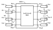
- the optical cross-connect unit OXC1 includes a single (m + 2) ⁇ (n + 2) wavelength selective switch WSS.
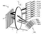
- the wavelength selective switch WSS includes, for example, a three-dimensional MEMS (Micro Electro Mechanical Systems) optical switch shown in FIG. 4 or an LCOS (Liquid Crystal on Silicon) switch shown in FIG.
- the wavelength selective switch WSS of FIG. 4 includes, for example, 4 ⁇ optical input fibers Fin1 to Fin4 and optical output fibers Fout1 to Fout4 whose end faces are connected in series, and four optical output fibers Fout1 to Fout4.
- This three-dimensional MEMS optical switch is controlled in posture by a reflective diffraction grating G, which is a spectral element that splits wavelength division multiplexed light input from any one of the optical input fibers Fin1 to Fin4 in units of wavelengths, and an actuator (not shown).
- a three-dimensional MEMS mirror 3DM comprising microfiber arrays MMA1 to MMA4 of several fibers (four sets in FIG.
- the light After being divided into wavelength units or wavelength group units by the spectroscopic grating G, the light is condensed on a predetermined micromirror MM for each wavelength by the condenser lens L.
- the wavelength selection switch function can be obtained by driving the micromirror MM so that the reflected light from the micromirror MM enters a desired one of the optical output fibers Fout1 to Fout4.
- micromirror arrays MMA1 to MMA4 are formed on one silicon substrate or glass substrate by a well-known three-dimensional MEMS technology, and the amplitude thereof is controlled by an actuator using static electricity, electrostrictive force or electromagnetic force, for example. It has come to be.
- the principle of the wavelength selective switch WSS of FIG. 5 is explained using, for example, a 4 ⁇ 4 scale LCOS optical switch having four optical input fibers Fin1 to Fin4 and four optical output fibers Fout1 to Fout4.
- the LCOS optical switch is a reflection type that is a spectroscopic element that splits wavelength-division multiplexed light input from any one of optical input fibers Fin1 to Fin4 through a polarizing element P, a condensing lens L1, and a mirror M in units of wavelengths.
- a large number of pixels having a diffraction grating G and a nematic liquid crystal layer aligned in parallel are arranged, and phase modulation is performed by modulating input light in accordance with a control signal.
- an integrated liquid crystal plate (reflective element) LCOS having four (four in FIG. 5) pixel regions A1 to A4 in the y direction, and is input from any one of the optical input fibers Fin1 to Fin4
- a predetermined pixel for each wavelength is obtained through the compensation plate C and the condenser lens L2.
- Phase modulation is performed by the pixels of the integrated liquid crystal element LCOS so that the reflected light from the integrated liquid crystal element LCOS is incident on a desired optical fiber among the optical output fibers Fout1 to Fout4.
- a wavelength selective switch function can be obtained.
- the integrated liquid crystal element LCOS is composed of, for example, a high-precision thin reflection type liquid crystal panel having a structure in which liquid crystal is confined between a silicon substrate having a liquid crystal driving circuit and pixel electrodes and an opposing transparent substrate.
- a plurality of optical input fibers (inter-node connection optical fibers) Fi1 to Fi4m and optical output fibers (inter-node connection optical fibers) Fo1 to Fo4n are connected to the inter-node connection input ports Pi1 to Pim, Pim + 1 to Pi2m, Pi2m + 1 to Pi3m, Pi3m + 1 to Pi4m, and the inter-node connection output ports Po1 to Pon, Pon + 1 to Po2n, respectively.
- Output port is directly connected to the internal connection input port of the other optical cross-connect section, and indirectly connected to the internal connection input port of the other optical cross-connect section via the other optical cross-connect section. Connected. Therefore, since the plurality of optical cross-connect units OXC1 to OXC4 can be detoured and routed, a conventional optical cross-connect device that does not have a plurality of interconnected optical cross-connect units with the same number of input / output fibers Compared to the above, it is possible to significantly reduce the scale of hardware such as the optical cross-connect unit or the wavelength selective switch WSS while having the same path capacity.
- the plurality of optical cross-connect units OXC1 to OXC4 are provided with a plurality of inputs (m + 2) corresponding to the number of inter-node connection input ports and the number of internal connection input ports, and for inter-node connection. Since each of the output ports and the plurality of outputs (n + 2) corresponding to the number of the internal connection output ports is composed of a single (m + 2) ⁇ (n + 2) wavelength selective switch WSS, the optical cross-connect units OXC1 ⁇ Since the OXC 4 is significantly reduced in size and an optical coupler is not required, the optical loss is also greatly reduced.
- the single wavelength selective switch WSS includes a plurality of optical fibers Fin1 to Fin4 and Fout1 arranged in such a manner that the end faces are in series corresponding to a plurality of inputs and the plurality of outputs.
- a reflection type diffraction grating G that divides the light every time, and the reflection direction of the wavelength is controlled by receiving the wavelength dispersed by the spectral element, thereby a plurality of optical fibers Fin1 to Fin4 and Fout1 to Fout4.
- 3D MEM having a plurality of micromirror arrays MMA1 to MMA4 that are selectively input to any one of optical fibers Fout1 to Fout4 corresponding to a plurality of outputs And (Micro Electro Mechanical Systems) mirror 3DM, is intended to include. Therefore, a demultiplexer that is provided for each optical input fiber and demultiplexes wavelength division multiplexed light for each wavelength, and several wavelengths for switching the path of the optical path demultiplexed by the demultiplexer for each wavelength.
- 1 ⁇ n optical switch provided for each optical output fiber, composed of a 1 ⁇ n multiplexer that receives the wavelength switched by the 1 ⁇ n optical switch and multiplexes and outputs to the optical output fiber
- the optical cross-connect unit not only the number of elements is relatively small, but also the scale is relatively small, and an optical coupler is not used as the provisional demultiplexer or optical multiplexer, so that optical loss is greatly increased. Reduced.
- the single wavelength selective switch WSS includes a plurality of optical fibers Fin1 to Fin4 and Fout1 arranged in such a manner that the end faces are in series corresponding to a plurality of inputs and the plurality of outputs.
- a reflection type diffraction grating G that spectrally separates each time, and the reflection (diffraction) direction of the wavelength is controlled by receiving the wavelength spectrally divided by the spectral element, so that the optical fibers Fout1 to Fout1- And an integrated liquid crystal element LCOS (Liquid Crystal on Silicon) having a plurality of reflective pixels to be selectively input to any one of Fout4.
- LCOS Liquid Crystal on Silicon
- a demultiplexer that is provided for each optical input fiber and demultiplexes wavelength division multiplexed light for each wavelength, and several wavelengths for switching the path of the optical path demultiplexed by the demultiplexer for each wavelength.
- 1 ⁇ n optical switch provided for each optical output fiber, composed of a 1 ⁇ n multiplexer that receives the wavelength switched by the 1 ⁇ n optical switch and multiplexes and outputs to the optical output fiber
- the optical cross-connect unit not only the number of elements is relatively small, but also the scale is relatively small, and an optical coupler is not used as the provisional demultiplexer or optical multiplexer, so that optical loss is greatly increased. Reduced.
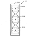
- the optical cross-connect device OXC in FIG. 2 is composed of four optical cross-connect units OXC1 to OXC4. However, as shown in FIG. 6, the optical cross-connect device OXC has the same input as the embodiment in FIG. Similarly, it can include three optical cross-connect units OXC1 to OXC3 which are provided with an output port and are externally connected and interconnected.
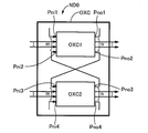
- the optical cross-connect device OXC of FIG. 2 is composed of four optical cross-connect units OXC1 to OXC4. However, as shown in FIG. 7, the optical cross-connect device OXC is the same as the embodiment of FIG. The optical cross-connect units OXC1 to OXC2 having the same input / output ports and similarly externally connected and interconnected.
- the output port Pno2 for internal connection of one (predetermined) optical cross-connect unit OXC1 is directly connected to the input port Pni3 for internal connection of the other optical cross-connect unit OXC2, and the other optical cross-connect unit
- the internal connection output port Pno3 of the OXC2 is directly connected to the internal connection input port Pni2 of the predetermined optical cross-connect unit OXC1.
- FIG. 8 shows an optical cross-connect device OXC according to another embodiment of the present invention.
- an optical fiber for internal connection that internally connects between the optical cross-connect unit OXC1 and the optical cross-connect unit OXC4 Fn1 and Fn8 are not provided, and the connection between the internal connection output port Pno1 and the internal connection input port Pni8 and the connection between the internal connection output port Pno8 and the internal connection input port Pni1 are open.
- the internal connection input port Pni1 and the internal connection output port Pno8, and the internal connection output port Pno1 and the internal connection input port Pni8 are the internal connection input port for expansion and the output port for internal connection for expansion. It is functioning.
- Other configurations are the same as those of the optical cross-connect device OXC in FIG.
- the optical cross-connect units OXC1 to OXC4 which are subsystems constituting the optical cross-connect device OXC of FIG. 8 are internally connected in series.
- the optical cross-connect device OXC1 is composed of three or more optical cross-connect units OXC1 to OXC4, and any of the three or more optical cross-connect units OXC1 to OXC4 has a predetermined optical cross-connect unit.
- the internal connection output ports are directly connected to the internal connection input ports of the other optical cross-connect units and connected in series via the internal connection optical fibers. For this reason, the wavelength output from the internal connection output port of the predetermined optical cross-connect unit is bidirectionally transmitted to a pair of adjacent optical cross-connect units among the optical cross-connect units connected in series. can do. For this reason, according to the optical cross-connect device OXC in FIG.
- routing can be performed between the plurality of optical cross-connect units OXC1 to OXC4.
- hardware such as an optical cross-connect unit or its wavelength selective switch WSS has the same capacity for accommodating a path. Can be greatly reduced.
- the plurality of optical cross-connect units OXC1 to OXC4 include inter-node connection input ports and the internal A single (m + 2) ⁇ () having a plurality of inputs (m + 2) corresponding to the number of connection input ports and a plurality of outputs (n + 2) corresponding to the number of inter-node connection output ports and the number of internal connection output ports. Since each of the n + 2) wavelength selective switches WSS is configured, the optical cross-connect units OXC1 to OXC4 are significantly reduced in size and an optical coupler is not required, so that the optical loss is also greatly reduced.
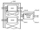
- the internal connection input port Pni11 for expansion that is not connected to the plurality of optical cross-connect units OXC1 to OXC4 provided in the optical cross-connect device OXC The extension optical cross-connect unit (subsystem) OXCA having the internal connection output port Pno11 can be easily connected. Therefore, the internal connection input port Pni11 and the internal connection output port Pno11 for expansion of the additional optical cross-connect unit OXCA are added to the existing optical cross-connect unit, for example, the internal connection output port Pno8 and the internal connection input port of OXC4. By connecting Pni8, new optical cross-connect units can be added sequentially and inexpensively in accordance with the further increase in the number of optical fibers connected to the optical node ND0.
- the optical cross-connect device OXC in FIG. 8 is composed of four optical cross-connect units OXC1 to OXC4. However, as shown in FIG. 9, the optical cross-connect device OXC has the same input as the embodiment in FIG. Similarly, the optical cross-connect device OXC can be composed of two optical cross-connect units OXC1 to OXC2 that have an output port and are externally connected and interconnected as shown in FIG. It can be composed of two optical cross-connect units OXC1 to OXC3 that have the same input / output ports as in the embodiment and are similarly externally connected and interconnected.
- optical cross-connect unit OXC1 shown in FIG. 10 is provided with an extension internal connection input port Pni1 and an internal connection output port Pno1 that are not connected to any of the other optical cross-connect units OXC2 to OXC3.
- the optical cross-connect unit OXC3 is provided with an extension internal connection input port Pni6 and an internal connection output port Pno6 that are not connected to any of the other optical cross-connect units OXC1-2. Also in the optical cross-connect device OXC shown in FIG. 9 and FIG. 10, the same effect as the optical cross-connect device OXC shown in FIG.
- FIG. 11 shows an internal connection input port Pni9 and an internal connection output for expansion of the optical cross-connect unit OXC1 among the plurality of optical cross-connect units OXC1 to OXC4 constituting the optical cross-connect device OXC of FIGS.
- the port Pno9 is connected to the additional optical cross-connect unit (additional subsystem) OXCA.
- This extension optical cross-connect unit OXCA has substantially the same basic configuration in that it includes (m + 2) ⁇ (n + 2) wavelength selective switch WSS, similarly to optical cross-connect units OXC1 to OXC1 to 4 shown in FIG. ing.
- the extension optical cross-connect unit OXCA includes the internal connection input port Pni10 and the internal connection output port connected to the extension internal connection input port Pni9 and the internal connection output port Pno9 of the optical cross-connect unit OXC1, respectively.
- an internal connection input port Pni11 and an internal connection output port Pno11 for two-stage expansion that are not connected to any of the plurality of optical crossconnect units OXC1 to OXC1 provided in the optical crossconnect device OXC are further provided. I have.
- FIG. 12 shows an internal connection input port Pni6 and an internal connection output port Pno6 for expansion of the optical cross-connect unit OXC3 among the plurality of optical cross-connect units OXC1 to OXC3 constituting the optical cross-connect device OXC of FIG.
- the optical cross-connect unit for expansion (expansion subsystem) OXCA is connected.
- the optical cross-connect units OXC1 to OXC4 in the first embodiment (FIG. 2) and the fifth embodiment (FIG. 8) are interconnected bidirectionally as shown in FIGS. May be interconnected to each other.
- the internal connection optical fibers Fn1 to Fn8 among the internal connection optical fibers Fn1 to Fn8, the internal connection optical fibers Fn1, F3n, Fn5, Fn7 or the internal connection optical fibers Fn2, F4n, Fn6, Fn8 may be omitted.
- the wavelength output from one of the optical cross-connect units OXC1 to OXC4 can be input to any other optical cross-connect unit.
- the number of the internal connection optical fibers Fn1 to Fn8 is one, it may be composed of a plurality.
- the optical cross-connect units OXC1 to OXC4 are internally connected via the internal connection optical fibers Fn1 to Fn8. It may be connected via a waveguide or the like.
- the optical cross-connect device OXC is composed of the four optical cross-connect units OXC1 to OXC4. You may comprise from a connection part.
- Optical network Optical cross-connect devices
- OXC1 to OXC4 Optical cross-connect unit WSS: Wavelength selective switches Fi1 to Fim, Fim + 1 to Fi2m, Fi2m + 1 to Fi3m, Fi3m + 1 to Fi4m: Optical input fiber (node) Optical fiber) Fo1 to Fon, Fon + 1 to Fo2n, Fo2n + 1 to Fo3n, Fo3n + 1 to Fo4n: Optical output fibers (inter-node connection optical fibers) Pi1 to Pim, Pim + 1 to Pi2m, Pi2m + 1 to Pi3m, Pi3m + 1 to Pi4m: Inter-node connection input ports Po1 to Pon, Pon + 1 to Po2n, Po2n + 1 to Po3n, Po3n + 1 to Po4n: Output ports for connection between nodes Pni1 to Pni2, Pni3 to Pni4, Pni5 to Pni6, P
Landscapes
- Engineering & Computer Science (AREA)
- Computer Networks & Wireless Communication (AREA)
- Signal Processing (AREA)
- Computing Systems (AREA)
- Physics & Mathematics (AREA)
- Electromagnetism (AREA)
- Use Of Switch Circuits For Exchanges And Methods Of Control Of Multiplex Exchanges (AREA)
- Optical Communication System (AREA)
Abstract
L'invention concerne un dispositif de connexion transversale optique doté d'une fonction de commutation de trajet pour des noeuds optiques dans un réseau optique, et pourvu de matériel à très petite échelle. Par rapport à n'importe laquelle d'une pluralité d'unités de connexion transversale optique qui constituent un dispositif répartiteur optique (OXC), un port de sortie d'utilisation de connexion interne d'une unité de connexion transversale optique déterminée est directement connecté à un port d'entrée de connexion interne d'une autre unité de connexion transversale optique ou un port de sortie d'utilisation de connexion interne d'une unité de connexion transversale optique déterminée est directement connecté à un port d'entrée d'utilisation de connexion interne d'une autre unité de connexion transversale optique et est indirectement connecté à un port d'entrée d'utilisation de connexion interne d'une autre unité de connexion transversale optique encore par l'intermédiaire de l'autre unité de connexion transversale optique. Ainsi, un routage de répétition peut être réalisé par établissement de circuits parmi la pluralité d'unités de connexion transversale optique, et l'échelle de matériel tel que les unités de connexion transversale optique ou les commutateurs de sélection de longueur d'onde (WSS) de celles-ci peut être considérablement réduite.
Applications Claiming Priority (2)
| Application Number | Priority Date | Filing Date | Title |
|---|---|---|---|
| JP2014135181A JP2017152749A (ja) | 2014-06-30 | 2014-06-30 | 光クロスコネクト装置 |
| JP2014-135181 | 2014-06-30 |
Publications (1)
| Publication Number | Publication Date |
|---|---|
| WO2016002736A1 true WO2016002736A1 (fr) | 2016-01-07 |
Family
ID=55019268
Family Applications (1)
| Application Number | Title | Priority Date | Filing Date |
|---|---|---|---|
| PCT/JP2015/068741 Ceased WO2016002736A1 (fr) | 2014-06-30 | 2015-06-29 | Dispositif de connexion transversale optique |
Country Status (2)
| Country | Link |
|---|---|
| JP (1) | JP2017152749A (fr) |
| WO (1) | WO2016002736A1 (fr) |
Families Citing this family (1)
| Publication number | Priority date | Publication date | Assignee | Title |
|---|---|---|---|---|
| WO2022091387A1 (fr) * | 2020-10-30 | 2022-05-05 | 日本電信電話株式会社 | Dispositif, système et procédé de communication optique |
Citations (4)
| Publication number | Priority date | Publication date | Assignee | Title |
|---|---|---|---|---|
| JP2006140598A (ja) * | 2004-11-10 | 2006-06-01 | Fujitsu Ltd | 光伝送装置及び同装置の経路増設方法並びに同装置の経路増設用光スイッチモジュール |
| JP2006243571A (ja) * | 2005-03-07 | 2006-09-14 | Fujitsu Ltd | 波長選択スイッチ |
| JP2012141478A (ja) * | 2011-01-04 | 2012-07-26 | Fujitsu Ltd | 波長選択スイッチおよび波長ずれ補正方法 |
| JP2014027562A (ja) * | 2012-07-27 | 2014-02-06 | Nagoya Univ | 光クロスコネクト装置 |
-
2014
- 2014-06-30 JP JP2014135181A patent/JP2017152749A/ja active Pending
-
2015
- 2015-06-29 WO PCT/JP2015/068741 patent/WO2016002736A1/fr not_active Ceased
Patent Citations (4)
| Publication number | Priority date | Publication date | Assignee | Title |
|---|---|---|---|---|
| JP2006140598A (ja) * | 2004-11-10 | 2006-06-01 | Fujitsu Ltd | 光伝送装置及び同装置の経路増設方法並びに同装置の経路増設用光スイッチモジュール |
| JP2006243571A (ja) * | 2005-03-07 | 2006-09-14 | Fujitsu Ltd | 波長選択スイッチ |
| JP2012141478A (ja) * | 2011-01-04 | 2012-07-26 | Fujitsu Ltd | 波長選択スイッチおよび波長ずれ補正方法 |
| JP2014027562A (ja) * | 2012-07-27 | 2014-02-06 | Nagoya Univ | 光クロスコネクト装置 |
Non-Patent Citations (1)
| Title |
|---|
| YUTO IWAI ET AL.: "Large-Capacity Photonic Node Architecture that Utilizes Stacked Small Scale Optical Cross-connects", PROCEEDINGS OF THE 2012 IEICE GENERAL CONFERENCE TSUSHIN 2, 6 March 2012 (2012-03-06), pages 484 * |
Also Published As
| Publication number | Publication date |
|---|---|
| JP2017152749A (ja) | 2017-08-31 |
Similar Documents
| Publication | Publication Date | Title |
|---|---|---|
| JP6549097B2 (ja) | 統合されたチャネルモニタを有する波長選択スイッチ | |
| JP6021492B2 (ja) | 光クロスコネクト装置 | |
| CN105474565B (zh) | 用于可扩展可重构光分插复用器的光子开关芯片 | |
| JP6342894B2 (ja) | 光クロスコネクト装置 | |
| EP2413527B1 (fr) | Multiplexeur optique ajouter/glisser reconfigurable sans direction ni couleur | |
| US20160360301A1 (en) | Contentionless NxM Wavelength Cross Connect | |
| US9112636B2 (en) | Add and drop switch/aggregator for optical communications networks | |
| WO2012159341A1 (fr) | Multiplexeur d'insertion-extraction optique reconfigurable et répartiteur de longueur d'onde | |
| JP2018504007A (ja) | カラーレス、ディレクションレスおよびコンテンションレスのネットワークノード | |
| US9647790B2 (en) | Reconfigurable optical switch apparatus | |
| US9654851B2 (en) | Optical cross-connect device | |
| CN108370279A (zh) | 光电交换机 | |
| WO2011043122A1 (fr) | Appareil de transmission de signal optique, appareil de réception de signal optique, appareil de communication optique de démultiplexage de longueur d'onde et système de trajet de longueur d'onde | |
| JP6510444B2 (ja) | 波長クロスコネクト装置及びモジュール | |
| US20140056584A1 (en) | Reconfigurable Optical Add-Drop Multiplexer and Optical Network Element | |
| JP5982669B2 (ja) | 光パスクロスコネクト装置 | |
| WO2016002736A1 (fr) | Dispositif de connexion transversale optique | |
| CA2734782A1 (fr) | Noeud de commutation |
Legal Events
| Date | Code | Title | Description |
|---|---|---|---|
| 121 | Ep: the epo has been informed by wipo that ep was designated in this application |
Ref document number: 15814733 Country of ref document: EP Kind code of ref document: A1 |
|
| NENP | Non-entry into the national phase |
Ref country code: DE |
|
| NENP | Non-entry into the national phase |
Ref country code: JP |
|
| 122 | Ep: pct application non-entry in european phase |
Ref document number: 15814733 Country of ref document: EP Kind code of ref document: A1 |