WO2016002793A1 - Capteur de gaz - Google Patents
Capteur de gaz Download PDFInfo
- Publication number
- WO2016002793A1 WO2016002793A1 PCT/JP2015/068866 JP2015068866W WO2016002793A1 WO 2016002793 A1 WO2016002793 A1 WO 2016002793A1 JP 2015068866 W JP2015068866 W JP 2015068866W WO 2016002793 A1 WO2016002793 A1 WO 2016002793A1
- Authority
- WO
- WIPO (PCT)
- Prior art keywords
- solid electrolyte
- gas sensor
- electrolyte body
- measurement electrode
- resistance layer
- Prior art date
- Legal status (The legal status is an assumption and is not a legal conclusion. Google has not performed a legal analysis and makes no representation as to the accuracy of the status listed.)
- Ceased
Links
Images


Classifications
-
- G—PHYSICS
- G01—MEASURING; TESTING
- G01N—INVESTIGATING OR ANALYSING MATERIALS BY DETERMINING THEIR CHEMICAL OR PHYSICAL PROPERTIES
- G01N27/00—Investigating or analysing materials by the use of electric, electrochemical, or magnetic means
- G01N27/26—Investigating or analysing materials by the use of electric, electrochemical, or magnetic means by investigating electrochemical variables; by using electrolysis or electrophoresis
- G01N27/403—Cells and electrode assemblies
- G01N27/406—Cells and probes with solid electrolytes
- G01N27/407—Cells and probes with solid electrolytes for investigating or analysing gases
- G01N27/4077—Means for protecting the electrolyte or the electrodes
-
- G—PHYSICS
- G01—MEASURING; TESTING
- G01N—INVESTIGATING OR ANALYSING MATERIALS BY DETERMINING THEIR CHEMICAL OR PHYSICAL PROPERTIES
- G01N27/00—Investigating or analysing materials by the use of electric, electrochemical, or magnetic means
- G01N27/26—Investigating or analysing materials by the use of electric, electrochemical, or magnetic means by investigating electrochemical variables; by using electrolysis or electrophoresis
- G01N27/403—Cells and electrode assemblies
- G01N27/406—Cells and probes with solid electrolytes
- G01N27/4067—Means for heating or controlling the temperature of the solid electrolyte
-
- G—PHYSICS
- G01—MEASURING; TESTING
- G01N—INVESTIGATING OR ANALYSING MATERIALS BY DETERMINING THEIR CHEMICAL OR PHYSICAL PROPERTIES
- G01N27/00—Investigating or analysing materials by the use of electric, electrochemical, or magnetic means
- G01N27/26—Investigating or analysing materials by the use of electric, electrochemical, or magnetic means by investigating electrochemical variables; by using electrolysis or electrophoresis
- G01N27/403—Cells and electrode assemblies
- G01N27/406—Cells and probes with solid electrolytes
- G01N27/407—Cells and probes with solid electrolytes for investigating or analysing gases
- G01N27/41—Oxygen pumping cells
Definitions
- the present invention relates to a gas sensor.
- Patent Document 1 discloses a so-called cup-shaped solid electrolyte body, a reference electrode provided on the inner surface of the solid electrolyte body, and a measurement electrode provided on the outer surface of the gas sensor element.
- positioned in is disclosed. This gas sensor is used in a state where the solid electrolyte body is activated by being heated by a heater.
- the detection performance also varies, and the A / F cannot be detected accurately.
- stoichiometry cannot be detected due to variations in gas adsorption reactivity in a small amount of gas atmosphere at stoichiometry. Therefore, conventionally, the gas sensor element is heated using the radiant heat of the heater to ensure the thermal uniformity of the detection unit, thereby suppressing variations in detection performance (gas adsorption reactivity).
- it since it uses radiant heat, it is inferior in rapid thermal performance, and it takes time to raise the temperature to the activation temperature of the gas sensor element. From this point of view, it is possible to detect the A / F immediately after starting with high accuracy. It is difficult to detect stoichiometry with high accuracy.
- the present disclosure has been made in view of such a background, and is intended to provide a gas sensor that is excellent in rapid thermal performance, can detect A / F with high accuracy, and can particularly detect stoichiometry with high accuracy.
- One aspect of the present disclosure includes a bottomed cylindrical cup-shaped solid electrolyte body, A reference electrode formed on the inner surface of the solid electrolyte body; A measuring electrode formed on the outer surface of the solid electrolyte body; A heater having a heat generating portion that is disposed inside the solid electrolyte body so that a tip thereof is in contact with an inner surface of the solid electrolyte body, and that heats the solid electrolyte body; With It has a limiting current type gas sensor element configured to output a limiting current value depending on a specific gas concentration in a gas to be measured by applying a predetermined voltage between the reference electrode and the measuring electrode.
- a gas sensor, The measurement electrode is in a gas sensor having an axial length of 0.5 mm to 3.0 mm and within a range of 0.5 mm to 7.5 mm in the axial direction from the tip of the solid electrolyte body.
- the measurement electrode has a length in the axial direction of 0.5 mm to 3.0 mm and is within a range of 0.5 mm to 7.5 mm from the tip of the solid electrolyte body. That is, the measurement electrode has a sufficiently short length in the axial direction and is provided within a predetermined range from the tip of the solid electrolyte body.
- a gas sensor that is excellent in rapid thermal performance, can detect A / F with high accuracy, and can particularly detect stoichiometry with high accuracy.
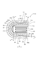
- FIG. 3 is a partially enlarged cross-sectional view of a gas sensor element in Example 1.
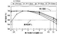
- FIG. 3 is a diagram illustrating a relationship between a position where a heat generating portion is formed and an element temperature in the first embodiment.
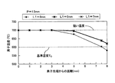
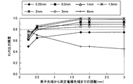
- FIG. 3 is a diagram illustrating a relationship between the length of a heat generating portion and element temperature in Example 1. The figure which shows the relationship between the formation position of a heat-emitting part and sensor output in Example 1.
- FIG. The figure which shows the relationship between the formation position of a heat-emitting part and sensor output in Example 1.
- FIG. FIG. 3 is a diagram showing the relationship between the thickness of the diffused resistance layer and the power consumption in Example 1.
- FIG. 3 is a diagram illustrating the relationship between the thickness of the diffusion resistance layer and the sensor output in the first embodiment. The figure which shows the relationship between the porosity of a diffused resistance layer, and a sensor output in Example 1.
- FIG. 9 is a partially enlarged view of a cross section of a gas sensor element in Example 2.
- the gas sensor of the present disclosure can be used for a detection mechanism of a specific gas concentration in exhaust gas of an internal combustion engine provided in an automobile or the like.
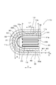
- the gas sensor 1 of this example includes a gas sensor element 10.
- the gas sensor element 10 includes a bottomed cylindrical cup-shaped solid electrolyte body 11, a reference electrode 12 formed on an inner surface 11 a of the solid electrolyte body 11, and an outer surface of the solid electrolyte body 11.
- the gas sensor element 10 is configured to output a limit current value depending on a specific gas concentration in the gas to be measured by applying a predetermined voltage between the reference electrode 12 and the measurement electrode 13.
- This is a current type gas sensor element.
- the measurement electrode 13 has a length L2 in the axial direction X of 0.5 mm to 3.0 mm, and extends from the tip of the solid electrolyte body 11 (tip of the outer surface 11b of the solid electrolyte body 11) 11c. It is within the range of 0.5 mm to 7.5 mm in the axial direction X.
- “to” that defines a numerical range means a range including a boundary numerical value.
- the “tip side” is one side in the axial direction X of the gas sensor 1 and refers to the side where the gas sensor 1 is exposed to the gas to be measured.
- the “base end side” refers to the opposite side.
- the solid electrolyte body 11 is made of ceramics mainly composed of zirconia.
- the solid electrolyte body 11 has a bottomed cylindrical cup shape.
- the opening-side end portion of the solid electrolyte body 11 (that is, the upper end portion in FIG. 1) is a base end 11d, and the opposite side of the base end 11d is a front end 11c.
- the tip 11c is curved in a hemispherical shape.
- a heater 20 is provided inside the solid electrolyte body 11.
- the heater 20 includes a rod-shaped ceramic mandrel 21 and a sheet-like heat generating member 22 wound around the peripheral surface of the mandrel 21.
- the tip corner 22 a of the heat generating member 22 is in contact with the curved inner surface 11 a (reference electrode 12) at the tip 11 c of the solid electrolyte body 11.
- the tip corner 22a is located in the range of 1.5 mm to 2.0 mm from the tip 11c in the axial direction X.
- the heat generating member 22 has a heat generating portion 23 that generates heat by energizing the heat generating member 22 on the tip 11c side.
- the length L1 of the heat generating portion 23 in the axial direction X can be set to 3.0 mm to 7.0 mm.
- the heat generating portion 23 is within the range of 0.25 mm to 9.0 mm from the tip 22a of the heater 20 in the axial direction X.
- the heat generating portion 23 is positioned near the tip 22 a of the heater 20, and at least a part (all in this example) of the heat generating portion 23 faces the measurement electrode 13. .
- the reference electrode 12 is formed on a part of the inner peripheral surface 11 a of the solid electrolyte body 11 facing the heat generating portion 23 of the heater 20.
- the reference electrode 12 is formed over the entire circumference in the circumferential direction of the inner peripheral surface 11 a of the solid electrolyte body 11.
- a measurement electrode 13 is formed over substantially the entire outer peripheral surface 11 b of the solid electrolyte body 11. As shown in FIG. 1, the reference electrode 12 and the measurement electrode 13 are respectively connected to lead wires 121 and 131 drawn to the base end 11d side.
- the length L2 of the measuring electrode 13 in the axial direction X is 0.5 mm to 3.0 mm. If the length L2 is shorter than 0.5 mm, the sensor output may be small, and sufficient detection accuracy may not be obtained. On the other hand, when the length L2 is longer than 3.0 mm, variations in temperature at the measurement electrode 13 are likely to occur, and the detection accuracy may be reduced.
- the measurement electrode 13 is within a range of 0.5 mm to 7.5 mm from the tip 11 c of the solid electrolyte body 11.
- the measurement electrode 13 is within the region facing the heat generating portion 23 on the outer surface 11b of the solid electrolyte body 11 (the region indicated by the arrow L1 in FIG. 2).
- a diffusion resistance layer 30 made of a porous body that covers at least the measurement electrode 13 is provided outside the solid electrolyte body 11.
- the diffusion resistance layer 30 covers the entire area outside the solid electrolyte body 11.
- the diffusion resistance layer 30 is formed by applying a ceramic coating to the outside of the solid electrolyte body 11.
- the thickness M1 of the diffusion resistance layer 30 on the measurement electrode 13 can be 400 ⁇ m to 700 ⁇ m, and is preferably 450 ⁇ m to 600 ⁇ m.
- the porosity of the diffusion resistance layer 30 can be 2.0% to 8.0%, and preferably 4.5% to 5.5%. In this example, the porosity of the diffusion resistance layer 30 can be measured by the Archimedes method.
- the diffusion resistance layer 30 is formed so as to straddle the outer side surface of the measurement electrode 13 and the outer side surface 11b of the solid electrolyte body 11.
- the thickness M1 of the diffusion resistance layer 30 on the measurement electrode 13 and the thickness M2 of the diffusion resistance layer 30 on the outer surface 11b of the solid electrolyte body 11 excluding the measurement electrode 13 are M2 / M1 ⁇ 1. 35 relationship is satisfied, and it is preferable to satisfy the relationship of M2 / M1 ⁇ 1.25.
- the thickness M1 of the diffusion resistance layer 30 on the measurement electrode 13 means the distance from the outer surface of the measurement electrode 13 to the outer surface 30a of the diffusion resistance layer 30. It shall be said.
- the “thickness M2 of the diffusion resistance layer 30 on the outer surface 11b of the solid electrolyte body 11 excluding the measurement electrode 13” refers to a region of the outer surface 11b of the solid electrolyte body 11 where the measurement electrode 13 is not formed.
- the distance from the position corresponding to the outer side surface of the measurement electrode 13 to the outer side surface 30a of the diffusion resistance layer 30 is referred to.
- M1 ⁇ M2 and a recess 31 is formed in a portion facing the measurement electrode 13 on the outer surface 30b of the diffusion resistance layer 30.
- a porous protective layer 40 having a higher porosity than the diffusion resistance layer 30 is formed on the outer surface 30 b of the diffusion resistance layer 30.
- the protective layer 40 is provided to trap poisonous components in the measurement gas (exhaust gas).
- the protective layer 40 is a ceramic made of alumina and carries platinum.
- the protective layer 40 is provided so as to cover the entire outer side surface 30 b of the diffusion resistance layer 30.
- the thickness N of the protective layer 40 can be set to a desired thickness.
- the porosity of the protective layer 40 can be 50% to 90%. In this example, the porosity of the protective layer 40 can be measured by the Archimedes method.
- the relationship between the contact position (tip corner 22a) between the heater 20 and the solid electrolyte body 11 and the temperature variation of the outer surface 11b of the solid electrolyte body 11 was verified. Specifically, the length L1 of the heat generating portion 23 of the heater 20 was 3 mm, and the target temperature was 700 ° C. Then, the distance P between the contact position (tip corner 22a) of the heater 20 and the tip 11c is changed at intervals of 0.5 mm in the range of 1.0 mm to 2.5 mm, and the temperature of the outer surface 11b in each case is changed. Measurements were made in the range from the tip 11c to 8.0 mm. The reference temperature T 0 was 600 ° C. at which the difference between the gas species in the adsorption / desorption reaction with respect to the electrode was small, and the variation in the temperature (element temperature) of the outer surface 11b with respect to the target temperature was evaluated.
- the element temperature is equal to or higher than the reference temperature T 0 (600 ° C.) when the distance from the tip 11c of the solid electrolyte body 11 is less than 6.9 mm. It was. On the other hand, when the distance from the tip 11c of the solid electrolyte body 11 is in the range of 6.9 mm to 8.0 mm, the element temperature is lower than the reference temperature T 0 . When P was 1.5 mm, the element temperature was equal to or higher than the reference temperature T 0 when the distance from the tip 11 c of the solid electrolyte body 11 was 7.5 mm or less.
- the element temperature is lower than the reference temperature T 0 in the range where the distance from the tip 11c of the solid electrolyte body 11 is greater than 7.5 mm and equal to or less than 8.0 mm.
- P was 2.0 mm
- the element temperature was higher than the reference temperature T 0 in the range where the distance from the tip 11c of the solid electrolyte body 11 that is the entire measurement range was 8.0 mm or less.
- P was 2.5 mm
- the element temperature was lower than the reference temperature T 0 when the distance from the tip 11 c of the solid electrolyte body 11 was less than 0.24 mm.
- the element temperature was higher than the reference temperature T 0 when the distance from the tip 11c of the solid electrolyte body 11 was in the range of 0.24 to 8.0 mm. That is, under such conditions, in the range where the distance from the tip 11c is 7.5 mm or less, if P is 1.5 mm to 2.0 mm, there is little variation in temperature.
- the relationship between the length L1 of the heat generating portion 23 of the heater 20 and the temperature variation of the outer surface 11b of the solid electrolyte body 11 was verified. Specifically, as shown in FIG. 2, the distance P between the contact position (tip corner 22a) of the heater 20 and the tip 11c is 1.5 mm, and the length L1 of the heat generating portion 23 in the axial direction X is changed. Then, the temperature of the outer surface 11b in each case was measured. Then, it was evaluated based on the reference temperature T 0.
- L1 is preferably 3.0 mm to 7.0 mm.
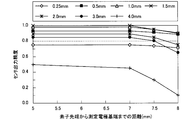
- the length L1 of the measurement electrode 13 is 0.25 mm, 0.5 mm, 1.0 mm, 1.5 mm, 2.0 mm, 3.0 mm, and 4.0 mm. I prepared something.
- the aim output value IL 0 of the gas sensor element 10 to calculate the deviation percentage (IL 1 / IL 0) for IL 0 of the IL 1 as a sensor output accuracy.
- the sensor output accuracy needs to be 0.8 or more.
- the length L2 of the measurement electrode 13 is 0.5 mm to 3.0 mm, and the formation position of the measurement electrode 13 is within the range of 0.5 mm to 7.5 mm from the tip 11c.
- the sensor output accuracy is 0.8 or more.
- the formation position of the measurement electrode 13 is in the range of 1.75 mm to 7.0 mm from the tip 11c, it is shown that the sensor output accuracy is substantially unchanged and stable.
- the temperature of the measurement electrode 13 is less than 600 ° C., the difference due to the gas type of the adsorption / desorption reaction with respect to the measurement electrode 13 increases, and the detection accuracy decreases. Therefore, to increase the detection accuracy, the temperature of the measurement electrode 13 is It is preferable that the temperature be 600 ° C or higher.
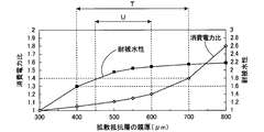
- the power consumption in the gas sensor 1 of the present example was calculated assuming that the power consumption when the M1 is 300 ⁇ m is 1. If the power consumption ratio exceeds 1.4, there is a concern about the influence on fuel consumption, and therefore the power consumption ratio needs to be 1.4 or less. Moreover, in order to suppress the increase in power consumption, the power consumption ratio needs to be 1.2 or less. As shown in FIG.
- the power consumption ratio is 1.4 or less. Further, it was shown that when the thickness M1 of the diffusion resistance layer 30 on the measurement electrode 13 is 600 ⁇ m or less, the power consumption ratio is 1.2 or less.
- the water resistance is changed to the thickness M1 of the diffusion resistance layer 30 on the measurement electrode 13 of 300 ⁇ m. It was compared with the water resistance at the time. Specifically, the element temperature of the 3 mm portion from the tip of the element is set to 700 ° C., a water droplet is dropped from the tip 11 c to the base end 11 d side at a position of 3 mm, and the amount of water dropped is increased until the gas sensor element 10 is broken. The amount of dropped water droplets at which the cracks occur was defined as water resistance.
- the water resistance when M1 was 300 ⁇ m was set to 1, and the water resistance when M1 was changed between 300 ⁇ m and 800 ⁇ m was calculated.
- the water resistance needs to be 1.6 or more.
- the water resistance needs to be 1.8 or more.
- the thickness M1 of the diffusion resistance layer 30 is 400 ⁇ m or more, the water resistance is 1.6 or more.
- the thickness M1 of the diffusion resistance layer 30 is 450 ⁇ m or more, the water resistance is 1.8 or more.
- the thickness M1 of the diffusion resistance layer 30 on the measurement electrode 13 needs to be in the range indicated by the arrow T in FIG. 7, that is, 400 ⁇ m to 700 ⁇ m. It was. Further, it was shown that the thickness M1 of the diffusion resistance layer 30 on the measurement electrode 13 is preferably in the range indicated by the arrow U in FIG. 7, that is, 450 ⁇ m to 600 ⁇ m.
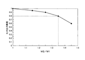
- the sensor output accuracy (IL / IL m ) needs to be 0.9 or more. As shown in FIG. 8, when M2 / M1 ⁇ 1.35, the sensor output accuracy (IL / IL m ) is 0.8 or more. Further, when M2 / M1 ⁇ 1.25, the sensor output accuracy (IL / IL m ) is 0.9 or more.
- the thickness M1 of the diffusion resistance layer 30 on the measurement electrode 13 and the thickness M2 on the solid electrolyte body 11 excluding the measurement electrode 13 need to satisfy M2 / M1 ⁇ 1.35, and M2 It was confirmed that /M1 ⁇ 1.25 is preferable.
- the sensor output value IL is detected by changing the porosity of the diffusion resistance layer 30 in a range of 1.0% to 14.0%, and the conventional O 2 sensor having a protective layer with a porosity of 5.0% is used.
- the sensor output accuracy (IL / IL 0 ) was calculated based on the sensor output IL 0 . In order to obtain sufficient A / F detection accuracy, the sensor output accuracy needs to be 0.8 or more. As shown in FIG. 9, when the porosity of the diffusion resistance layer 30 is 2.0% to 8.0%, the sensor output accuracy is 0.8 or more. Therefore, it was confirmed that the porosity of the diffusion resistance layer 30 is required to be 2.0% to 8.0%.
- the effect in the gas sensor 1 of this example is explained in full detail.
- the measurement electrode 13 has a length L1 in the axial direction X of 0.5 mm to 3.0 mm and is within a range of 0.5 mm to 7.5 mm from the tip 11c of the solid electrolyte body 11.
- the measurement electrode 13 is formed with a sufficiently short length L1 in the axial direction X, and is provided within a predetermined range from the tip 11c of the solid electrolyte body 11.
- variation in the temperature in the measurement electrode 13 can be suppressed, and the dispersion
- variation in gas adsorption reactivity is reduced in a small amount of gas atmosphere at stoichiometry, and variation in stoichiometric detection performance is suppressed.
- by mounting (rear mounting) on the downstream side of the catalyst of a vehicle having a very small gas atmosphere the A / F can always be detected with high accuracy and can be applied to stoichiometric control.
- the diffusion resistance layer 30 is porous and is formed on the measurement electrode 13, the amount of gas reaction at the measurement electrode 13 can be controlled. Thereby, the detection accuracy of A / F can be improved.
- the thickness M1 of the diffusion resistance layer 30 on the measurement electrode 13 is set to 400 ⁇ m to 700 ⁇ m. As a result, it is possible to achieve both A / F detection accuracy improvement, power consumption reduction, and shortening of the activation time of the solid electrolyte body 11. Furthermore, by setting the thickness M1 of the diffusion resistance layer 30 on the measurement electrode 13 to 450 ⁇ m to 600 ⁇ m, it is possible to more effectively improve the A / F detection accuracy, reduce the power consumption, and shorten the activation time.
- the porosity of the diffusion resistance layer 30 is set to 2.0% to 8.0%.
- the influence namely, temperature characteristic
- the A / F detection accuracy can be improved.
- the porosity of the diffusion resistance layer 30 is set to 4.5% to 5.5%, the temperature characteristics can be further reduced, and the A / F detection accuracy can be further improved.
- the diffusion resistance layer 30 is formed so as to straddle the outer surface of the measurement electrode 13 and the outer surface 11b of the solid electrolyte body 11.
- the thickness M1 of the diffusion resistance layer 30 on the measurement electrode 13 and the thickness M2 on the solid electrolyte body 11 satisfy the relationship of M2 / M1 ⁇ 1.35.
- M2 / M1 ⁇ 1.25 it is possible to further improve the A / F detection accuracy and reduce the thermal stress.
- a protective layer 40 made of a porous material having a higher porosity than the diffusion resistance layer 30 is formed on the outer surface 30 a of the diffusion resistance layer 30.
- the protective layer 40 contains platinum.
- platinum can accelerate
- FIG. it is possible to prevent hydrogen gas from reaching the measurement electrode 13 ahead of other components in the exhaust gas and shifting the sensor output to the rich side. As a result, the A / F detection accuracy can be improved.
- the measurement electrode 13 is within the region facing the heat generating portion 23 on the outer surface 11b of the solid electrolyte body 11 (the region indicated by the arrow L1 in FIG. 2).
- the heat of the heater 20 is transferred from the tip corner 22a to the measurement electrode 13 via the solid electrolyte body 11 and easily reaches the measurement electrode 13 by radiation. It becomes easy to reach the entire 13 uniformly. Thereby, the temperature variation of the measurement electrode 13 can be made smaller. As a result, the A / F detection accuracy can be improved.
- the tip corner 22a that contacts the inner surface 11a of the solid electrolyte body 11 in the heater 20 is located in the range of 1.5 mm to 2.0 mm from the tip 11c of the solid electrolyte body 11 in the axial direction X. .
- the length L1 of the heat generating portion 23 of the heater 20 is 3.0 mm to 7.0 mm, and the heat generating portion 23 is within 0.25 mm to 9.0 mm from the tip 22a of the heater 20 in the axial direction X. Is in the range.
- the heat generating part 23 is arranged on the side close to the tip 22a that is the contact position between the solid electrolyte body 11 and the heater 20, and at least a part (all in this example) of the heat generating part 23 is placed on the measurement electrode 13. It will be opposite. Therefore, the heat generated from the heat generating portion 23 can be efficiently propagated to the measurement electrode 13 via the tip 22a of the heater 20, and thus the temperature variation of the measurement electrode 13 can be further reduced. As a result, it is possible to further improve the A / F detection accuracy.
- the gas sensor element 10 that is excellent in rapid thermal performance and can detect A / F with high accuracy.
- symbol is attached
Landscapes
- Chemical & Material Sciences (AREA)
- Life Sciences & Earth Sciences (AREA)
- Health & Medical Sciences (AREA)
- Physics & Mathematics (AREA)
- Chemical Kinetics & Catalysis (AREA)
- Electrochemistry (AREA)
- Molecular Biology (AREA)
- Analytical Chemistry (AREA)
- Biochemistry (AREA)
- General Health & Medical Sciences (AREA)
- General Physics & Mathematics (AREA)
- Immunology (AREA)
- Pathology (AREA)
- Measuring Oxygen Concentration In Cells (AREA)
Abstract
L'invention porte sur un capteur de gaz, lequel capteur a des propriétés de chauffage rapide exceptionnelles, et avec lequel il est possible de détecter le rapport air/carburant avec une précision élevée, et de détecter le rapport stœchiométrique avec une précision élevée. Ce capteur de gaz (1) a un élément capteur de gaz à limitation de courant (10). L'élément capteur de gaz (10) a un électrolyte solide en forme de coupelle (11), une électrode de référence (12) formée sur la surface intérieure (11a) de l'électrolyte solide (11), une électrode de mesure (13) formée sur la surface extérieure (11b) de l'électrolyte solide (11), et un élément chauffant (20). L'élément chauffant (20) est disposé à l'intérieur de l'électrolyte solide (11) de telle sorte que l'extrémité distale vient en contact avec la surface intérieure (11a) de l'électrolyte solide (11). Le capteur de gaz (1) applique une tension prescrite entre l'électrode de référence (12) et l'électrode de mesure (13), et délivre ainsi en sortie une valeur de courant de limitation qui dépend de la concentration d'oxygène dans des gaz d'échappement. L'électrode de mesure (13) a une longueur de 0,5 à 3,0 mm dans la direction axiale X, et est disposée à l'intérieur d'une plage de 0,5 à 7,5 mm dans la direction axiale X à partir de l'extrémité distale (11c) de l'électrolyte solide (11).
Priority Applications (3)
| Application Number | Priority Date | Filing Date | Title |
|---|---|---|---|
| DE112015003077.8T DE112015003077B4 (de) | 2014-06-30 | 2015-06-30 | Gassensor |
| US15/322,781 US10473614B2 (en) | 2014-06-30 | 2015-06-30 | Gas sensor |
| CN201580035795.2A CN106662548B (zh) | 2014-06-30 | 2015-06-30 | 气体传感器 |
Applications Claiming Priority (4)
| Application Number | Priority Date | Filing Date | Title |
|---|---|---|---|
| JP2014-133486 | 2014-06-30 | ||
| JP2014133486 | 2014-06-30 | ||
| JP2015-025182 | 2015-02-12 | ||
| JP2015025182A JP6350326B2 (ja) | 2014-06-30 | 2015-02-12 | ガスセンサ |
Publications (1)
| Publication Number | Publication Date |
|---|---|
| WO2016002793A1 true WO2016002793A1 (fr) | 2016-01-07 |
Family
ID=55019325
Family Applications (1)
| Application Number | Title | Priority Date | Filing Date |
|---|---|---|---|
| PCT/JP2015/068866 Ceased WO2016002793A1 (fr) | 2014-06-30 | 2015-06-30 | Capteur de gaz |
Country Status (5)
| Country | Link |
|---|---|
| US (1) | US10473614B2 (fr) |
| JP (1) | JP6350326B2 (fr) |
| CN (1) | CN106662548B (fr) |
| DE (1) | DE112015003077B4 (fr) |
| WO (1) | WO2016002793A1 (fr) |
Cited By (1)
| Publication number | Priority date | Publication date | Assignee | Title |
|---|---|---|---|---|
| CN108693215A (zh) * | 2017-03-31 | 2018-10-23 | 日本碍子株式会社 | 气体传感器 |
Families Citing this family (4)
| Publication number | Priority date | Publication date | Assignee | Title |
|---|---|---|---|---|
| JP6350326B2 (ja) | 2014-06-30 | 2018-07-04 | 株式会社デンソー | ガスセンサ |
| JP6885885B2 (ja) * | 2018-02-14 | 2021-06-16 | 日本特殊陶業株式会社 | ガスセンサ素子およびガスセンサ |
| JP6998801B2 (ja) * | 2018-03-12 | 2022-02-04 | 日本碍子株式会社 | ガスセンサ |
| JP7382857B2 (ja) * | 2020-03-09 | 2023-11-17 | 日本碍子株式会社 | ガスセンサ |
Citations (4)
| Publication number | Priority date | Publication date | Assignee | Title |
|---|---|---|---|---|
| JPS60179862U (ja) * | 1984-05-07 | 1985-11-29 | 株式会社デンソー | 酸素濃度検出器 |
| JPH08271474A (ja) * | 1995-02-01 | 1996-10-18 | Nippondenso Co Ltd | 酸素濃度検出器 |
| JP2000137016A (ja) * | 1998-11-02 | 2000-05-16 | Denso Corp | ガスセンサ素子 |
| JP2009180669A (ja) * | 2008-01-31 | 2009-08-13 | Toyota Motor Corp | 空燃比センサ |
Family Cites Families (10)
| Publication number | Priority date | Publication date | Assignee | Title |
|---|---|---|---|---|
| JP3811991B2 (ja) | 1996-05-21 | 2006-08-23 | 株式会社デンソー | 酸素センサ素子の製造方法及び酸素センサ素子 |
| DE69814318T2 (de) * | 1997-11-20 | 2004-04-08 | Denso Corp., Kariya | Festelektrolyt mit innerer Referenzkammer und Elektroden auf Innen- und Aussenflächen |
| JP3531859B2 (ja) | 1998-09-28 | 2004-05-31 | 株式会社デンソー | ガスセンサ |
| JP2005326396A (ja) | 2004-04-15 | 2005-11-24 | Denso Corp | ガスセンサ |
| JP4587473B2 (ja) * | 2004-07-22 | 2010-11-24 | 日本特殊陶業株式会社 | ガスセンサ |
| JP5182321B2 (ja) * | 2010-05-13 | 2013-04-17 | 株式会社デンソー | ガスセンサ素子、及び、これを内蔵したガスセンサ |
| JP5488289B2 (ja) * | 2010-07-21 | 2014-05-14 | 株式会社デンソー | 酸素センサ素子 |
| JP2013238556A (ja) * | 2012-05-17 | 2013-11-28 | Denso Corp | ガスセンサ |
| JP5846131B2 (ja) | 2013-01-10 | 2016-01-20 | 横浜ゴム株式会社 | 空気入りタイヤ |
| JP6350326B2 (ja) | 2014-06-30 | 2018-07-04 | 株式会社デンソー | ガスセンサ |
-
2015
- 2015-02-12 JP JP2015025182A patent/JP6350326B2/ja active Active
- 2015-06-30 US US15/322,781 patent/US10473614B2/en active Active
- 2015-06-30 CN CN201580035795.2A patent/CN106662548B/zh active Active
- 2015-06-30 WO PCT/JP2015/068866 patent/WO2016002793A1/fr not_active Ceased
- 2015-06-30 DE DE112015003077.8T patent/DE112015003077B4/de active Active
Patent Citations (4)
| Publication number | Priority date | Publication date | Assignee | Title |
|---|---|---|---|---|
| JPS60179862U (ja) * | 1984-05-07 | 1985-11-29 | 株式会社デンソー | 酸素濃度検出器 |
| JPH08271474A (ja) * | 1995-02-01 | 1996-10-18 | Nippondenso Co Ltd | 酸素濃度検出器 |
| JP2000137016A (ja) * | 1998-11-02 | 2000-05-16 | Denso Corp | ガスセンサ素子 |
| JP2009180669A (ja) * | 2008-01-31 | 2009-08-13 | Toyota Motor Corp | 空燃比センサ |
Cited By (3)
| Publication number | Priority date | Publication date | Assignee | Title |
|---|---|---|---|---|
| CN108693215A (zh) * | 2017-03-31 | 2018-10-23 | 日本碍子株式会社 | 气体传感器 |
| CN108693215B (zh) * | 2017-03-31 | 2022-09-02 | 日本碍子株式会社 | 气体传感器 |
| US11885764B2 (en) | 2017-03-31 | 2024-01-30 | Ngk Insulators, Ltd. | Gas sensor |
Also Published As
| Publication number | Publication date |
|---|---|
| JP6350326B2 (ja) | 2018-07-04 |
| DE112015003077B4 (de) | 2022-08-04 |
| US20170108463A1 (en) | 2017-04-20 |
| CN106662548A (zh) | 2017-05-10 |
| DE112015003077T5 (de) | 2017-03-16 |
| JP2016027312A (ja) | 2016-02-18 |
| US10473614B2 (en) | 2019-11-12 |
| CN106662548B (zh) | 2019-04-23 |
Similar Documents
| Publication | Publication Date | Title |
|---|---|---|
| JP6350326B2 (ja) | ガスセンサ | |
| JP5182321B2 (ja) | ガスセンサ素子、及び、これを内蔵したガスセンサ | |
| JP5134399B2 (ja) | ガスセンサ及びガスセンサ制御装置 | |
| JP6857051B2 (ja) | ガスセンサ素子およびガスセンサ | |
| JP7103176B2 (ja) | ガスセンサの故障検出装置、ガスセンサの故障検出方法 | |
| WO2022123866A1 (fr) | Capteur de gaz | |
| CN105765377B (zh) | 氧传感器元件 | |
| WO2011148598A1 (fr) | Capteur de gaz | |
| JP2002031618A (ja) | ガスセンサ | |
| JP6476607B2 (ja) | ガスセンサ素子 | |
| CN110159441B (zh) | 内燃机的控制装置 | |
| JP7194555B2 (ja) | ガスセンサ | |
| US11604160B2 (en) | Gas sensor | |
| JP6880179B2 (ja) | ガスセンサ素子およびガスセンサ | |
| JP6204252B2 (ja) | アンモニアガスセンサ | |
| JP6885885B2 (ja) | ガスセンサ素子およびガスセンサ | |
| CN103314205A (zh) | 内燃机的控制装置 | |
| JP6350290B2 (ja) | 酸素センサ | |
| JPH11242012A (ja) | 酸素センサ | |
| JP4901969B2 (ja) | 酸素検出素子 | |
| JP2005195368A (ja) | 酸素濃度検出制御装置 | |
| JP4593979B2 (ja) | ガスセンサ及びガス検出方法 | |
| JP2016121880A (ja) | センサ制御装置 | |
| JP6274554B2 (ja) | ガスセンサ素子、及びガスセンサ | |
| JP2022160157A (ja) | ガスセンサ制御装置、ガスセンサ制御方法 |
Legal Events
| Date | Code | Title | Description |
|---|---|---|---|
| 121 | Ep: the epo has been informed by wipo that ep was designated in this application |
Ref document number: 15814769 Country of ref document: EP Kind code of ref document: A1 |
|
| WWE | Wipo information: entry into national phase |
Ref document number: 15322781 Country of ref document: US |
|
| WWE | Wipo information: entry into national phase |
Ref document number: 112015003077 Country of ref document: DE |
|
| 122 | Ep: pct application non-entry in european phase |
Ref document number: 15814769 Country of ref document: EP Kind code of ref document: A1 |